1. Introduction
Using adequately controlled reflectors (mirrors) that capture and focus sunlight onto a receiver, conventional point focusing technologies are an important part of the vaster group of concentrated solar power (CSP) systems. These systems can provide high fluxes of sunlight into the receiver, and consequently reach high temperatures. By driving a heat engine (usually a steam turbine) connected to an electrical power generator, the solar heat can be used to generate electricity [
1]. Alternatively, the solar heat can be used to power a thermochemical reaction [
2,
3].
Compared to other sources of energy, the direct application of concentrated solar radiation on a target (material or process reaction chamber), besides being free and clean, also brings other major advantages, such as the possibility to achieve very rapid heating and very high temperatures. However, despite its advantages, there is a difficulty inherent in the current use of point-focusing solar concentration technology for certain applications because the flux of solar radiation that reaches the target is theoretically non-homogeneous. A circle illuminated with a higher concentration in the middle of the target/receiver is theoretically obtained when the paraboloid reflection model [
4] is applied to the traditional solar concentrators, utilizing a point-focusing solar concentrating panel assembly. Depending on the type of application of the solar heating process, non-uniform temperature distributions may cause adverse effects. In fact, a non-homogeneous solar flux irradiation has several disadvantages which may prove to be critical in some relevant areas of work, such as materials’ processing. For example, large thermal gradients caused by a low homogeneity flux distribution can lead to defects or cracking during the consolidation of ceramic pieces by solar-sintering [
5] or the heterogeneous composition of solar-synthesised graphite/tungsten composites [
6].
As early as 1961, schemes of obtaining uniform irradiation over a large area in a solar furnace have been proposed [
7]. Light pipes used to redistribute the flux generated by the parabolic concentrator of a solar furnace are commonly known as radiation flux “homogenisers”. Most of them consist of multi-reflective devices (with mirrored sides) designed to reshape the solar radiation flux coming from a concentrator so that, after passing through the homogeniser, the flux becomes as much evenly distributed as possible. For construction reasons, homogenisers used in high-flux solar furnaces should be simple, with flat reflective surfaces or a cylinder mirrored inside and an optical behaviour similar to a symmetric polygon with infinite faces [
8]. However, multi-reflection radiation homogenisers are prone to be easily damaged at high temperatures and their degree of success achieved is just satisfactory [
8]. It seems fair to say that, although multi-reflection homogenisers are a reasonable workaround to solve an important difficulty in high-flux solar furnaces, they are not a robust, solid solution for the problem, and it would be highly desirable for the industry to find a better solution.
The photovoltaic (PV) systems that use concentrated sunlight are called concentrating photovoltaics (CPV). Moreover, for CPV, there is also a need for homogeneous flux distribution. Since an array of solar cells is limited in output current by the lowest cell current, photovoltaic modules require a uniform flux distribution for operation at maximum efficiency [
9]. Several homogeniser configurations are well documented in the CPV field. For instance, prism-based, working on the principle of total internal reflection [
10]; mirror-based, working on multiple reflections using several mirrored facets [
9,
11,
12,
13]; or those that are lens-based, such as the Köhler homogeniser [
14], or domed homogenisers, as in [
15,
16].
In the context of an analysis conducted over a former Portuguese Patent Pending Request [
17], our research group was able to demonstrate in previous works [
4,
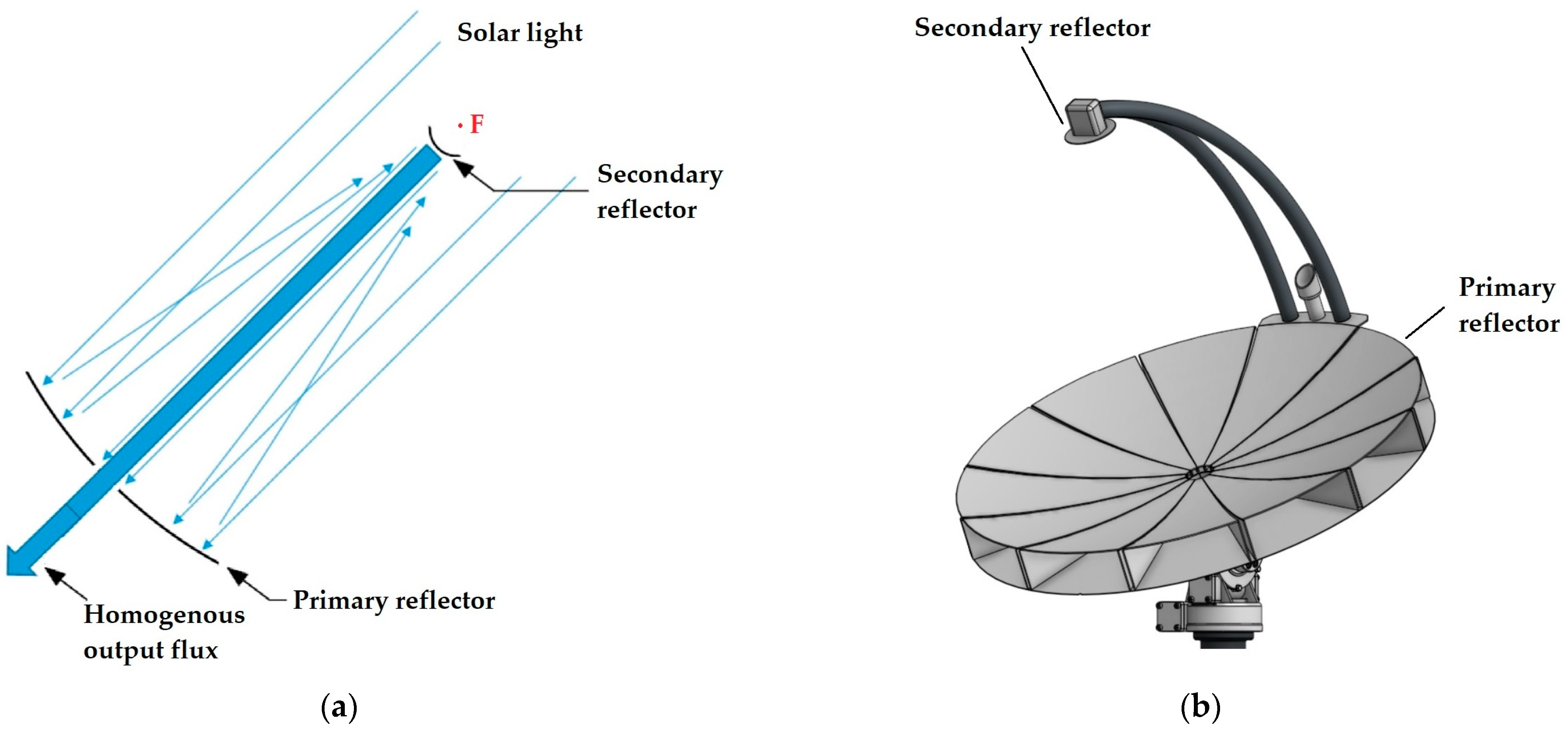
18] that theoretically quasi-homogeneous solar flux distribution can be obtained by means of a double reflection using two paraboloid-reflecting surfaces when a single focal point is shared between those two paraboloids. The second paraboloid can be convex and positioned before the focal point (as in
Figure 1) or concave and positioned after the focal point [
4,
18]. Such a system draws parallels from the Cassegrain reflector that is widely used in optical and radio astronomy [
19], with the difference being that the parabolic secondary reflector (as opposed to a hyperbolic one) does not focus light to a point, but produces a uniform light beam.
The objective of the present work is the experimental demonstration of the technical feasibility of obtaining a highly homogeneous concentrated solar flux distribution by means of a “double paraboloid reflection” (i.e., a double reflection using two paraboloid surfaces). This is a complete novelty, because, even when arrangements “with double reflection” were mentioned in some previous publications, in any one of them it has been mentioned that, for obtaining a quasi-homogeneous flux, two paraboloids must be involved, and both must have the same focal point. For that, we used a solar furnace installation: the solar furnace SF60 located in PSA—Plataforma Solar de Almería, Spain, which is equipped with a large paraboloid concentrator, and we have fabricated the secondary reflector matching the specific optical configuration. In this study, the secondary paraboloid reflectors will be convex, i.e., are placed before the focal point, as shown in
Figure 1. The external diameter of those secondary reflectors will be kept constant (191 mm, which will be further explained later).
2. Materials and Methods
2.1. Testing Facility
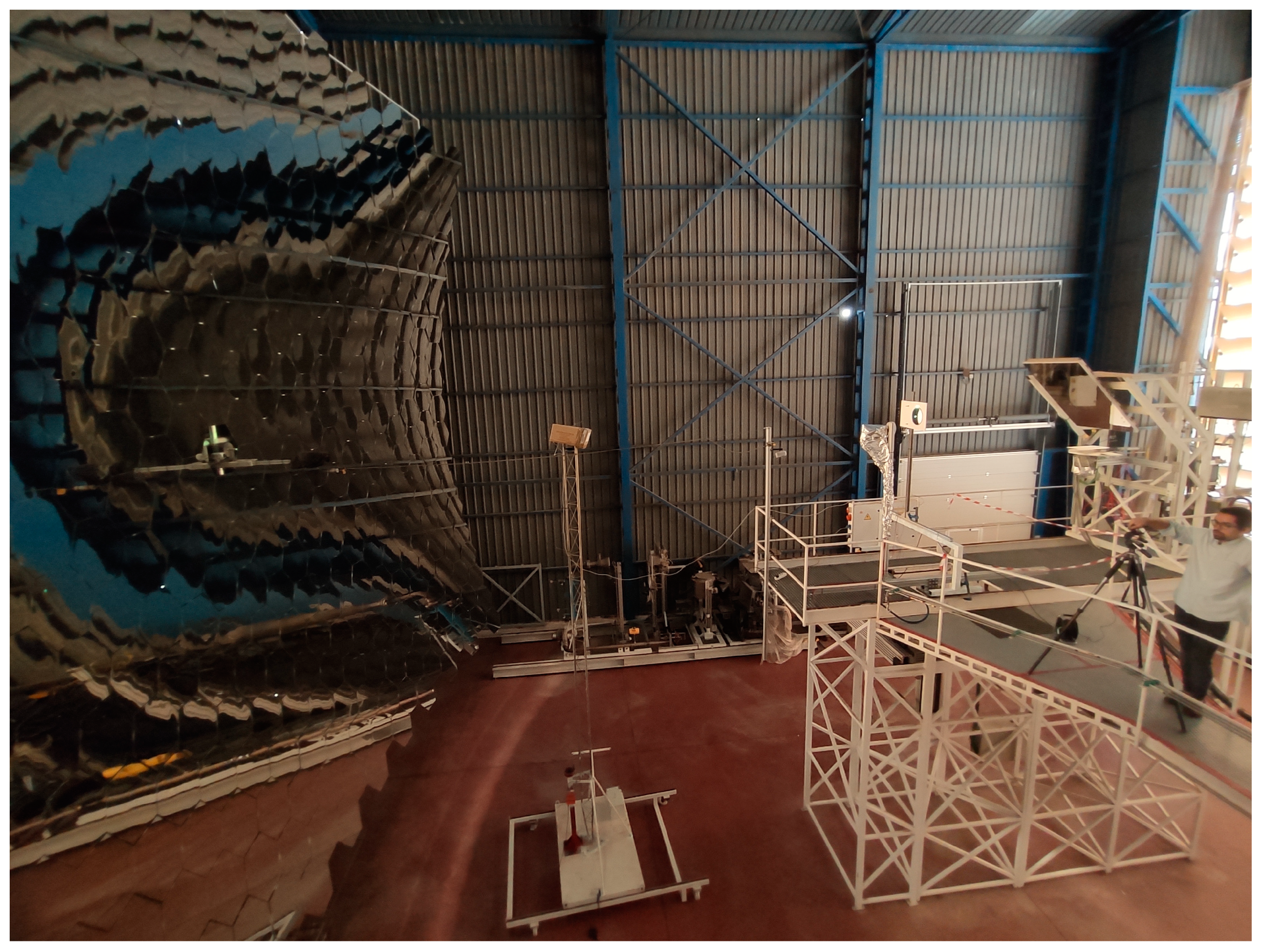
The recently renewed SF60 solar concentrator (depicted in
Figure 2) is composed of 463 hexagonal facets, approximating a paraboloid surface. This new paraboloid concentrator, named FAHEX 100 (a prototype fabricated by PSA—Plataforma Solar de Almería, Tabernas, Spain), shows the following optical characteristics [
21]:
Focal length f: 7800 mm;
Focal spot diameter (for 90% of the power): 22 cm;
Horizontal rim angle: 40.3°;
Vertical rim angle: 35.3°.
The SF60 facility is further equipped with a supporting platform where measurements take place, which is equipped with an XYZ stage (working table) that is capable of positioning equipment inside a large work volume.
2.2. Computational Details
Since our 2017 solar testing campaign in PSA—Plataforma Solar de Almería (still with the former configuration of the SF60 solar furnace), we have been developing our own ray-tracing modelling software, which allowed us to prove the possibility of attaining quasi-homogeneous flux distribution by using the herein mentioned “double paraboloid reflection” [
4].
We concluded that the parallel and homogeneous output beam is not affected by the position and curvature of the two paraboloids (as long as they have the same focal point); only the beam radius and intensity change [
18]. Therefore, when decreasing the size of the second paraboloid, a more intense and narrower beam is obtained. This is an interesting optical design, but it requires a high precision in the geometry of the two paraboloids.
Moreover, assuming that the solar radiation flux provided by the heliostat can be represented by parallel rays, we concluded that the optical arrangement for the “double paraboloid reflection” produces exactly the same results using either a secondary convex paraboloid, positioned before the focal point (the layout shown in
Figure 1), or a concave paraboloid, positioned after the focal point.
However, we also concluded that this is no longer the case if we assume that solar rays reach the Earth with an inclination angle between 0° and 0.267° (the maximum inclination theoretically predicted for the Sun’s rays, taking into account the Sun’s radius and the average Sun–Earth distance; see [
18] for details). In this case, the slightly more compact convex layout (
Figure 1) produces slightly smaller losses (the rays diverge less).
Based on the above-mentioned characteristics of the SF60 concentrator, we have used our experience in ray-tracing modelling to decide on the dimensions of the “sample(s)”; i.e., the small secondary reflector(s) that have been tested in this study.
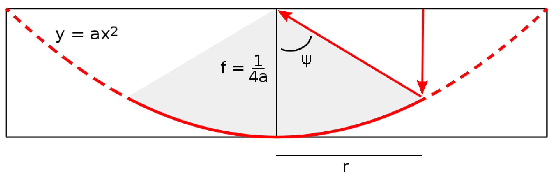
The optical behaviour of an ideal reflecting paraboloid (
), receiving light rays parallel to its axis (see
Figure 3), can be described by its unique focal length
(derived in [
4]) where
a is the curvature, and by its rim angle Ψ (the maximum angle that reflected rays make with the paraboloid axis). The paraboloid projected radius can then be calculated using the equation (derived in [
4]):
In this work, we used the data reported by PSA—Plataforma Solar de Almería [
21] for the SF60 solar furnace recently renewed:
z = 7800 mm and Ψ = 35.3° (the smallest of the two rim angles reported in
Section 2.1); thus, the projected radius for the large paraboloid becomes 4963 mm.
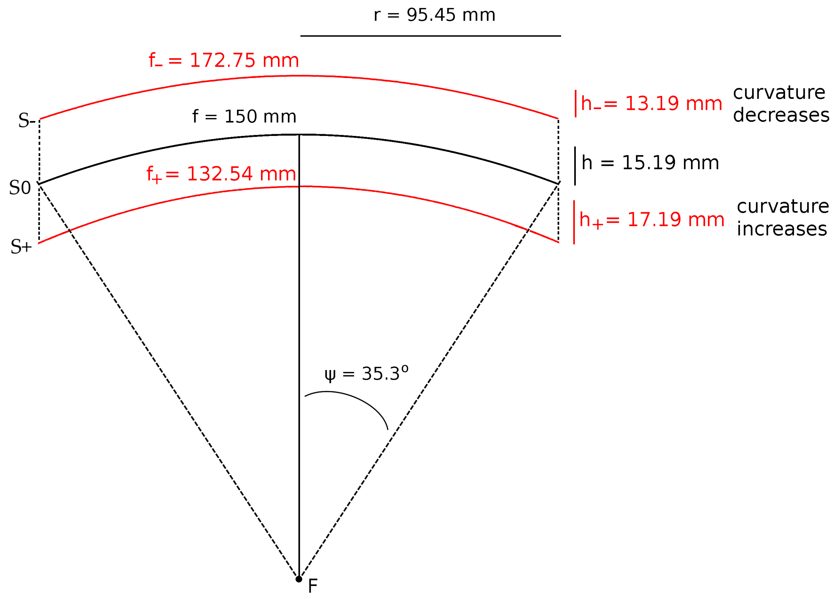
To study the optical behaviour of the double paraboloid geometry (see
Figure 1), we built a small paraboloid (labelled “S0”), using the same rim angle and a focal length of 150 mm (
a = 0.001667 mm
−1). For this paraboloid, the projected radius becomes 95.45 mm and the external height (the
h height of the outer circumference; see
Figure 4) is 15.19 mm.
In practise, the geometry of a manufactured reflecting surface is never going to be mathematically perfect in a real-life device. A practical paraboloid reflector exhibits dimensional and geometric deviations due to manufacturing limitations and its structural stiffness; thus, it is important to assess how the behaviour of the optical arrangement is affected by those inaccuracies. To study how the small paraboloid geometry affects the results, we built two more paraboloids, with an external height 2 mm smaller (13.19 mm) (labelled “S−”) and 2 mm larger (17.19 mm) (labelled “S+”). Keeping the projected radius (95.45 mm) constant, the curvature and focal length of paraboloids S− and S+ can be calculated:
The S− paraboloid thus has a smaller curvature (a = 0.001447 mm−1) and larger focal length (f = 172.75 mm), while the S+ paraboloid has a larger curvature (a = 0.001886 mm−1) and smaller focal length (f = 132.54 mm).
As the projected radius is the same (95.45 mm) for all three paraboloids, Equation (1) can be used again, with the new curvature, to obtain the rim angle Ψ (by trial and error) that gives the required projected radius (95.45 mm) that is smaller for the S− paraboloid (Ψ = 30.9°) and larger for S+ paraboloid (Ψ = 39.6°). All of the geometrical parameters for the design of these three paraboloids are presented in
Table 1.
2.3. Dedicated Construction of Secondary Reflector
While conventional glass-based mirrors excel at having high reflectance, particularly if produced for a minimum thickness, complex processing techniques drive up the final cost of the solar installation and the time to deployment. In contrast to this, metal-based mirrors—produced by conventional manufacturing techniques such as machining—provide the advantage of being easily manufactured to match the required specifications of this application, with rapid turnover.
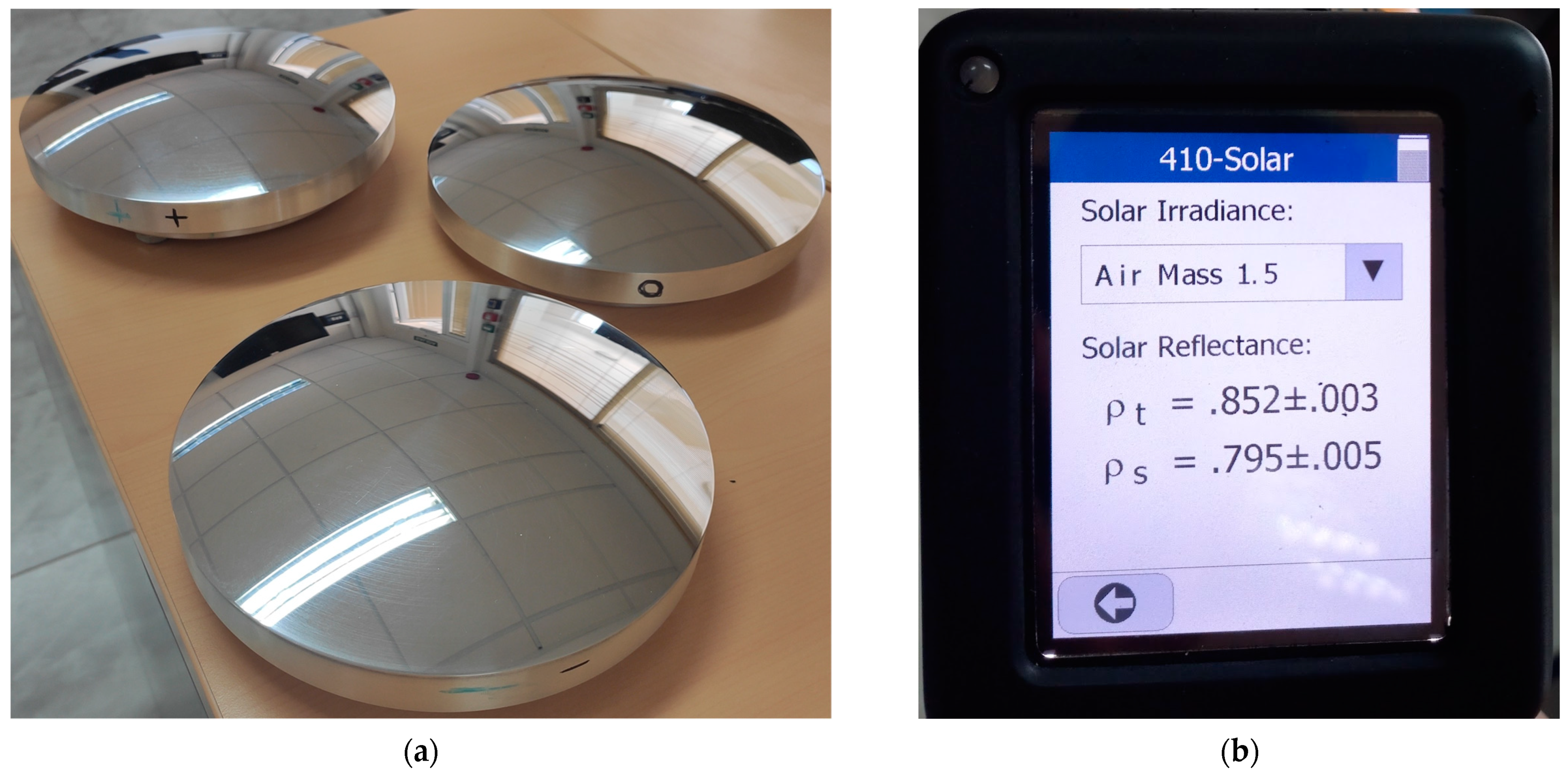
Therefore, in this work, each reflector was machined from a disc of 7075-T6 aluminium alloy, 210 mm in diameter and 51 mm height, with each face being milled on both sides to assure parallelism between the mounting and reflecting surfaces. This prepared blank was further processed in a turning centre (DMG Mori CTX 310 Ecoline 2-axis, Leonberg, Germany), which brought it to its final paraboloid shape, with careful CAM programming to ensure that a close tolerance form is achieved. To reach a mirror-like finish, successive sanding (600, 1000, 1500, 2000 and 4000 grit silicon carbide paper, Klingspor AG, Haiger, Germany) and polishing (6-, 3- and 1-micron diamond polishing compound, water soluble, Norton Abrasives, Worcester, MA, USA) steps were performed.
Figure 5 depicts the three secondary reflectors after the final polishing. Reflectance measurements of the S0 reflector obtained with a SOC410-Solar portable reflectometer from Surface Optics Corp. (San Diego, CA, USA) are presented in
Table 2.
2.4. Testing Methodology for Heat Flux Distribution Measurement
Heat flux was measured using thermo-gauges of the Gardon type (TG1000, from Vattel Corporation, Christiansburg, VA, USA). For taking measurements, one circular-foil heat flux transducer was positioned at various points on the measurement plane, with readings being taken at each point on a square-grid with a 20 mm spacing. The distance from the Gardon thermo-gauge to the reflecting surface depends on the type of measurement being performed and is detailed on the subsequent sections of this article. The Gardon gauges had a flux range of 378.7 kW/m
2 and 3508.5 kW/m
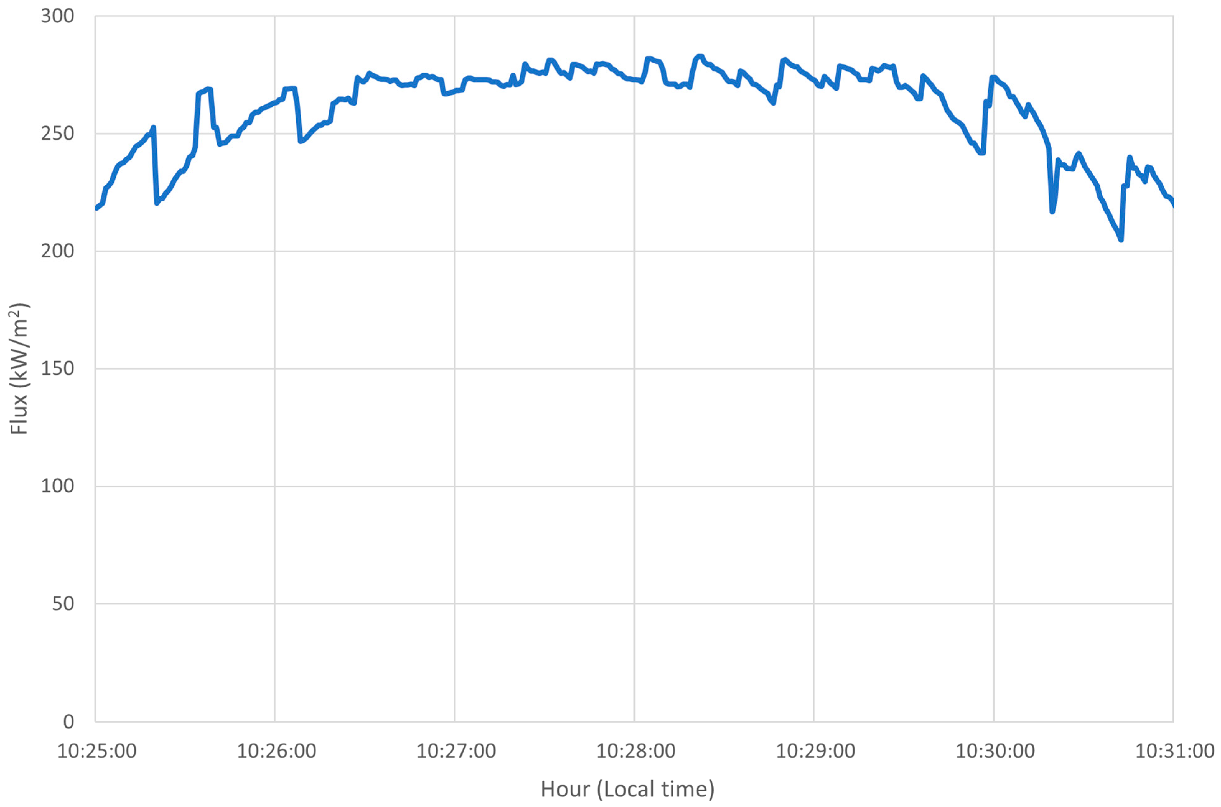
2 at a full scale (10 mV), depending on the trial type, the shutter opening, and the secondary reflector heat load. Given the nature of these sensors and the large inertia of the heliostat which tracks the Sun, a “saw-tooth” output signal of the Gardon gauge is generally obtained (see example in
Figure 6). Therefore, an average of the sensor reading was taken by measuring the heat flux at each point during at least a 10 s period. After the reading, it is necessary to manually command the XYZ working table to position the Gardon gauge to a new measurement site.
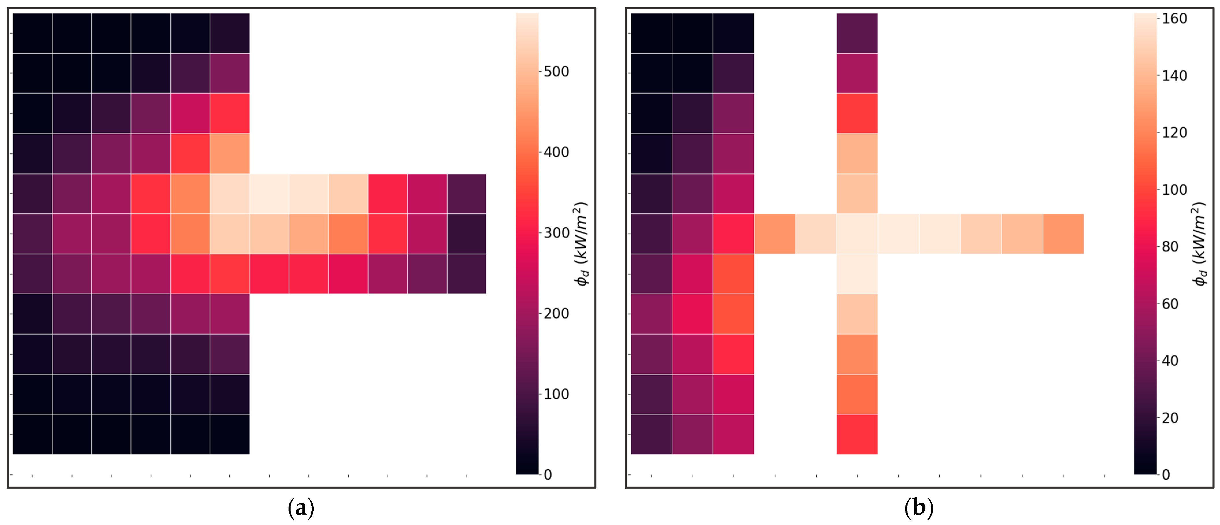
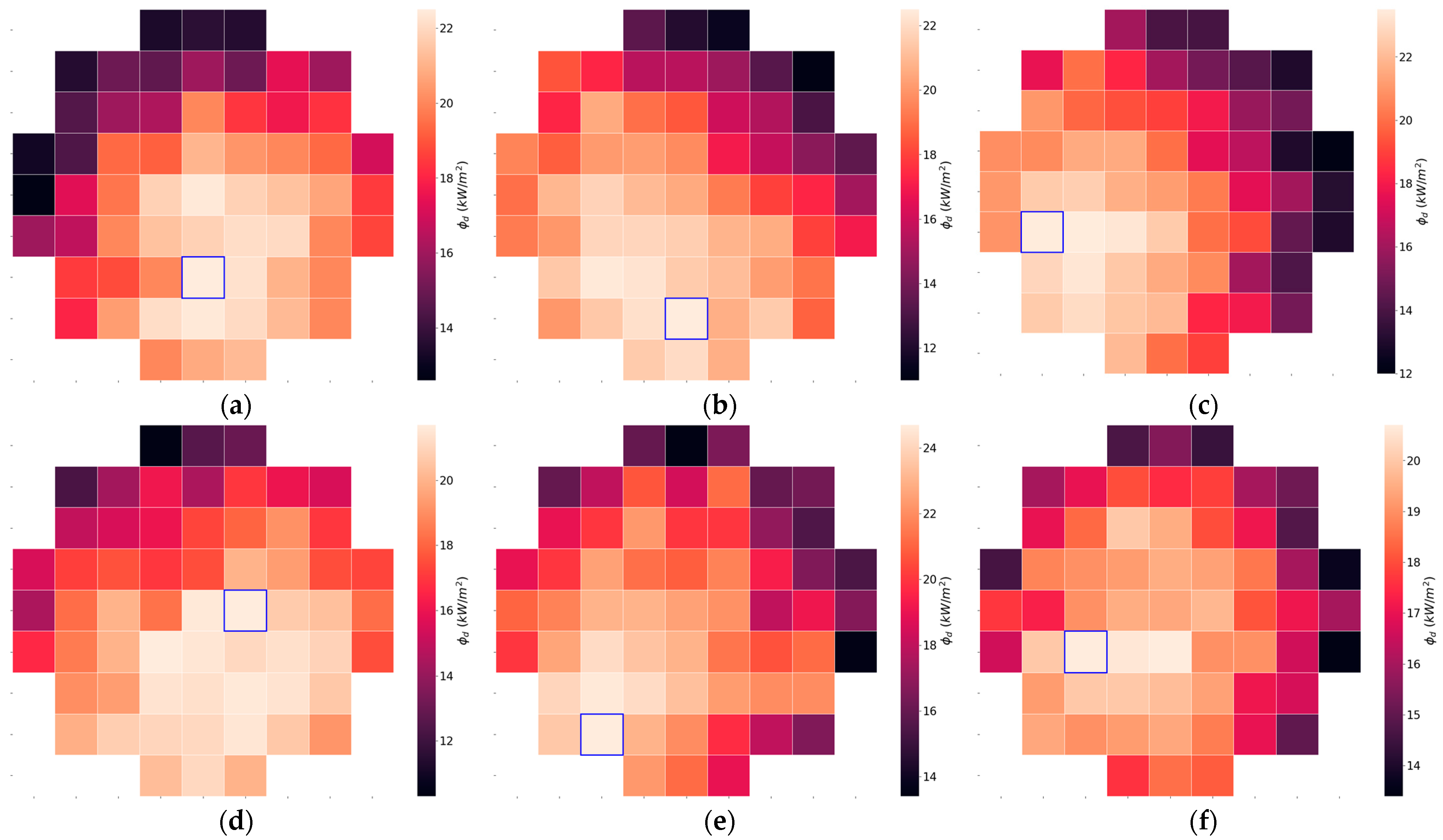
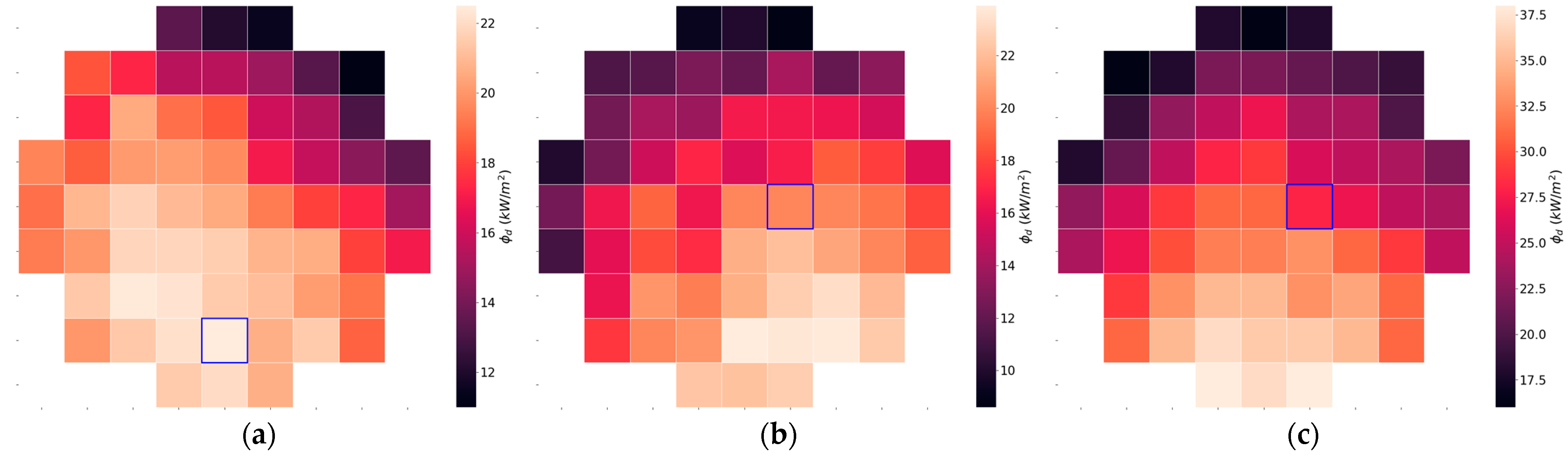
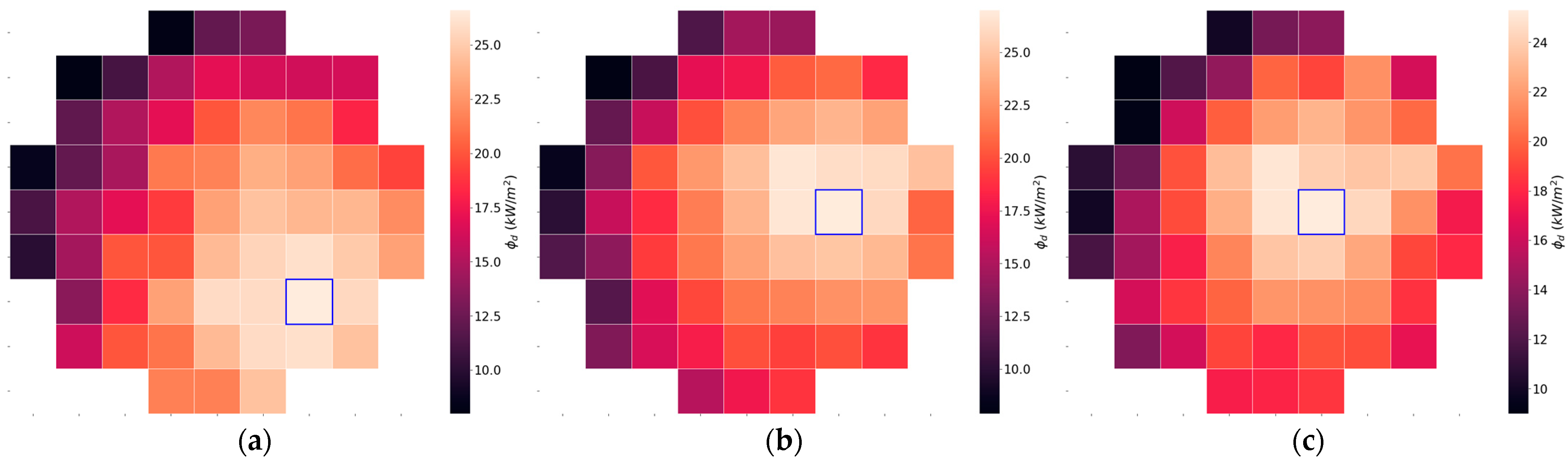
With the goal of observing the effectiveness of the double paraboloid arrangement in producing a homogeneous output flux distribution, the testing methodology was divided into steps, as follows: (i) First, as a baseline, measurements were made to understand the flux distribution of the primary reflector at its theoretical focal plane (z = 7800 mm), and at the theoretical position of the secondary reflector (z = 7650 mm); (ii) next, we measured the variation of the output flux distribution when the secondary reflector is carefully placed at its predetermined position; (iii) to observe the sensitivity of the output flux distribution of the conical focal volume produced along the SF60 optical axis, we then made concentrated solar flux readings, with the position of the secondary reflector shifted along the SF60 optical axis; (iv) following this, to check for the influence of manufacturing errors in the output flux distribution, readings were taken with the secondary reflectors rotated by 90°; (v) finally, measurements were also taken with the secondary reflectors shifted in a plane normal to the optical axis, to find if the true optical axis of the primary-secondary optical apparatus is coincident with its theoretical position.
4. Conclusions
The experimental results reported here seem to corroborate that the double paraboloid reflection, proposed in previous simulation works, is a promising solution to obtain nearly homogeneous solar flux distributions. In all experiments made, a much more homogeneous radiation flux has been obtained with this new configuration, when compared to a single focusing paraboloid reflector, with CV values decreasing from circa 0.95 (at the focal plane of the primary concentrator) to values below 0.18 (when using the theoretically ideal secondary paraboloid reflector).
In what concerns the secondary reflectors, the dedicated methodology of construction used in this work for obtaining the required geometry was proved to be very adequate, namely due to the small size of the secondary reflectors. In fact, this construction methodology shows several advantages over other alternatives: (1) It avoids the use of adhesives and cement glues; (2) it simplifies the optical arrangement; (3) it is easy to implement, resisting high-temperatures, and allows the integration of cooling elements. Comparing the present results with previous modelling and experimental work, conducted namely with a four-mirror, square shape, flux-homogeniser, a similar homogenisation was obtained. However, compared to traditional multi-faceted homogenisers, these paraboloid secondary reflectors significantly decrease the optical and mechanical complexity, benefitting from an all-metal based construction. The reflectance values measured in the secondary paraboloid reflectors, after a final polishing, were very satisfactory for achieving the purpose of the present work, but the reflectance can be certainly increased in future reflectors.
However, this work should be understood as just a first step; further research must be carried out using more suitable primary reflectors. In fact, due to its large dimensions, high number of facets, and complexity of construction, the SF60 paraboloid concentrator (used in this work as a primary reflector) hardly reproduces a high precision paraboloid. We intend to construct a high-accuracy paraboloid to be used as primary reflector (with a diameter of just 1200 mm), which we intend to couple to smaller secondary reflectors (whose diameter can be designed as a function of the desired radiation flux). To ease construction and obtain a high-quality paraboloid geometry, the reflecting surface might be obtained by assembling exactly equal curved panels. The proposed method (“double paraboloid reflection”) is to be used only with direct solar radiation and the axis of primary and secondary reflectors must be always perfectly aligned with the direction of the solar radiation. The implications of weather conditions are the same as in typical high-flux solar furnaces.
In the future, secondary reflectors can be fabricated with higher specular reflectance using other techniques to build mirrors, such as those required in solar furnaces facilities to redirect the concentrated radiation beam. The expected lifetime and maintenance requirements of the secondary reflectors will be very similar to those of the reflectors used in the present solar furnaces, and thus the economic feasibility of the proposed method seems to be suitable for implementation in industrial applications.


 ,
, 


