Article

Construction and Electrothermal Performance Evaluation of a Solar-Powered Emergency Shelter

1
Three Gorges Electric Energy Co, Ltd., Wuhan 430010, China
2
National Industry-Education Platform of Energy Storage, Tianjin University, Tianjin 300072, China
3
APEC Sustainable Energy Center, Asia-Pacific Economic Cooperation (APEC)/National Energy Administration (NEA) of China, Tianjin 300072, China
4
School of Architecture, Tianjin University, Tianjin 300072, China
*
Author to whom correspondence should be addressed.
Energies 2024, 17(1), 118; https://doi.org/10.3390/en17010118
Submission received: 1 November 2023 / Revised: 28 November 2023 / Accepted: 14 December 2023 / Published: 25 December 2023

Abstract

:
Power outages and poor thermal conditions are common in emergency shelters. In light of this, a novel design for a solar-powered emergency shelter (SPES) with flexible photovoltaics is proposed and investigated in this paper. Firstly, the space and structure of SPES are designed based on ergonomic and easy open-and-close requirements. Then, considering the finishing strength of the building and the convenience and economy of the processing design, the construction of solid models using a 1:2 equal scale, and three double-top SPES were developed, in which internal roofs are canvas, polyethylene(PE), and polyvinyl chloride(PVC). Finally, measurements and ANSYS-Fluent simulations are employed for testing the dynamic fluctuation of the electrothermal performance of SPES. It is found that the maximum differences between the inner roof interior side temperature (IRIST) and the outdoor ambient environment temperature (OAET) for Sref, Dsc, Dpe, and Dpvc are 33.3 °C, 32.9 °C, 28.1 °C, and 25.9 °C, respectively, in winter conditions in China cold zone. The optimized design parameters of SPES in Poso City, Indonesia, characterized by equatorial humid climatic conditions, recommended that the air interlayer be 0.2 meters thick and the exhaust air volume be 0.3 m3/s. Mechanical ventilation coupled with evaporative conditioners can further reduce indoor temperatures effectively. This research offers a novel solution to the problems of indoor thermal environments and power outages for post-disaster resettlement.

1. Introduction

In recent years, natural disasters have occurred frequently, and the issue of post-disaster resettlement has been a constant concern because of the potential for secondary harm to the physical and psychological well-being of the victims. In 1975, the predecessor of the United Nations Office for the Coordination of Humanitarian Affairs (UNOCHA), the United Nations Disaster Relief Organization (UNDRO), undertook the first UN study on disaster shelters. A collection of valuable principles for supporting organizations, such as UN agencies, governments, and Non-governmental Organizations (NGOs), were produced as a consequence of a 1982 study effort that explored sheltering concerns after a natural catastrophe. In response to developments in the shelter sector and the surrounding environment, the original authors amended and updated the 1982 Shelter After Disaster recommendations thirty-three years later.
The terms “housing” and “sheltering” are often used interchangeably with little differentiation in post-disaster relevant research [1]. In 1995, Quarantelli proposed a distinction between two terms in the aftermath of a natural disaster based on the notion that normal daily activities are suspended during sheltering [2]. Two decades later, Regan Potangaroa recommended emergency or temporary shelters with “month” as the period of sheltering, and the emergency shelter space should be designed to meet some of the practical daily activities of users [3]. Related research has been ongoing and broadly grouped into three main categories: space and structure, interface and indoor thermal environment, and energy supply technology applications.
In space and structure design, “Japan’s Disaster Response System,” written by Gohyo Fuji et al., the Hanshin earthquake was selected as an example and discussed some general functional space design issues [4]. Omar S. Asfour presented three conceptual temporary housing unit design options in 2019 based on his experience in the Gaza Strip, local experts’ suggestions, and actual displaced people’s feedback [5]. To commemorate the first anniversary of the Wenchuan earthquake in China, the National Art Museum of China held an exhibition of emergency shelters. Sixteen internationally renowned architectural teams were invited to design shelters according to different regions’ climatic conditions [6].
The thermal environment of the shelter is a vital performance indicator. Lalitpur was one of the areas affected by the earthquake, and the average nighttime indoor and outdoor temperatures in local shelters were 10.3 and 7.7 °C, lower than the minimum permitted temperature of 11 °C. This result suggests that these shelters are unsuitable for winter use and require the addition of insulation to the envelope to prevent heat loss [7]. According to Yan Wang et al., the air temperature in prefabricated houses most commonly used for post-disaster resettlement in subtropical climates is relatively high during the daytime in summer but very low at night in winter when doors and windows are closed [8]. The shelter’s thermal environment is directly related to the performance of the envelope. The comparative findings revealed a 60% difference in energy consumption between the Mobile Energy Shelter House implementing the “Korean Dwelling Insulation Standard” and conventional South Korean temporary housing shelters [9]. Retro-reflective materials are a sensible option for controlling the temperature inside because of their solar radiation reflection. Comparative testing results show that incorporating retro-reflective materials allows the inner surface radiant temperature of the tent to be reduced by up to 4.8 °C during daylight in Chengdu, China, decreasing the interior air peak temperature by more than 7.7 °C under summer climatic conditions [10]. Thermo Reflective Multi-layer System (TRMS) is a composite material with improved insulation capabilities that consists of a multi-layer insulator, two air gaps, and a polyester cover. Numerical simulations performed in Belgrade indicated that the TRMS lowered the necessary heating load between two and four times compared to the UNHCR’s standard emergency shelter [11]. The use of phase change materials (PCM) to manage the interior temperature of lightweight constructions is now being investigated. PCM inclusion with gypsum board used in lightweight building envelopes has the potential to reduce heating and cooling energy consumption in the desert and warm temperate areas [12]. Attaching PCM to the inner surfaces of the prefabricated temporary housing reduces the temperature of the interior and the inner surface of the envelope during the day [13]. Prefabricated composite structures commonly use different passive cooling measures such as shade, natural ventilation, cool painting, and increasing the thickness of inside gypsum plaster to counteract overheating in hot regions [14].
The approaches to address the matter of power supply for emergency shelters involve the implementation of intelligent hybrid power systems supported by renewable energy sources such as wind, rain, and solar. These systems can be utilized as portable facilities during emergency situations. This proposal is based on a thorough examination of the power generation capabilities and load demand characteristics specific to emergency shelters [15]. Integrated photovoltaic thermal systems have been incorporated into the design of modern emergency shelters. Based on the duration of sunlight during Jakarta’s rainy seasons, Bina Nusantara University, Indonesia, evaluated which type of crystalline silicon solar cell may be utilized optimally for electricity supply during the evacuation of a shelter during a flood [16]. From 7 May to 15 May 2013, a tent with six crystalline lamination silicon panels with a total power of approximately 780 Wp was tested on site at the University of Rome Tor Vergata. During the middle of sunny, clear days, when the temperature outside does not exceed 24 °C, the temperature inside the tent ranges between a minimum of 9 °C and a maximum of 45 °C. Since the tent was kept closed during the experiment, such high temperatures were reached [17]. Due to Hurricane Katrina, the concept of constructing a “Katrina Cottage” to temporarily house people was supported. Auburn University’s design program demonstrates the practicality of a stand-alone power system on 36.98 m2 “Katrina Cottages” by evaluating energy payback time, stand-alone operation, system effectiveness, and economics of a model equipped with a 2 kW photovoltaic power system and a 2.97 ft2 solar hot water heating system [18].
A renewable energy-powered mobile medical clinic was generously donated to the Dominican Republic with the purpose of being utilized in emergency response scenarios. The proposed system entails the integration of a hybrid wind and thin-film photovoltaic configuration, complemented by a lithium-iron-phosphate (LiFePO4) battery bank, to facilitate energy storage for a tent measuring 46.5 m2 [19]. A significant constraint in photovoltaic systems pertains to the necessity of converting the direct current (DC) power produced by photovoltaic into alternating current (AC) power, which is subsequently disseminated to the facility and its electrical loads. Currently, there is a growing interest among researchers in optimizing the utilization of photovoltaic systems. One approach involves directly supplying DC power to essential load components, which are specifically designed to operate without the need for an inverter. Additional applications of direct current (DC), such as the utilization of LED lighting and the implementation of fans powered by DC brushless motors, serve as viable alternatives to conventional devices. The Florida Solar Energy Center (FSEC) command center for disaster management has implemented a pilot program for an integrated system designed to supply continuous direct current (DC) power to critical base loads appliances such as heating, cooling, and lighting [20].
These previous studies on emergency shelters refer to the cases of either traditional or emerging forms of integrating renewable resources. In view of these, a new design of quick-folding solar-powered emergency shelter (SPES) integrated with emerging material combined power production with flexibility is proposed and investigated here. For this, the space and structure of SPES are designed based on ergonomic and easy open-and-close requirements first. Then, a 1:2 solid model was constructed, and three double-top SPES were developed, in which internal roofs are canvas, polyethylene (PE), and polyvinyl chloride (PVC). Finally, measurements and simulations are employed for testing the dynamic fluctuation of the interface temperature of the enclosure, power generation performance, and the influence of the design parameters of SPES. This study provides a new type of emergency shelter that combines flexible thin-film photovoltaic materials with shelter enclosures and evaluates the performance differences of various configurations of SPES while providing solutions for post-disaster resettlement and electrical system disruptions in shelters.

2. Design and Construction of SPES

2.1. Overall Design Conceptualization

The shelter utilizes the technique of book opening and closing, along with a lightweight modular design, to effectively fulfill the demands of swift construction, effortless disassembly, and portability. Based on ergonomic principles, the dimensions of the shelter are 5.7 m × 3.95 m in terms of its occupied area, with a height of 2.4 m post installation (Figure 1). When in a folded state, the shelter takes the form of a square box measuring 4 m × 1 m × 2.4 m. The main body consists of a box and an opening–closing skeleton, which is primarily composed of three components: the opening–closing rod, the bearing box, and the wire rope (Figure 2). In order to achieve efficient ventilation, a lifting top cover that is opaque in nature is implemented to prevent direct sunlight from entering the interior space and to mitigate the risk of water infiltration during periods of rainfall. The primary application of the industrial exhaust fan is indoor ventilation and heat dissipation, utilizing a 24 V DC inverter system that is mounted on the top. The rotational velocity can be modulated within the range of 300 to 2850 revolutions per minute (rpm), while the maximum volumetric flow rate of air amounts to 2500 cubic meters per hour (m³/h).

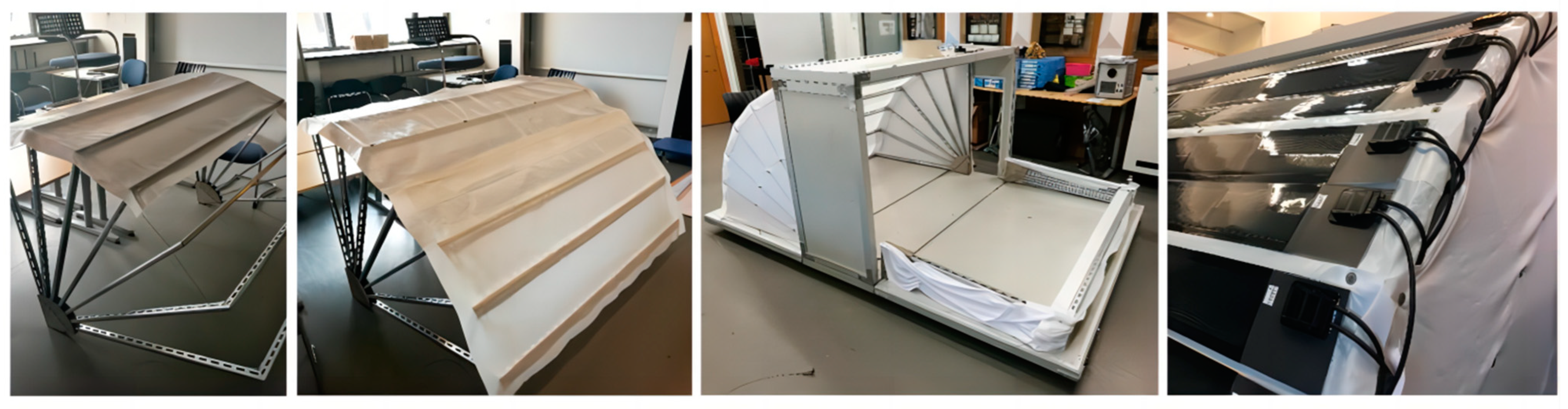
2.2. Construction of Main Structure

The primary configuration of the structural system consists of a box that is capable of being opened and closed, along with supporting rods positioned on both sides. Considering the convenience and economy of the processing design, the construction of solid models using a 1:2 equal scale.
The structural framework of the box consists of L-shaped aluminum alloy components, each measuring 50 mm × 50 mm × 5 mm, which have been joined together through welding. The box is further composed of a 50 mm thick layer of polystyrene foam board, sandwiched between two layers of colored steel plates, each measuring 0.5 mm in thickness. Additionally, the edges of the box are enveloped by C-shaped aluminum, with a cross-sectional size of 50 mm × 50 mm. In consideration of the modular assembly, the connecting portion of the enclosure and the skeleton of the box is not welded but rather fixed by bolting with right-angle stainless steel angle yards and L-connectors, which facilitates the maintenance and replacement of structure rods and link materials in the future. In order to enhance the structural integrity of the box, L-shaped industrial right-angle aluminum profiles measuring 50 mm × 50 mm are affixed externally. Steel bars are incorporated into the bottom plate as ribs to enhance the structural integrity of the plates (Figure 3).
The structural system utilizes galvanized C-beams with dimensions of 41 mm × 21 mm × 1.5 mm for the connecting rods. The connections between the rods are precisely cut at a 45° angle and secured using two distinct sizes of L-shaped stainless steel angle brackets. In order to achieve the desired fan-shaped motion during opening and closing, the wire rope is securely fastened through the connecting rods and secured with wire locks. This ensures that the angle between the two connecting rods remains at a constant degree. Additionally, a 10 mm hole is laterally cut at the bottom of each set of rods on both sides, which are then connected to the bearing box using bolts. The bearing box is a quarter-curved enclosure, constructed through the process of welding on all four sides. Each side of the box is fabricated by laser cutting a 5 mm thick steel plate. Four surfaces are offered in three different sizes, designed for the purpose of securing bars at the outermost edge (Figure 4), connecting the remaining bars using perforated bolts, and affixing the bottom of the enclosure.

2.3. Installation of the Enclosure

The PTFE film as the enclosure, measuring 1 m in width and 0.2 mm in thickness, was appropriately cut and positioned. To secure the film to the pole, holes were punched through both the film and the pole, and the film was fastened to the pole using M5 screws and nuts. The selection of spandex as the side material was motivated by the requirement to enhance room ventilation and heat exchange, while also ensuring a desired level of flexibility and elasticity. In order to mitigate the effects of rain, a nano waterproofing spray was applied to the spandex material (Figure 5). A dual-roof design was developed. The inner side of the enclosure features a detachable inner roof, which is fixed at a distance of 15 cm. The three materials used for the inner roof are canvas, polyethylene (PE), and polyvinyl chloride (PVC), respectively, which are chemically stable, lightweight, economical, and easily available, and the physical properties of materials as shown in Table 1.
A set of 10 photovoltaic modules, with each module measuring 120 mm × 1800 mm, are arranged on the unfolded surface in two sections. A 10 mm gap is intentionally left between the modules to prevent folding during the installation and recovery of the shelter. Solar panel power guarantees not less than 90% Ppm within 1 year. Standard Test Conditions are under the measurements of the electrical characteristics of the photovoltaic modules offered by the manufacturers and shown in Table 2:
-
Irradiance: 1000 W/m2;
-
Cell temperature: 25 °C;
-
Spectral distribution: AM 1.5.

3. Methodology

3.1. Theoretical Energy Model of Photovoltaic Enclosure

A portion of the incident solar radiation that is received by the photovoltaic module integrated within the shelter enclosure undergoes a conversion process, wherein a fraction is transformed into electrical energy, while the remaining portion is converted into thermal energy. The inclination angle between the photovoltaic module and the horizontal plane is denoted as θ . The expression that represents the total instantaneous incident radiation on the external surface of the photovoltaic module at various inclination angles is given by
( τ α ) i G T i = Q ( t ) ˙ + E ( t ) ˙
( τ α ) i is the constant product of the transmission and absorption coefficients derived for the hemisphere solar component of the incidence angle, which is calculated as the angle between the surface normal vector and the direction of the sun rays. G T i could be estimated based on total global horizontal irradiation ( G T ) obtainable by field measurement, elevation angle ( θ ), and the tilt angle ( i ) of the photovoltaic through the formula below:
G T i = G T × s i n ( θ + i ) s i n ( θ )
θ = s i n 1 [ s i n δ s i n φ + c o s δ c o s φ c o s ω ]
ω is the hour angle, φ is the latitude of the location, and declination δ depends on the day ( d ) of the year as follows [21]:
δ = 23.45 s i n [ 360 365 ( 284 + d ) ]
The operating temperature of the photovoltaic cell is influenced by both the heat generated by the PV module through solar radiation and the surrounding environmental conditions. The control equation for the time-dependent three-dimensional temperature field is provided below [22].
Q t ˙ = ρ c T ( x , y , z , t ) t K 2 T x , y , z , t x 2 + 2 T x , y , z , t y 2 + 2 T x , y , z , t z 2
where ρ is the density, c is the specific heat capacity, K is the thermal conductivity. The application of a simplified one-dimensional (1D) model in photovoltaic systems possesses the capability to effectively meet the accuracy requirements for predicting power generation [23]. Additionally, a 1D heat transfer model is satisfactory in describing the temperature distribution across a finite module thickness. Hence, the simplified temperature equation for the photovoltaic cell directly affixed to the shelter enclosure’s PTFE material can be expressed as
Q t ˙ = ρ c T x , t t h o u t ( T p v T a m b ) λ P T F E D P T F E ( T p v T P T F E )
Because photovoltaic efficiency is highly dependent on cell temperature under operating conditions, the generated electricity is calculated as follows [24]:
E ( t ) ˙ = η P V . r e f [ 1 ξ r e f ( T P V . c e l l T r e f ) ] × G T i
where η P V . r e f is the manufacturer-supplied reference electrical efficiency, equal to 0.15. T r e f is the reference temperature (298.15 K), and ξ r e f is the photovoltaic cell temperature coefficient for the selected product.

3.2. Experimental Apparatus and Methods

The experimental testing was conducted under winter conditions in a cold zone of China, with no heat source inside the SPES and photovoltaics facing south (Figure 6a). The testing site is situated within the premises of Tianjin University, located in China. The four tested models include a single-roof model and a double-roof model with inner roof materials of sailcloth, polyethylene, and polyvinyl chloride, respectively. The abbreviations for these models are Sref, Dsc, Dpe, and Dpvc, in that order. The examination period is scheduled to take place from 9:00 to 17:00 on four consecutive days, namely 28 January, 29 January, 30 January, and 1 February, during which the weather is sunny. The measurement sites on the enclosure are located on the outer surface and back sheet of the thin-film photovoltaic module at an angle of 37.5°, as well as on the inner surface of the enclosure. The three measurement points are all positioned along a vertical line perpendicular to the enclosure. The environmental parameters in this study involved outdoor ambient environment temperature (OAET), wind speed (WS), horizontal solar irradiance (HSI), and ambient humidity (AH).
The PC-4 portable autonomous weather station is used to record outdoor meteorological parameters. The monitoring ranges for solar irradiance, wind speed, and ambient temperature are 0 to 2000 W/m2, 0 to 70 m/s, and −50 to +100 °C, respectively. The power generation performance of thin-film photovoltaic module systems is evaluated by connecting them to the Daystar DS-100C PV I-V monitoring system (Figure 6b). The device serves as a comprehensive tool that enables instantaneous monitoring of the power output produced by the photovoltaic system, as well as the standardization of the collected data. The Yokogawa GP20 temperature logger is utilized to record real-time temperature data (Figure 6c), enabling the simultaneous measurement of multiple modules with a high degree of accuracy.

3.3. CFD Model

The simulation is based on ANSYS-Fluent, and the PISO algorithm as the pressure solver can effectively accelerate the convergence speed. RNG k-ε model is chosen as the turbulence model, which is suitable for simulating natural ventilation, air supply, and hot pressure ventilation. It is simple and efficient, with good accuracy and wide application range, and has a good effect on predicting space velocity field and temperature field.
A model is established under the same circumstances as the experimental setup to validate the ANSYS-Fluent CFD model’s accuracy. The simulation with DO radiation model incorporates the following fundamental assumptions:
-
All materials exhibit isotropic physical parameters that remain constant regardless of temperature variations;
-
The gas contained within the solar emergency relief tent exhibits the characteristic of being an incompressible fluid, and the Boussinesq assumptions are satisfied;
-
Air infiltration is not contemplated for the well-sealed thin-film photovoltaic system and building envelope;
-
The entirety of the solar radiation absorbed by thin-film photovoltaic cells that are not used to produce electricity is converted to heat.
Two error analysis indices, Mean Bias Error (MBE) and Root Mean Squared Error (RMSE), are used to evaluate the accuracy of the simulation model by comparing the simulated results to the experimental data.
M B E % = i = 1 n ( m i s i ) i = 1 n m i × 100 %
R M S E % = i = 1 n ( m i s i ) 2 n × 100 %
The measured value is denoted as m i , the simulated value as s i , and the number of measured points as n . The present study employs a calibrated model to examine the efficacy of the full-size SPES when applied in Indonesia, an economy known for its susceptibility to natural disasters. Based on the Köppen-Geiger Climate Classification, the prevailing climatic conditions in the area almost fall under the classification of Af, characterized by equatorial fully humid. The calculation was conducted using the meteorological conditions of Poso City on the summer design day, taking into account the influence of temperature, humidity, and solar radiation.
The arrangement of the measurement sites is illustrated in Figure 7. The interior space of SPES is divided into three sections, and nine measurement sites are established: the south side section with flexible thin-film photovoltaic, the north side section without photovoltaic, and the central section of the box section. The heights of the measurement points were 0.2 m, 0.6 m, and 1.7 m (Figure 7), corresponding to the lying, sitting, and standing postures, respectively. The SPEC internal space was partitioned into south, middle, and north. S-0.2 denotes the measurement point at 0.2 m height in the south, etc.

3.4. Data Analysis

3.4.1. Variance Based Analysis

The Pearson Correlation Coefficient (PCC) is a statistical measure utilized to assess the strength and direction of the linear relationship between two variables X , Y .
The function c o v ( X , Y ) is the covariance of X and Y . σ X and σ Y are the deviations of X and Y , respectively, while μ X and μ Y are the respective means. ρ X , Y ranges from +1 to −1. A value of +1 implies that X is completely positively linearly correlated to Y . A value of 0 indicates that X is not linearly correlated to Y at all, and that of −1 implies that X is completely negatively linearly correlated to Y . In most cases, X and Y show an extremely strong correlation with each other when ρ X , Y is greater than 0.8. Further, X and Y can be said to be strongly correlated to each other when ρ X , Y is greater than 0.6. The expression is given below:
ρ X , Y = c o v ( X , Y ) σ X σ Y = E [ ( X μ X ) ( Y μ Y ) ] σ X σ Y

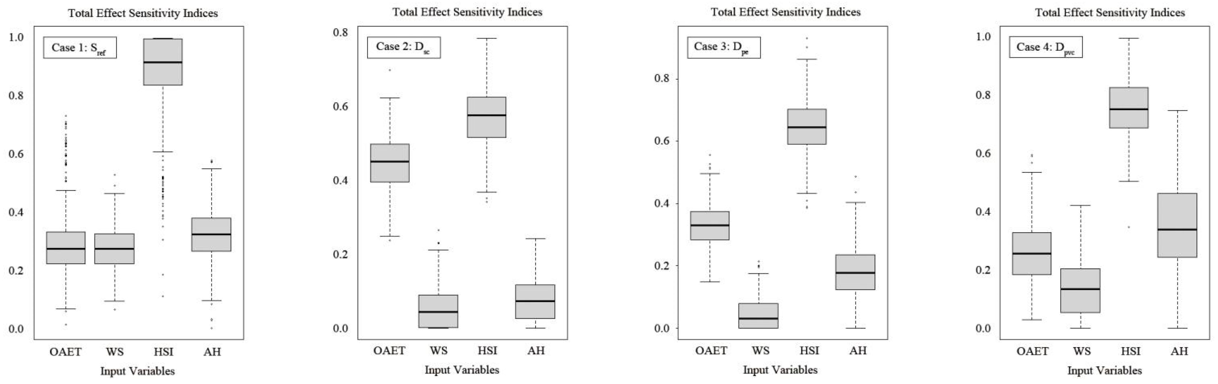
3.4.2. Sensitivity Analysis

In this study, the Sobol method based on variance decomposition was selected as the approach to evaluate the overall effects of input components. The predicted value for the input variable set x , denoted as y , is assumed to be the response generated by an engineering simulation model. Consequently, the variance decomposition can be formulated in the following [25]. It is presumed that y is the predicted value for the input variable set x and the response from a simulation model in engineering. The variance decomposition can therefore be expressed as follows:
V y = i V i + i i < j d V i j + + V 12 d
The variance of the j-th input variable’s first-order effect is denoted by V j , and V i j is the interaction term for the i-th and j-th inputs. Where d represents the sum number of all input variables. When both sides of this equation are divided by V y , the following equation results. Where S j represents the primary effect of the j-th input variable and T j represents its total influence.
j = 1 d S j + i i < j d S i j + + S 1 , , d = 1
S j = V j v a r ( z ) = v a r ( E [ z | x j ] ) v a r ( z )
T j = S j + S 1 j + + S 1 , , i , d = E [ v a r ( z | x j ) ] ) v a r z = 1 v a r E z x j v a r z

4. Experimental Study

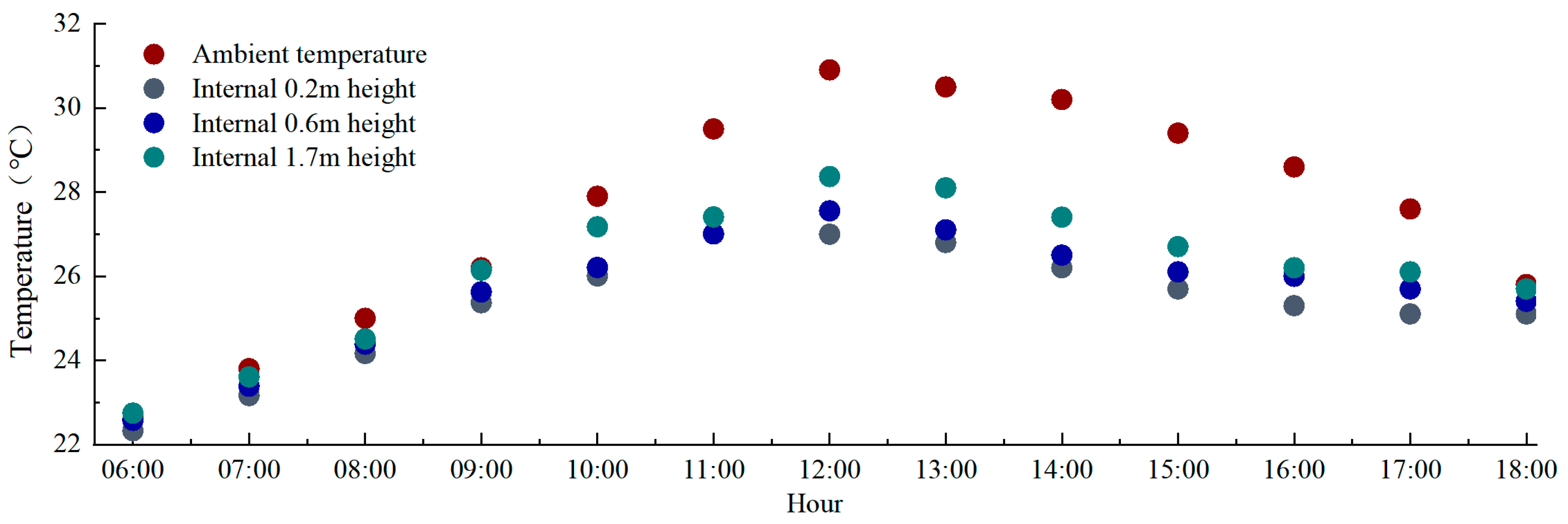
4.1. Inner Roof Interior Side Temperature

Temperature is an important index that affects indoor living comfort. Air humidity will affect the evaporation of human sweat, when the space humidity is too high, the sweat on the body surface will not evaporate, affecting the decrease in human body temperature and energy balance. Especially in disaster relief emergency buildings, the indoor temperature is generally higher than the outdoor temperature, and the emergency board houses or tents in the disaster areas are generally directly erected on the ground, the air permeability is slightly poor, and the surface water vapor evaporation leads to high indoor air humidity, further reducing the human living comfort.
The configuration form of the shelter enclosure has a direct impact on its insulation performance. A significant differentiation between solar-powered emergency shelters and conventional shelters pertains to how the internal temperature is affected. In the case of conventional shelters, the internal temperature is primarily influenced by the shelter’s capacity to withstand fluctuations in outdoor temperatures. Nevertheless, the thermal-electricity performance of the photovoltaic enclosure is subject to fluctuations based on the prevailing external climatic conditions. The thermal transfer occurring within the enclosure is analyzed by considering the disparity in temperature between the outer enclosure and the inner roof.
The temperature distribution curves observed on the inner roof of the four models exhibit parabolic shapes with downward openings (Figure 8). The maximum temperatures, occurring around 13:00, range from 31.9 °C to 36.5 °C. The variations in the gaps observed in the inner roof interior side temperature (IRIST) for the double-roofed models exhibit relatively small differences during the time period between 11:00 and 15:00. However, the IRIST demonstrates greater fluctuations for the single-roofed one, referred to as Sref. The photovoltaic module produces heat during the process of electricity generation. Consequently, there exists a substantial disparity between the IRIST and the outdoor ambient environment temperature (OAET). The maximum differences between the two parameters of Sref, Dsc, Dpe, and Dpvc are 33.3 °C, 32.9 °C, 28.1 °C, and 25.9 °C, respectively. The single-layer enclosure exhibits reduced effectiveness in mitigating temperature fluctuations, resulting in a temperature differential ranging from −5.1 °C to 0.7 °C between the exposed surface of the photovoltaic system. The temperature differential between the inner and outer layers of the double-layer shelter varies from −9.5 °C to 1.4 °C.
The analysis of variance (ANOVA) produced a statistically significant outcome, with an F-value of 19.7 and a p-value of ≤0.05. This shows that there exists a statistically significant disparity in temperature among the different varieties. The results of the quantitative analysis of the effect indicated that the Eta square (η2 value) was 0.179 based on the temperature difference, indicating that 17.9% of the variation in the data was due to the difference between the groups. It suggests that the enclosure’s construction has a significant impact on the interior surface temperature. The greater the temperature difference between the interior and exterior of a double enclosure shelter, the lower the heat transfer coefficient of the inner material. However, the construction form has a much greater influence on the difference in temperature than the inner layer material.

4.2. Electricity Power Generation

The peak power production of the four cases was seen at around 13:00. In the context of the single-top model, the temporal occurrence of peak solar irradiance aligns well with that of photovoltaic power production. In the other three double-top models, there was a delay of 1.5–2 h in the peak solar power output as shown in Figure 9. The output power of the photovoltaic system is closely related to the photovoltaic operating temperature. In the single-layer enclosure model, the Pearson Correlation Coefficient of the two is the smallest among the four models at 0.843. The correlation coefficient of Case 4 is the highest at 0.955, and the variance of the system output power is also the smallest among the four models. The main reason is that the heat transfer coefficient of PVC, the inner layer material of Case 4, is the smallest, and the change of external influences has less effect on the power.

4.3. Environmental Influences on the Operating Temperature of Photovoltaics

The operational temperature of photovoltaic systems is significantly influenced by the outdoor ambient environment temperature (OAET), wind speed (WS), horizontal solar irradiance (HSI), and ambient humidity (AH). HSI has the greatest effect on the operating temperature of thin-film photovoltaics installed outside the shelter enclosure. The primary explanation is that the photovoltaic absorbs more energy as solar irradiance increases, resulting in a substantial rise in electrical and thermal energy production. For single-layer designs, the variation in photovoltaic operating temperature is primarily attributable to varying environmental conditions, and HSI is dominant. The air layer and inner surface material contribute to the delayed heat dissipation of photovoltaics by maintaining the operating temperature stability. For the double-layer structure, Case 2 with a canvas inner layer, the degree of influence of the four meteorological parameters on the photovoltaic operating temperature is minimally different (Figure 10).

5. The Optimization of Parameter

Given the experimental data presented in the preceding section, the double-top type with canvas material provides the greatest thermal insulation. As shown in Table 3, MBE and RMSE fall within a permissible range when comparing the simulated results to the experimental data. The distance between the enclosure and inner roof of SPES, the effectiveness of mechanical ventilation, and the impact of evaporative water coolers were analyzed using CFD modeling in a thoroughly humid equatorial climate.

5.1. Normal Vertical Distance between Enclosure and Inner Roof

The air layer between the two interfaces increased the thermal resistance of indoor and outdoor heat transfer, but the thickness was not completely positively correlated with the thermal insulation effect, and a denser air layer was detrimental to structural stability. The thickness of the interlayer was increased from 0.1 m to 0.3 m, in steps of 0.05 m, for the summertime design day setting at midday (Figure 11). The transition from a single-layer enclosure to double-layer models resulted in a more pronounced decrease in temperature as the spatial position increased. As the interlayer thickness increases, each measurement site experiences a distinct degree of temperature decrease; the temperature decreases more quickly as the interlayer thickness increases from 0.1 m to 0.2 m and less swiftly as it increases from 0.2 m to 0.3 m. In consideration of the enclosure’s structural integrity and thermal insulation performance, the air interlayer is recommended to have a thickness of 0.2 m.

5.2. Influence of Mechanical Ventilation

The benefit of mechanical ventilation is that it can maintain a constant ventilation rate within a space. Natural air enters through the bottom inlet of the interlayer between the inner top and outer enclosure and exits via the top fan, whose output ranges from 0.1 to 0.6 m3/s. As the air volume increases from 0.1 m3/s to 0.3 m3/s, the temperatures at all internal measurement points decrease progressively. When the volume of exhaust air was continuously increased from 0.3 m3/s to 0.5 m3/s, the temperature of the measurement site at a height of 0.2 m continued to decrease, while the other interior temperatures remained relatively stable. The data indicate that the mechanical ventilation rate influences the indoor temperature distribution to some extent, but there are extreme values (Figure 12). In the absence of an external cooling source and relying solely on the introduction of outdoor air to cool the tent interior, the interior temperature can only be reduced to a degree close to the ambient temperature and cannot be reduced further, and the indoor thermal environment is strongly influenced by the outdoor environment.

5.3. Top Mechanical Ventilation Coupled Evaporative Cooler

To further cool the indoor space, an evaporative cooler is used to cool the air entering the double-top interlayer, with the inlet air temperature being the outdoor wet-bulb temperature, and the top fan is activated to perform mechanical exhaust, with a fan exhaust volume of 0.5 m3/s. From 6:00 to 18:00 on the summer design day, the average temperatures at various measurement sites at various heights are displayed. Based on the measured data, there is little difference between indoor and external temperatures prior to 9:00 a.m., and the higher the outdoor temperature, the clearer the benefits of the technology become. The indoor temperature at a height of 0.2 m was the lowest, with a maximum difference of 4 °C from the outdoor ambient temperature, and the highest temperature was 27 °C. The indoor temperature reached its peak at noon. The highest recorded internal temperature, observed at noon, was 28.37 °C, measured at a vertical elevation of 1.7 m (Figure 13). The temperature is within the humanly acceptable range. During this time, the temperatures of the five groups of photovoltaic cells decreased by 14.5 °C, 16.3 °C, 15.7 °C, 14.1 °C, and 12.2 °C, respectively, and the photovoltaic all-day system generated a total of 3.010 kWh.

6. Conclusions

This paper proposes a quick-buildable shelter design scheme based on a lightweight modular design that innovatively integrates thin-film photovoltaic technology into the shelter module, and a solid model of the solar-powered emergency shelter (SPES) is constructed. The key contributions of this study are summarized below.
(1)
A series of concepts and methods of SPES from design to construction are elaborated in detail, beginning with the overall design conceptualization, followed by the construction of the main structure, and then with the installation of the enclosure for the 1:2 solid model. A single-roof model and three double-roof models with inner roof materials of sailcloth, polyethylene, and polyvinyl chloride, respectively, were also developed in order to investigate electrothermal performance.
(2)
In winter conditions in China’s cold zone, experimental results show that the maximum differences between the inner roof interior side temperature (IRIST) and the outdoor ambient environment temperature (OAET) for Sref, Dsc, Dpe, and Dpvc are 33.3 °C, 32.9 °C, 28.1 °C, and 25.9 °C, respectively.
(3)
The construction form of the enclosure has a statistically significant impact on the interior surface temperature based on the analysis of variance (ANOVA). Variation in photovoltaic operating temperature for single-layer designs is mainly attributable to varying environmental conditions, with horizontal solar irradiance predominating. The influence of the outdoor ambient environment temperature (OAET), wind speed (WS), horizontal solar irradiance (HSI), and ambient humidity (AH) on the photovoltaic operating temperature is marginally different for the double-layer structure with a canvas interior layer designated as Case 2.
(4)
The design parameters of SPES were optimized for typical summer operation situations in Poso City, Indonesia, characterized by equatorial humid climatic conditions, by a CFD model that was confirmed with experimental data. Based on the available data, it is recommended that the air interlayer be 0.2 meters thick. When the exhaust air volume was gradually increased from 0.3 m3/s, the indoor temperature remained stable with the exception of the measurement site at a height of 0.2 m, where the temperature continued to decrease. Mechanical ventilation rates have a limited effect on room temperature distribution, and coupled evaporative conditioners can further reduce room temperatures effectively.
In conclusion, the issue of post-disaster resettlement has been a constant concern because of the potential for secondary harm to the physical and psychological well-being of the victims. In view of the shortage of existing shelters, a novel design for a solar-powered emergency shelter with flexible photovoltaics is proposed and investigated in this paper. SPES are designed based on ergonomic and easy open-and-close requirements. A solid model was constructed, and measurements and simulations were employed for testing the dynamic fluctuation of the interface temperature of the enclosure and the electrical performance of three double-top SPES. This research has been limited to two specific climatic zones. However, considering that the design parameters and electrical and thermal performance of SPES are directly influenced by the climatic environment, it is necessary to expand the scope of the applicability study to include a wider range of climatic conditions.

Author Contributions

Methodology, T.L.; Resource, T.L.; Formal analysis, B.L.; Project administration, B.L.; Investigation, R.L.; Validation, R.L.; Supervision, L.Z.; Formal analysis, Y.H.; Writing—original draft, Y.H.; Writing—review and editing, T.L., B.L., R.L., L.Z., Y.H. and M.J. All authors have read and agreed to the published version of the manuscript.

Funding

This work was sponsored by China Yangtze Power Co., Ltd. (No. Z152302009/Z612302004). The funding sponsors had important roles in the design of the study and in the decision to publish the results.

Data Availability Statement

The data that has been used is confidential.

Conflicts of Interest

Author Tiangang Lv, Bing Liu and Rujie Liu are employed by the company Three Gorges Electric Energy Co, Ltd. The remaining authors declare that the research was conducted in the absence of any commercial or financial relationships that could be construed as a potential conflict of interest.

Nomenclature

SPESsolar-powered emergency shelter
IRISTinner roof interior side temperature
OAEToutdoor ambient environment temperature
MBEMean Bias Error
RMSERoot Mean Squared Error
ANOVAanalysis of variance
WSwind speed
HIShorizontal solar irradiance
AHambient humidity
Srefsingle-roof case
Dscdouble-roof case with sailcloth as inner roof
Dpedouble-roof case with polyethylene as inner roof
Dpvcdouble-roof case with polyvinyl chloride as inner roof

References

  1. Johnson, C. What’s the big deal about temporary housing? Planning considerations for temporary accommodation after disasters: Example of the 1999 Turkish earthquakes. In Proceedings of the 2002 TIEMS Disaster Management Conference, Waterloo, ON, Canada, 14 May 2002. [Google Scholar]
  2. Quarantelli, E.L. Patterns of sheltering and housing in US disasters. Disaster Prev. Manag. 1995, 4, 43–53. [Google Scholar] [CrossRef]
  3. Regan, P. Interim Housing Provision Following Earthquake Disaster; Springer: Berlin/Heidelberg, Germany, 2015; pp. 1237–1254. [Google Scholar]
  4. Fuji, G. Japan’s Disaster Response System; China Architecture Publishing & Media Co., Ltd.: Beijing, China, 2003. [Google Scholar]
  5. Asfour, O.S. Learning from the past: Temporary housing criteria in conflict areas with reference to thermal comfort. Int. J. Disaster Risk Reduct. 2019, 38, 101206. [Google Scholar] [CrossRef]
  6. Editorial Board of the Journal. For the Memorial of “May 12”-Crossing: Dialogues for Emergency Architecture. Chin. Art Dig. 2009, 4, 66–67. [Google Scholar]
  7. Thapa, R.; Rijal, H.B.; Shukuya, M.; Imagawa, H. Study on the wintry thermal improvement of makeshift shelters built after Nepal earthquake 2015. Energy Build. 2019, 199, 62–71. [Google Scholar] [CrossRef]
  8. Wang, Y.; Wang, L.; Long, E.; Deng, S. An experimental study on the indoor thermal environment in prefabricated houses in the subtropics. Energy Build. 2016, 127, 529–539. [Google Scholar] [CrossRef]
  9. Kim, J.G.; Lee, J.; Ahn, B.L.; Shin, H.; Yoo, S.; Jang, C.Y.; Song, D.; Kim, J. Indoor Thermal Environment of Temporary Mobile Energy Shelter Houses (MeSHs) in South Korea. Energies 2015, 8, 11139–11152. [Google Scholar] [CrossRef]
  10. Zhang, L.; Meng, X.; Liu, F.; Xu, L.; Long, E. Effect of retro-reflective materials on temperature environment in tents. Case Stud. Therm. Eng. 2017, 9, 122–127. [Google Scholar] [CrossRef]
  11. Salvalai, G.; Imperadori, M.; Scaccabarozzi, D.; Pusceddu, C. Thermal performance measurement and application of a multilayer insulator for emergency architecture. Appl. Therm. Eng. 2015, 82, 110–119. [Google Scholar] [CrossRef]
  12. Marin, P.; Saffari, M.; de Gracia, A.; Zhu, X.; Farid, M.M.; Cabeza, L.F.; Ushak, S. Energy savings due to the use of PCM for relocatable lightweight buildings passive heating and cooling in different weather conditions. Energy Build. 2016, 129, 274–283. [Google Scholar] [CrossRef]
  13. Wang, C.; Huang, X.; Deng, S.; Long, E.; Niu, J. An experimental study on applying PCMs to disaster-relief prefabricated temporary houses for improving internal thermal environment in summer. Energy Build. 2018, 179, 301–310. [Google Scholar] [CrossRef]
  14. Samani, P.; Leal, V.; Mendes, A.; Correia, N. Comparison of passive cooling techniques in improving thermal comfort of occupants of a pre-fabricated building. Energy Build. 2016, 120, 30–44. [Google Scholar] [CrossRef]
  15. Maghami, M.R.; Maghoul, A.; Dehkohneh, S.S.; Gomes, C.; Hizam, H.; Othman, M.L.B. Hybrid renewable energy as power supply for shelter during natural disasters. In Proceedings of the 2016 IEEE International Conference on Automatic Control and Intelligent Systems, I2CACIS 2016, Selangor, Malaysia, 22–22 October 2016; IEEE: Piscataway, NJ, USA, 2017. [Google Scholar]
  16. Hendarti, R.; Katarina, W.; Wangidjaja, W. The study of the application of crystalline silicone solar cell type for a temporary flood camp. IOP Conf. Ser. Earth Environ. Sci. 2017, 109, 012040. [Google Scholar] [CrossRef]
  17. Cornaro, C.; Sapori, D.; Bucci, F.; Pierro, M.; Giammanco, C. Thermal performance analysis of an emergency shelter using dynamic building simulation. Energy Build. 2015, 88, 122–134. [Google Scholar] [CrossRef]
  18. Brandhorst, R. Solar-powered, modular, emergency/disaster response housing. In Proceedings of the Photovoltaic Specialists Conference, Philadelphia, PA, USA, 7–12 June 2009; IEEE: Piscataway, NJ, USA, 2009. [Google Scholar]
  19. Higier, A.; Arbide, A.; Awaad, A.; Eiroa, J.; Miller, J.; Munroe, N.; Ravinet, A.; Redding, B. Design, development and deployment of a hybrid renewable energy powered mobile medical clinic with automated modular control system. Renew. Energy 2013, 50, 847–857. [Google Scholar] [CrossRef]
  20. Dhere, N.G.; Schleith, S. Reliability of hybrid photovoltaic DC micro-grid systems for emergency shelters and other applications. In Proceedings of the Spie Solar Energy + Technology, San Diego, CA, USA, 17–21 August 2014; p. 91790F. [Google Scholar]
  21. Barroso, J.S.; Barth, N.; Correia, J.P.M.; Ahzi, S.; Khaleel, M.A. A computational analysis of coupled thermal and electrical behavior of PV panels. Sol. Energy Mater. Sol. Cells 2016, 148, 73–86. [Google Scholar] [CrossRef]
  22. Aly, S.P.; Ahzi, S.; Barth, N.; Abdallah, A. Using energy balance method to study the thermal behavior of PV panels under time-varying field conditions. Energy Convers. Manag. 2018, 175, 246–262. [Google Scholar] [CrossRef]
  23. Bevilacqua, P.; Perrella, S.; Bruno, R.; Arcuri, N. An accurate thermal model for the PV electric generation prediction: Long-term validation in different climatic conditions. Renew. Energy 2021, 163, 1092–1112. [Google Scholar] [CrossRef]
  24. Skoplaki, E.; Palyvos, J.A. On the temperature dependence of photovoltaic module electrical performance: A review of efficiency/power correlations. Sol. Energy 2009, 83, 614–624. [Google Scholar] [CrossRef]
  25. Tian, W.; Yang, S.; Zuo, J.; Li, Z.; Liu, Y. Relationship between built form and energy performance of office buildings in a severe cold Chinese region. Build. Simul. 2016, 10, 11–24. [Google Scholar] [CrossRef]
Figure 1. Design parameters of SPES. (a) Section view, (b) SPES plan.
Energies 17 00118 g001
Figure 2. Configuration and connection of the box and the opening–closing skeleton.
Energies 17 00118 g002
Figure 3. Box production process.
Energies 17 00118 g003
Figure 4. Production of opening–closing skeleton.
Energies 17 00118 g004
Figure 5. Enclosure installation procedures.
Energies 17 00118 g005
Figure 6. Experimental platform and main data monitoring equipment. (a) Experimental platform. (b) Daystar DS-100C photovoltaic I-V monitoring system. (c) The Yokogawa GP20 temperature logger.
Energies 17 00118 g006
Figure 7. Arrangement of measurement points in simulation.
Energies 17 00118 g007
Figure 8. Temperature change curve during test period.
Energies 17 00118 g008
Figure 9. Relationship between global horizontal irradiation and system output power.
Energies 17 00118 g009
Figure 10. Total effect sensitivity analysis on the operating temperature of photovoltaics.
Energies 17 00118 g010
Figure 11. Temperature comparison of measuring points with different interlayer thicknesses.
Energies 17 00118 g011
Figure 12. The variation curve of indoor temperature with the change of mechanical exhaust air volume.
Energies 17 00118 g012
Figure 13. Temperature variation of SPES with top mechanical ventilation coupled evaporative cooler.
Energies 17 00118 g013
Table 1. The physical properties of materials used for the inner surface of double-roof SPES.
MaterialInternal ViewSmoothnessThicknesses (mm)Density
(kg/m3)
Thermal Conductivity
(W/(m·K))
SailclothEnergies 17 00118 i001Worse0.321400.23
PolyethyleneEnergies 17 00118 i002General0.313900.14
Polyvinyl chlorideEnergies 17 00118 i003General0.39600.42
Table 2. Thin-film photovoltaic modules electrical features.
ParametersUnitParametersUnit
Solar Cell TypeCIGSOpen Circuit Voltage (Voc)10.89 +/− 1 V
Maximum Power Output (Pmax)21.87 +/− 2 WShort Circuit Current (Isc)1.40 +/− 0.2 A
Voltage at Maximum Power Point (Vmpp)8.83 +/− 1 VOperating Temperature−10 °C~45 °C
Current at Maximum Power Point (Impp)2.48 +/− 0.2 AEfficiency15%
Table 3. MBE and RMSE of studied models.
Single RoofDouble Roof
MBE 1%1.4%
RMSE18.7%17.2%
Disclaimer/Publisher’s Note: The statements, opinions and data contained in all publications are solely those of the individual author(s) and contributor(s) and not of MDPI and/or the editor(s). MDPI and/or the editor(s) disclaim responsibility for any injury to people or property resulting from any ideas, methods, instructions or products referred to in the content.

