1. Introduction
In recent years, there have been a significant rise in the worldwide population and increasing industrial development, leading to worrisome consequences for global energy demand and supply [
1]. The limited availability of traditional fossil fuels, the potential threat they pose to life on Earth, and their detrimental impact on the environment necessitate more regulations and restrictions. The current energy framework demands advancements in the realm of clean and sustainable energy [
2]. In contemporary times, green energy sources have assumed a pivotal role in promoting clean energy generation devoid of carbon emissions while also fostering environmentally friendly practices and ensuring sustainability in the environment [
3]. In this context, a dependable, renewable, and emission-free clean energy source that can be found everywhere and is available around the year is solar radiation. Solar radiation can be transformed into electricity using several methods. Using solar chimney power plants is one way to turn solar energy into electricity [
1]. Furthermore, it has been proven that solar energy can be converted into cold for cooling and refrigeration purposes [
4]. For instance, in adsorption-based cooling and refrigeration systems, solar energy has been used to release refrigerant vapor from the adsorption bed [
5].
The production of ice from the heat of the sun is no longer regarded as a magical or astonishing phenomenon in contemporary technology. It is well known that the energy from the sun has been harnessed for the purpose of powering chillers and freezers that rely on thermal energy for their operation. Heat-powered cold-generating systems encompass steam ejector units, absorption ice makers, and solid sorption cold-producing equipment. Sunlight-driven cooling technologies utilize the sun’s heat to run the cooling cycle by means of collection or focusing [
6]. Vapor adsorption cooling and freezing systems have emerged as a highly appealing approach within the realm of heat-driven refrigeration systems. Currently, adsorption technology is widely acknowledged for its practicality, environmental friendliness, and energy efficiency in harnessing low-grade and ultra-low-grade heat [
7] to attain various beneficial outcomes at the level of domestic as well as industrial applications [
8].
It is noteworthy to point out that in contrast to the absorption-based and steam ejector cooling cycles, the adsorption-based cold-generating cycle has the advantage of using low-grade heating energy. For instance, the generation of coolant gas from the adsorption bed can be achieved by utilizing a heating source with a temperature of 50 °C, particularly when employing silica gel as an adsorption medium with water as the coolant fluid [
9]. The aforementioned statement highlights the appeal of researching solar-powered adsorption-based cold-generating devices [
10]. Within the realm of the scholarly literature, numerous investigations have been undertaken to explore, enhance, and modify these systems with experimental, theoretical, or combined approaches [
11,
12,
13,
14,
15]. Furthermore, there are a considerable number of studies on the effective implementation of low-quality thermal energy sources other than solar energy. These investigations include the manipulation of geothermal energy [
16] and industrial waste heat [
17,
18].
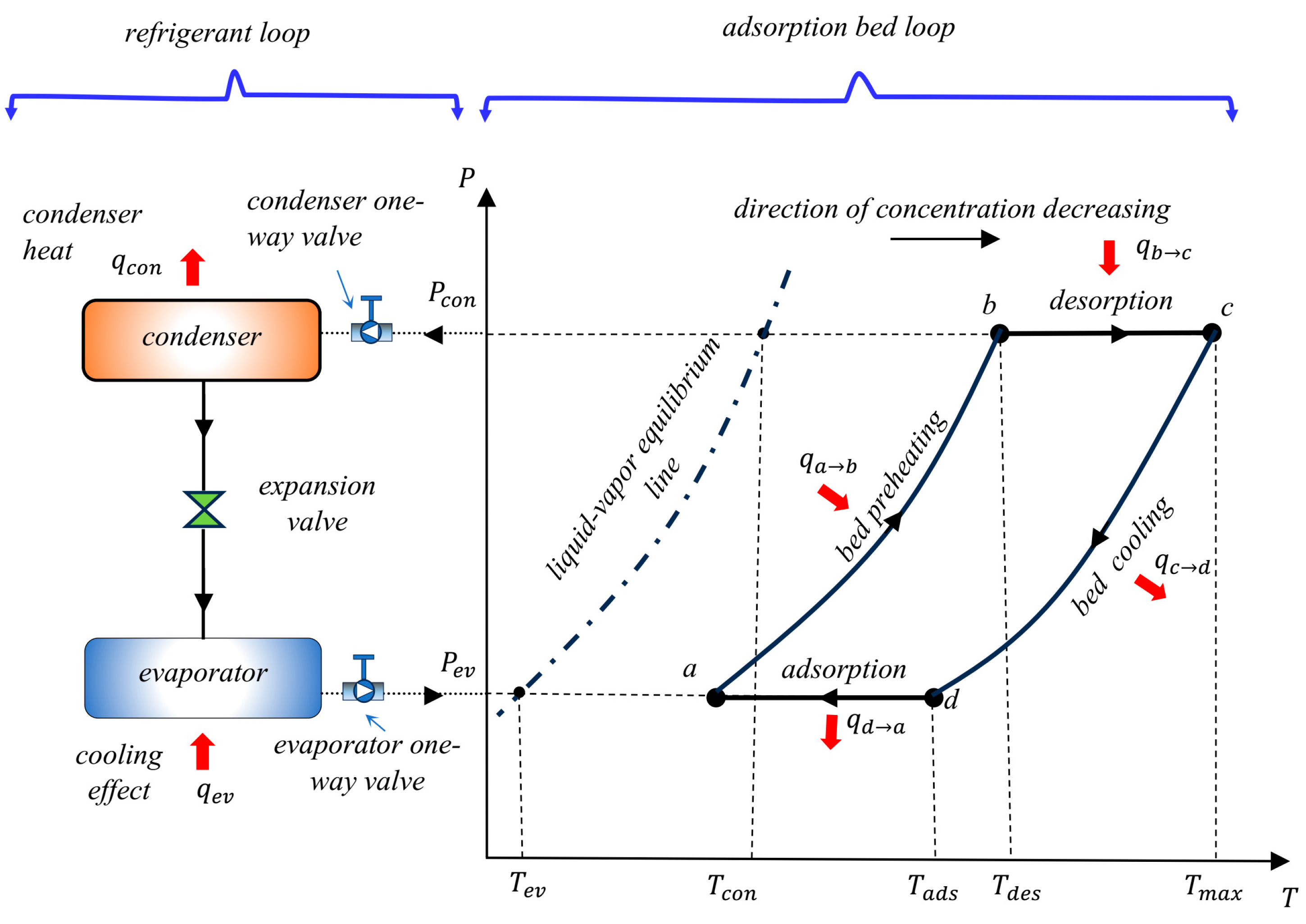
The adsorption cooling operating cycle bears resemblance to the vapor compression cooling cycle, albeit with a distinct variation in the operation of the compression operation. Instead of a mechanical compressor like in vapor compression systems, the adsorption bed in the adsorption refrigeration cycle works as a compressor that is powered by heat [
3]. The adsorption bed comprises a solid adsorption medium and a coolant gas. Activated carbon, silica gel, and zeolite are frequently employed as adsorption materials [
19]. Methanol, ammonia, and water are frequently employed as coolant fluids. Enhancing the adsorption uptake capability of the adsorbent substances is a crucial prerequisite for the efficient and cost-effective functioning of adsorption-based cooling technologies [
12]. Many studies have been conducted on the practical application of vapor adsorption cold-producing technology. Examples of the previous research studies include ice makers [
20,
21,
22], vaccine refrigerators [
23,
24], building heating and cooling applications [
25,
26,
27,
28], automotive air-conditioning applications [
18,
29], storage of food and agricultural products [
30,
31,
32], and others.
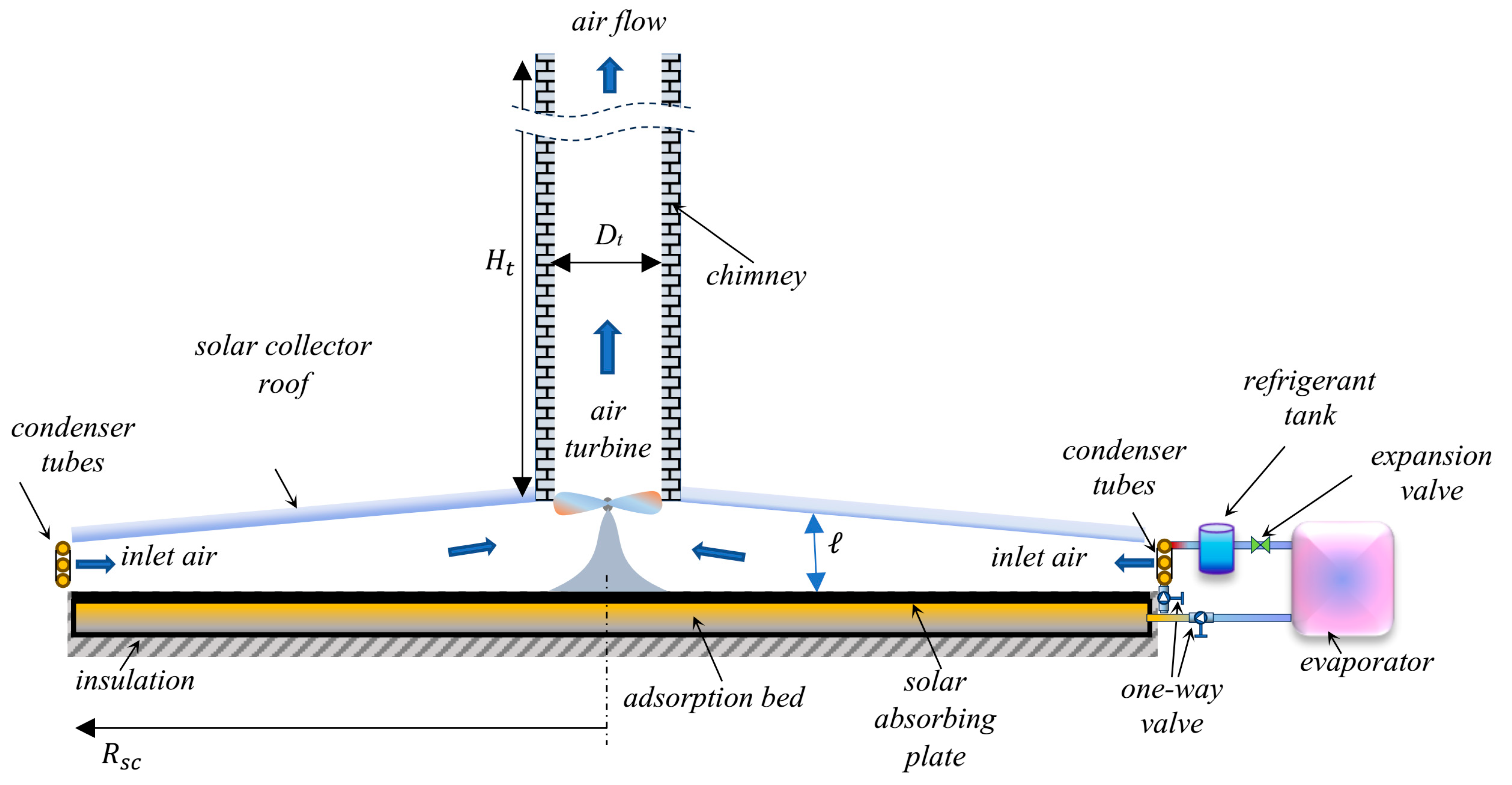
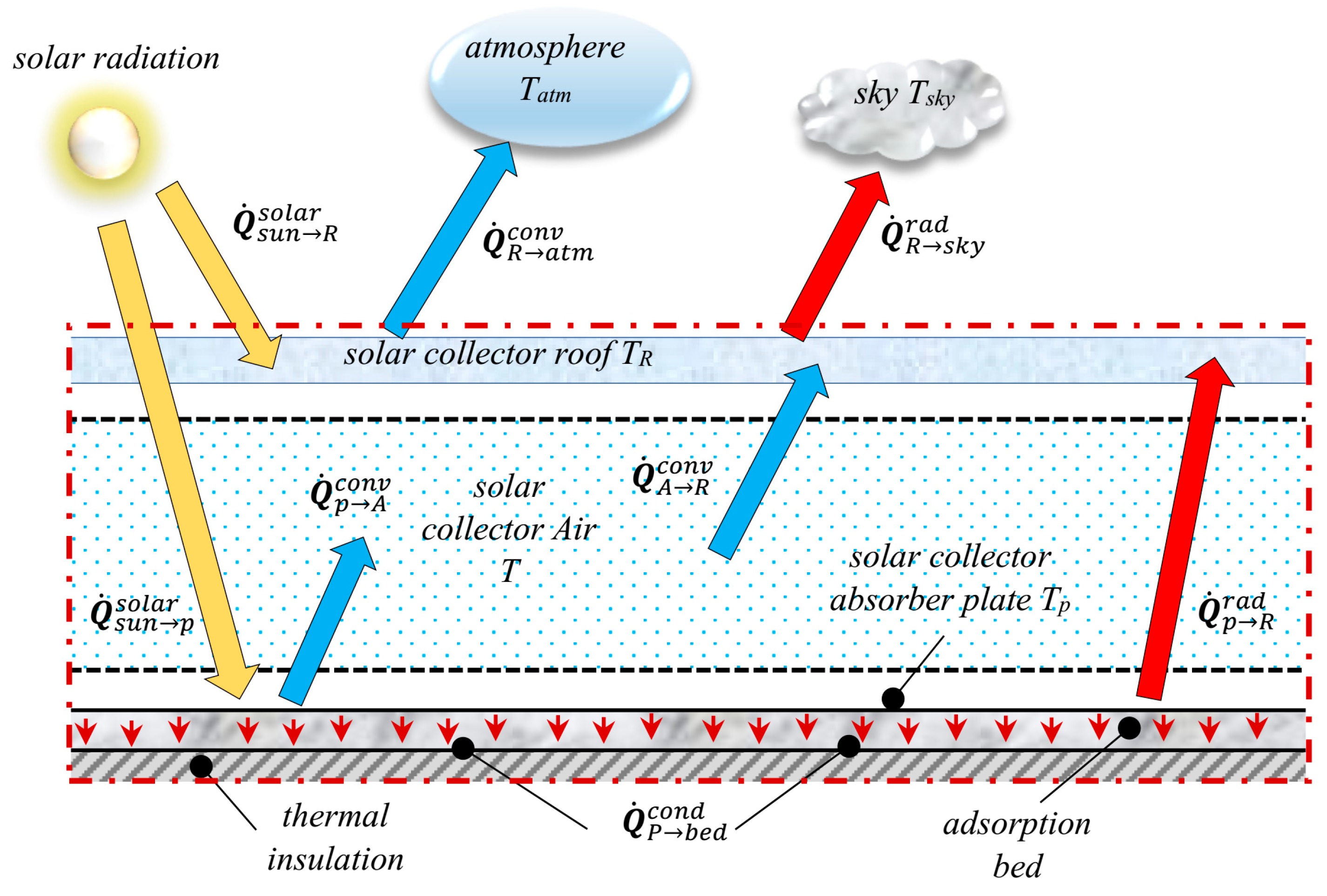
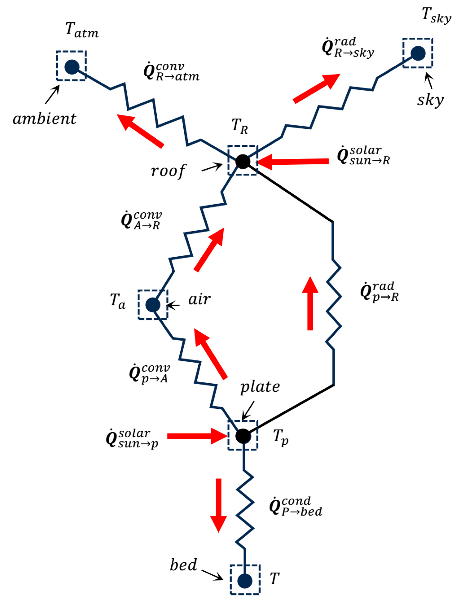
The solar chimney power plant, also known as the solar updraft tower power plant, is a relatively simple and environmentally friendly approach to harnessing solar energy to produce electricity. The standalone solar updraft tower power plant comprises various essential components, namely, a chimney, a solar radiation absorber plate, the collector roof, an air turbine, and an electric generator. The conversion of solar energy into thermal energy takes place through a set of operations involving the collecting surface and absorber, leveraging the greenhouse effect. The absorber transfers thermal energy to the airflow, which is then converted into kinetic energy by the air turbine situated at the entrance of the chimney [
33]. Solar chimney power systems have the capability to function independently, presenting a viable solution for distant locations and regions with restricted power grid accessibility. Moreover, these systems have minimum operational and maintenance costs, further enhancing their suitability for such locations. Nevertheless, standalone solar updraft tower power plants are dependent on direct solar radiation, hence imposing restrictions on electricity generation exclusively during daylight hours [
33]. Furthermore, although standalone solar chimneys with some heat storage in the ground can work during the day and night, power generation during the nighttime is significantly lower, and power interruptions are seen periodically [
34]. Moreover, the implementation of such technology is confronted with a significant obstacle, namely, the issue of low solar-to-electricity conversion efficiency, impeding its progress towards widespread industrialization. As an example, the initial operational prototype of the Manzanares experimental plant in Spain, established in 1982, exhibited a solar-to-electricity conversion ratio below 0.1% [
35].
Following the construction of the initial solar chimney power plant prototype in Manzanares, Spain, a multitude of studies have been undertaken with the aim of enhancing the operational efficiency of solar updraft tower power plants [
36]. Efforts were made by researchers to enhance the performance of conventional standalone solar chimney power plant systems by modifying the system components’ design [
37,
38,
39,
40,
41] and optimizing the system parameters [
42,
43]. The conversion efficiency of a solar updraft tower power plant is influenced by several geometric parameters [
44,
45]. These parameters include the profile of the chimney, the angle at which the chimney diverges, and the angle of the collector roof [
46,
47]. These parameters have a direct impact on the overall performance of the plant [
48].
Tingzhen et al. [
49] conducted a comprehensive mathematical study of the Manzanares power plant. The characteristics examined by the investigators encompassed system efficiency, the generation of power, and driving forces. The research results revealed that the driving force of a solar chimney power plant is contingent upon the chimney’s height as well as the solar radiation. Kasaeian et al. [
50] and Yapıcı et al. [
51] came to the same conclusions on the plant efficiency gain, that is, that it is brought about by a chimney height increase. A numerical study on solar updraft tower power plants was carried out by Hu et al. [
52], who investigated a divergent chimney with a divergent outlet as well as a cylindrical chimney with a divergent input. When compared with the cylindrical chimney, the divergent chimney was found to perform significantly better. In addition to this, Milani et al. [
53] presented theoretical research and carried out a parametric study in order to find out the highest possible power production of the studied solar updraft tower power plant. The impact of collector inlet height on performance was investigated by Ghalamchi et al. [
54]. They found that the act of reducing the height of the intake was seen to enhance performance; nevertheless, overly diminished heights could result in a deterioration in performance. The chimney wall profile is a characteristic that has been investigated for its impact on flow pattern and solar chimney power plant efficiency [
55]. In their study, Saad et al. [
36] conducted a numerical investigation to examine the impact of the chimney wall profile and the collector roof angle. The study revealed that the utilization of an inner parabolic chimney profile led to enhanced performance compared with systems employing outer parabolic chimneys. In another study, Hu et al. [
56] conducted an investigation into the impact that a guide wall has on the performance of a solar chimney power plant. They observed that the addition of a guide wall results in a reduction in the mass flow rate. In a further study, it was determined, in [
57], that there is no optimal ground slope angle for attaining maximum power extraction. According to Sundararaj et al. [
58], they used a reduced-scale model to conduct an experiment on the performance of an inclined collector connected to a divergent chimney. In more research, numerical analysis was used to look into how the angle of the solar collector roof affects the performance and efficiency of a solar updraft tower power plant [
59]. In their work, Mandal et al. [
60] put out a proposal to modify the surface of the absorber of a solar updraft tower power plant by incorporating several triangular wavy peaks with varying amplitudes.
In order to optimize the consumption of solar energy and address the aforementioned constraints pertaining to standalone solar updraft tower power plants, the notion of hybridization has emerged as an efficient approach for solar chimney power plants [
61]. Numerous efforts have been made by researchers to boost the performance of conventional standalone solar chimney power systems with the integration of various energy conversion technologies. Many solar chimney hybridizing approaches have been suggested, encompassing the incorporation of geothermal energy [
62,
63], water desalination systems [
64,
65,
66,
67], solar photovoltaic cells [
66,
68,
69], waste heat systems [
70], solar ponds [
71], heat exchangers [
72], cooling towers [
73,
74], and others [
33]. Several previous studies have attempted to mitigate the issue of intermittent power generation in solar chimneys using various approaches. In a study by Habibollahzade et al. [
75], the integration of a solar chimney power plant and geothermal well was considered a workable solution to reducing the intermittent power generation associated with solar chimneys. Consequently, the hybrid system was implemented with the intention of utilizing solar energy during the day and geothermal energy during the night. Additional techniques for storing solar heat include the utilization of water bags [
76], the incorporation of phase change material [
77,
78], the implementation of specialized soil types with high heat storage capabilities [
79], and the utilization of solar ponds [
80]. Nevertheless, it is important to note that the existing approaches discussed above do not offer a comprehensive solution to addressing the issue of inconsistent power output in solar chimneys [
75].
The integration of a solar chimney power plant with a power station can enhance the overall efficiency of the integrated system and mitigate the environmental consequences associated with the disposal of waste heat. A better strategy might involve integrating waste heat from a power plant with a solar updraft tower power plant [
33] as opposed to discharging it into a cooling tower. The study conducted by Zandian and Ashjaee [
74] involved the integration of a dry cooling tower with a solar updraft tower power station to enhance the thermal efficiency of a fossil fuel steam power plant. Similarly, in nuclear power plants, the excess thermal energy generated throughout the nuclear cycle can be harnessed to elevate the temperature of the air within the collector. Hence, this results in enhancing the electricity generation capacity of the solar chimney power plant. In arid climates, solar chimney power plants can be utilized as dry cooling towers, thereby generating supplementary electrical power. In an effort to enhance the overall efficiency of nuclear power stations, Fathi et al. [
81] implemented a strategy to recycle the waste heat generated by a nuclear power station and subsequently employed this heat in a solar updraft tower power plant. In another attempt to exploit waste heat from industrial processes, a study to assess the viability of a combined hybrid solar chimney power plant with a gas turbine was conducted by Djimli et al. [
82]. The recovery of energy from the exhaust gas of the gas turbine power station was achieved by injecting the gas either at the inlet or in the center of the collector. This injection method facilitated a rapid increase in efficiency. Shahdost et al. [
83] endeavored to hybridize and enhance the standalone updraft chimney power system by utilizing the exhaust flue gases produced by fossil fuel combustion processes in power stations. Aliaga et al. [
72] undertook a comprehensive investigation, encompassing both theoretical and experimental aspects, in order to evaluate the performance of a modified solar chimney power plant. The solar chimney power system was modified by replacing the conventional solar collector with a heat exchanger positioned within the central portion of the chimney. Flat mirrors were positioned outside to concentrate solar radiation, and they provided heat to the heat exchanger inside the chimney. A higher power density was achieved in contrast to the previous prototypes published in the literature that are based on the conventional solar chimney power system [
72].
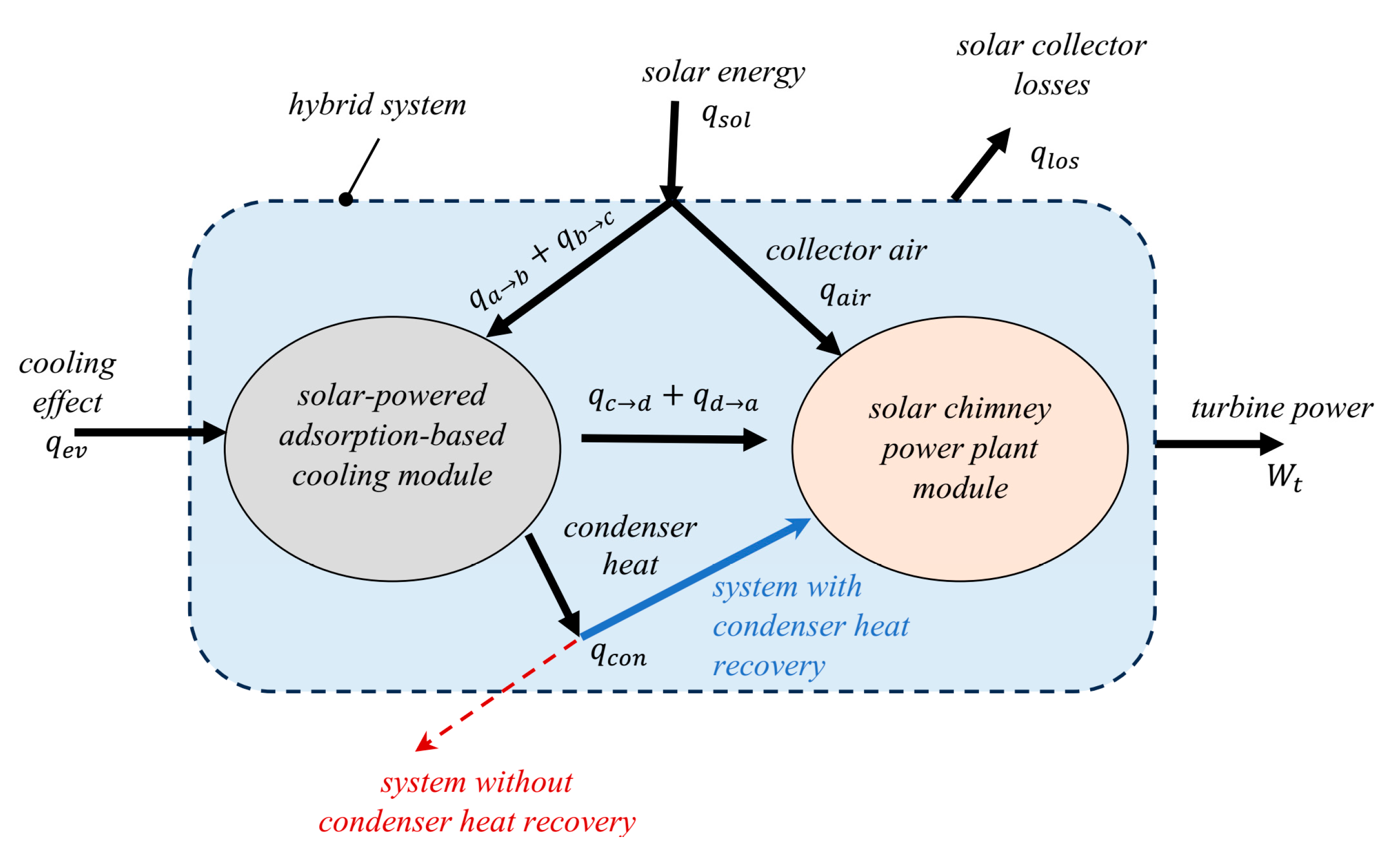
In a prior study [
3], a novel hybrid solar chimney power system that integrates a solar-driven adsorption-based water cooler was presented. The primary aim of the introduced system was to enhance the utilization of solar energy by effectively harnessing and recycling the thermal energy emitted by the adsorption reactor, thereby augmenting the power generation of the plant. Upon comparing the newly introduced technology with conventional standalone solar chimney power plants, it was seen that the introduced system demonstrated the capability to provide continuous and uninterrupted power supply throughout the entirety of the day. The findings indicated that a substantial percentage, around 62.6%, of the thermal energy produced by the adsorption reactor could be efficiently reclaimed. Therefore, a notable increase of 3.22% in turbine power was observed when the efficiency of converting solar energy to electricity reached 0.4%. However, further modifications to the design and operation of the previous system could be implemented in order to boost its performance even more. Consequently, the primary aim of this present paper is to present a modified version of the previously studied system in [
3]. The reason for applying the modification is to optimize the utilization of solar energy by harnessing and reusing the heat of condensation emitted by the condenser. This objective is pursued in order to augment power generation and improve the performance parameters of the hybrid system.
6. Results and Discussion
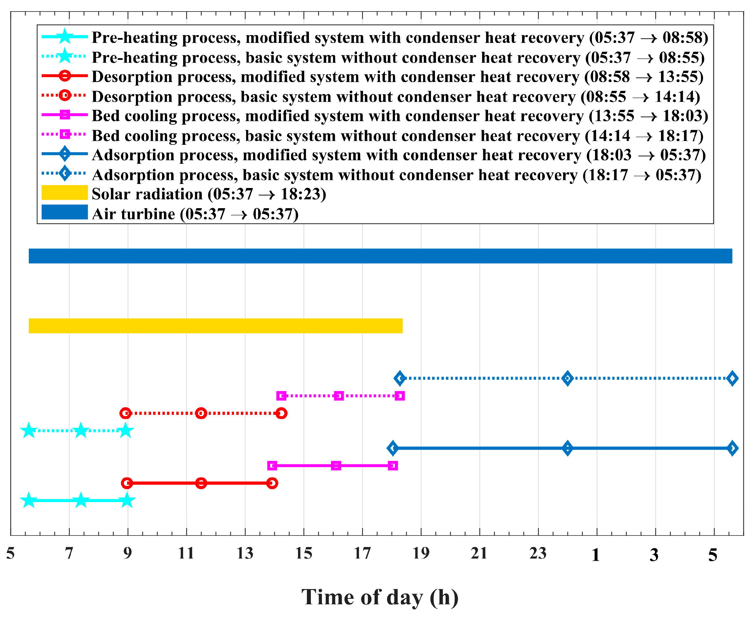
The presented results comprise the performance and operation behavior of the combined solar chimney power plant and adsorption cooling system in two cases: the modified system that retrieves condenser heat and the basic system without condenser heat regaining. The time allocation, schedule of the different system operations, and periods of various cycle processes are illustrated by the timeline chart in
Figure 7 for the presented modified system, with condenser heat retrieval, and the original basic system, without heat recapture. The complete cycle of both the modified and basic systems begins at sunrise at 05:37 and continues the operation for a period of 24 h. Solar radiation extends from 05:37 to 18:23 for a period of 12.77 h and reaches its peak of
at 11:00. The total solar thermal energy that falls on the solar collector roof is found to be
during the system operating cycle. The operation of the air turbine extends over the whole 24 h period of the operating cycle in both the modified system and the basic system. It is obvious that the adsorption bed-preheating–pressurization process comes before the desorption and condensation processes. The notion that the adsorption reactor-preheating–pressurization process is not influenced by condenser heat recapture is not accurate. As presented by the timeline chart in
Figure 7, the preheating–pressurization process of the adsorption rector is found to be 3 min longer in the case of the modified system compared with the basic system. This is because the amount of refrigerant mass inside the adsorption bed of the system with condenser heat recirculation is smaller than the corresponding amount for the basic system. The desorption and condensation processes for the modified system with condenser heat reuse continue for 4.95 h and end at 13:55, which is 22 min earlier than the end of the same processes in the basic system without condenser heat reuse. Therefore, the effect of condenser heat recycling is clearly noticed in accelerating refrigerant desorption from the adsorption reactor. The acceleration of refrigerant desorption from the bed in the modified system has an impact on the other following bed processes. It is obvious from the timeline chart in
Figure 7 that the bed-cooling–depressurization process is 3 min faster and ends earlier, at 18:03, in the modified system compared with the basic system, whose process ends at 18:17. This justifies the earlier and longer evaporator cooling effect, which is associated with the 14 min longer bed adsorption period for the system with condenser heat regaining compared with the basic system without condenser heat retrieval.
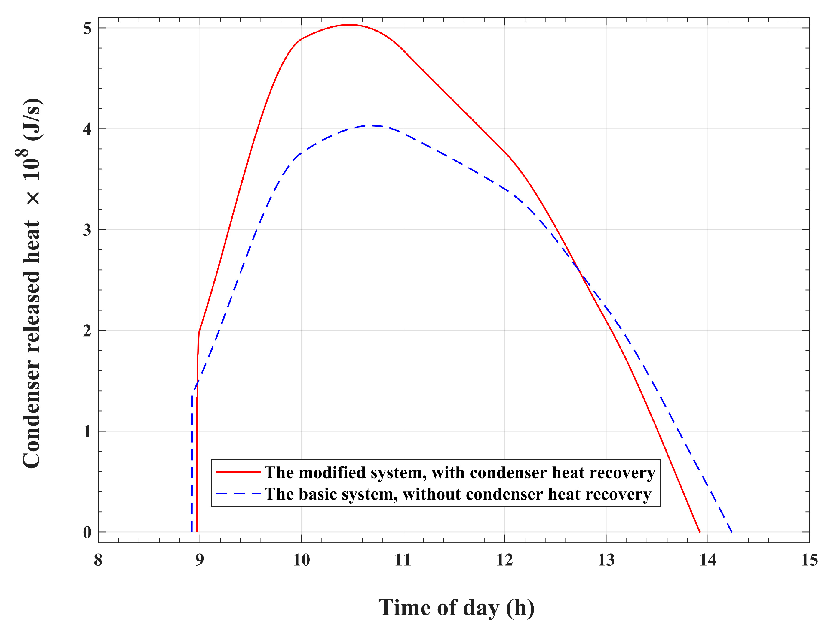
Figure 8 shows the temporal changes in refrigerant condensation heat,
, which is released inside the condenser tubes by the vapor that desorbs from the bed. One plotted profile represents the temporal variation in the released and recycled condensation heat for the modified system, and the other plotted profile represents the temporal variation in the released condensation heat for the basic system, which is dumped into the atmosphere.
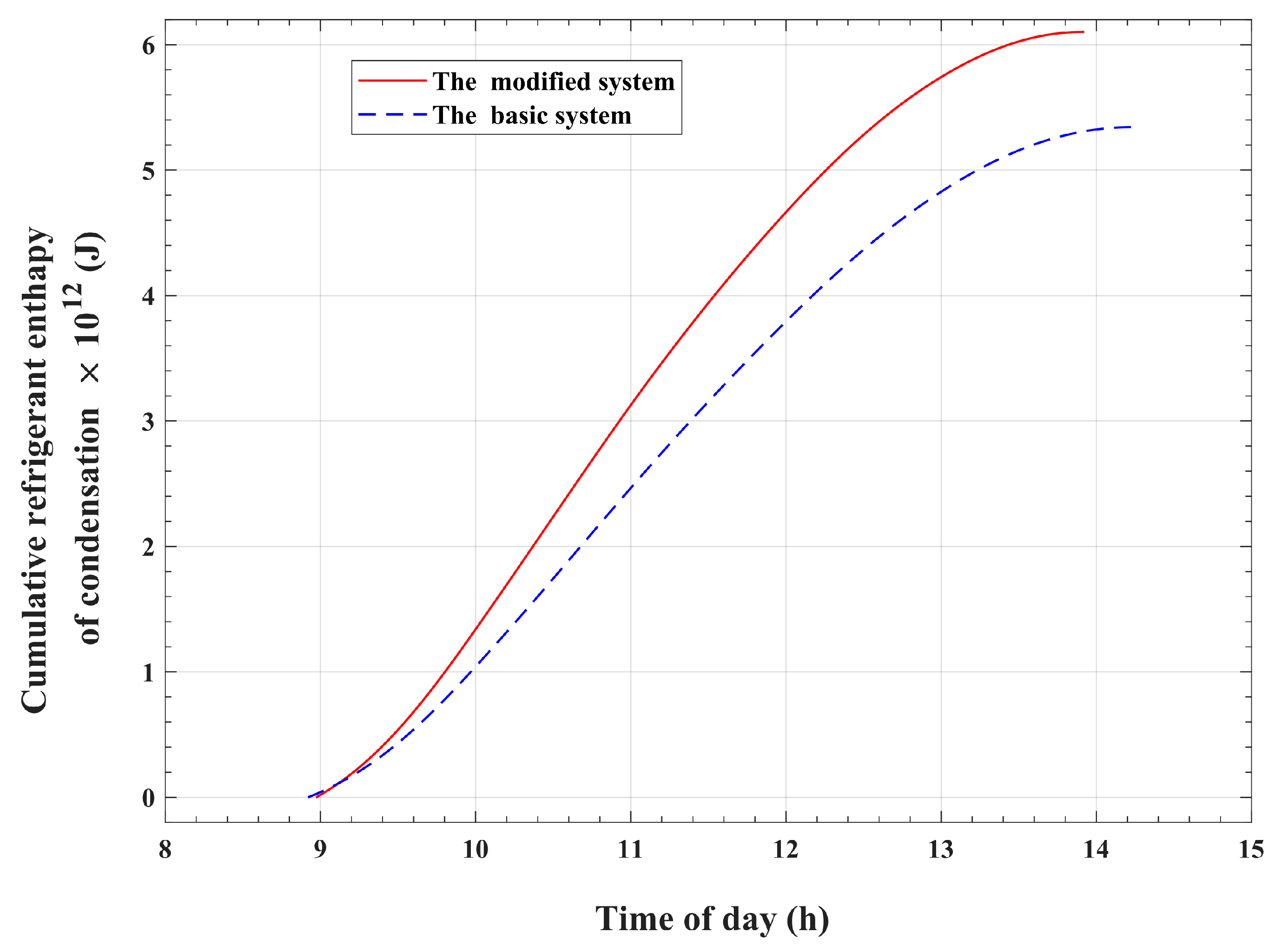
Figure 9 plots the corresponding time-integrated released condensation thermal energy at the condenser. As illustrated in
Figure 8 and
Figure 9, the evidence that the released heat of condensation is affected by the process of condenser heat recapture is pronounced. The differences between the condenser-released heat with and without heat recovery are obvious, and they deserve thorough investigation. For the modified system, with condensation heat reutilizing, the desorption–condensation operation ends earlier, at 13:55, compared with the corresponding operation in the basic system, which takes longer and ends at 14:14. Moreover, higher rates of released enthalpy of condensation are noticed for the modified system, which reuses condenser heat. The major reason behind these differences is that the recycled refrigerant enthalpy of condensation acts as an additional thermal energy source that assists the absorbed solar radiation and accelerates the process of refrigerant desorption from the adsorption reactor. Furthermore, this extra heat source produces a further increase in the adsorption pair temperature. Consequently, in the case of the heat reuse system, a larger amount of refrigerant vapor is freed from the adsorption bed and transfers to the condenser tubes compared with the system without heat recirculation. Hence, this larger amount of desorbed refrigerant vapor explains why the released condenser heat is higher for the modified system compared with the corresponding heat for the basic system.
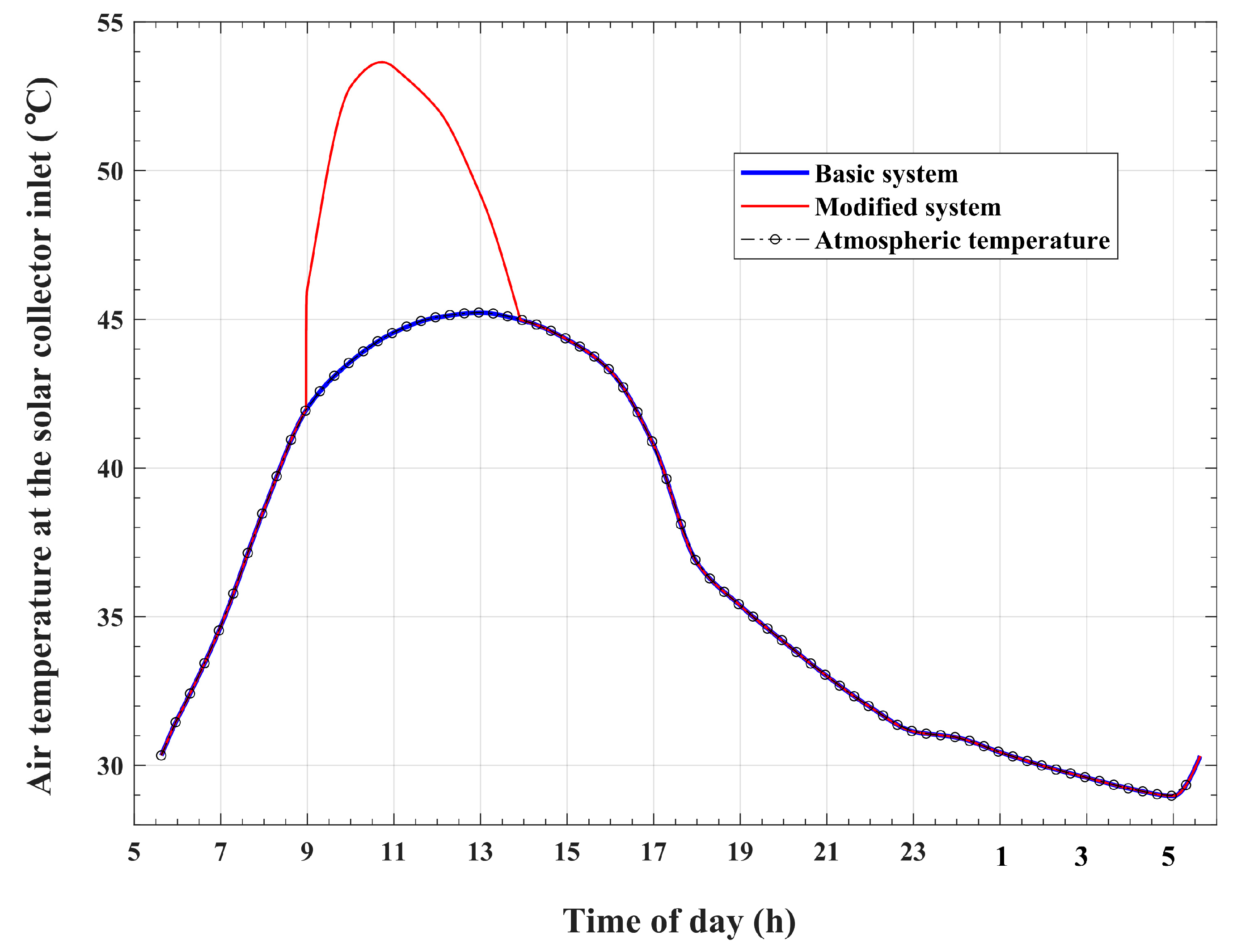
The influence of condenser heat reuse on the airflow total temperature at the solar collector inlet is illustrated in
Figure 10. It is apparent that the air total temperature at the solar collector inlet,
, has a time-varying profile that coincides with the atmospheric temperature variation pattern for the basic system. However, a temperature rise above that of the atmosphere is observed during the desorption and condensation periods in the case of the modified system. The air temperature profile shows a temporal variation pattern that matches the variation profile of the recycled condensation heat, as given in
Figure 8. The peak of the inlet air total temperature is approximately 53.6 °C and is noticed at 10:43 in the day. This increase in air total temperature at the solar collector inlet for the modified system compared with the basic system is a result of the recycled condenser thermal energy.
Table 4 compares the values of the thermal energy components obtained for various thermodynamic processes of the adsorption cooling module for the introduced enhanced system and the original basic system. It is found that the total amount of thermal energy absorbed by the adsorption reactor during the preheating and desorption processes,
, is
for the modified system, compared with a value of
for the basic system. The time-accumulated thermal energy that is released by the refrigerant condensation process,
, is found to be
for the enhanced system, which is larger compared with the corresponding amount of
for the basic reference system. Therefore, the system without condenser heat recirculation wastes an amount of thermal energy that equals approximately 68.2% of the total activation thermal energy that is required to release the refrigerant vapor from the reactor. However, the present improved system, with condenser heat recycling, recirculates and reuses this amount of thermal energy, which is found to be 77.9% of the total thermal energy required to release refrigerant vapor from the reactor of the basic reference system. Furthermore, an increase of approximately 14.2% in the enthalpy of condensation is obtained by the present improved system with condenser heat reuse compared with the unmodified basic system. Consequently, the modified system presents a double-effect enhancement. This means that the process of condenser heat retrieval not only allows for the reuse of the basic system’s wasted condensation enthalpy but also causes an augmentation in the recycled condensation thermal energy. The thermal energy ejected by the adsorption reactor during the depressurization and adsorption processes,
, is transferred to the air stream under the solar collector. This thermal energy causes a temperature increase in the solar collector air, which, as a result, produces an increase in the chimney updraft and pressure potential. It can be seen from the data in
Table 4 that the adsorption reactor releases a larger amount of thermal energy,
, in the scenario of condensation enthalpy reutilization compared with the corresponding amount of
in the basic system scenario with condensation heat wasting. In other words, the enhanced and modified system, which allows condensation heat to be recirculated, produces approximately 10.7% excess thermal energy, which is dissipated by the adsorption reactor during the depressurization and adsorption operations, compared with the basic system. It can also be noticed in
Table 4 that the cooling effect for the system with condenser heat recirculation is about 14.2% larger than that for the unmodified original system, which ejects the condensation thermal energy into the environment.
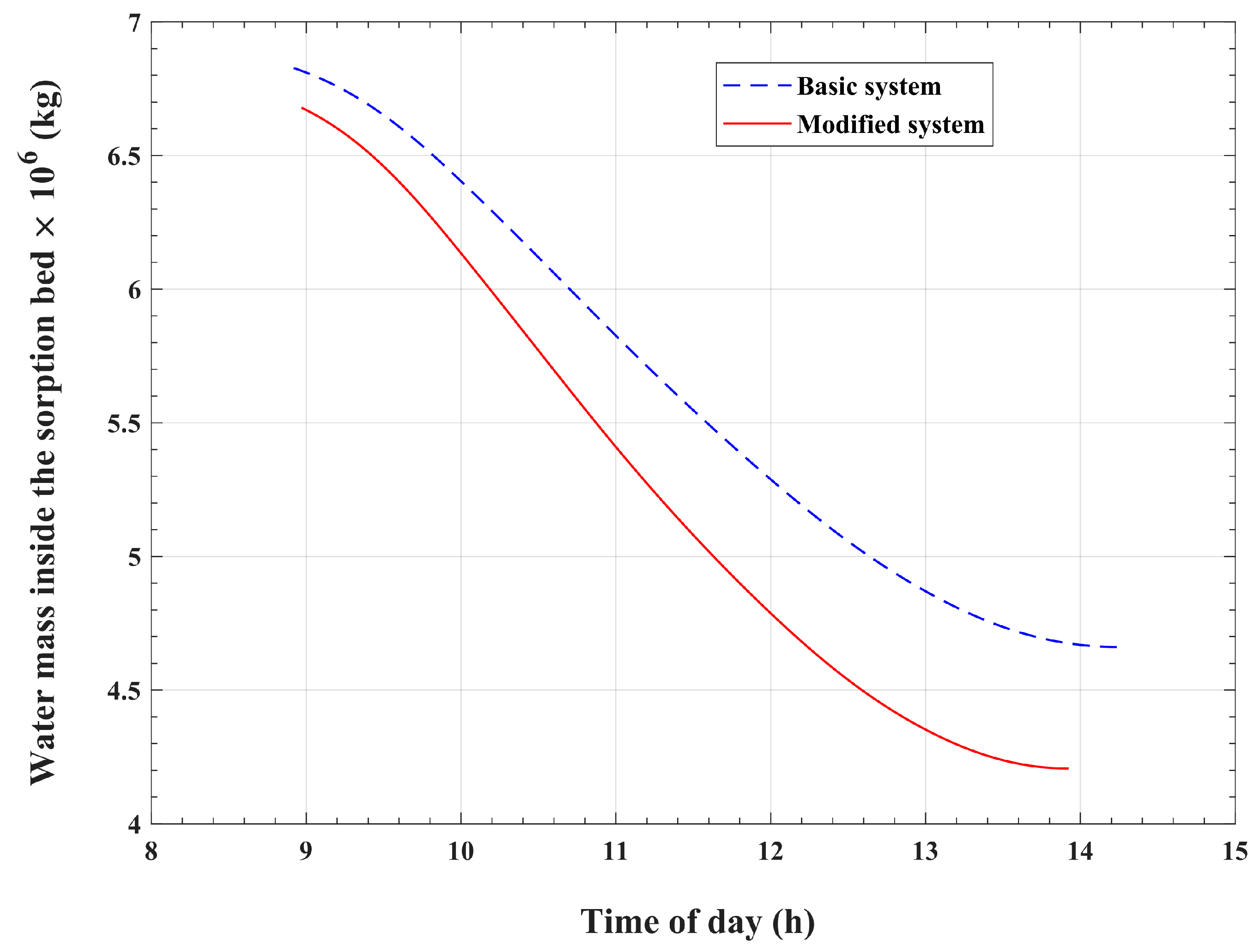
The changes in refrigerant mass within the adsorption bed with respect to the time of day during the desorption and condensation processes are shown in
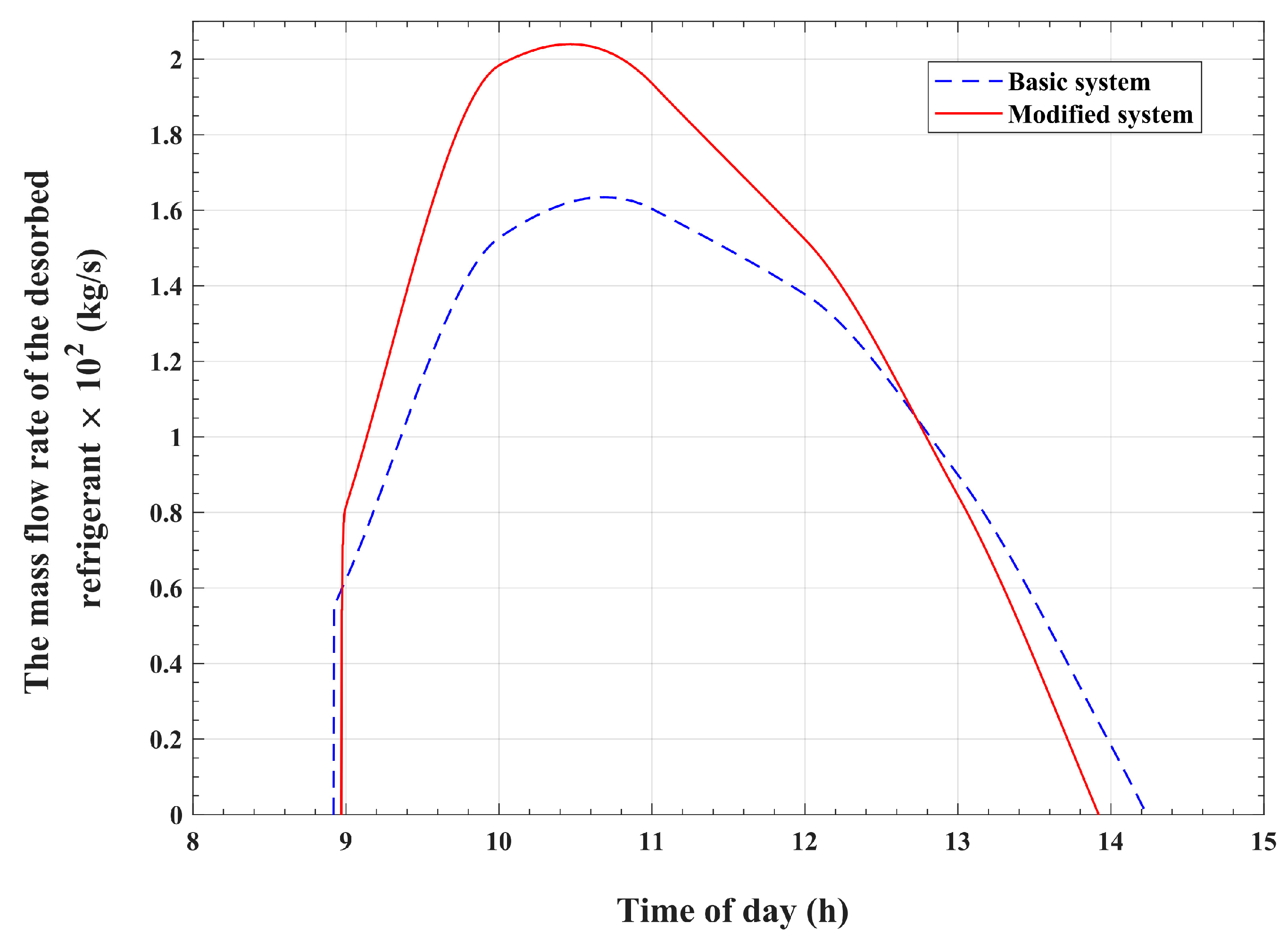
Figure 11. The variations in the desorbed refrigerant mass flow rate with the time of day are plotted in
Figure 12. These figures compare the refrigerant mass profile of the present improved system and the corresponding profile of the original reference system. The adsorption reactor begins the desorption process with initial refrigerant mass contents of approximately
and
for the modified system and the reference basic system, respectively. The refrigerant mass inside the bed of the modified system is nearly 2.2% less than the same mass for the unmodified basic system. This slight difference is due to the slightly higher initial bed temperature in the modified system, which is precisely 35.42 °C, compared with that of the basic system, which is approximately 35.0 °C. As illustrated in
Figure 11, both compared systems show decreasing profiles of bed refrigerant mass content during the isobaric desorption process. However, the bed refrigerant mass content decreasing rate is higher for the system that recirculates the condensation heat compared with the other reference system. As is apparent in
Figure 12, both the modified and the basic systems attain comparable temporal variation behavior for the desorbed refrigerant mass flow rate. At the start of the desorption process, both profiles show an abrupt jump from a zero mass flow rate to a starting value of 80 kg/s for the modified system and 55 kg/s for the basic system. Thereafter, the refrigerant mass flow rate shows a continuous increasing profile before reaching a peak value, after which it starts to decline until the desorption process ends. This behavior of desorbed mass flow rates results in comparable profiles and corresponding peaks for the condenser-released heat, as is evident in
Figure 8. As can be noticed in
Figure 12, the peak of the desorbed refrigerant mass flow rate from the bed takes place at 10:28, with a rate of 204 kg/s for the modified version of the system. This corresponds to a peak with a rate of 163.5 kg/s that takes place at 10:41 for the basic reference system. The higher values of desorbed mass of refrigerant vapor in the modified system can be explained by the effect of reused condenser thermal energy, which causes higher levels of bed temperature compared with the basic reference system. At the end of the desorption process, the mass of water inside the adsorption bed is found to be approximately
for the introduced modified system compared with approximately
for the unmodified basic system. In other words, the adsorption reactor releases
of refrigerant vapor to the condenser in the present enhanced system, which reuses condenser heat, compared with
in the system conventional version, which dissipates condenser heat into the environment. Therefore, an approximately 14.2% increase in desorbed refrigerant mass from the sorption reactor can be achieved with the introduced modification, whereby the system recycles the refrigerant vapor enthalpy of condensation. Moreover, this increase in desorbed mass causes a corresponding, equal increase in recycled condensation heat, as previously discussed in relation to the data provided in
Table 4.
The changes in refrigerant mass within the adsorption bed with time during the isobaric adsorption and cold production processes are illustrated in
Figure 13 for the basic and modified systems. The results show that the bed refrigerant mass increases from
to
in the modified system, which corresponds to an increase from
to
in the basic system. Consequently, the effective amount of refrigerant vapor that circulates inside the cooling module, between the evaporator and the condenser, and produces the cooling effect is approximately
for the modified system, which is larger compared with the corresponding amount of approximately
for the basic reference system. This represents an increase of approximately 14.2% in the effective refrigerant mass in the present improved system, which recycles condenser heat, compared with the corresponding mass in the basic system, which wastes the refrigerant heat of condensation. Moreover, the ratio between the refrigerant effective mass and the initial refrigerant mass content of the reactor is found to be 37% for the modified system, which is higher compared with the corresponding value of 32% for the basic system. This means that the present modified system utilizes the refrigerant content of the adsorption reactor in a more efficient way compared with the basic system.
Figure 14 compares the refrigerant-adsorbed mass flow rate for the present enhanced system with that of the reference basic system. It can be noticed from the plots in
Figure 14 that the modified system attains pronouncedly higher values of mass flow rates at all times compared with the corresponding values for the reference basic system. Therefore, as demonstrated in
Figure 15, the corresponding cooling effect attains an increased value of
for the modified system over a corresponding value of
for the unmodified reference system. Therefore, a 14.2% increase in the evaporator cooling effect can be obtained with the modified system compared with the basic system. The coefficient of performance (COP) is one of the performance indicators of cooling systems. The COP is defined as the ratio between the cooling effect at the evaporator and the total heat that is required to generate the refrigerant from the adsorption bed during the pressurization and desorption processes. It is found that the COP for the presented enhanced system is approximately 0.67, which is higher compared with the COP value of 0.64 for the basic system.
The changes in the temperature of the refrigerant inside the adsorption reactor with the time of day for the present improved system as well as the original basic system are demonstrated in
Figure 16. As is apparent in this figure, both systems generally exhibit similar temperature behavior during the operating cycle. Nonetheless, the adsorption reactor of the system with condenser heat recirculation acquires a higher temperature increasing trend during the desorption and adsorption processes compared with the basic system temperature profile. During the desorption–condensation operations, the adsorption bed attains a maximum temperature of approximately 77.6 °C at 13:55 for the modified system, which is 1.9 °C higher when compared with about 75.7 °C at 14:14 for the original basic system. It is obvious that this 1.9 °C difference in temperature is mainly due to the impact of the extracted and reused refrigerant vapor condensation enthalpy. Furthermore, the plotted temperature profile of the modified system during the adsorption process generally indicates higher temperature values compared with the original basic system. This trend can be explained by the effect of the larger amount of adsorption bed-released sorption heat, which corresponds to a larger amount of adsorbed refrigerant vapor compared with the basic system.
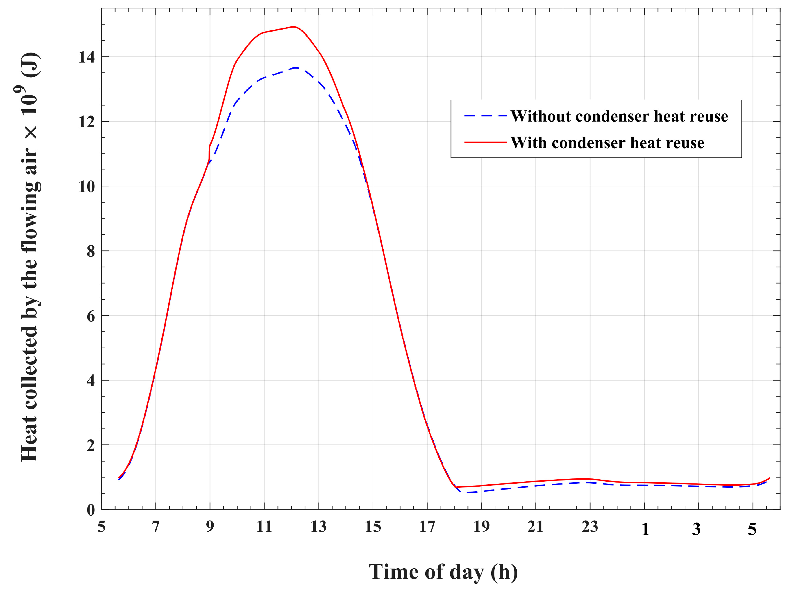
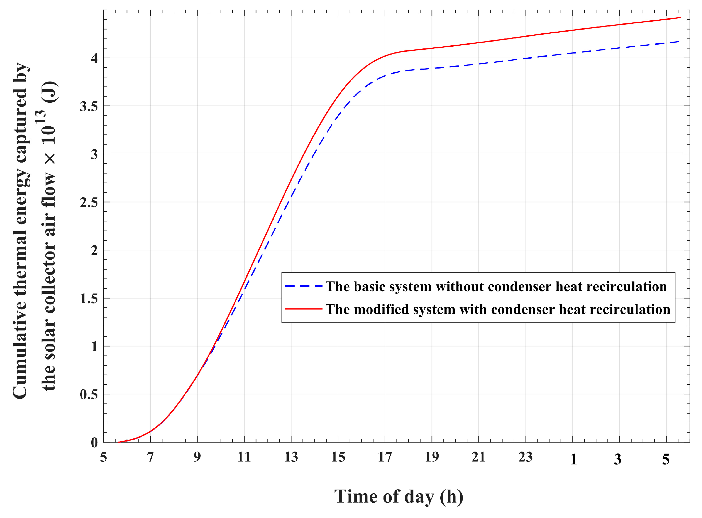
Figure 17 compares the temporal changes in the thermal energy that is carried by the airflow under the solar collector roof in the modified system and the basic system. Moreover, the time accumulation of this thermal energy is plotted in
Figure 18 for the presented system and the basic system. It is apparent that the modified system obtains higher values of the amount of thermal energy carried by the collector airflow compared with the basic system. By the end of the operating cycle, the airflow of the modified system is found to gain about
thermal energy compared with the corresponding amount of about
of the basic system. This represents a value of 5.95% increase compared with the thermal energy gained by the basic system. As a result, the airflow under the transparent roof of the solar collector is expected to attain higher temperatures in the case of the modified system compared with the case of the basic system. This influence is obvious in
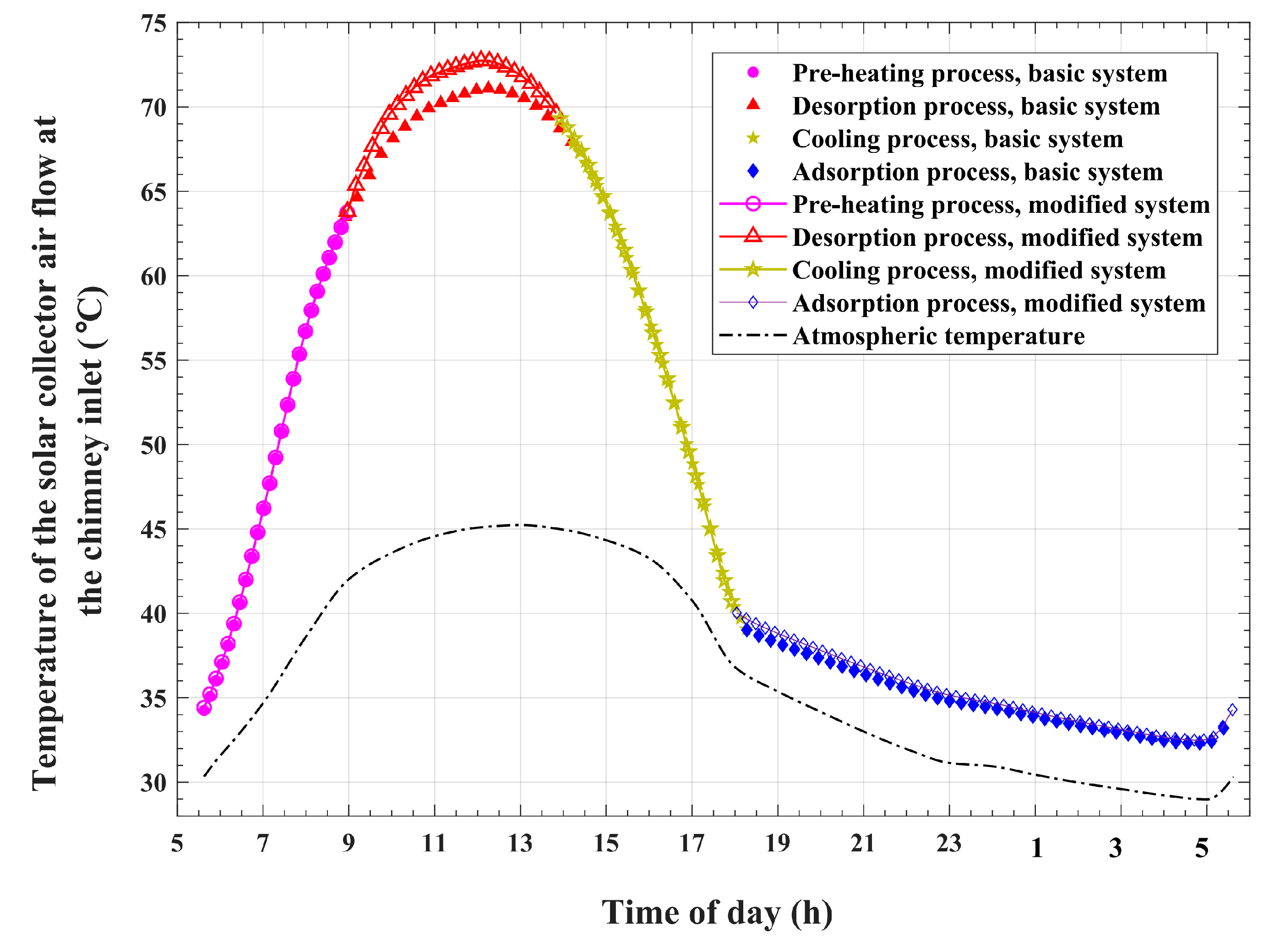
Figure 19, which compares the temporal variations in airflow temperatures at the exit of the solar collector and inlet of the chimney for the modified system and those for the basic system. The plots show remarkable higher temperatures at the chimney inlet for the modified system compared with the reference basic system during the desorption and condensation operations. This noticeable temperature difference is a direct result of the recirculation and reutilization of condensation thermal energy. Furthermore, a slight increase in the chimney inlet airflow temperatures is seen during the adsorption and cold production processes. This increase is directly caused by the larger adsorbed refrigerant amount and the corresponding increased heat of adsorption, as explained in
Figure 13, for the modified system compared with the basic system, which is indirectly related to condenser heat recycling.
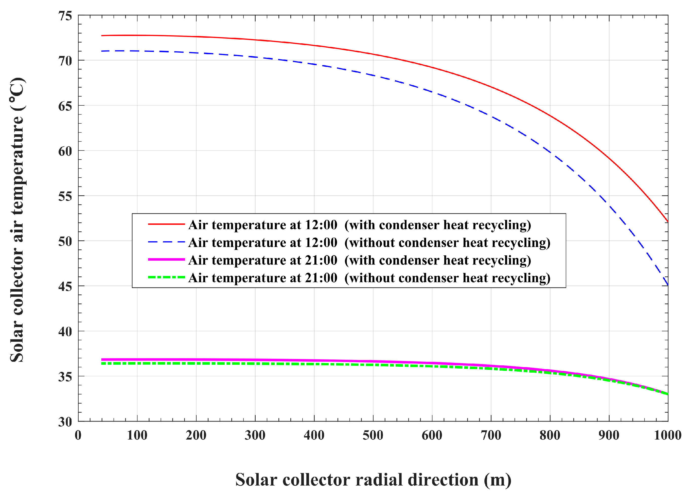
In order to meticulously scrutinize the spatial variations in the airflow parameters inside the solar collector from its inlet to its exit, two instantaneous snapshots are taken at two arbitrary time points. One time point is taken to be within the desorption and condensation period, at 12:00, whereas the other time point is taken to be within the adsorption and cold generation period, at 21:00. The variations in the solar collector airflow temperatures in the radial direction at the 12:00 and 21:00 times of day are plotted in
Figure 20 for the modified and basic systems. Generally, an increasing trend is pronounced for all the plotted variations in air temperature in the inward radial direction. This increasing trend in air temperature can be justified by the continuous thermal energy transferred from the solar absorber plate to the air stream while the air moves from the solar collector inlet to its exit in the inward radial direction. Nonetheless, the gradients in air temperature are higher at the solar collector outer radii compared with these gradients in temperature at positions at inner radii, and this applies to all the temperature profiles, as illustrated in
Figure 20. In other words, the airflow temperature gradients decrease in the inward direction of the solar collector. This is because of the decrease in the amount of heat transferred from the solar-absorbing plate to the airflow due to the decrease in the plate surface area in the inward radial direction. Furthermore, the behavior of airflow temperature gradients varies depending on the system as well as the time of day.
At 12:00, both the modified and the basic systems undergo desorption and condensation operations. In the meantime, the absorber plate collects solar radiation and transfers heat to the airflow. For the basic system, which dissipates condensation heat into the environment, the heat transferred from the absorber plate is the only source that causes an increase in air temperature. As shown in
Figure 20, the airflow temperature increases from 45 °C, which equals the ambient temperature at 12:00, at the collector inlet to 71 °C at its exit in the basic system at 12:00, whereas the modified system acquires an excess amount of transferred heat compared with the heat that is gained by the basic system. This excess heat is obtained through the process of condenser heat recirculation and reuse. The influence of condenser heat recycling in the case of the modified system is pronounced at the inlet boundary of the solar collector. A higher value of inlet air temperature of 52 °C is obtained in the modified system because of condenser heat reutilization compared with 45 °C in the basic system. At the exit of the collector, the modified system attains an airflow temperature of 72.7 °C. As a result, the modified system gains a 1.7 °C rise in solar collector temperature compared with the basic system due to condenser heat recirculation. It can also be noticed that for the modified system, the airflow temperature increases by two times. The first increase, which is obtained across the condenser, is of 7 °C, and the second increase, which is gained across the solar collector, is of 20.7 °C. On the other hand, the basic system gains an increase in airflow temperature across the solar collector of 26 °C, compared with 20.7 °C for the modified system. This is because a larger amount of refrigerant is released by the bed, and consequently, a larger amount of heat is consumed by the reactor in the case of the modified system compared with the basic system, as previously discussed in relation to the data given in
Table 4.
With regard to the airflow temperature spatial variations at 21:00, during the adsorption and cold generation operations, the temperature gradients are noticed to be lower than the corresponding gradients at 12:00 for the two systems. The only driving source of heat for both the modified and basic systems is the corresponding adsorption bed-released heat, which is larger in the case of the modified system compared with the basic system, as previously discussed with the data given in
Table 4. This results in a slight increase in the airflow temperature of the modified system compared with the basic system. Since there is no recycled condensation heat during the adsorption process, the airflow enters the solar collector at the ambient temperature of 33 °C in both system cases. The air stream temperatures at the exit of the collector are found to be 36.8 °C for the modified system and 36.4 °C for the basic system. This slight increase, of about 0.4 °C, is due to the larger amount of adsorbed refrigerant in the case of the modified system, which releases a larger amount of sorption heat into the air stream compared with the basic system.
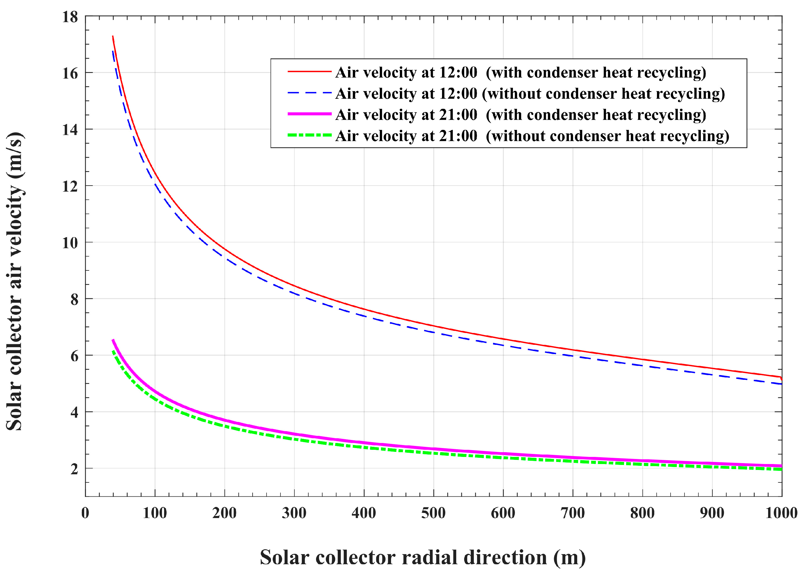
Figure 21 compares the spatial variations in the solar collector airflow velocities in the radial direction for the modified system with the corresponding airflow velocities in the basic reference system at the 12:00 and 21:00 times of day. As can be noticed in the figure, the plotted velocities show continuous increases in values with increasing gradients in the inward direction. These increased velocity values and increased velocity gradients are mainly related to two reasons. The first reason is the influence of the flow passage, which converts in the direction towards the center of the solar collector. The second reason is the continuous increase in airflow temperature in the inward radial direction, as discussed for the results in
Figure 20. This increase in airflow temperature causes a corresponding decrease in air density. Therefore, to conserve the mass flow rate, the air volume flow rate and the air velocity should increase in the inward radial direction. As can be seen from
Figure 21, the presented modified system obtains slightly larger values of airflow velocities at all radii as well as at all times compared with the basic system.
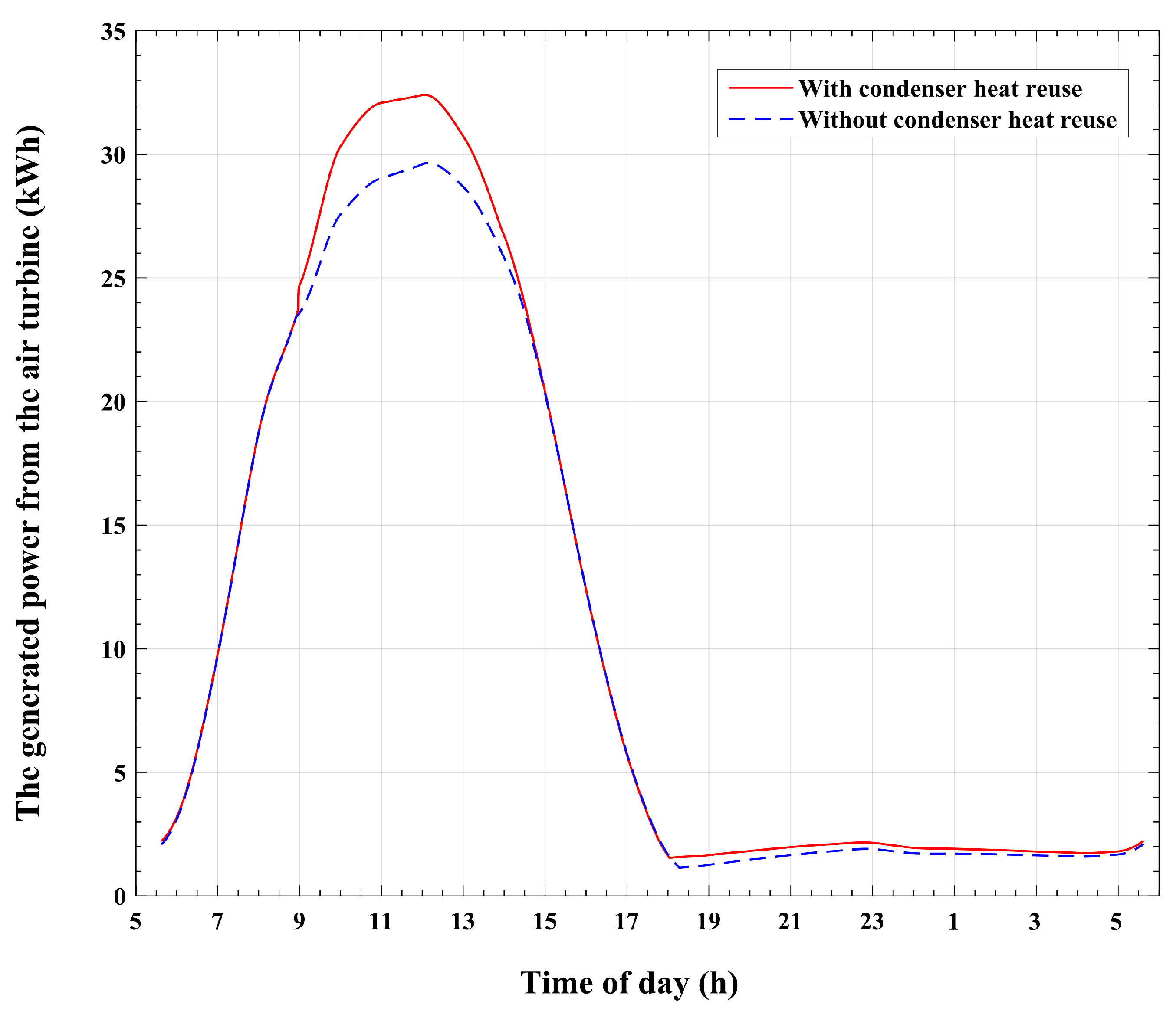
The influence of condenser heat recycling on the air turbine-produced power is illustrated in
Figure 22. This figure compares the turbine-generated power of the modified system with that of the basic system at all times during the cycle of operation. It can be noticed that the power curve of the modified system attains higher values compared with the basic system during the desorption and condensation operations. Furthermore, a slight increase in air turbine output power is observed for the modified system compared with the basic system during the adsorption process. It is also found that the total power generated by the turbine reaches a value of 96.915 MWh for the presented system, compared with power generation of about 91.47 MWh for the reference system. Therefore, an approximately 5.445 MWh increase in turbine power is obtained with the modified system compared with the basic reference system. This means that a 5.95% increase in output power can be achieved through the recirculation and reutilization of the heat of condensation. Most of this increase in turbine power, approximately 78.05%, is obtained during the desorption and condensation operations, and 18.33% of this increase is obtained during the adsorption and cold production operations. It is also found that during the pressurization and depressurization processes, there are no observed significant increases in the turbine-generated power in the modified system compared with the basic system. Furthermore, the increase in turbine power corresponds to an improvement in solar-to-electricity efficiency. Solar-to-electricity efficiency is defined as the percentage of the turbine that produces electric energy out of the total incident solar thermal energy. The modified system attains a solar-to-electricity efficiency rate of about 0.424%, compared with the corresponding value of 0.4% for the basic system. This represents an increase of 6% in solar-to-electricity efficiency with the modified system compared with the basic system.
7. Conclusions
Solar updraft tower power plants promote the utilization of sustainable energy sources owing to their cost effectiveness, minimal maintenance requirements, and environmentally friendly nature. Nevertheless, despite extensive endeavors to enhance the design of these plants, their energy conversion efficiency and capacity for power generation continue to be constrained. Scholars have conducted investigations into alterations in plant geometry and hybridization techniques in order to enhance energy conversion efficiency. A solar chimney power plant integrated with an adsorption cooling system for power and cold cogeneration was first introduced in a previous work [
3]. This hybrid system was an integral part of two modules. The first module represents a solar chimney power plant. The second module is a solar-driven adsorption cold-generating system. The adsorption bed is placed under the transparent roof of the solar collector in order to recycle the heat released by the adsorption bed during bed depressurization and adsorption operations. It was proven, in this previous work, that reusing the heat released by the adsorption bed enhances the system’s utilization of solar energy and increases the turbine output power by a value of 3.22%. In addition, solar-to-electricity efficiency was found to be 0.4%.
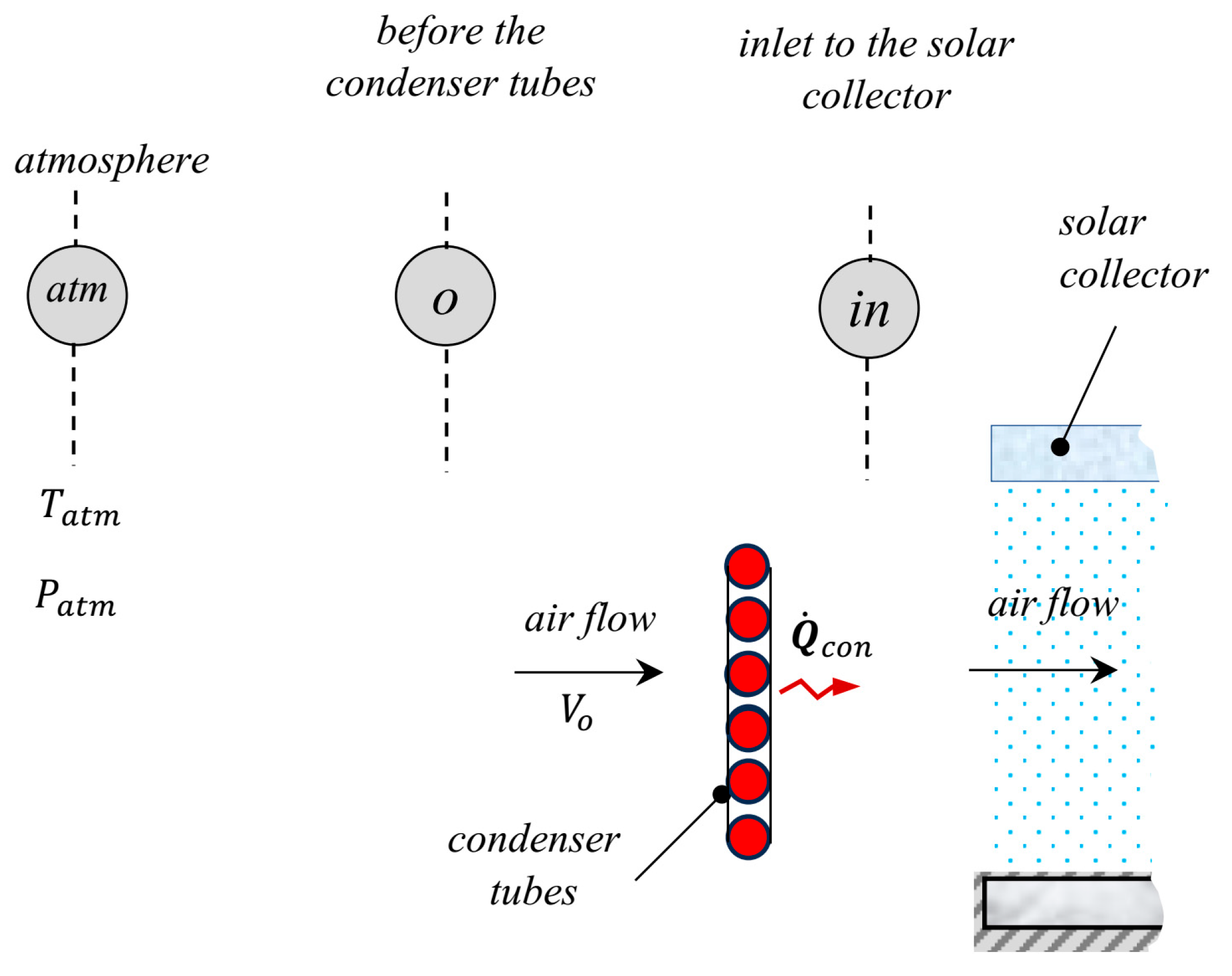
In the present paper, an additional modification to the preceding basic system’s arrangement and operation is introduced. The reason for this modification is to attain an additional performance improvement over the basic reference system and to optimize the consumption of solar energy. The modification is performed by placing the condenser tubes in a cross-flow with the inlet air stream. These tubes have a helical profile and are fixed along the circumference of the solar collector entrance. This modified configuration permits the capture of the heat of condensation by the solar collector airflow. This operation takes place during the refrigerant desorption and condensation processes. The recovered condenser heat causes an increase in the temperature of the solar collector inlet airflow. This causes a temperature rise in the airflow exit of the collector and an increase in the power generated by the air turbine. Another benefit of the introduced system is that it does not require a water source for condenser cooling, making it particularly suitable for desert climates. The significance of this characteristic is anticipated to amplify in the near future due to the projected escalation of desertification throughout extensive regions as a consequence of climate change. Furthermore, the position of the condenser tubes at the solar collector entrance provides enhanced cooling for the refrigerant vapor due to the forced convection effect, which is induced by the airflow entering the solar collector due to the chimney updraft effect. This method provides a rapid cooling and condensation process for the refrigerant vapor compared with the conventional condenser, which is cooled through natural convection.
The configuration and operation of the present modified system are introduced. A dynamic mathematical model for the combined solar collector and the adsorption cooling modules is established to simulate the hybrid system’s operation and evaluate its parameters. The adsorption pair that is used in this work is silica gel and water. The climatic data used in the simulation represent the hourly solar radiation, the hourly atmospheric temperature, and the hourly wind speed.
The process of condenser heat regaining not only allows for the reuse of the basic system’s wasted condensation enthalpy but also causes an augmentation in the recycled condensation thermal energy. It is found that the modified system recirculates and reuses an amount of thermal energy that is about 77.9% of the total thermal energy required to release refrigerant vapor from the reactor of the basic reference system. Moreover, an increase of approximately 14.2% in condenser-released heat is obtained through condenser heat recycling. Furthermore, the modified system produces about 10.7% excess thermal energy, which is dissipated by the adsorption reactor during the depressurization and adsorption operations, compared with the basic system. It is also found that the cooling effect for the system with condenser heat recirculation is approximately 14.2% larger than that of the unmodified basic system, which ejects the condensation thermal energy into the environment. Moreover, the ratio between the refrigerant effective mass and the initial refrigerant mass content of the reactor is found to reach a value of 37% for the modified system, which is higher compared with the corresponding value of 32% for the basic system. Furthermore, a 5.95% increase in output power can be achieved through the reutilization of the heat of condensation. In addition, the modified system attains a 6% increase in solar-to-electricity efficiency compared with the basic system. The findings suggest that the modified system, which recycles condenser heat, provides noticeable enhanced performance compared with the basic system.
Although the modified system provides more power than the basic system after sunset, the amount of this power is lower after sunset than it is during the day. Hence, this causes a restriction on the system’s operation and reduces its dependency on the system’s produced power after sunset. Therefore, it is necessary to conduct more research in order to get round this restriction. Future research will examine the system’s sensitivity to parameter variation in order to identify the system’s optimal design parameters and operating constraints. Additionally, we will look into integrating the suggested technology with additional uses, like desalination and/or thermal energy storage.


