
Application of Auxetic Tubular Structure in Flow Control of the Throttle Valve


Abstract
:1. Introduction
2. Analytical and Numerical Models
3. Experiment
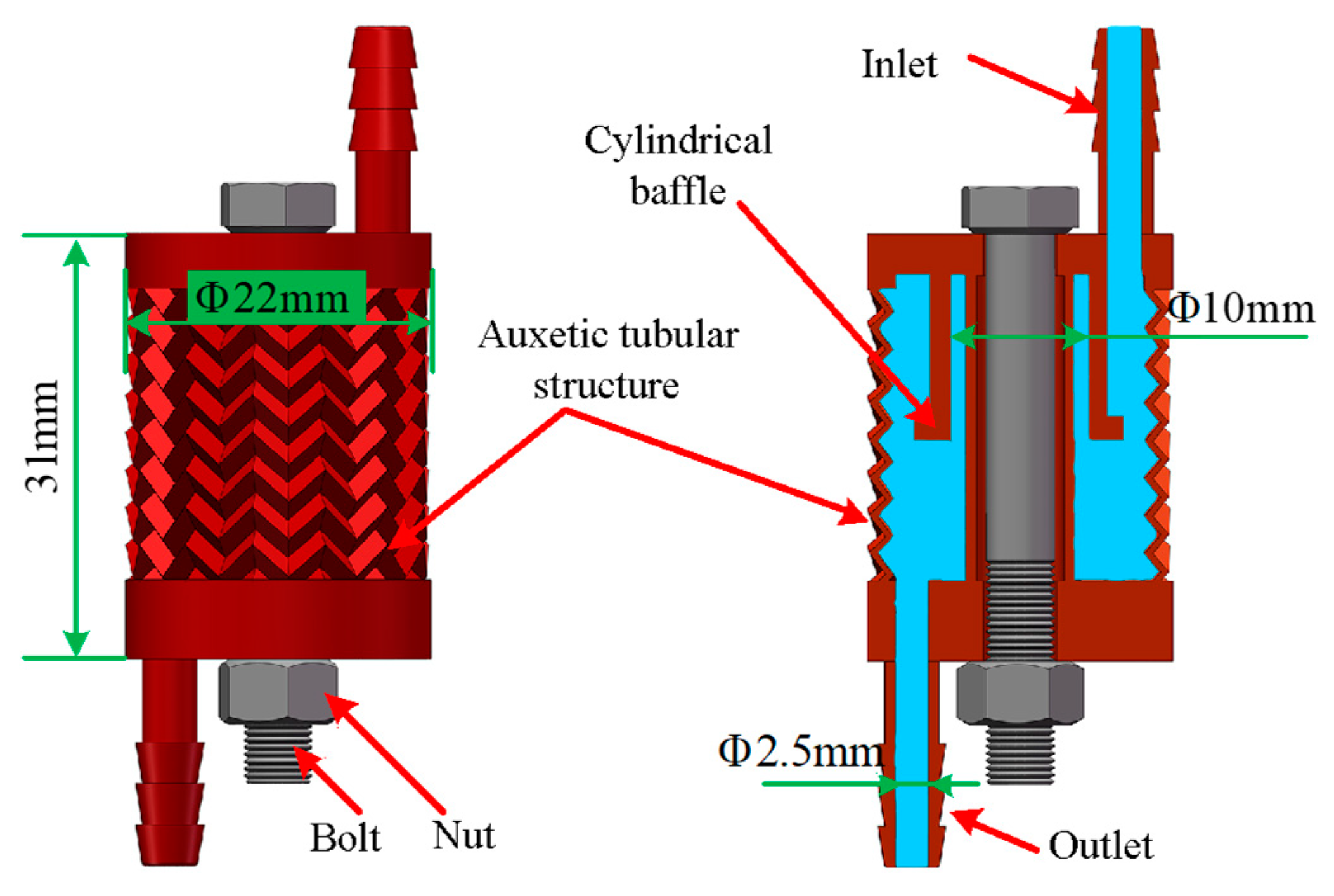
3.1. Geometry of the Flow Control Device
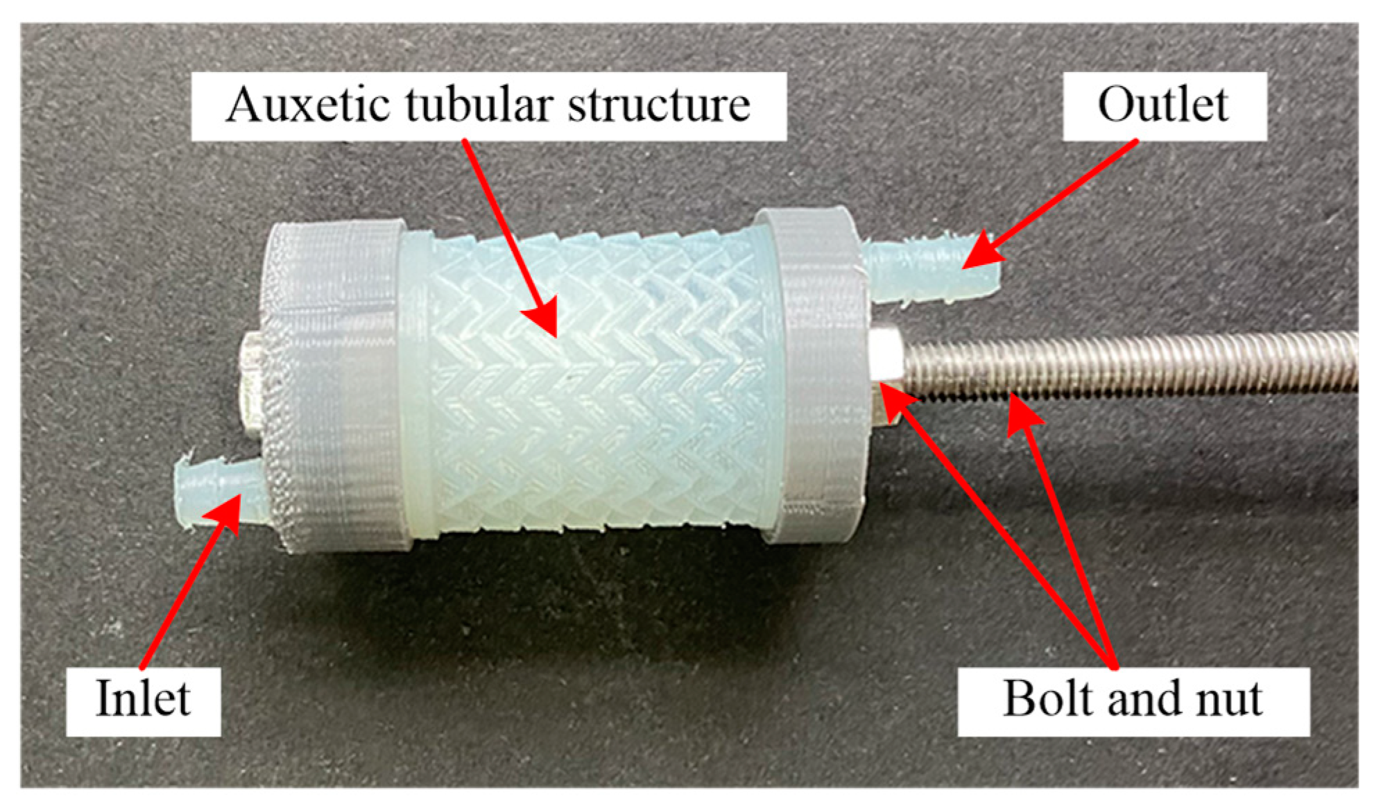
3.2. Preparation of the Flow Control Device
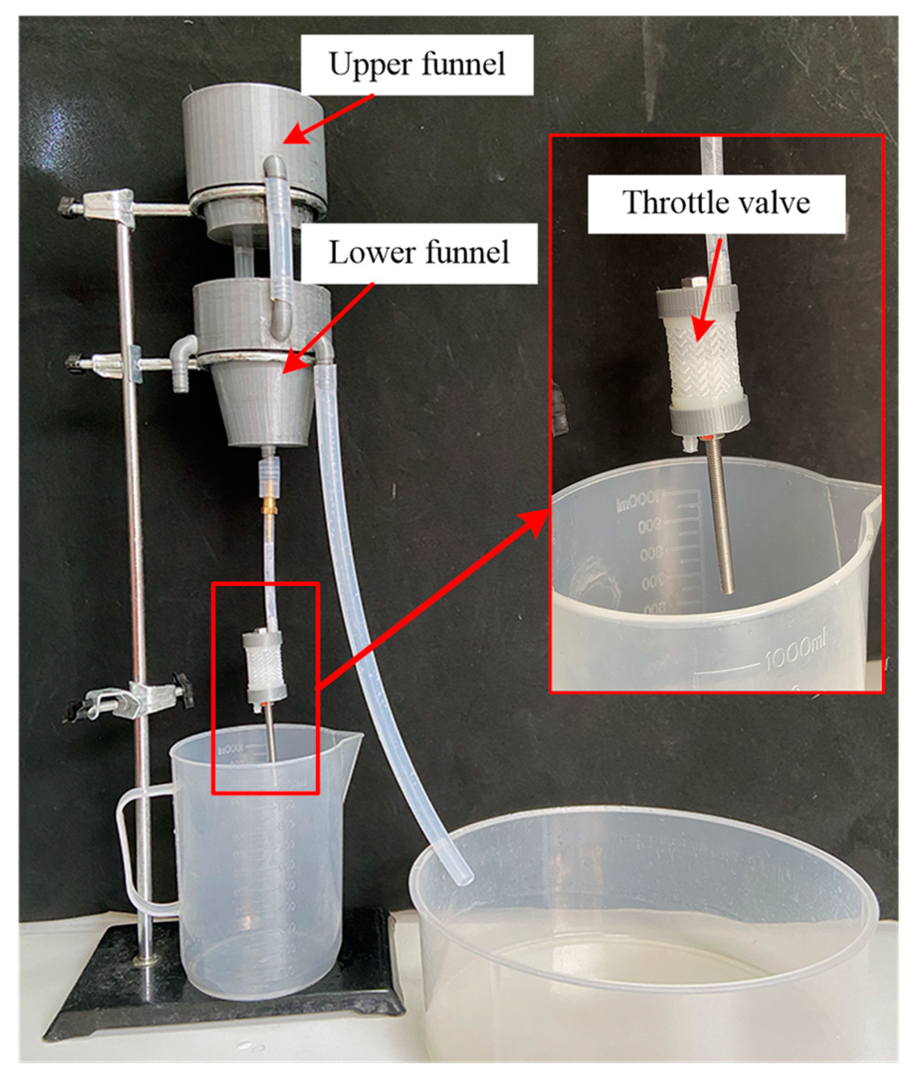
3.3. Experimental Set-Up
4. Results and Discussion
5. Conclusions
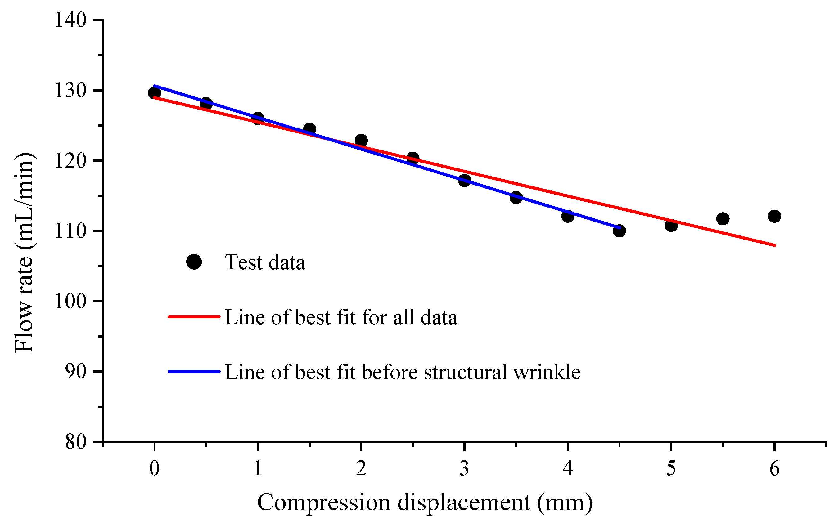
- The proposed method exhibits good linearity, which means that the variation in flow rate can be predicted and controlled under different compression displacements. This linear relationship makes the method easier to calibrate and adjust in practical engineering applications.
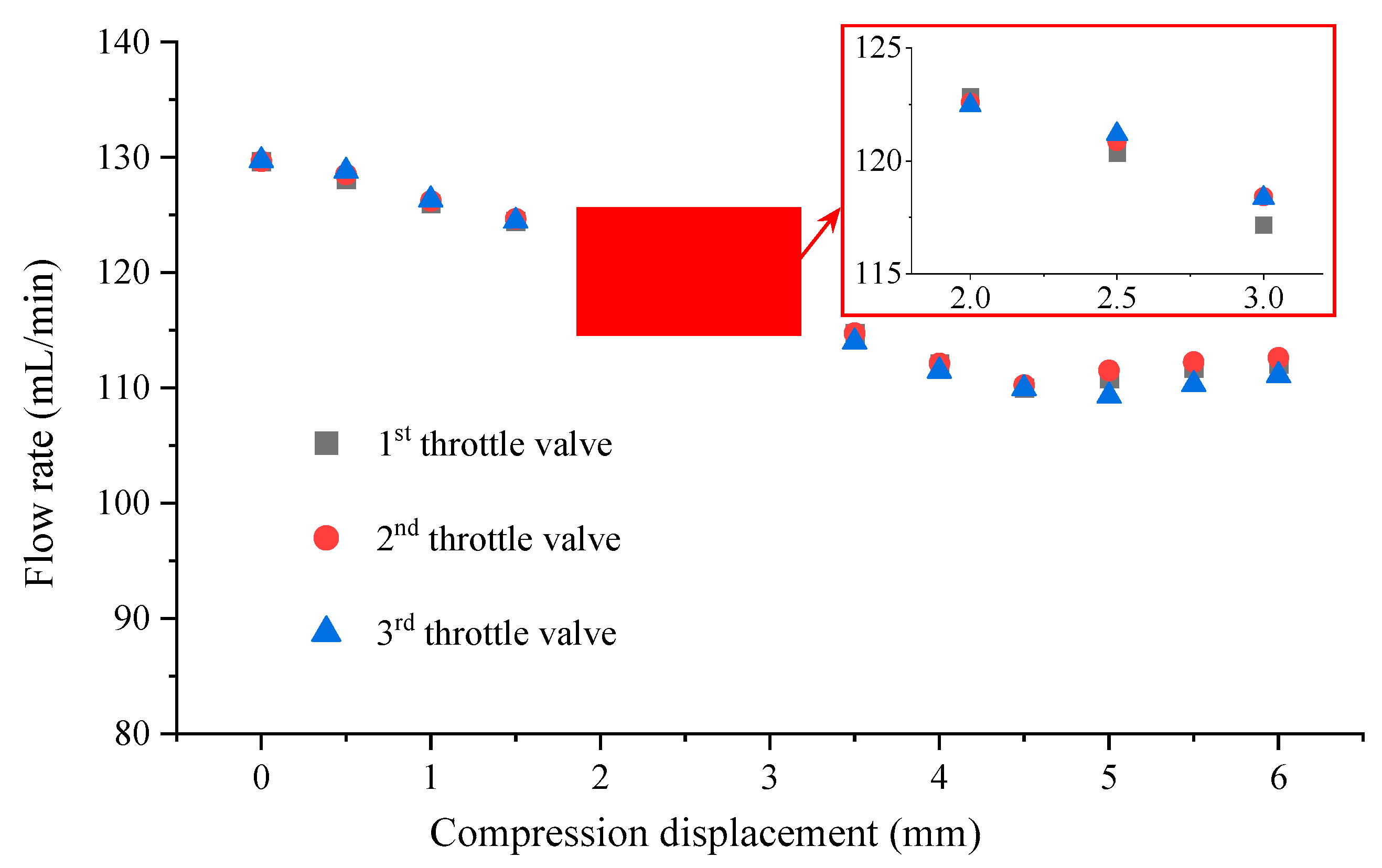
- The proposed method demonstrates good repeatability, indicating that it can maintain its performance over long-term use, thereby enhancing its practicality and reliability.
- Although the current method has a limited range of flow-rate variation, optimization of the design of the auxetic tubular structure, such as by changing the shape and size of the cylindrical baffle or the dimensions of structures, can expand the controllable range of the flow rate. This enhancement would increase the method’s applicability and flexibility.
Author Contributions
Funding
Data Availability Statement
Conflicts of Interest
References
- Lund, H.; Salgi, G. The role of compressed air energy storage (CAES) in future sustainable energy systems. Energy Convers. Manag. 2009, 50, 1172–1179. [Google Scholar] [CrossRef]
- Zhang, S.; Wang, H.; Li, R.; Li, C.; Hou, F.; Ben, Y. Thermodynamic analysis of cavern and throttle valve in large-scale compressed air energy storage system. Energy Convers. Manag. 2019, 183, 721–731. [Google Scholar] [CrossRef]
- Zhang, W.; Liu, Y.; Li, S.; He, T.; Liu, J. Experimental and simulative study on throttle valve function in the process of wave energy conversion. Adv. Mech. Eng. 2017, 9, 1–10. [Google Scholar] [CrossRef]
- Zhang, Z.; Sun, B.; Wang, Z.; Mu, X.; Sun, D. Multiphase throttling characteristic analysis and structure optimization design of throttling valve in managed pressure drilling. Energy 2023, 260, 125619. [Google Scholar] [CrossRef]
- Ren, R.; Su, T.; Ma, F.; Yang, W.; Zhao, X.; Xu, C. Research on the effect of the outlet throttle diameter deviation on the pressure relief rate of the injector control valve. Energies 2023, 16, 50. [Google Scholar] [CrossRef]
- Ren, R.; Su, T.; Ma, F.; Wu, X.; Xu, C.; Zhao, X. Study of the influence laws of the flow and cavitation characteristics in an injector control valve. Energy Sci. Eng. 2022, 10, 932–950. [Google Scholar] [CrossRef]
- Repin, S.; Vasileva, P.; Evtykov, S.; Maksimov, S.; Ruchkina, I.; Eremeev, A. Theoretical study of throttle valve system operation in the hydropneumatic shock absorber of the transport and technological machinery undercarriage. Transp. Res. Procedia 2021, 57, 562–572. [Google Scholar] [CrossRef]
- Sang, Y.; Wang, X.; Sun, W. Analysis of fluid flow through a bidirectional cone throttle valve using computational fluid dynamics. Aust. J. Mech. Eng. 2021, 19, 71–80. [Google Scholar] [CrossRef]
- Wan, H.-X.; Fang, J.; Huang, H. Numerical simulation on a throttle governing system with hydraulic butterfly valves in a marine environment. J. Mar. Sci. Appl. 2010, 9, 403–409. [Google Scholar] [CrossRef]
- Liu, J.-L.; Wang, J.-H. A comparative research of two adiabatic compressed air energy storage systems. Energy Convers. Manag. 2016, 108, 566–578. [Google Scholar] [CrossRef]
- Liu, H.; Cao, S.; Luo, X. Study on the effect of inlet fluctuation on cavitation in a cone flow channel. J. Fluids Eng. 2015, 137, 051301. [Google Scholar] [CrossRef]
- He, J.; Li, B.; Liu, X. Investigation of flow characteristics in the U-shaped throttle valve. Adv. Mech. Eng. 2019, 11, 168781401983049. [Google Scholar] [CrossRef]
- Zhang, J. Flow characteristics of a hydraulic cone-throttle valve during cavitation. Ind. Lubr. Tribol. 2019, 71, 1186–1193. [Google Scholar] [CrossRef]
- Adamkowski, A.; Lewandowski, M. Cavitation characteristics of shutoff valves in numerical modeling of transients in pipelines with column separation. J. Hydraul. Eng. 2015, 141, 04014077. [Google Scholar] [CrossRef]
- Zhang, J.; Luo, T. Experimental study on the effect of pressure and flow rate on cavitation in a poppet throttle valve. Ind. Lubr. Tribol. 2020, 72, 629–636. [Google Scholar] [CrossRef]
- He, J.; Li, B.; Liu, X. Analysis of cavitation flow in conical throttle valve with different cone angle. J. Eng. 2019, 2019, 163–167. [Google Scholar] [CrossRef]
- Gandhi, Y.; Pawar, N.; Zoal, N.; Ramnathan, G. Investigation of valve tip end wear mechanism of a four-cylinder automotive engine under high-speed application. J. Fail. Anal. Prev. 2021, 21, 2098–2107. [Google Scholar] [CrossRef]
- Kesavan, D.; Done, V.; Sridhar, M.; Billig, R.; Nelias, D. High temperature fretting wear prediction of exhaust valve material. Tribol. Int. 2016, 100, 280–286. [Google Scholar] [CrossRef]
- Lakes, R. Foam Structures with a negative poisson’s ratio. Science 1987, 235, 1038–1040. [Google Scholar] [CrossRef]
- Shukla, S.; Behera, B. Auxetic fibrous structures and their composites: A review. Compos. Struct. 2022, 290, 115530. [Google Scholar] [CrossRef]
- Yang, C.; Vora, H.D.; Chang, Y. Behavior of auxetic structures under compression and impact forces. Smart Mater. Struct. 2018, 27, 025012. [Google Scholar] [CrossRef]
- Wang, Z.; Hu, H. Tensile and forming properties of auxetic warp-knitted spacer fabrics. Text. Res. J. 2017, 87, 1925–1937. [Google Scholar] [CrossRef]
- Ge, Z.; Hu, H. Innovative three-dimensional fabric structure with negative Poisson’s ratio for composite reinforcement. Text. Res. J. 2013, 83, 543–550. [Google Scholar] [CrossRef]
- Guo, M.-F.; Yang, H.; Ma, L. Design and characterization of 3D AuxHex lattice structures. Int. J. Mech. Sci. 2020, 181, 105700. [Google Scholar] [CrossRef]
- Ali, M.N.; Busfield, J.J.C.; Rehman, I.U. Auxetic oesophageal stents: Structure and mechanical properties. Int. J. Mech. Sci. 2014, 25, 527–553. [Google Scholar] [CrossRef]
- Plewa, J.; Płońska, M.; Feliksik, K. An experimental study of auxetic tubular structures. Materials 2022, 15, 5245. [Google Scholar] [CrossRef]
- Luo, C.; Han, C.Z.; Zhang, X.Y.; Zhang, X.G.; Ren, X.; Xie, Y.M. Design, manufacturing and applications of auxetic tubular structures: A review. Thin-Walled Struct. 2021, 163, 107682. [Google Scholar] [CrossRef]
- Han, D.; Ren, X.; Luo, C.; Zhang, Y.; Zhang, X.Y.; Zhang, X.G.; Jiang, W.; Hao, J.; Xie, Y.M. Experimental and computational investigations of novel 3D printed square tubular lattice metamaterials with negative Poisson’s ratio. Addit. Manuf. 2022, 55, 102789. [Google Scholar] [CrossRef]
- Zhang, X.Y.; Ren, X.; Wang, X.Y.; Zhang, Y.; Xie, Y.M. A novel combined auxetic tubular structure with enhanced tunable stiffness. Compos. Part B Eng. 2021, 226, 109303. [Google Scholar] [CrossRef]
- Jiang, H.; Ziegler, H.; Zhang, Z.; Atre, S.; Chen, Y. Bending behavior of 3D printed mechanically robust tubular lattice metamaterials. Addit. Manuf. 2022, 55, 102565. [Google Scholar] [CrossRef]
- Farrell, D.T.; McGinn, C.; Bennett, G.J. Extension twist deformation response of an auxetic cylindrical structure inspired by deformed cell ligaments. Compos. Struct. 2020, 238, 111901. [Google Scholar] [CrossRef]
- Chen, Y.; Feng, R.; Wang, L. Flexural behaviour of concrete-filled stainless steel SHS and RHS tubes. Eng. Struct. 2017, 134, 159–171. [Google Scholar] [CrossRef]
- Liu, Y.; Hu, H.; Lam, J.K.C.; Liu, S. Negative Poisson’s ratio weft-knitted fabrics. Text. Res. J. 2010, 80, 856–863. [Google Scholar] [CrossRef]


| Items | Value |
|---|---|
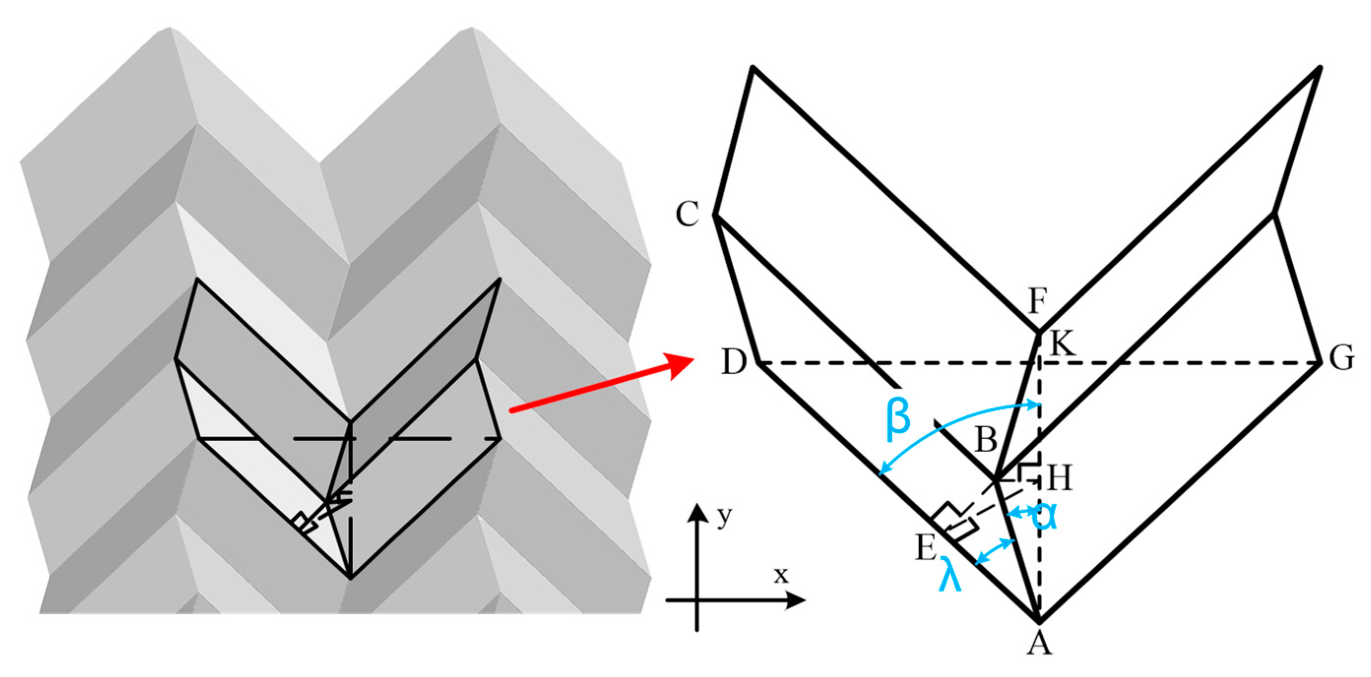
| Length of AB and CD | 1.8 mm |
| Length of AD and BC | 4 mm |
| Degree of λ | 60° |
| Degree of α | 40.89° |
| Degree of β0 | 48.59° |
| Degree of β | 30–50° |
| Properties of Material | Value |
|---|---|
| Elasticity modulus | 1.37 GPa |
| Poisson’s ratio | 0.4 |
| Mass density | 1.12 g/cm3 |
| Line | Slope | Nonlinear Error |
|---|---|---|
| Red line | 3.5 mL/min·mm | 3.2% |
| Blue line | 4.5 mL/min·mm | 0.9% |
Disclaimer/Publisher’s Note: The statements, opinions and data contained in all publications are solely those of the individual author(s) and contributor(s) and not of MDPI and/or the editor(s). MDPI and/or the editor(s) disclaim responsibility for any injury to people or property resulting from any ideas, methods, instructions or products referred to in the content. |
© 2023 by the authors. Licensee MDPI, Basel, Switzerland. This article is an open access article distributed under the terms and conditions of the Creative Commons Attribution (CC BY) license (https://creativecommons.org/licenses/by/4.0/).
Share and Cite
Li, P.; Tian, H.; Li, D.; Wen, Q.; Zhang, Z.; Hu, H. Application of Auxetic Tubular Structure in Flow Control of the Throttle Valve. Energies 2024, 17, 160. https://doi.org/10.3390/en17010160
Li P, Tian H, Li D, Wen Q, Zhang Z, Hu H. Application of Auxetic Tubular Structure in Flow Control of the Throttle Valve. Energies. 2024; 17(1):160. https://doi.org/10.3390/en17010160
Chicago/Turabian StyleLi, Pengju, Hao Tian, Dawei Li, Qingguo Wen, Zhengkai Zhang, and Hong Hu. 2024. "Application of Auxetic Tubular Structure in Flow Control of the Throttle Valve" Energies 17, no. 1: 160. https://doi.org/10.3390/en17010160
APA StyleLi, P., Tian, H., Li, D., Wen, Q., Zhang, Z., & Hu, H. (2024). Application of Auxetic Tubular Structure in Flow Control of the Throttle Valve. Energies, 17(1), 160. https://doi.org/10.3390/en17010160