Article

Performance Potential of a Concentrated Photovoltaic-Electrochemical Hybrid System

1
School of Mechanic and Electronic Engineering, Sanming University, Sanming 365000, China
2
College of New Energy, Ningbo University of Technology, Ningbo 315211, China
*
Authors to whom correspondence should be addressed.
Energies 2024, 17(1), 163; https://doi.org/10.3390/en17010163
Submission received: 3 November 2023 / Revised: 9 December 2023 / Accepted: 20 December 2023 / Published: 28 December 2023
(This article belongs to the Section D2: Electrochem: Batteries, Fuel Cells, Capacitors)

Abstract

:
A novel hybrid system model, combining a concentrated photovoltaic cell (CPC) with a thermally regenerative electrochemical cycle (TREC), is proposed. This innovative setup allows the TREC to convert heat from the CPC into electricity. The model incorporates mathematical equations that explicitly define power output, energy efficiency, and exergy efficiency for both the CPC and the TREC individually, as well as for the hybrid system as a whole. The outcomes of the computations reveal that the hybrid system surpasses the performance metrics of the CPC alone. Specifically, the hybrid system achieves a notably higher maximum power density (MPD), maximum energy efficiency (MEE), and maximum exergy efficiency (MMEE) compared to the standalone CPC, with improvements of 392.68 W m−2, 10.33%, and 11.11%, respectively. Through thorough parametric analyses, it was observed that specific factors positively impact the hybrid system’s performance. These factors include higher operating temperatures, increased solar irradiation, specific concentration ratios, and alterations in the internal resistance or temperature coefficient of the TREC. However, it was noted that elevating the operating temperature of the CPC adversely affects the hybrid system’s performance. Furthermore, augmenting solar irradiation and optical concentration ratios amplifies the limiting electric current. Conversely, reducing the internal resistance of the TREC enhances the overall performance of the hybrid system. These discoveries have practical implications for optimizing the design and operation of a functional CPC-TREC hybrid system, providing valuable insights into maximizing its efficiency and effectiveness.

1. Introduction

Energy is a fundamental resource that is pivotal to driving growth and progress within human societies. Among renewable energies, solar energy is a key contender for addressing energy crises and mitigating the pollution associated with traditional fossil fuels. Its distinct advantages, including direct convertibility, cleanness, abundance, renewability, and lack of pollution, set it apart from conventional energy sources like biomass, solar, hydroelectric, and wind energy. Harnessing solar energy involves various methods such as photoelectric, photothermal, and photochemical conversions. However, the commercial viability of photothermal and photochemical methods is hindered by their high costs, which limit their widespread development. In contrast, photoelectric conversion is one of the most prevalent and accessible methods for utilizing solar energy. Within the category of photoelectric conversion, photovoltaic cells (PVCs) are a prevalent method for the direct conversion of solar energy into electricity. They have been extensively researched owing to their numerous benefits, such as minimal energy consumption during manufacturing, availability of ample raw materials, and extended lifespan.
However, PVCs can convert only a part of incident solar radiation into electrical energy, with the rest converted into heat energy. Moreover, the traditional use of PVCs, with their inherent inefficiencies in converting solar energy, not only increases costs, but also limits the overall effectiveness of the utilization of solar energy. Concentrated photovoltaic cell (CPC) technology utilizes optical instruments to concentrate solar radiation onto a small surface of a PVC [1], which provides many benefits, including affordability, excellent performance, and environmentally friendly characteristics. However, the concentrated solar radiation may lead to a great rise in temperature due to heat accumulation resulting from the thermal effect, which may significantly negatively affect the performance of PVCs. Alternatively, the excess heat generated by CPC technology can be utilized for diverse purposes to enhance the efficiency of energy utilization and prolong the system’s service life. To date, a number of the CPC-based hybrid systems that reuse the waste heat have been developed. For example, Sabry et al. [2] put forward a hybrid system that incorporated both CPC system and a thermoelectric generator (TEG). The results of their study demonstrated that the combined power output of the CPC/TEG hybrid system exhibited a 7.4% increase compared to that of the CPC system operating independently. Another CPC/TEG hybrid system, developed by Rejeb et al. [3], yielded a maximum electrical efficiency of 17.448% under optimal operating conditions. Ceylan et al. [4] proposed a CPC/T solar air-heater system with thermal energy storage, and the overall efficiency and average exergy efficiency were found to be 88% and 10%, respectively. Wang et al. [5] proposed a CPC-photothermochemical hybrid system with overall power-generation efficiency reaching 25.3%.
Moreover, there are several energy-conversion technologies that can efficiently harness low-quality thermal energy, such as thermoelectric generators, organic Rankine cycles, elastocaloric coolers, thermally regenerative electrochemical cycles (TREC), and others. Among these energy converters is TREC, an electrochemical process that relies on the temperature sensitivity of the electrodes. TREC has attracted wide attention due to its low cost, high temperature coefficient and high conversion efficiency [6]. For example, Tang et al. [7] presented a combined PV/thermal-TREC power-generation system that exhibited an increase in electrical efficiency of 0.92% compared to a single PV/thermal module and 0.35% compared to single PV module. Abdollahipour et al. [8] employed TREC to harvest the waste heat from a molten carbonate fuel cell (MCFC) and found that TREC could be a good option for waste-heat recovery. Açıkkalp et al. [9] investigated a phosphoric acid fuel cell (PAFC)/TREC hybrid system and found that the MEE of the hybrid system could be 78.4%. Zhao et al. [10] introduced a hybrid system that coupled TREC to a dye-sensitized solar cell. The hybrid system exhibited an MEE and MPD 32.04% and 32.18% higher than those of the single dye-sensitized solar cell, respectively. Zhang et al. [11] employed TREC to harvest the waste heat from a proton-exchange membrane fuel cell, through which the MPD was enhanced by about 1.11–1.20 times. Guo et al. [12] utilized TREC to harness the waste heat from high-temperature polymer electrolyte membrane fuel cell (HT-PEMFC), and the MPD was increased by 15.6% compared to an HT-PEMFC operating alone. The implementation of the TREC for waste-heat recovery in an alkaline fuel cell (AFC) was examined by Zhang et al. [13], and the efficiency and output power density of the AFC/TREC hybrid system were, respectively, 1.11–1.18 and 1.46–1.77 times higher than those of the AFC operating alone. A literature survey shows that TREC is a potential option for CPC waste-heat recovery. However, there have been no known attempts to utilize TREC to recover waste heat from a CPC; thus, the performance attributes of such a hybrid system remain unexplored.
To address the existing research gap, a pioneering hybrid system model combining a CPC and a TREC is presented. This model defines performance indicators for the CPC, the TREC, and the hybrid system, accounting for diverse irreversible losses. It includes a derived mathematical correlation between the working electric current and rate of waste heat generation by the CPC. Numerical computations are utilized to showcase the advantages of this system. Moreover, multiple parametric investigations are carried out to examine how tweaking key operating conditions and design parameters can potentially improve the hybrid system’s performance.

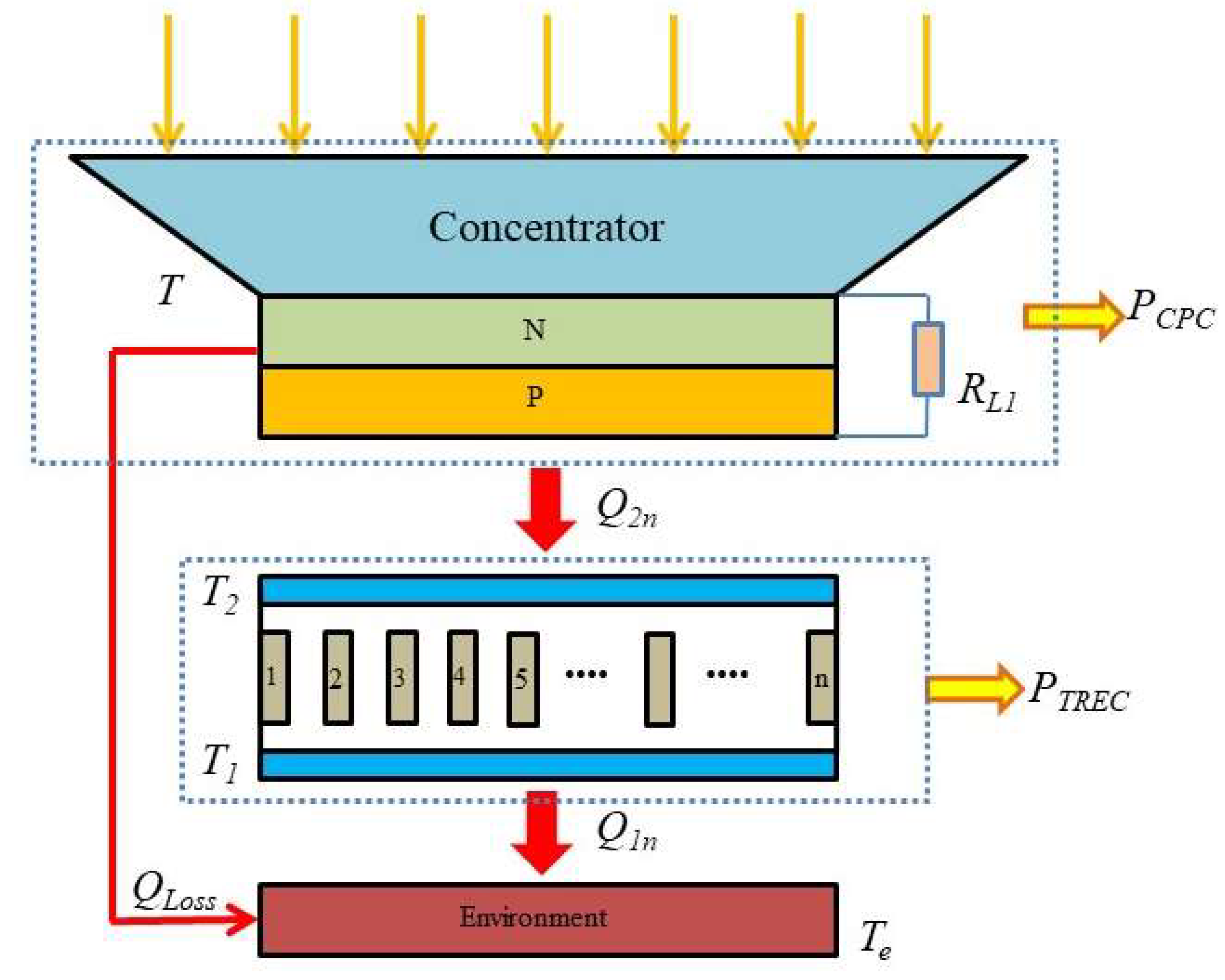
2. System Descriptions

As shown in the visual representation provided in Figure 1, the hybrid system consists of a concentrator, an arrangement of crystalline silicon PV cells within a PV module, and a TREC. The concentrator serves to enhance the incident irradiation intensity by focusing the incoming sunlight onto the PV module [14]. The electrical energy and exhaust heat are generated by the PV module when the concentrated incident irradiation is converted [15]. The exhaust heat is then transferred to the TREC, which is situated in close proximity to the back of the PV module, and converted into electricity.
To assess the overall performance of the hybrid system, each of the two subsystems will be described separately. In order to conduct subsequent analyses, the following assumptions will be adopted:
(1)
A steady-state heat-transfer model in one dimension (1D) is utilized, focusing solely on heat transfer in the vertical direction without considering lateral heat transfer [15];
(2)
The incoming sunlight’s wavelength is converted entirely [16];
(3)
The model does not account for irreversible heat transfer between the CPC and the TREC;
(4)
As the glass cover is quite thin, any temperature gradient along its thickness can be considered negligible [17];
(5)
Operation takes place under steady-state conditions;
(6)
The TREC’s heat-sink temperature is equivalent to the surrounding temperature [10];
(7)
The TREC’s discharging time equals the charging time, in accordance with reference [18];
(8)
The TREC maintains consistent heat capacity, charge capacity, and internal resistance between its charging and discharging phases [19].

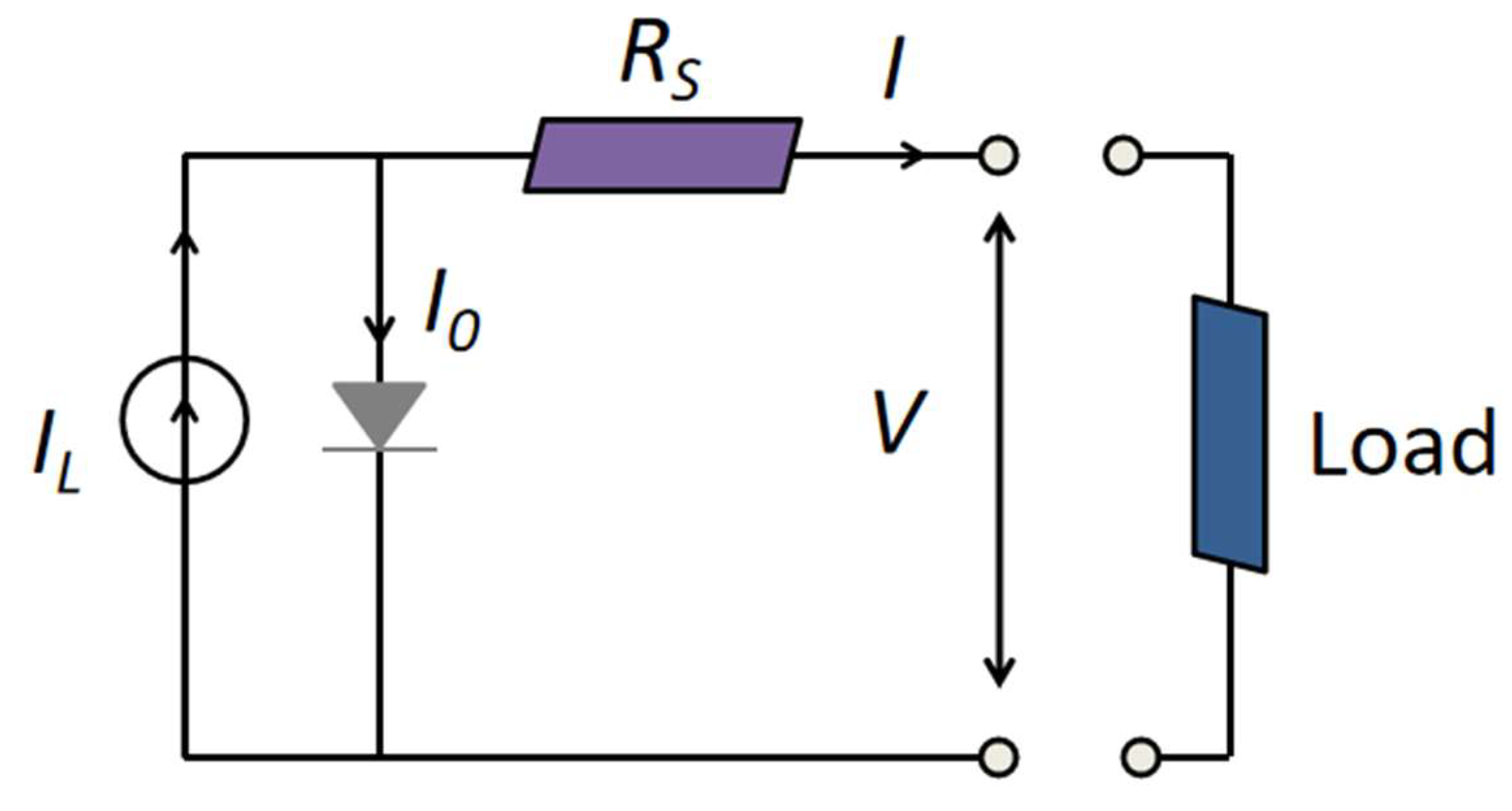
2.1. Concentrated Photovoltaic Cell

As shown in Figure 1, the concentrator and PV module together form the CPC module. The solar irradiance is focused on the PV module surface. Following absorption, a portion of the solar energy is lost through the glass cover by radiation, conduction and convection, and the remaining energy is utilized by the PV module to generate electricity [15]. The energy equilibrium on the absorbing surface of the PV module is expressed as follows [20]:
C G η 0 A P V = Q i n · + ε σ A P V T 4 T e 4 + h A P V T T e
Figure 2 illustrates the PV module’s equivalent circuit, and its correlation J ~ V is expressed by the following equation [20]:
J = n p J L n p J 0 = n p J L n p J S e x p q V + J R S A K b T n s 1
where
J L = G G r C J S C R + K 1 T T r
and
J S = C J r T T r 3 e x p E g q K b 1 T r 1 T
The output voltage of the PV module V can be further solved as
V = A K b T n s q ln n p J L J n p J S + 1 I R S
Consequently, the CPC’s power output P C P C and energy efficiency η C P C can be determined through the following calculations:
P C P C = V J
and
η C P C = P C P C C G η 0 A P V = V J C G η 0 A P V
All the definitions of the variables involved can be found from the nomenclature.

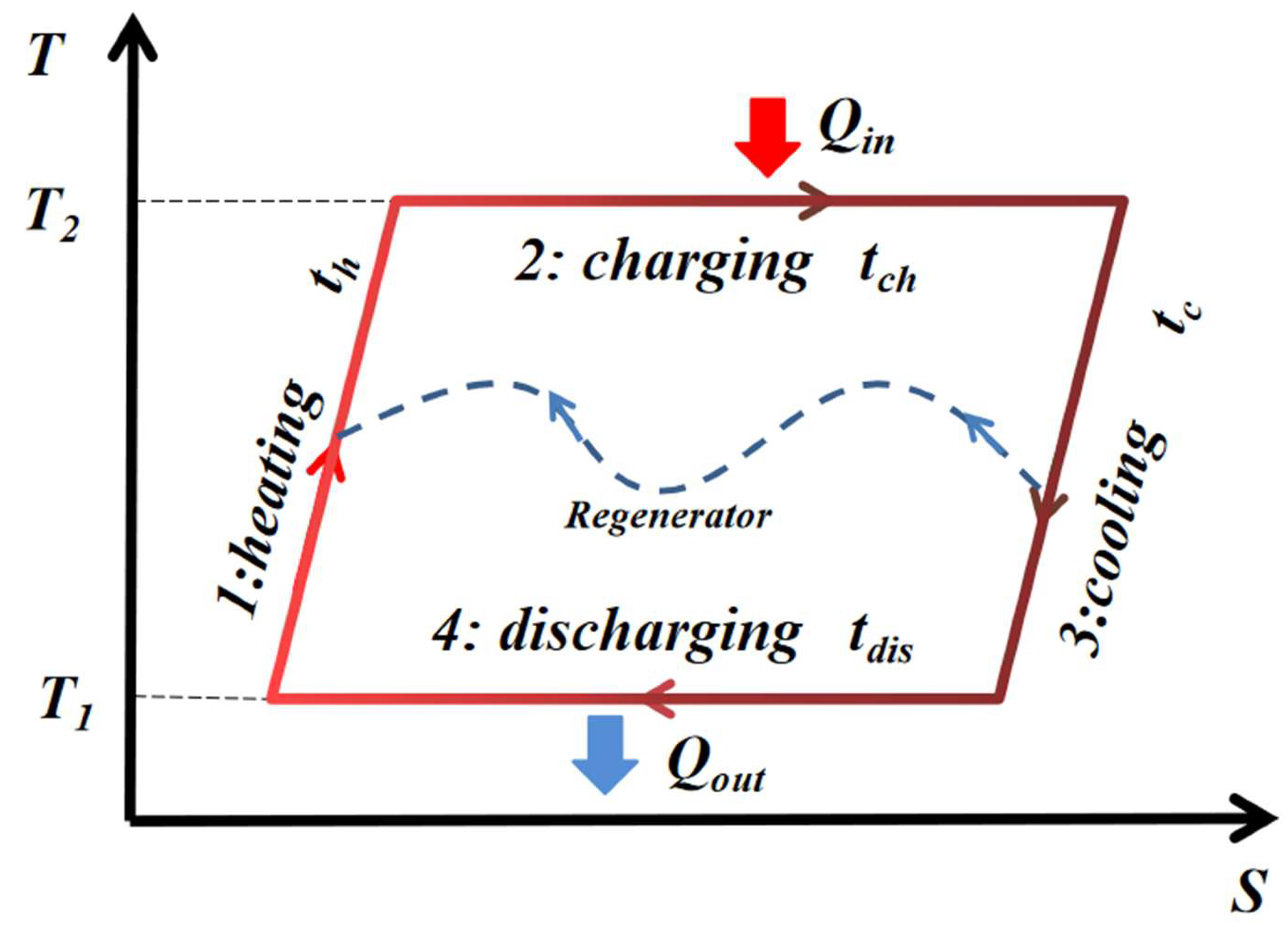
2.2. Thermally Regenerative Electrochemical Cycle

Figure 3 illustrates the alterations in temperature-entropy ( T S ) that occur during each of the four distinct stages in the TREC. The heating process involves elevating the cell’s temperature from T 1 to T 2 while it is not connected to a circuit. Subsequently, in the second process, the cell is charged at a lower voltage at T 2 , during which the electrochemical reaction leads to an increase in the cell’s entropy due to heat absorption. The third stage involves cooling down the cell from T 2 to T 1 under an open circuit, which results in an increase in the open circuit voltage (OCV). In the final stage, the cell undergoes discharge at an elevated voltage at T 1 , and the cell’s entropy decreases as heat is released into the cold reservoir. Following the cycle, the cell returns to its initial state [6]. The net work obtained from the TREC is equivalent to the difference between the energy utilized for charging and the energy released during discharging [13].
The amount of heat taken in from the hot reservoir [18] and the quantity of heat discharged into the cold reservoir [21] during a single cycle of a TREC component can be mathematically represented as follows:
Q 2 * = α c T 2 C q I c h 2 R t c h + 1 η R L C p T 2 T 1
and
Q 1 * = α c T 1 C q I d i s 2 R t d i s + 1 η R L C p T 2 T 1
The cycle time of the TREC, denoted as τ , adheres to the following relationships:
τ = t c h + t d i s + t r
and
n t c h = m τ
where t c h = C q / I c h ; n represents the number of the TRECs and m denotes the number of the cells charging simultaneously [22].
When m 2 , two conditions must be met by both n and m : (1) n / m 2 and (2) n / m N (where N is an integer). A straightforward example would be n = 2 and m = 1 [18]. If the duration of the charging period is the same as that of the discharging period [21], one has
t c h = t d i s = t
and consequently, the charging electric current is equal to the discharging electric current, expressed as
I c h = I d i s = I
Given the significant correlation between the regenerative efficiency and the regenerative time, it becomes possible to estimate the TREC’s regenerative efficiency through the following calculation:
η R L = 2 t r τ = 1 2 m n
The quantity of heat taken in from the hot reservoir and the quantity of heat discharged into the cold reservoir can be expressed as follows:
Q 2 n * = n α c T 2 C q I 2 R t + 2 m n C p T 2 T 1 = m τ α c T 2 I I 2 R + 2 m n C p C q T 2 T 1
and
Q 1 n * = n α c T 1 C q I 2 R t + 2 m n C p T 2 T 1 = m τ α c T 1 I I 2 R + 2 m n C p C q T 2 T 1
Thus, the heat flows during the charging and discharging stages are, respectively, expressed as
Q 2 n = Q 2 n * / τ = m α c T 2 I I 2 R + 2 m n C p C q T 2 T 1
and
Q 1 n = Q 1 n * / τ = m α c T 1 I I 2 R + 2 m n C p C q T 2 T 1
Therefore, the power output P T R E C and efficiency η T R E C of the TREC are, respectively, calculated by
P T R E C = Q 2 n Q 1 n
and
η T R E C = P T R E C Q 2 n = Q 2 n Q 1 n Q 2 n
Definitions of all the variables involved can be found from the nomenclature.

2.3. The Hybrid System
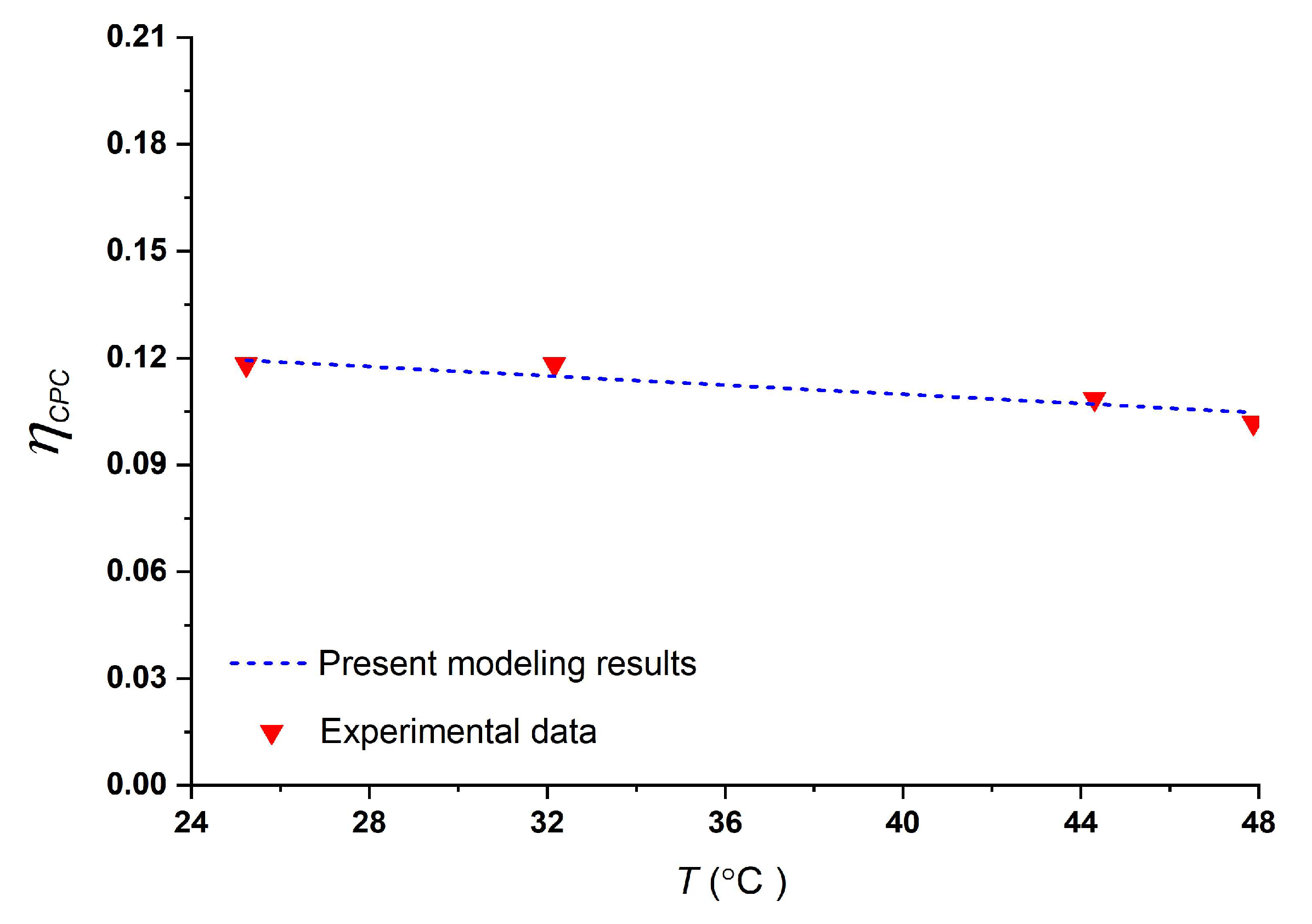
The heat-leakage rate from PV module into the environment is represented by Q L o s s , while the heat flow rate from CPC is denoted by Q 2 n . Their respective formulations are as follows:
Q L o s s = K 0 T H T e
and
Q 2 n = Q i n P P V Q L o s s
The incorporation of the TREC in the hybrid system allows for the computation of the total power output P and energy efficiency η , which can be, respectively, expressed as follows:
P = P C P C + P T R E C
and
η = P C G η 0 A P V = P C P C + P T R E C C G η 0 A P V
Exergy, often termed “available energy”, encompasses the usable portion of energy that can be maximally utilized. Unlike traditional energy analysis, an exergy analysis considers both the first and second laws of thermodynamics. This comprehensive approach provides insights into the factors causing exergy losses during energy-conversion processes, offering a deeper understanding beyond the scope of traditional energy transfers [23].
The exergy balance equation for the CPC-TREC hybrid system can be expressed as follows:
E X i n = E X o u t + I r r e v
Internal irreversibility within the system predominantly stems from heat conduction in the TREC and Joule heating. Conversely, external irreversibility arises from diverse factors. These factors include optical losses caused by the reflection of covered glass, heat exchange between the CPC surface and the surroundings, conversion of solar radiation into low-grade thermal energy, and irreversible heat transfer between the TREC system and the environment.
The total exergy input into the hybrid system per unit time E X i n is expressed as [24]
E X i n = η 0 G A P V 1 4 T e / ( 3 T s u n ) + T e / T s u n 4 / 3
where T s u n is the surface temperature of the sun.
The overall exergy input into the TREC can be represented as
E X i n , T R E C = Q 2 n 1 T e / T
The exergy output by the hybrid system can be expressed as
E X o u t = P C P C + P T R E C
Therefore, the exergy efficiencies of the CPC, TREC, and the hybrid system can be determined through the following calculations:
Ψ C P C = P C P C E X i n = P C P C η 0 G A P V 1 4 T e / ( 3 T s u n ) + T e / T s u n 4 / 3
Ψ T R E C = P T R E C E X i n , T R E C = P T R E C Q 2 n 1 T e / T
and
Ψ = P E X i n = P C P C + P T R E C η 0 G A P V 1 4 T e / ( 3 T s u n ) + T e / T s u n 4 / 3
Definitions of all the variables involved can be found from the nomenclature.

3. Model Validation

Given the absence of experimental research on the proposed hybrid system, the validation process focuses on individually verifying the models of the CPC and TREC. Ensuring the accuracy of these two separate models contributes significantly to validating the proposed hybrid system model to a certain extent. To quantitatively compare the modeling outcomes with experimental data, the average relative error ( A r e ) is calculated using the formula [25]
A r e = 1 n i = 1 n X c a l , i X exp , i X exp , i × 100 %
where X c a l , i and X exp , i are the calculated results and experimental data, respectively.
Figure 4 shows a comparison between the CPC η C P C T efficiency curves obtained from the present model and experimental results from ref. [26]. The results demonstrate a decrease in CPC efficiency as the operating temperature rises. The average relative error is found to be approximately 2.0%.

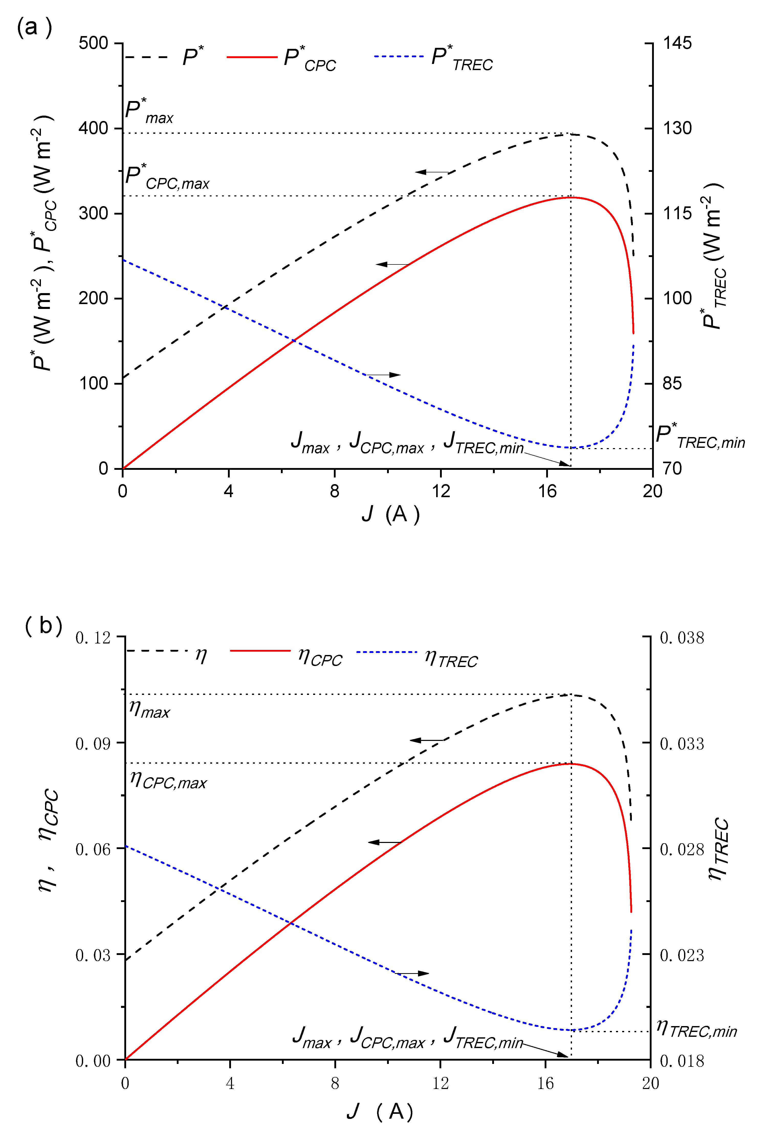
4. Basic Performance Features

Figure 5 shows the variations in the power-output densities, energy efficiencies and exergy efficiencies of the CPC, the TREC, and the hybrid system with respect to the PV module’s operating electric current ( J ). The characteristics of the hybrid system are primarily influenced by the performance of the CPC. As J increases, the values of P * , η , Ψ , and Ψ T R E C gradually increase and then rapidly decrease, while the values of P T R E C * and η T R E C initially decrease slowly and then increase rapidly as J increases. The notable spikes in P T R E C * and η T R E C occur due to a rapid escalation in heat transfer to the TREC. This surge is directly linked to the significant drop in power output from the CPC as J increases. As J increases, P C P C increases but the waste heat released from the CPC decreases. As a result, the heat absorbed by the TREC decreases, leading to a decrease in the power output of the TREC. Numerical calculations using the parameters in Table 1 indicate that P   max * , η max , and Ψ max are 392.68 W m2, 10.33%, and 11.11%, respectively, which are significantly greater than P C P C , max * (318.92 W m2), η C P C , max (8.4%), and Ψ C P C , max (9.02%). It is evident that the hybrid system overperforms the solitary CPC system, and the utilization of the TREC to capture the solar energy that is unusable by CPC proves to be successful. Moreover, due to the fact that the input energy ( Q a l l ) is consistently greater than the input exergy ( E X i n ), the exergy efficiency remains consistently greater than the energy efficiency. It should be noted that J C P C , max , J T R E C , max , J T R E C , min , and J max are equal. From Figure 5, it can be observed that in the range of J > J max , P * , η , and Ψ exhibit a decreasing trend as the operating electric current J is increased. Thus, it can be concluded that the most favorable operating electric current range lies within the range of J J max .

5. Results and Discussion

Subsequent to modeling, a thorough analysis was carried out to investigate the influence of multiple parameters on the hybrid system’s performance. These parameters include the operating temperature of the CPC, solar irradiation, the concentration ratio, the internal resistance and the temperature coefficient of the TREC.

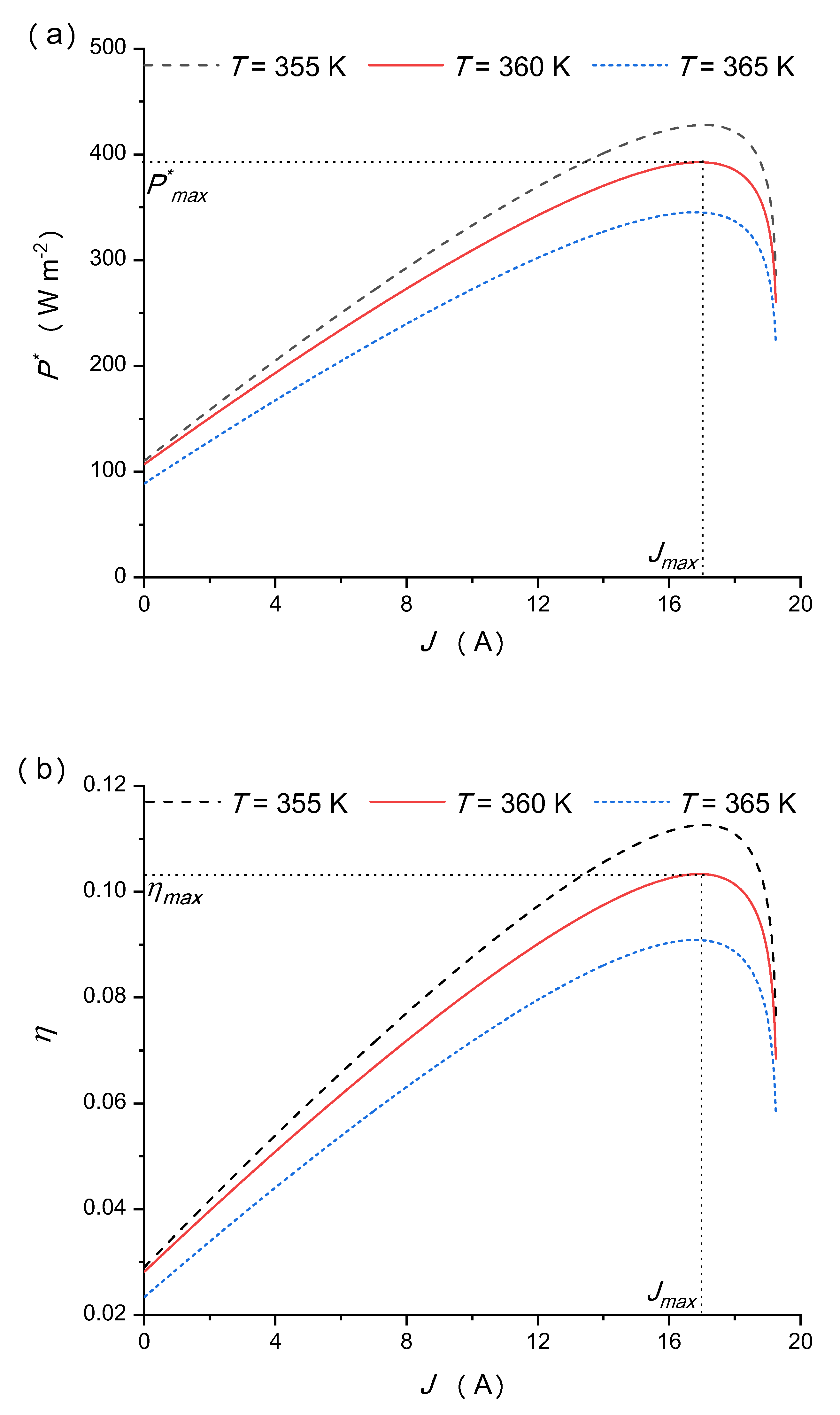
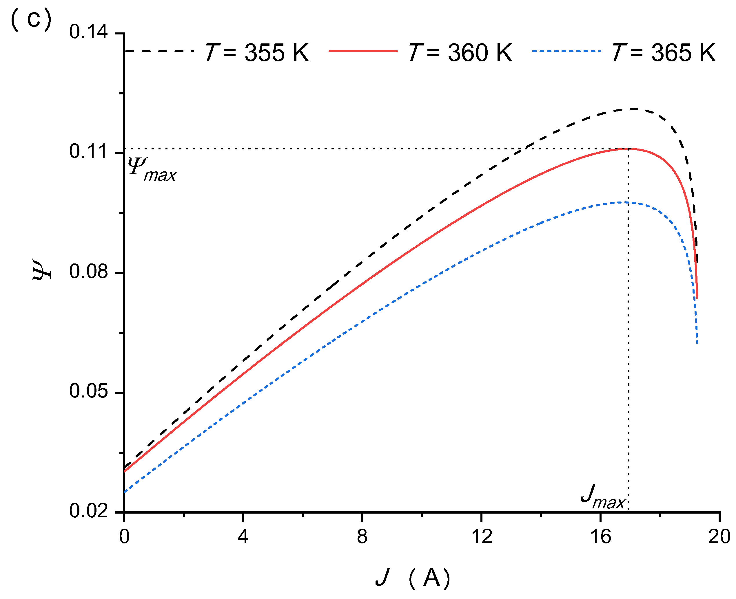
5.1. Effects of the Operating Temperature of the Concentrated Photovoltaic Cell

The performance of the CPC and the TREC are significantly affected by the operating temperature T , which is a critical operating condition. The effects of T on P * , η , and Ψ occur in the whole range of J , as illustrated in Figure 6. Figure 6 indicates that as T increases, P * , η , and Ψ all decrease. The operating T affects the performance of the CPC and TREC differently. A higher value of T adversely affects the performance of the CPC [26], while the performance of the TREC initially improves and then deteriorates. As the increase in T results in a greater performance degradation in CPC than the performance improvement contributed by TREC, the hybrid system’s performance is negatively impacted. Reducing the value of T is always an effective way to enhance the overall hybrid system performance, confirming the importance of the CPC heat management. The impact of T on the performance is particularly pronounced when J is close to J max . With the parameters specified in Table 1, J max remains relatively stable as T varies. In practical applications, a balance between the performance of the CPC and TREC at different temperatures should be sought, possibly through experimental validation or sophisticated modeling techniques to identify the optimal operating temperature for the hybrid system.

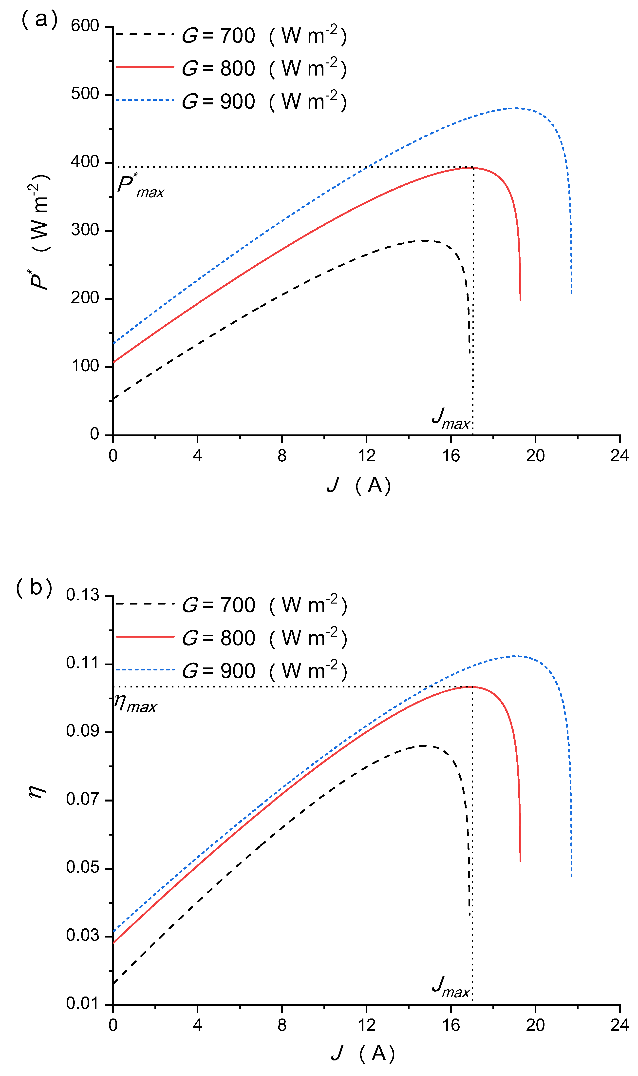
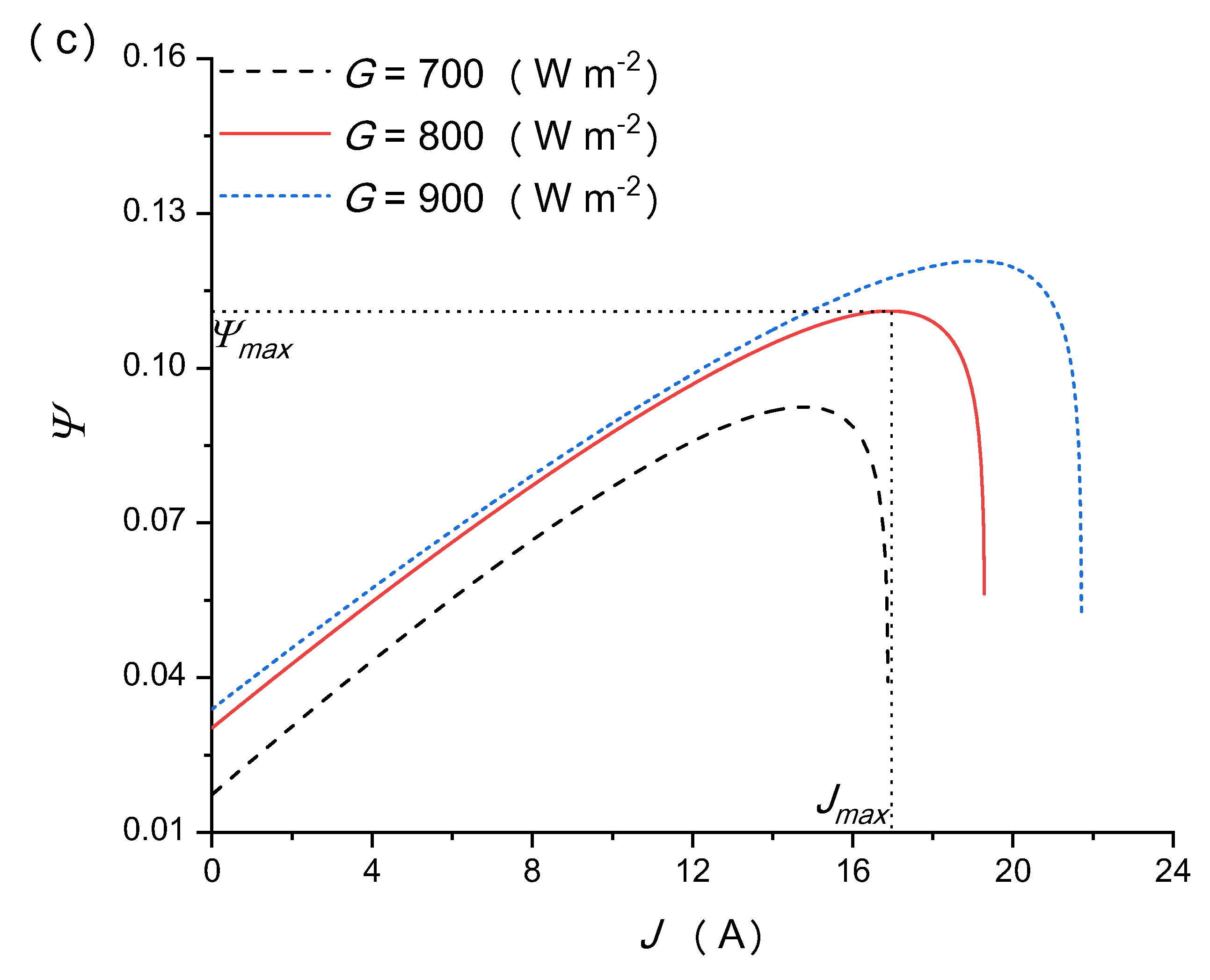
5.2. Effects of the Solar Irradiation

The performance of both CPC and TREC is significantly influenced by the solar irradiation G . When G increases, more solar energy enters into the CPC per unit time, resulting in an increase in the output power density of both CPC and TREC. The data presented in Figure 7 confirms that as the value of G increases, there is a corresponding increase in P * , η and Ψ . More solar radiation results in a larger portion of the incident solar radiation being converted into heat, which in turn increases the output power density of both the CPC and the heat transferred to the TREC, thereby improving the energy utilization of the hybrid system. As the solar radiation G increases, the upper limit of the operating electric current for the hybrid system also increases. Solar irradiation is affected by various natural conditions such as season, weather conditions, latitude, altitude, etc. To maximize the capture of solar energy, various solar-tracking systems have been developed. Solar irradiation is influenced by multiple natural conditions, like seasonal changes, weather variations, latitude, altitude, and more.

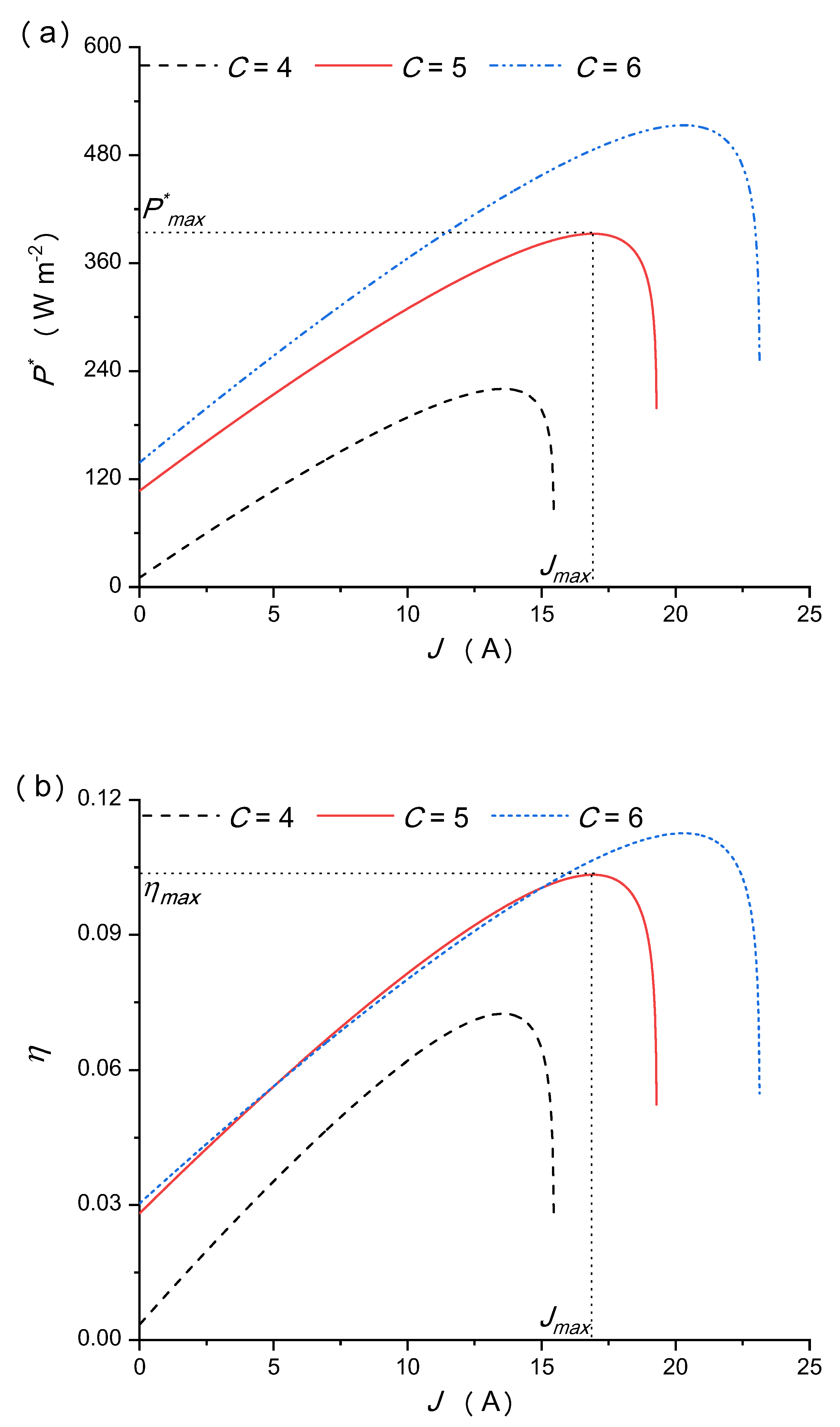
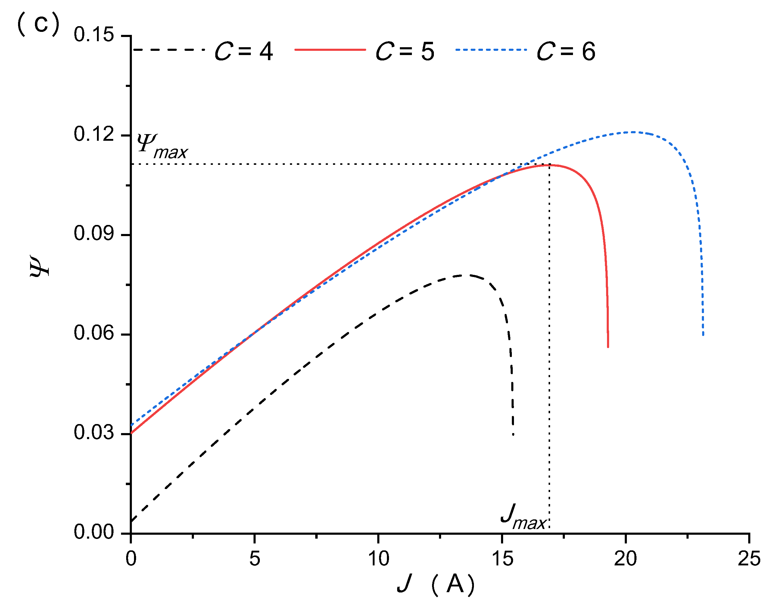
5.3. Effects of the Concentration Ratio

The concentration ratio C significantly influences the CPC’s performance, thereby affecting the performance of the TREC. A higher C leads to a greater amount of solar energy being directed toward the CPC per unit area and time, thereby enhancing the efficiency of both the CPC and the TREC. From Figure 8, it can be observed that P * obviously increases as C increases, while the impacts of C on η and Ψ are not significant. This difference is due to the fact that the rise in P * is not as significant as that of E x i n . As C increases, the operational electric currents at P max * , η max , and Ψ max and the limiting electric current J max exhibit growth. The reason behind this result is the strong correlation between TREC performance and CPC heat, which is enhanced by a higher value of C , resulting in greater solar energy density and improved heat transfer from the CPC to the TREC. This finding suggests that increasing the value of C can enhance the output power density, but it also entails higher manufacturing costs and more stringent requirements for the concentrator materials.

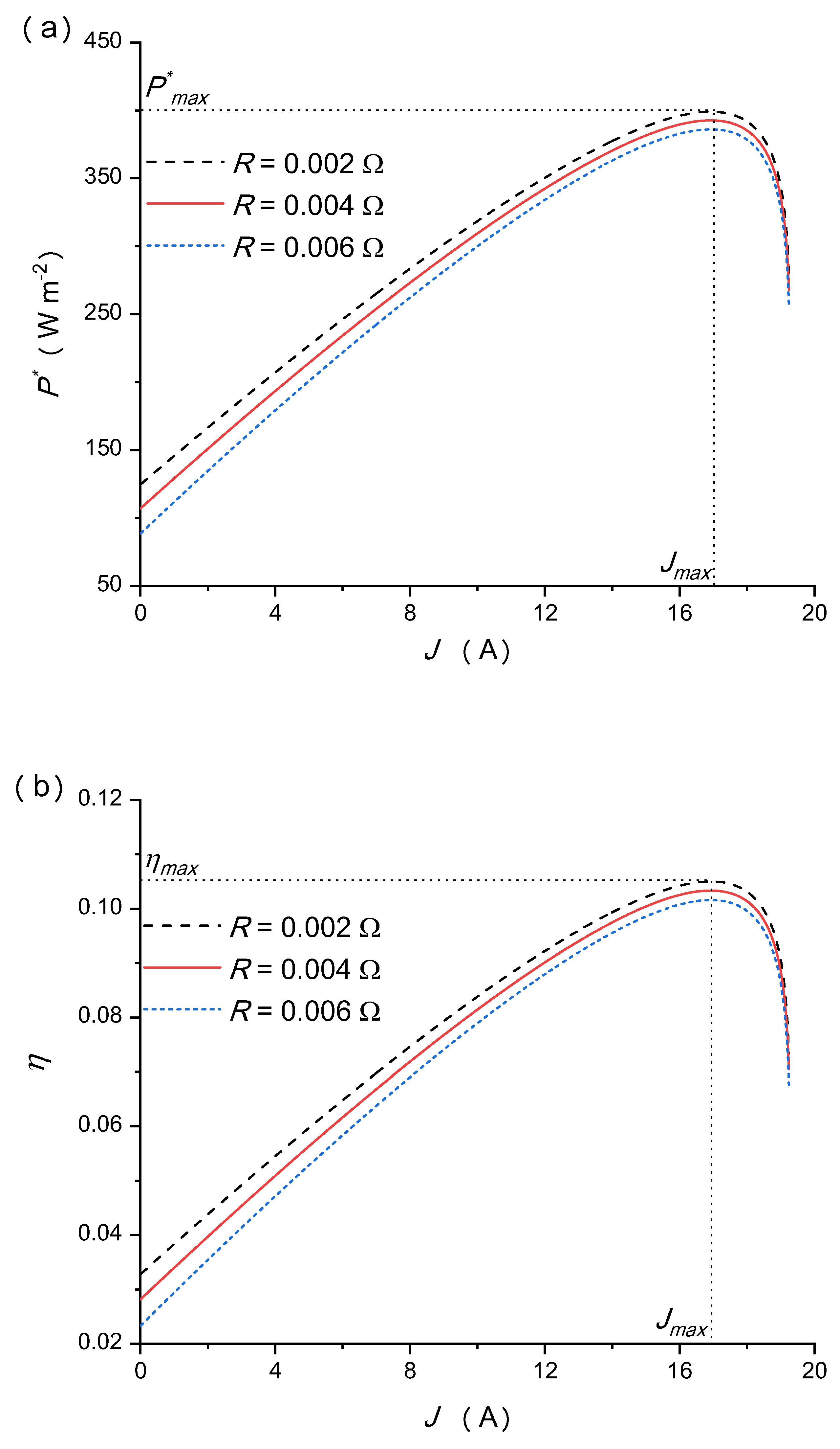
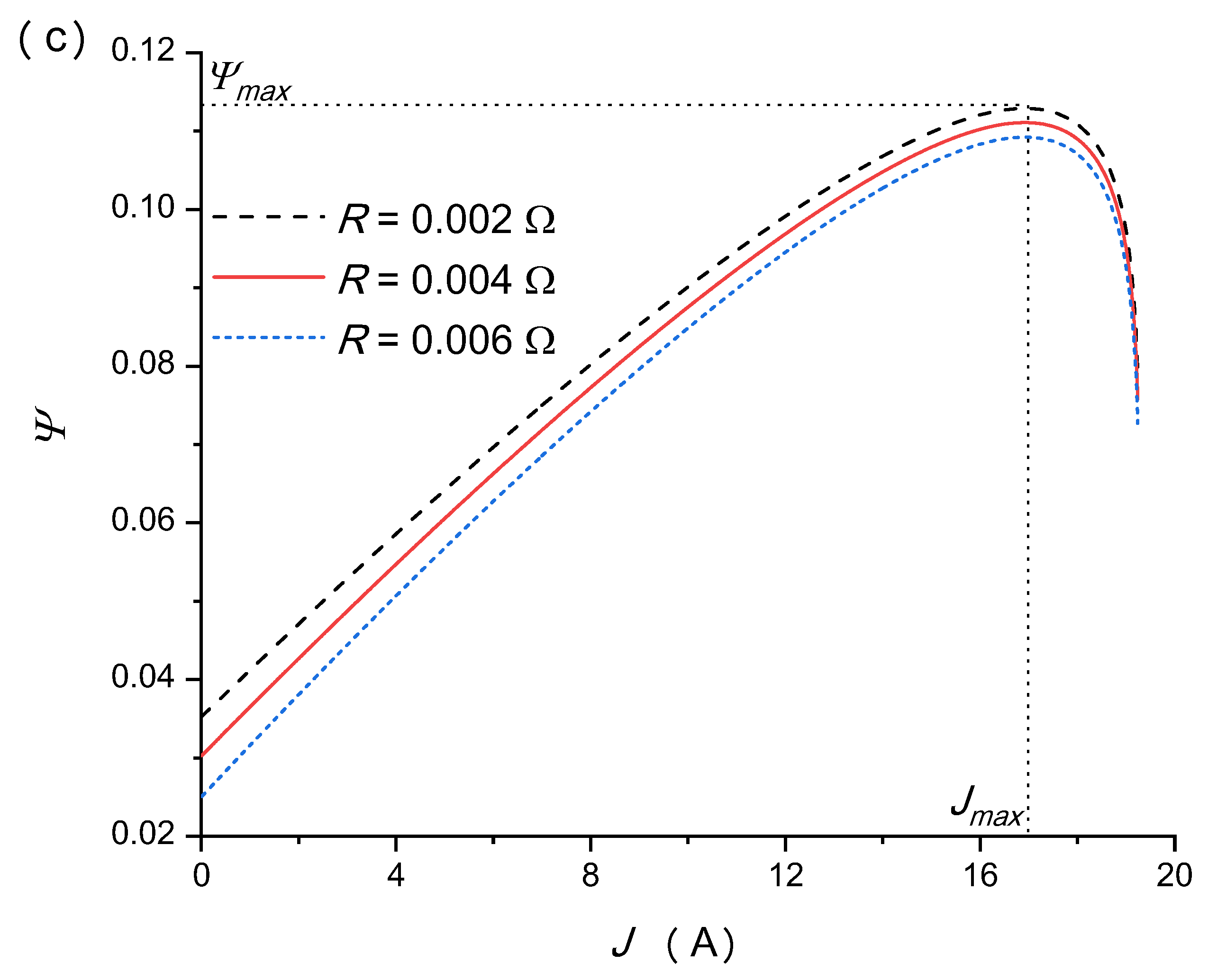
5.4. Effects of the Internal Resistance of Thermally Regenerative Electrochemical Cycle

The performance of both the TREC and the overall hybrid system are significantly impacted by the TREC’s internal resistance R , making it a crucial factor to consider. Figure 9 illustrates that the reduction in R results in improvements in P * , η , and Ψ . The effects manifest in two main ways. Initially, internal resistance shapes the current density within cells. Lower density diminishes the strength of the electrochemical reaction, leading to reduced electrical power output. Hence, heightened internal resistance reduces current density, negatively impacting efficiency. Subsequently, internal resistance alters the distribution of heat arising from electrochemical reactions. In TREC systems, higher current densities increase heat generation. Increased internal resistance might absorb too much of this heat, ultimately decreasing system efficiency. When I is relatively small, the impact of R on the hybrid system’s performance is pronounced; however, when I exceeds I max , the influence of R gradually diminishes. Hence, decreasing the TREC’s internal resistance and operating at an appropriate value of I are essential to effectively enhancing the hybrid system’s performance.

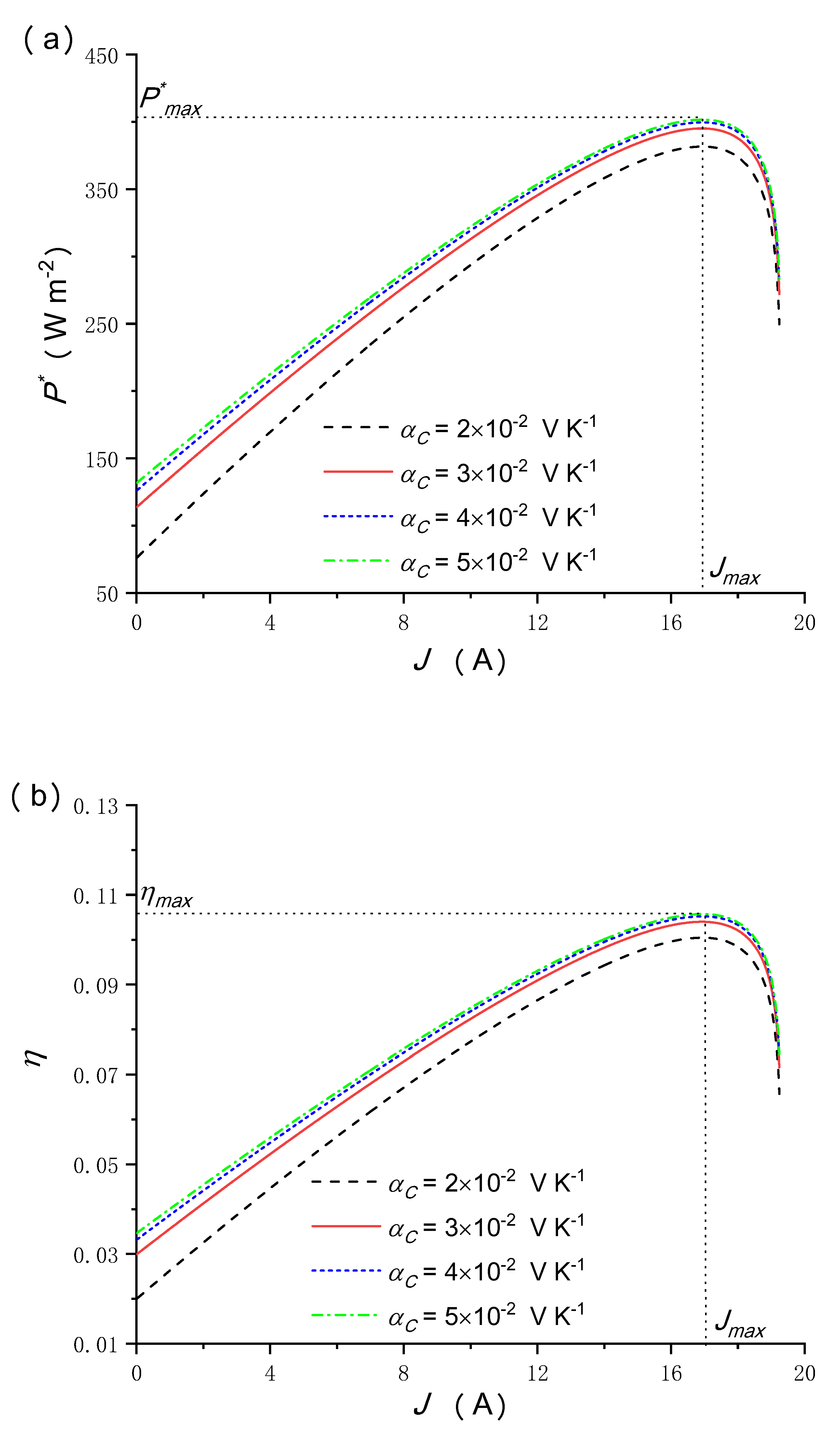
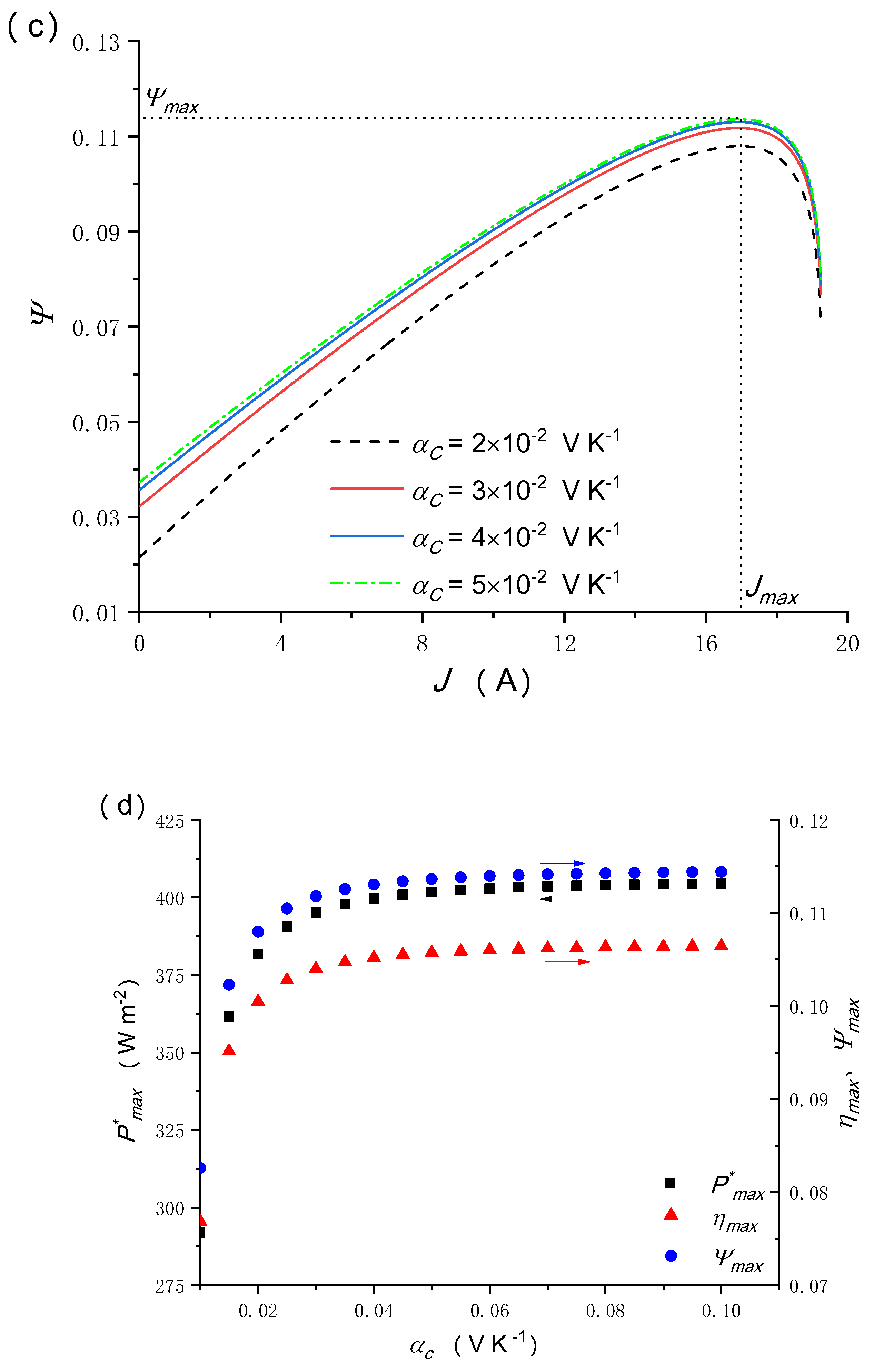
5.5. Effects of the Temperature Coefficient

The temperature coefficient characterizes alterations in potential generated by an electrochemical reaction across diverse temperatures. Its significance lies in quantifying the potential change per unit temperature shift. A minute temperature coefficient diminishes the efficiency of thermal regeneration. Moreover, it shapes the TREC system’s capabilities, where a greater coefficient enhances the system’s capacity to convert thermal energy into electrical energy effectively. An increase in the value of this coefficient enhances the hybrid system’s performance, boosting its overall efficiency. The performance of the TREC is significantly influenced by the temperature coefficient a c , which, in turn, impacts the overall performance of the hybrid system. Figure 10 indicates that P * , η , and Ψ exhibit enhancement with an increase in a c , and the impact of a c becomes less pronounced as I rises. It is noteworthy that when a c surpasses 6.0 × 10⁻³ V K−1, P * max , η max , and Ψ max become less sensitive to changes in a c . Therefore, selecting an appropriate value for a c is crucial to effectively enhancing the performance of the hybrid system. This finding suggests that beyond this threshold, the system might reach a state where further increases in a c do not significantly impact these variables. Therefore, optimizing the value of a c within a specific range becomes crucial to effectively enhancing the performance of the hybrid system without encountering diminishing returns.

6. Conclusions

A novel hybrid system model, which combines a CPC and a TREC, is proposed to fully utilize the inlet solar spectra. The relationship between the operating electric current of the PV module and the exhaust heat of the CPC, as well as the cycle time, was analyzed mathematically. The hybrid system exhibits an increase in MPD, MEE, and MMEE by 392.68 W m−2, 10.33% and 11.11%, respectively, compared to the performance of the CPC alone, as indicated by the results of the numerical calculations. Multiple design parameters and operating conditions, including the TREC internal resistance, the temperature coefficient, solar irradiation, the operating temperature of the CPC, and the concentration ratio, are investigated. The results of comprehensive parametric studies suggest that optimizing these factors can improve the hybrid system’s performance. Specifically, reducing the internal resistance of the TREC, increasing the solar irradiation and optical concentration ratio, and employing an appropriate temperature coefficient can enhance the hybrid system’s performance. However, increasing the operating temperature of the CPC can lead to a decrease in the hybrid system’s performance. Overall, the findings of this study provide valuable guidance for the operation and design of a real CPC/TREC hybrid system.

Author Contributions

Y.L.: Conceptualization, Data Curation, Writing—Original draft preparation; R.X.: Writing—Review & Editing; L.C.: Data Curation, Writing—Original draft preparation; H.Z.: Supervision, Resources, Writing—Review & Editing. All authors have read and agreed to the published version of the manuscript.

Funding

This work has been supported by the Fujian Province Young and Middle-aged Teacher Education Research Project (No. JAT190722/B201935, JAT200624/B202015), Natural Science Foundation of Fujian Province (No. 2023J01162), the National Science Foundation of China (No.11804189), China.

Data Availability Statement

Data are contained within the article.

Conflicts of Interest

The authors declare that they have no known competing financial interests or personal relationships that could have appeared to influence the work reported in this paper.

Nomenclature

A Diode ideality factor
A P V Area of PV module (m2)
C Optical concentration ratio
C p Heat capacity (J kg−1 K−1)
C q Charge capacity (A s−1 kg−1)
E g Band-gap energy of the semiconductor materials used in the PV (eV)
E X i n Total exergy input into the hybrid system per unit time
E X o u t Exergy output of the hybrid system per unit time
E X i n , T R E C Total exergy input into the TREC
G Solar irradiation (W m−2)
G r Reference solar irradiation (W m−2)
h Heat-transfer coefficient of the PV surface
I c h Charge process current (A)
I d i s Discharge process current (A)
I r r e v Losses of the internal irreversibility and external irreversibility in the coupling system
J PV array output current (A)
J L Photocurrent (A)
J S Diode reverse saturation current (A)
J 0 Diode reverse current (A)
J S C R Cell short-circuit current at reference temperature and radiation (A)
K 0 Overall heat-leak coefficient
K 1 Short-circuit current temperature coefficient
K b Boltzmann constant (J K−1)
n p Number of cells in parallel
n s Number of cells in series
n Number of the TRECs
m Number of cells charging simultaneously
P Electric power output of the hybrid system (W)
P * Electric output power density of the hybrid system (W m−2)
P C P C * Electric output power density of the CPC (W m−2)
P T R E C * Electric output power density of the TREC (W m−2)
P C P C Electric power output of the CPC (W)
P T R E C Electric power output of the TREC (W)
q Charge of an electron (C)
Q i n · Solar energy transferred to the PV module per unit time (W m−2)
Q 1 * Heat absorbed from the heat released to the cold reservoir during the cycle time (W m−2)
Q 2 * Heat absorbed from the hot reservoir to the cold reservoir during the cycle time (W m−2)
Q 2 n Rate of heat flowing from CPC to TTEG (W m−2)
Q L o s s Rate of heat leaked from the CPC to the environment (W m−2)
Q 2 n * Heat absorbed from the hot reservoir to the cold reservoir for a TREC consisting of n TREC elements (W m−2)
Q 1 n * Heat absorbed from the heat released to the cold reservoir for a TREC consisting of n TREC elements (W m−2)
R S Intrinsic series resistance of the PV cell (Ω)
R L 1 Load resistances of the CPC module (Ω)
T Operating temperature of the CPC (K)
T 1 Temperature of cold source (K)
T 2 Temperature of heat source (K)
T r PV cell reference temperature (K)
T e Environment temperature (K)
T s u n Surface temperature of the sun (K)
t Time
t c h Time of charge process
t d i s Time of discharge process
t r Time of recombination process
V Output voltage of PV module
v Wind velocity (m/s)
Greek symbols
ε Emittance of the selective surface facing the incoming solar radiation
σ Stefan-Boltzmann constant
τ Cycle time of the TREC
η Efficiency of the hybrid system
η 0 Optical energy of the concentrator
η R L Efficiency of regenerative losses
η C P C Efficiency of the CPC
η T R E C Efficiency of the TREC
α c Temperature coefficient (V K−1)
Ψ C P C Exergy efficiencies of the CPC
Ψ T R E C Exergy efficiencies of the TREC
Ψ Exergy efficiencies of the hybrid system
Subscripts
CPCConcentrated photovoltaic cell
maxMaximum
minMinimum
Acronyms
MEEMaximum energy efficiency
MPDMaximum power density
MMEEMaximum exergy
PVCsPhotovoltaic cells
TRECThermally regenerative electrochemical cycle
T-STemperature-entropy

References

  1. Ejaz, A.; Babar, H.; Ali, H.M.; Jamil, F.; Janjua, M.M.; Fattah, I.M.R.; Said, Z.; Li, C. Concentrated photovoltaics as light harvesters: Outlook, recent progress, and challenges. Sustain. Energy Technol. Assess. 2021, 46, 101199. [Google Scholar] [CrossRef]
  2. Sabry, M.; Lashin, A.; Al Turkestani, M. Experimental and simulation investigations of CPV/TEG hybrid system. J. King Saud Univ. Sci. 2021, 33, 101321. [Google Scholar] [CrossRef]
  3. Rejeb, O.; Shittu, S.; Ghenai, C.; Li, G.; Zhao, X.; Bettayeb, M. Optimization and performance analysis of a solar concentrated photovoltaic-thermoelectric (CPV-TE) hybrid system. Renew. Energy 2020, 152, 1342–1353. [Google Scholar] [CrossRef]
  4. Ceylan, İ.; Gürel, A.E.; Ergün, A.; Guma, İ.H.G.; Ağbulut, Ü.; Yıldız, G. A detailed analysis of CPV/T solar air heater system with thermal energy storage: A novel winter season application. J. Build. Eng. 2021, 42, 103097. [Google Scholar] [CrossRef]
  5. Wang, Y.; Li, Q.; Li, D.; Hong, H. Thermodynamic analysis for a concentrating photovoltaic-photothermochemical hybrid system. Energy 2018, 148, 528–536. [Google Scholar] [CrossRef]
  6. Long, R.; Li, B.; Liu, Z.; Liu, W. Performance analysis of a thermally regenerative electrochemical cycle for harvesting waste heat. Energy 2015, 87, 463–469. [Google Scholar] [CrossRef]
  7. Tang, X.; Li, G.; Zhao, X. Performance analysis of a novel hybrid electrical generation system using photovoltaic/thermal and thermally regenerative electrochemical cycle. Energy 2021, 232, 120998. [Google Scholar] [CrossRef]
  8. Abdollahipour, A.; Sayyaadi, H. Thermal energy recovery of molten carbonate fuel cells by thermally regenerative electrochemical cycles. Energy 2021, 227, 120489. [Google Scholar] [CrossRef]
  9. Açıkkalp, E.; Ahmadi, M.H. Parametric investigation of phosphoric acid fuel cell—Thermally regenerative electro chemical hybrid system. J. Clean. Prod. 2018, 203, 585–600. [Google Scholar] [CrossRef]
  10. Zhao, Q.; Guo, X.; Zhang, H.; Ni, M.; Hou, S. Performance evaluation of a novel photovoltaic-electrochemic hybrid system. Energy Convers. Manag. 2019, 195, 1227–1237. [Google Scholar] [CrossRef]
  11. Zhang, X.; Pan, Y.; Cai, L.; Zhao, Y.; Chen, J. Using electrochemical cycles to efficiently exploit the waste heat from a proton exchange membrane fuel cell. Energy Convers. Manag. 2017, 144, 217–223. [Google Scholar] [CrossRef]
  12. Guo, X.; Zhang, H. Performance analyses of a combined system consisting of high-temperature polymer electrolyte membrane fuel cells and thermally regenerative electrochemical cycles. Energy 2020, 193, 116720. [Google Scholar] [CrossRef]
  13. Zhang, X.; Cai, L.; Liao, T.; Zhou, Y.; Zhao, Y.; Chen, J. Exploiting the waste heat from an alkaline fuel cell via electrochemical cycles. Energy 2018, 142, 983–990. [Google Scholar] [CrossRef]
  14. Najafi, H.; Woodbury, K.A. Optimization of a cooling system based on Peltier effect for photovoltaic cells. Sol. Energy 2013, 91, 152–160. [Google Scholar] [CrossRef]
  15. Lamba, R.; Kaushik, S.C. Solar driven concentrated photovoltaic-thermoelectric hybrid system: Numerical analysis and optimization. Energy Convers. Manag. 2018, 170, 34–49. [Google Scholar] [CrossRef]
  16. Guo, X.-Z.; Zhang, Y.-D.; Qin, D.; Luo, Y.-H.; Li, D.-M.; Pang, Y.-T.; Meng, Q.-B. Hybrid tandem solar cell for concurrently converting light and heat energy with utilization of full solar spectrum. J. Power Sources 2010, 195, 7684–7690. [Google Scholar] [CrossRef]
  17. Lamba, R.; Kaushik, S.C. Modeling and performance analysis of a concentrated photovoltaic–thermoelectric hybrid power generation system. Energy Convers. Manag. 2016, 115, 288–298. [Google Scholar] [CrossRef]
  18. Wang, Y.; Cai, L.; Peng, W.; Zhou, Y.; Chen, J. Maximal continuous power output and parametric optimum design of an electrochemical system driven by low-grade heat. Energy Convers. Manag. 2017, 138, 156–161. [Google Scholar] [CrossRef]
  19. Long, R.; Li, B.; Liu, Z.; Liu, W. Ecological analysis of a thermally regenerative electrochemical cycle. Energy 2016, 107, 95–102. [Google Scholar] [CrossRef]
  20. Liao, T.; Lin, B.; Yang, Z. Performance characteristics of a low concentrated photovoltaic–thermoelectric hybrid power generation device. Int. J. Therm. Sci. 2014, 77, 158–164. [Google Scholar] [CrossRef]
  21. Long, R.; Li, B.; Liu, Z.; Liu, W. Performance analysis of a dual loop thermally regenerative electrochemical cycle for waste heat recovery. Energy 2016, 107, 388–395. [Google Scholar] [CrossRef]
  22. Ni, M.; Leung, M.K.H.; Leung, D.Y.C.; Sumathy, K. An analytical study of the porosity effect on dye-sensitized solar cell performance. Sol. Energy Mater. Sol. Cells 2006, 90, 1331–1344. [Google Scholar] [CrossRef]
  23. Lai, C.; Zhao, Q.; Zhang, Z.; Zhang, H.; Hou, S.; Zhao, J. Potential evaluation of flexible annular thermoelectric generator in photovoltaic system performance improvement: Energy and exergy perspectives. Energy Convers. Manag. 2021, 247, 114711. [Google Scholar] [CrossRef]
  24. Fitra, M.; Daut, I.; Irwanto, M.; Gomesh, N.; Irwan, Y.M. Effect of TiO2 Thickness Dye Solar Cell on Charge Generation. Energy Procedia 2013, 36, 278–286. [Google Scholar] [CrossRef]
  25. Wu, S.-Y.; Zhong, Z.-H.; Xiao, L.; Chen, Z.-L. Performance analysis on a novel photovoltaic-hydrophilic modified tubular seawater desalination (PV-HMTSD) system. Desalination 2021, 499, 114829. [Google Scholar] [CrossRef]
  26. Kong, C.; Xu, Z.; Yao, Q. Outdoor performance of a low-concentrated photovoltaic–thermal hybrid system with crystalline silicon solar cells. Appl. Energy 2013, 112, 618–625. [Google Scholar] [CrossRef]
Figure 1. Schematic diagram of a hybrid system composed of a CPC and a TREC.
Energies 17 00163 g001
Figure 2. Equivalent electric circuit of the PV module.
Energies 17 00163 g002
Figure 3. T-S diagram of a TREC system.
Energies 17 00163 g003
Figure 4. Comparison of the CPC η C P C T curves between the present CPC modeling results and the experimental results from ref. [26], where the experimental solar module includes 18 pieces of series-connected solar cells pasted on an aluminum receiver with thermal conductivity silica gel.
Energies 17 00163 g004
Figure 5. Comparisons of (a) power-output densities, (b) energy efficiencies and (c) exergy efficiencies between the CPC, the hybrid system and the TREC, where P C P C * = P C P C / A P V , P * = P / A P V and P T R E C * = P T R E C / A P V ; P * and P C P C * are, respectively, the power-output densities of the hybrid system and CPC; P T R E C * is the output power density of the TREC, P C P C , max * and P max * are, respectively, the maximum power output densities of the CPC and the hybrid system; P T R E C , min * is the minimum output power density of the TREC; η C P V , η and η T R E C are, respectively, the energy efficiencies of the CPC, the hybrid system and the TREC; η C P C , max and η max are, respectively, the maximum energy efficiencies of the CPC and the hybrid system; η T R E C , min is the minimum energy efficiency of the TREC; Ψ , Ψ C P C and Ψ T R E C are, respectively, the exergy efficiencies of the hybrid system, the CPC and the TREC; Ψ max , Ψ C P C , max and Ψ T R E C , max are, respectively, the maximum exergy efficiencies of the hybrid system, the CPC and the TREC; J C P C , max and J max are, respectively, the corresponding operating electric currents at P C P C , max * and P max * (or η C P C , max and η max ); J T R E C , min is the corresponding operating electric current at P T R E C , min * (or η T R E C , min ); J T R E C , max is the corresponding operating electric current at Ψ T R E C , max .
Energies 17 00163 g005aEnergies 17 00163 g005b
Figure 6. The influence of operating temperature T on (a) output power density, (b) energy efficiency and (c) exergy efficiency of the hybrid system.
Energies 17 00163 g006aEnergies 17 00163 g006b
Figure 7. The influence of solar irradiation G on (a) output power density, (b) energy efficiency and (c) exergy efficiency of the hybrid system.
Energies 17 00163 g007aEnergies 17 00163 g007b
Figure 8. The influence of concentration ratio C on (a) output power density, (b) energy efficiency and (c) exergy efficiency of the hybrid system.
Energies 17 00163 g008aEnergies 17 00163 g008b
Figure 9. The influence of the TREC internal resistance R on (a) output power density, (b) energy efficiency and (c) exergy efficiency of the hybrid system.
Energies 17 00163 g009aEnergies 17 00163 g009b
Figure 10. The influence of the temperature coefficient on (a) output power density, (b) energy efficiency and (c) exergy efficiency of the hybrid system; and (d) maximum output power density; energy efficiency and exergy efficiency of the hybrid system as a function of the temperature coefficient at J = 16.9   A .
Energies 17 00163 g010aEnergies 17 00163 g010b
Table 1. Parameters used in the modeling of the CPC/TREC hybrid system.
ParametersValues
A 1.0 [20]
K 1 (mA K−1) 2.06 [20]
C 5.0 [20]
I r (μA) 0.118 [20]
K b 1.380 × 10⁻²³ [20]
q 1.602 × 10⁻¹⁹ [20]
σ (W m−2 K−4) 5.67 × 10⁻⁸ [20]
ε 0.85 [20]
K 0 (W K−1) 20
A p v (m2) 0.632 [20]
n p 1.0 [20]
n s 36.0 [20]
G r (W m−2) 1000.0 [20]
G (W m−2) 800.0 [20]
E g (V) 1.12 [20]
T r (K) 300.0 [20]
T e (K) 308.0 [20]
R (Ω) 0.004 [10]
a c (V K−1) 0.027 [10]
m 1.0 [18]
n 2.0 [18]
T 2 (K) 360.0
T 1 (K) 308.0
C p (J kg−1 K−1) 2.408 [18]
C q (A h kg−1) 32.43 [18]
Disclaimer/Publisher’s Note: The statements, opinions and data contained in all publications are solely those of the individual author(s) and contributor(s) and not of MDPI and/or the editor(s). MDPI and/or the editor(s) disclaim responsibility for any injury to people or property resulting from any ideas, methods, instructions or products referred to in the content.

