Article

Study on the Effect of Coupled Internal and External EGR on Homogeneous Charge Compression Ignition under High Pressure Rise Rate

1
Sinopec Research Institute of Petroleum Processing, Beijing 100083, China
2
State Key Laboratory of Automotive Simulation and Control, Jilin University, Changchun 130025, China
*
Author to whom correspondence should be addressed.
Energies 2024, 17(1), 175; https://doi.org/10.3390/en17010175
Submission received: 18 November 2023 / Revised: 24 December 2023 / Accepted: 26 December 2023 / Published: 28 December 2023
(This article belongs to the Section I2: Energy and Combustion Science)

Abstract

:
This paper investigated the effects of exhaust gas recirculation (EGR) on homogeneous charge compression ignition (HCCI) combustion in internal combustion engines. The exhaust valve closing (EVC) timings were scanned to obtain a set of baseline operating points for HCCI, and the coupling control of the internal and external EGR was explored. The results indicate that external EGR delays HCCI ignition timing and slows down the combustion speed. As the internal EGR rate increases, the maximum external EGR ratio that can be tolerated decreases. For HCCI detonation operating points with low internal EGR rates, the addition of up to 10% of external EGR can control the pressure rise rate peak to less than 10 bar/°CA, resulting in reduced fuel consumption and increased indicated mean effective pressure (IMEP). However, for HCCI operating points with high internal EGR rates, the effect of external EGR is mainly observed in the control of the pressure rise rate, with limited increase in IMEP. Additionally, an increasing external EGR rate leads to a significant decrease in nitrogen oxide (NOx) emissions, while carbon monoxide (CO) and hydrocarbon (HC) emissions slightly increase before engine misfire occurs. These findings suggest that the coupling control of internal and external EGR should be explored further, particularly in relation to reducing the negative valve overlap (NVO) angle and improving combustion efficiency.

1. Introduction

According to estimates from the U.S. Energy Information Administration (EIA), global light-duty vehicle ownership will grow to 2.21 billion by 2050, up from 1.31 billion in 2020, and it is foreseeable that the internal combustion engine will continue to be the source of power for the majority of light-duty and heavy-duty vehicles for years to come [1]. The energy dependence of this huge car fleet and the damage to the environment have led to serious challenges for the internal combustion engine in terms of fuel consumption and exhaust emissions [2]. The regulation of emissions is also becoming increasingly strict; China’s National VI B requires that the carbon monoxide (CO) emission limit for petrol engines be reduced from 1000 mg/km to 500 mg/km and that the emission limits for hydrocarbons (HC), non-methane hydrocarbons (NMH), nitrogen oxides (NOx) be scaled down from 68, 60, and 4.5 mg/km to 35, 35, and 3 mg/km, respectively [3].
How to achieve high thermal efficiency and reduce exhaust emissions at the same time has always been a hot topic in the field of internal combustion engine research [4]. Gasoline HCCI was first discovered in the two-stroke engine, which was prone to having large amounts of high-temperature exhaust gas recirculation (EGR), and fresh mixtures were heated by the high-temperature exhaust gas to spontaneous combustion in the absence of spark ignition [5,6]. The homogeneous charge compression ignition (HCCI) mode has the characteristics of homogeneous and low-temperature combustion, which is able to achieve high thermal efficiency and low emissions at the same time [7,8].
Four-stroke engines can use the negative valve overlap (NVO) created by variable valve technology to obtain internal EGR. NVO means that the exhaust valve closes early and the intake valve opens late. The period of the simultaneous intake and exhaust valves’ closure near the upper end of the exhaust stroke is used to trap a portion of the high-temperature exhaust gas from the previous combustion cycle. The amount of residual high-temperature exhaust gas is determined by the size of the NVO angle and the exhaust valve lift. The intake and exhaust valve profile used with NVO and the traditional spark ignition (SI) engine valve profile are different because the cylinder retains a portion of the high-temperature exhaust gas to prevent heat loss, so the maximum intake and exhaust valve lift and duration are smaller than in the SI engine. The typical SI and HCCI engine valve profile comparison is shown in Figure 1. Gasoline HCCI based on variable valve technology has improved fuel economy and emissions [9]. Li et al. found that compared with SI combustion, HCCI reduced fuel consumption by 5 to 30%, decreased NOx emission by more than 90%, and slightly dropped CO emission, but HC emission increased [10]. At an engine speed of 2000 r/min and indicated mean effective pressure (IMEP) of 4 bar, T. Nier et al. found that the thermal efficiency of HCCI increased by 13%, the indicated specific fuel consumption decreased from 270 g/kW·h to 234 g/kW·h, and NOx and CO emissions declined from 7.0 and 21.7 g/kW·h to 0.4 and 2.5 g/kW·h, respectively, but HC emission climbed from 1.5 g/kW·h to 2.5 g/kW·h [11].
Studies by Manofsky et al. [12] and Li et al. [13] showed that the upper limit of the IMEP for gasoline HCCI was between 4 and 5 bar, which could not be expanded to higher loads due to the limitations of detonation. HCCI combustion of the internal EGR type relies on both high-temperature exhaust gases to heat the fresh charge and its ability to inhibit combustion. HCCI had less internal EGR in the cylinder at high loads, which did not adequately inhibit the rate of gasoline combustion, resulting in the production of rough combustion and engine detonation [14]. External EGR has a significant inhibitory effect on combustion; Cairns et al. [15] used a combination of internal and external EGR to increase the peak load of HCCI in a multicylinder gasoline engine, and the application of external EGR delayed the ignition timing and extended the combustion duration. The results of Xie et al. [16] and Xu Fan et al. [17,18] showed that the coupled control of internal and external EGR could expand the upper load limit of HCCI and the emission products could be controlled within a reasonable range.
Based on the above background, the maximum values of the pressure rise rate in the above studies were all below 10 bar/°CA, lacking the expansion to higher loads and pressure rise rates. In this paper, the influence of external EGR on the combustion and emission of a super-burst condition with a pressure rise rate exceeding 10 bar/°CA was investigated, and the mechanism of external EGR on the large-load combustion of HCCI was further explored.

2. Experimental Setup and Methods

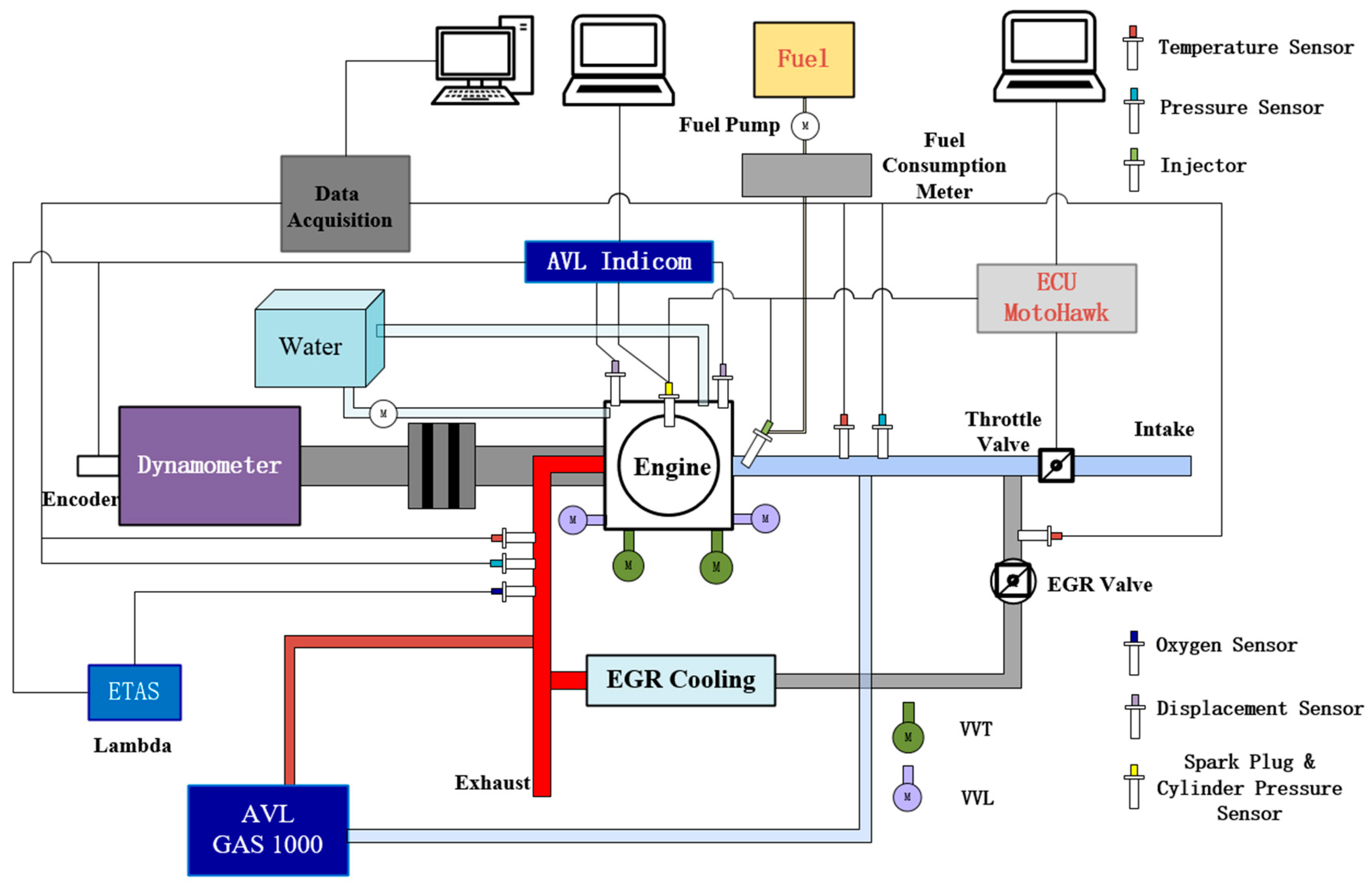
2.1. Experimental Setup

The single cylinder inlet injection engine used in this paper was modified from a single-cylinder diesel engine [19,20]. The intake and exhaust variable valve timing (VVT) mechanism was added to form a single-cylinder gasoline engine with continuously VVT and variable valve timing lift (VVL). The specific engine parameters are shown in Table 1.
The VVT and VVL were controlled with stepping motors, and the control unit of the stepping motors was an stm32 microcontroller. The valve lift was measured with the displacement sensors and then recorded and outputted using an AVL Indicom combustion analyzer. The cylinder pressure data of 200 cycles was measured using the Kistler 6115B and then collected and calculated using the AVL Indicom. The main test equipment is shown in Table 2, and the overall schematic diagram of the experimental platform is shown in Figure 2.
During the experiment, the engine speed was 1000 r/min, the throttle was kept fully open, the intake temperature was 30 °C, the water temperature was 90 °C, the intake pressure was atmospheric pressure, and the gasoline injection pressure was 4.0 bar. It was found that the lowest cyclic variation in HCCI in the test was at lambda = 1.05, so the lambda in this paper was controlled to be 1.05. The fuel used for the experiment was RON92 gasoline. During the test, the intake valve profile and phase and the maximum lift of the exhaust valve remained unchanged, and the engine load was controlled by changing the exhaust valve closing (EVC) timing to control the amount of fresh mixture and residual exhaust gas in the cylinder. The specific valve control parameters are shown in Table 3. The amount of external EGR was controlled with the electronically controlled EGR valve, and the external EGR rate was determined by measuring the intake and exhaust carbon dioxide volume fractions with the AVL emission meter.
Measurement errors and uncertainties because of the instruments, methods, and measurements must be taken into consideration. As shown in Equation (1), the overall uncertainty ( U ) was calculated according to the literature [21,22]. The uncertainties of the equipment were U 1 , U 2 , U 3 , U n , and the U was calculated to be ±2.88%, which was lower than 5% and met the engineering specifications [23].
U = U 1 2 + U 2 2 + U 3 2 + + U n 2

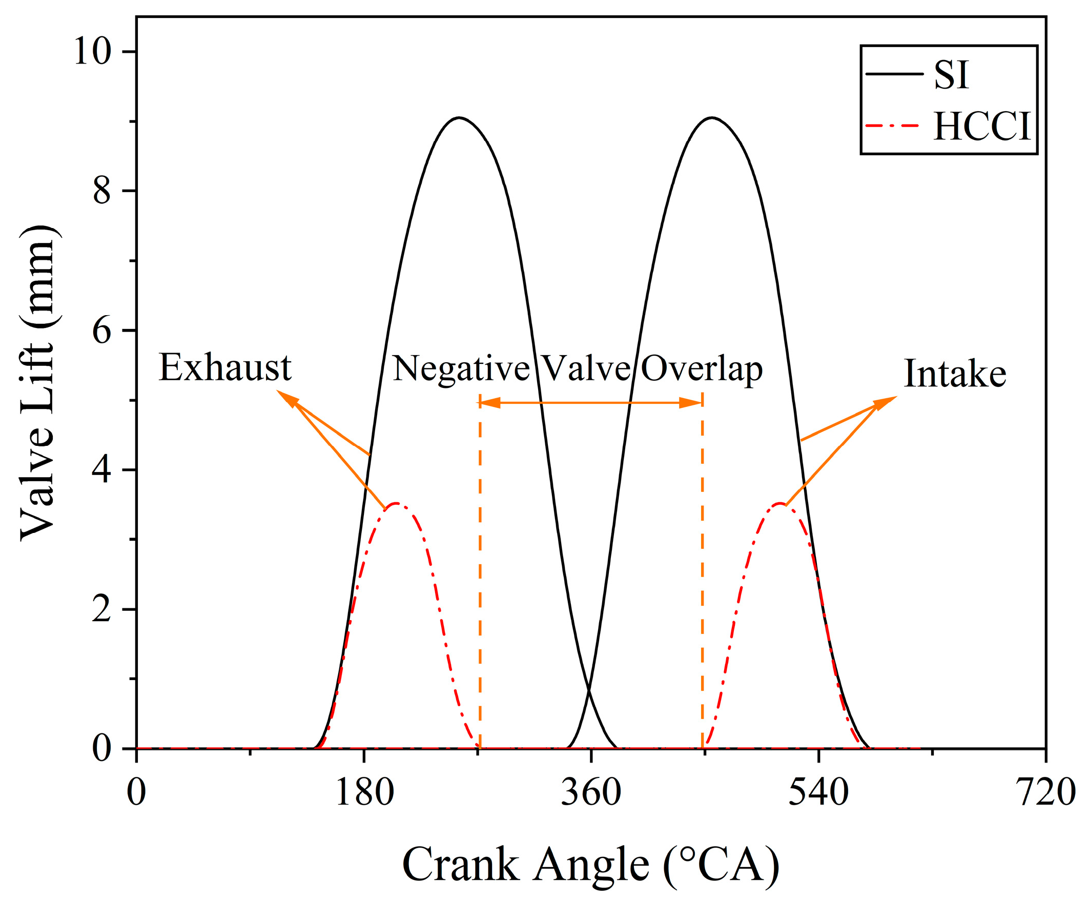
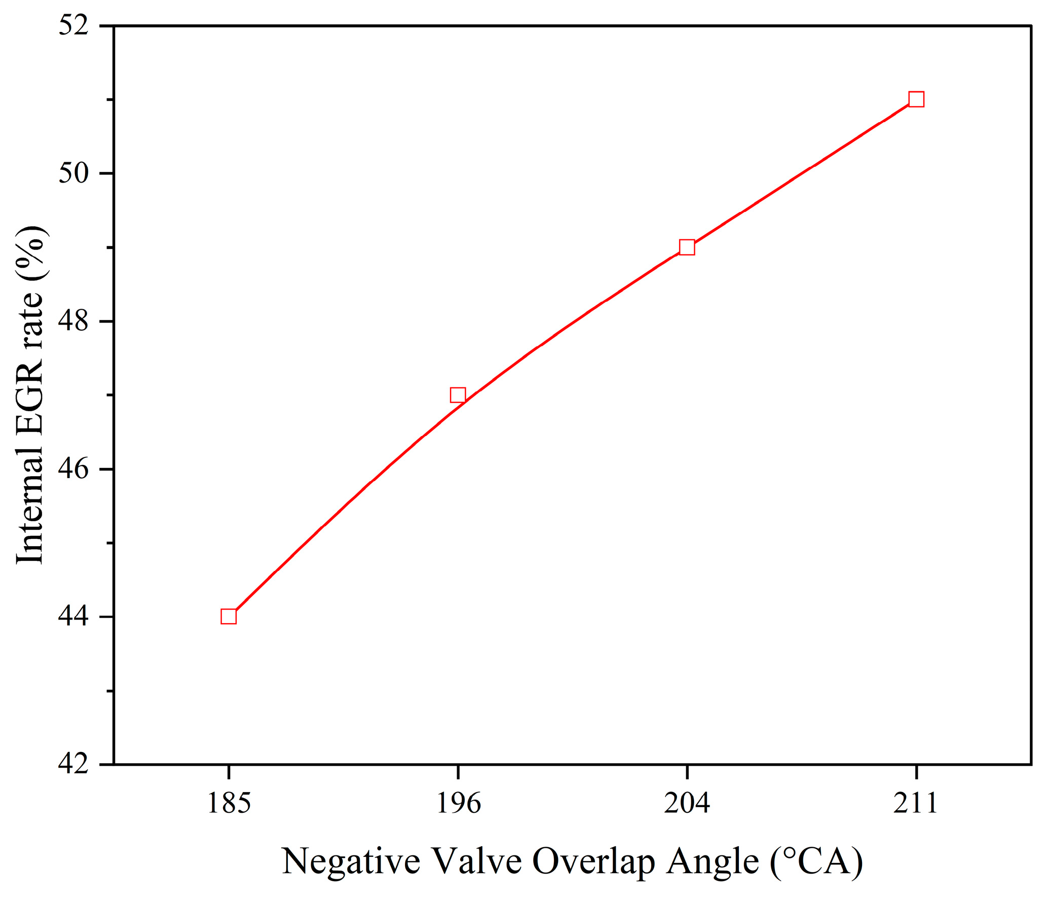
2.2. Internal EGR Rate Estimation

In the study of internal EGR-type HCCI combustion, the internal EGR rate ( EGR i n t ) needs to be estimated. Referring to the literature [24], the estimation process is as follows:
m tot = m fuel   + m air   + m EGR   + m res  
EGR i n t = m res   m tot  
T = P V m R
m res = m EVC = P EVC V EVC R T EVC
The mass of the total species in the cylinder is m tot   , m fuel   represents the fuel mass, m air   is the fresh air mass, m EGR   indicates the external EGR mass, and m res   denotes the residual exhaust gas mass. The average in-cylinder temperature ( T ) is calculated from the gas equation of state. P and V denote the cylinder pressure and cylinder volume, respectively, and R is the gas constant. P EVC , T EVC , and V EVC are the in-cylinder pressure, temperature, and cylinder volume, respectively, at the timing of exhaust valve closure. Because T EVC is difficult to measure, according to the literature, this paper adopts the exhaust gas temperature ( T EXH ) to replace it. Then, the residual mass of the exhaust gas in the cylinder is expressed as:
m res = P EVC V EVC R T EXH

2.3. External EGR Rate Estimation

In this paper, the external EGR rate ( EGR ext ) is defined as the ratio of the volume fraction of intake CO2 to the volume fraction of exhaust CO2 and is calculated as follows [25]:
EGR ext   = ( % C O 2 ) i n t a k e ( % C O 2 ) e x h a u s t × 100
where ( % C O 2 ) i n t a k e is the volume fraction of CO2 in the intake port and ( % C O 2 ) e x h a u s t is the volume fraction of CO2 in the exhaust.

2.4. Calculation of Heat Release Rate

Cylinder pressure data for 200 consecutive engine cycles were recorded with a 0.5 °CA interval at each engine operating point. The heat release rate (HRR) was calculated according to the first law of thermodynamics; CA10, 50, and 90 were defined as the crank angles at which the fuel burns 10%, 50%, and 90%, respectively; and the combustion duration was expressed as CA10-CA90. The heat release rate was calculated as follows [26] (Equations (9) and (10) are empirical formulas and provided by the AVL combustion analysis manual.):
H R R = k k 1 × P × d V d θ + 1 k 1 × V × d P d θ
k = 0.2888 C v θ + 1
C v θ = 0.7 + T θ × 0.155 + 0.1 × 10 3
where k is the polytropic coefficient, θ is the crank angle, and C v θ represents the constant volume specific heat.

3. Results and Discussion

The EVC timings were first scanned to obtain a set of HCCI operation condition points, and then coupled internal and external EGR control was performed to analyze the effect of internal and external EGR on HCCI combustion.

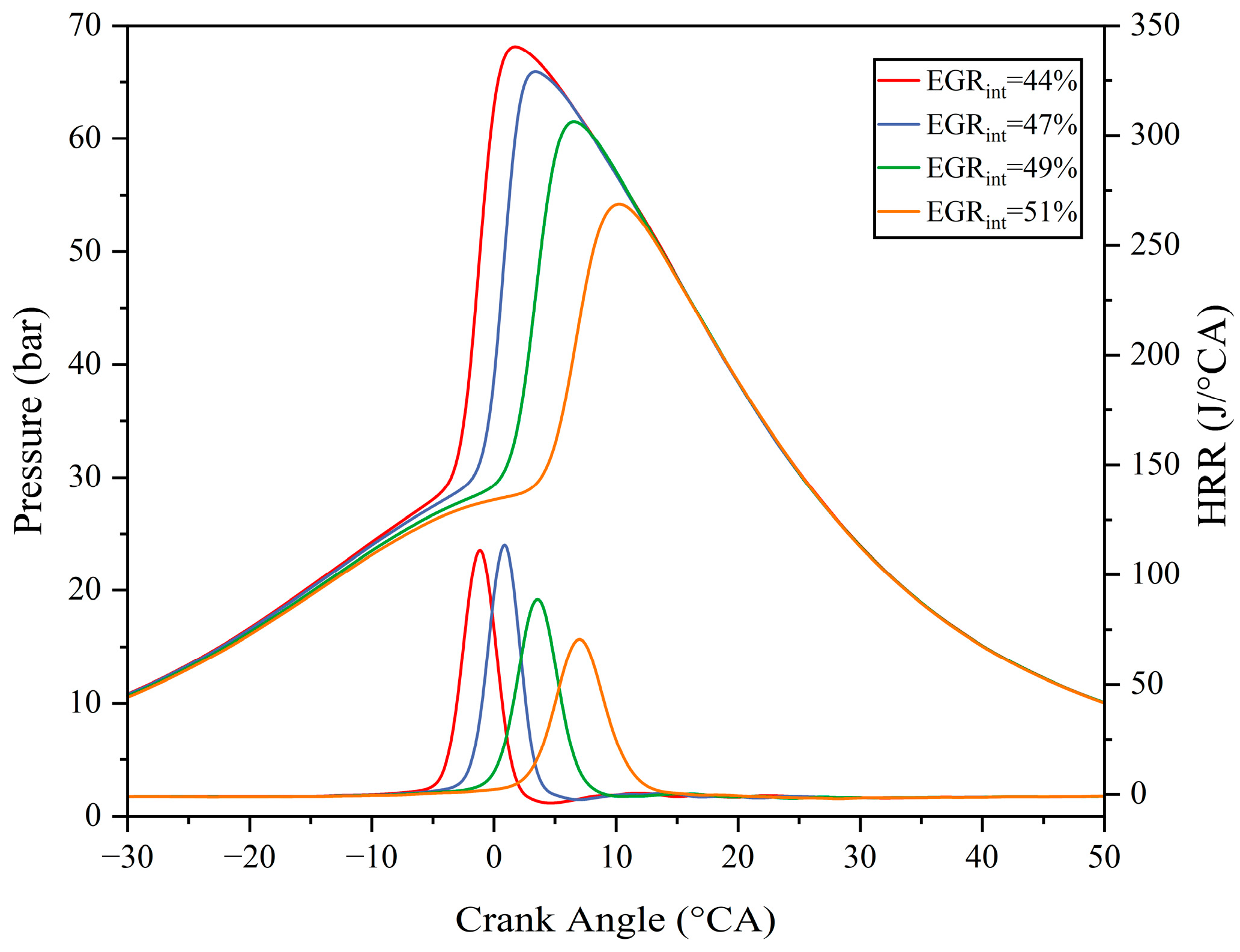
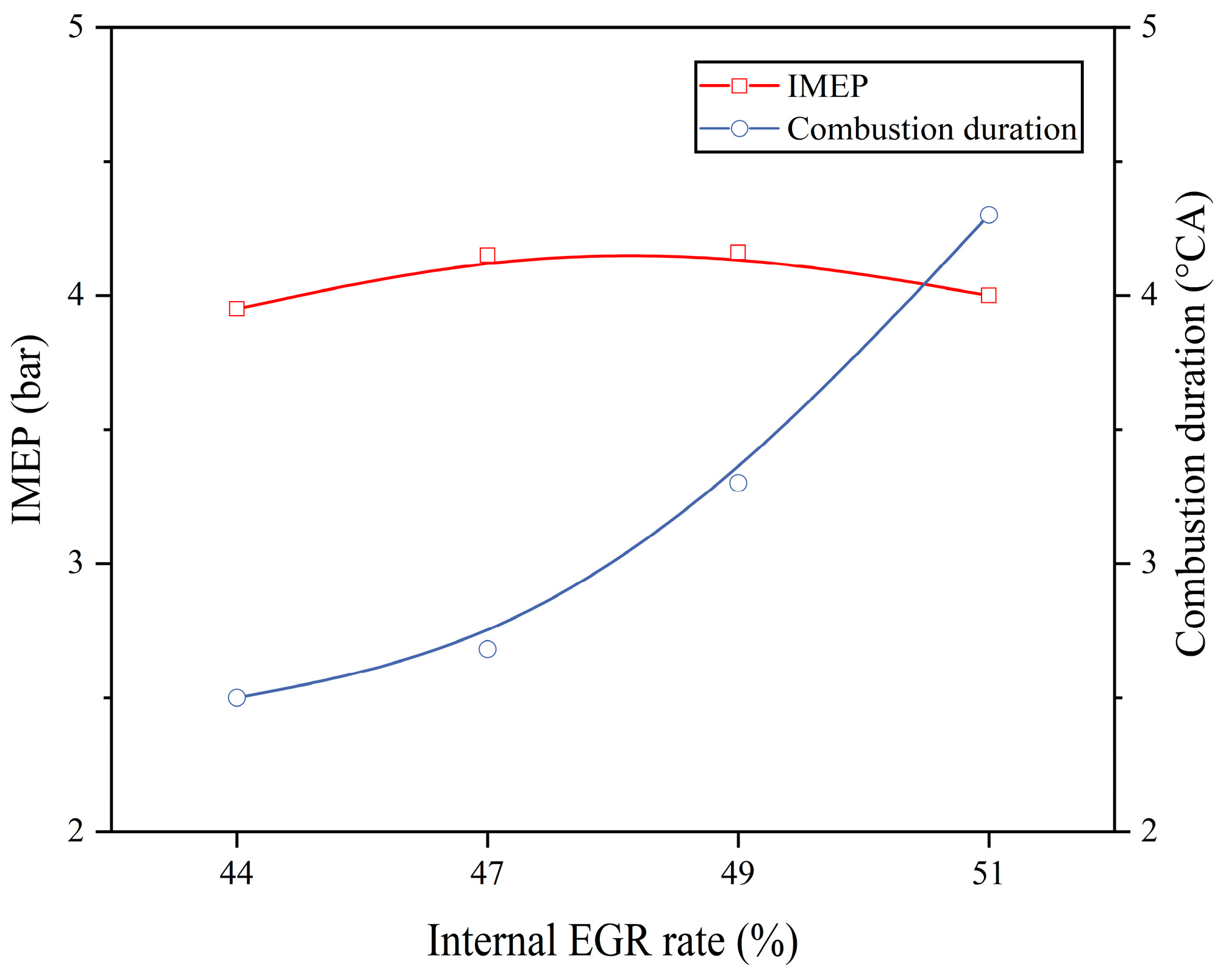
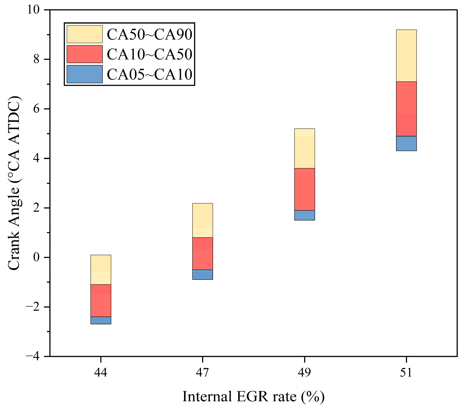
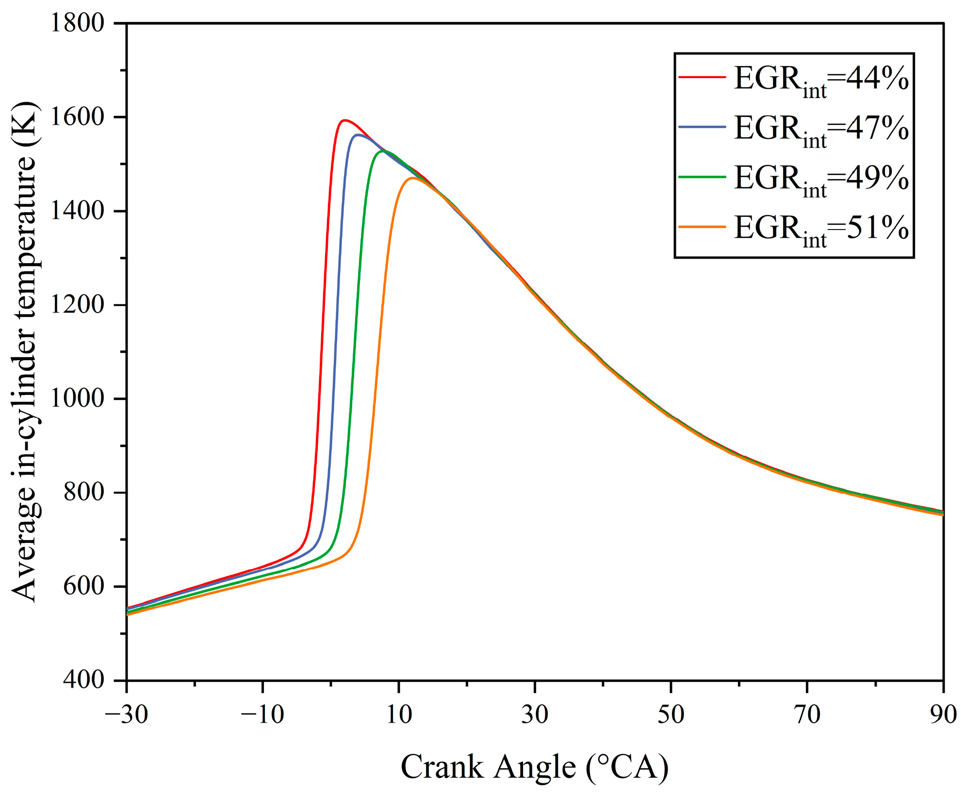
3.1. Effect of Internal EGR on HCCI Combustion and Emissions

The intake valve profile and phase were kept constant and the NVO gradually increased, with the exhaust valve closing early. According to Figure 3, the internal EGR rate expanded from 44% to 51% when the NVO was raised from 185 °CA (EVC = 278 °CA ATDC) to 211 °CA.
As shown in Figure 4 and Figure 5, with the increase in the internal EGR rate, the cylinder pressure peak and the heat release rate peak gradually declined, the exothermic start point was gradually delayed, and the pressure rise rate (PRR) peak was between about 10 and 25 bar/°CA, which belongs to the HCCI detonation combustion boundary operating condition points. A set of HCCI detonation operating condition points was obtained by changing the EVC timing as the reference point for adding external EGR.
In Figure 6, as the internal EGR rate rises, the IMEP shows a pattern of increasing and then decreasing. The combustion duration, although gradually increasing, is still relatively short compared with the spark ignition combustion, which indicates that the HCCI burns faster at a high load. The shorter combustion duration of the internal EGR-type HCCI was also confirmed in the literature [15].
At this point, combined with Figure 7, it can be seen that as the internal EGR rate becomes lower, the combustion phase is more advanced, the compression work is more negative, and the CA90 is close to the upper compression stop at an internal EGR rate of 44%. Therefore, although the lower internal EGR rate increases the unburnt mixture in the cylinder, more negative compression work causes the IMEP to appear to increase and then decrease slightly with the lower EGR rate.
As shown in Figure 8, with the increase in the internal EGR rate, the NOX emission gradually drops from 8.7 g/kW·h to 1.1 g/kW·h. The CO and HC emissions can be approximated as a gradual incremental increase, and at the internal EGR rate of 51%, the two of them are 12 g/kW·h and 4.7 g/kW·h, respectively. The average in-cylinder temperature has a relatively large influence on the emission products; as shown in Figure 9, the average temperature of the cylinder gradually decreases as the increase in the internal EGR rate gradually decreases. The above performance is mainly due to the fact that when the internal EGR rate is higher, the amount of residual exhaust gas in the cylinder is higher and the combustion temperature in the cylinder decreases, which leads to a decrease in the generation of NOX; but due to the lower combustion temperature, which results in an increase in the phenomenon of incomplete combustion. There is a gradual increase in the generation of the intermediate products HC and CO.

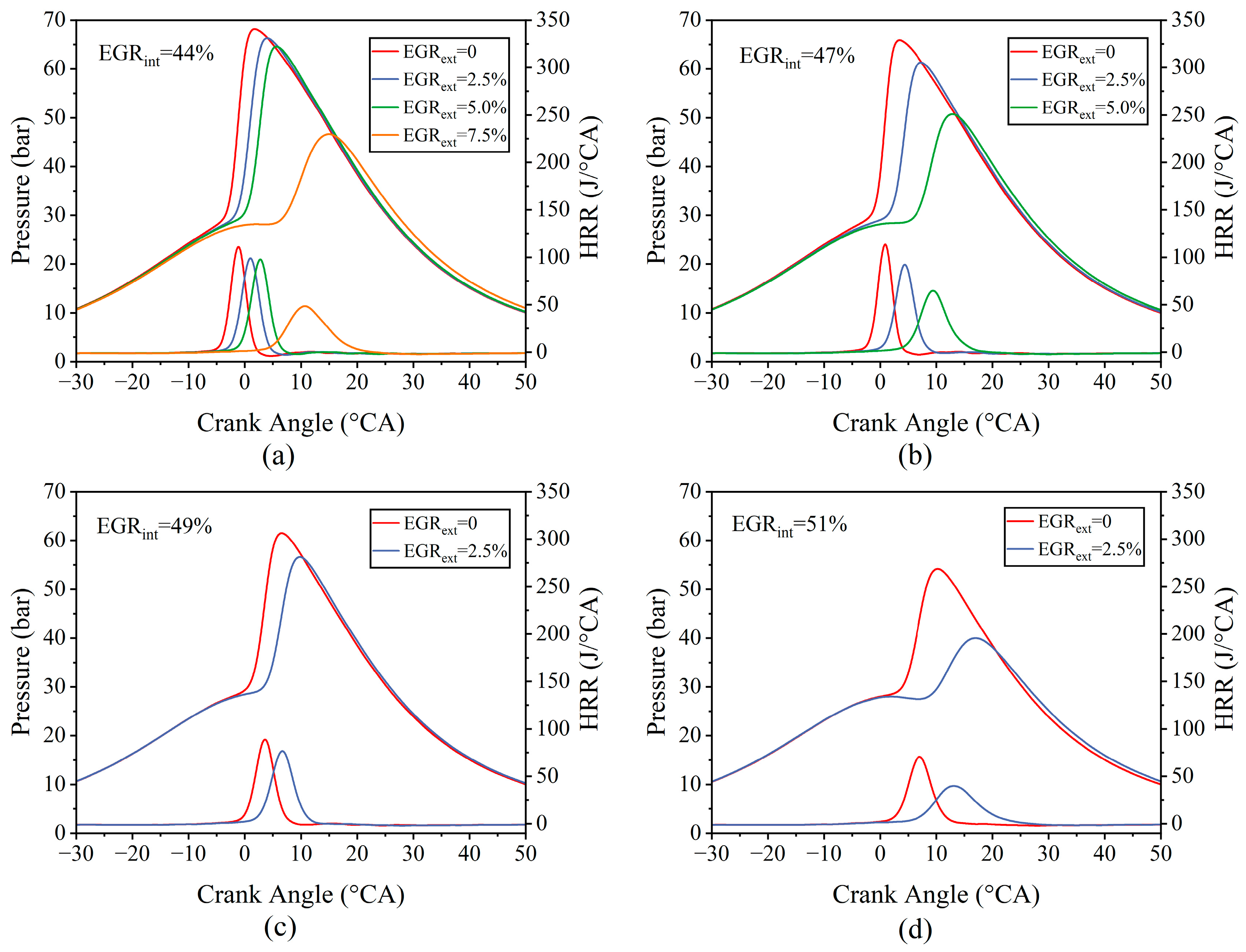
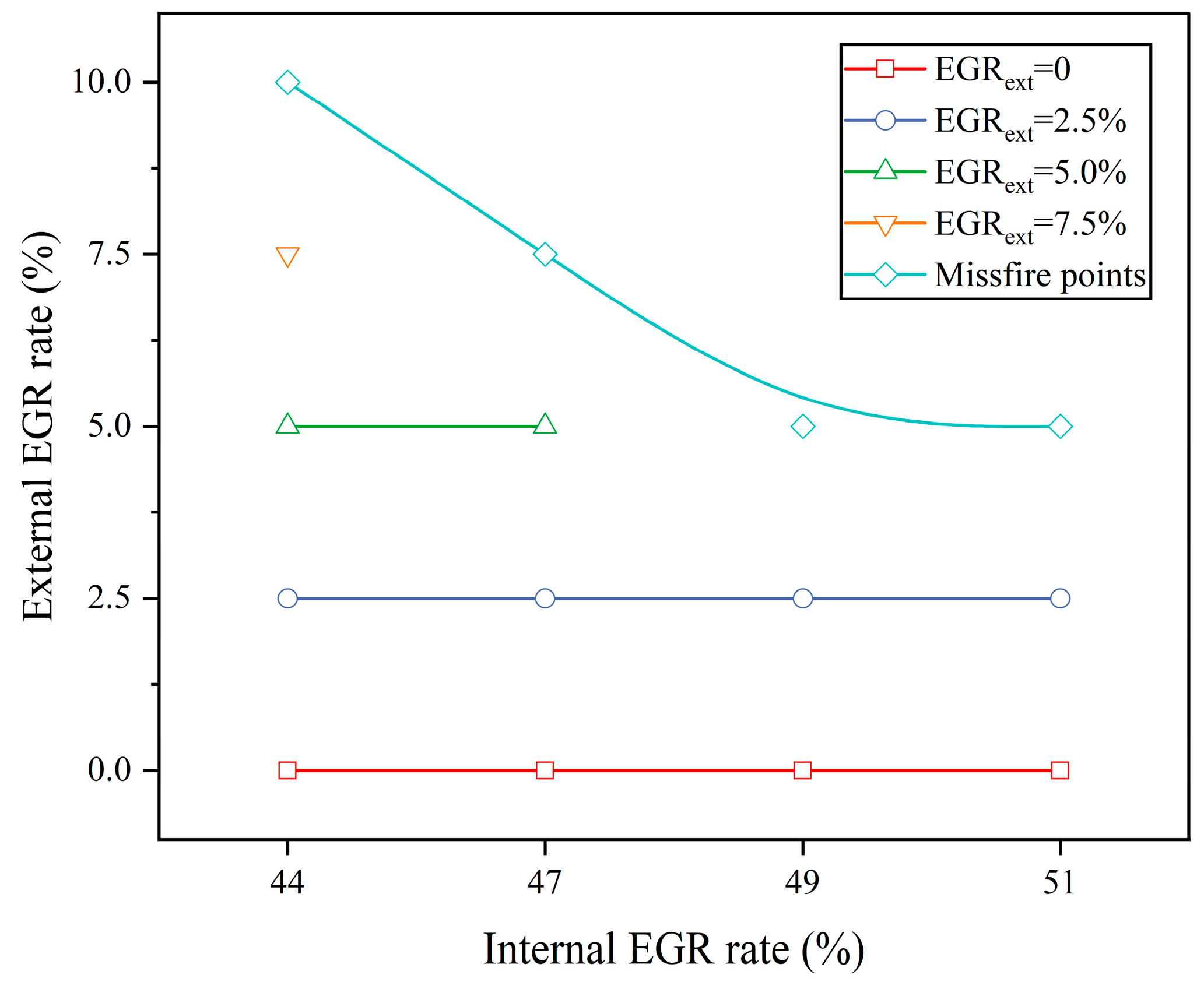
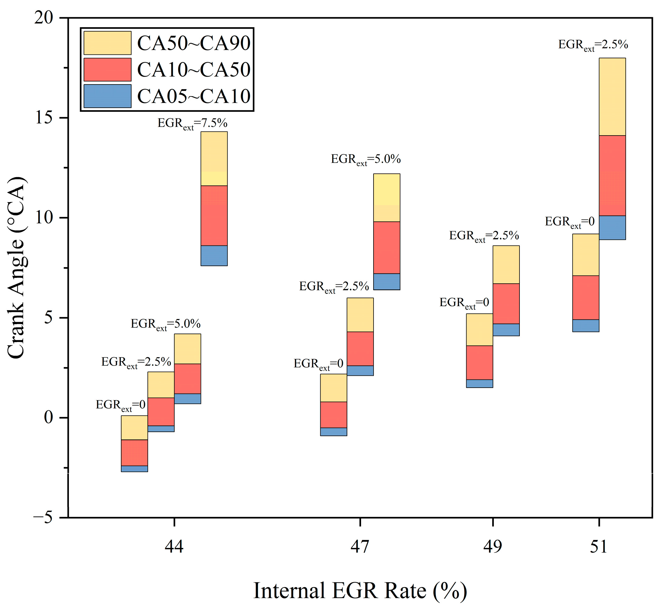
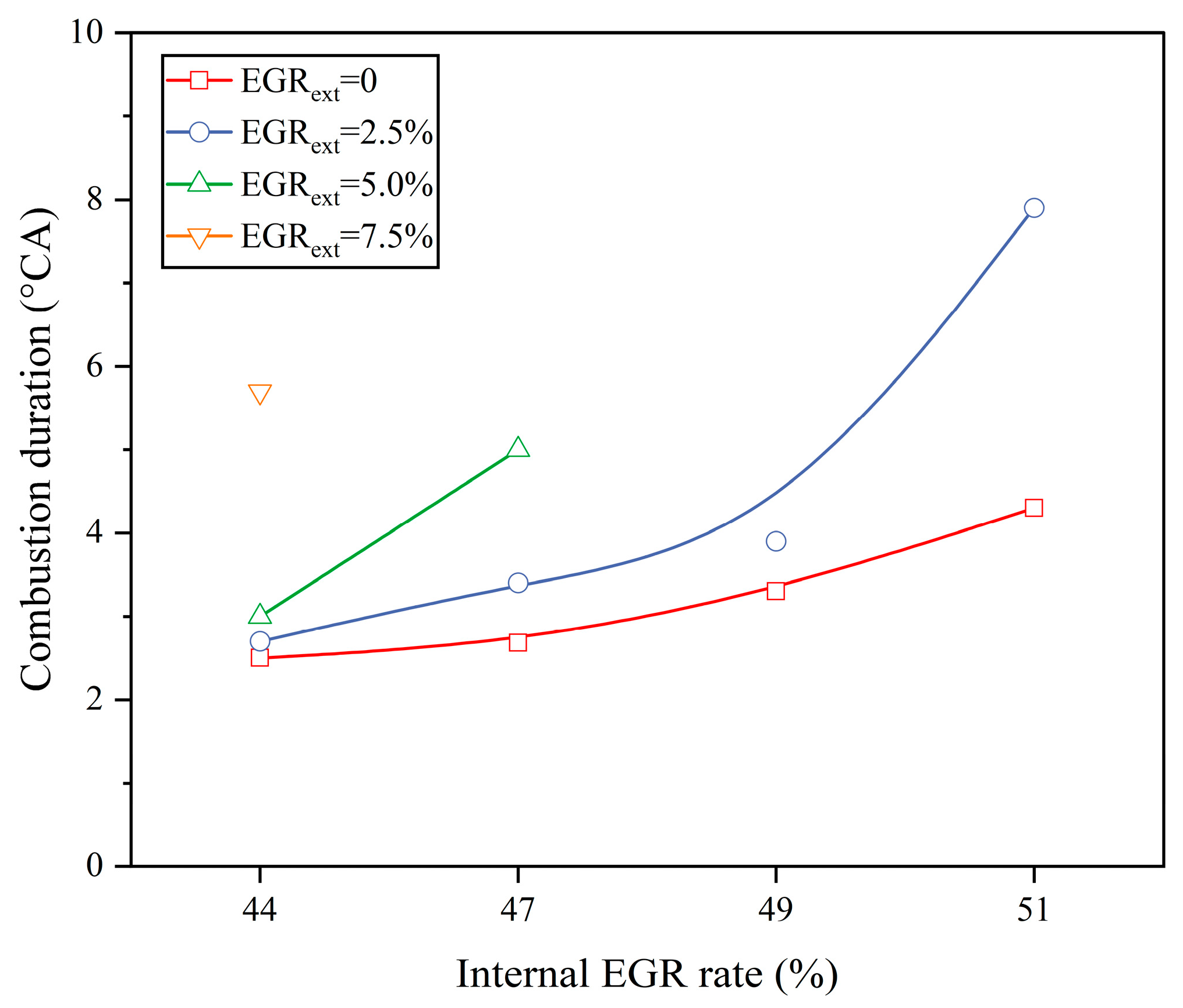
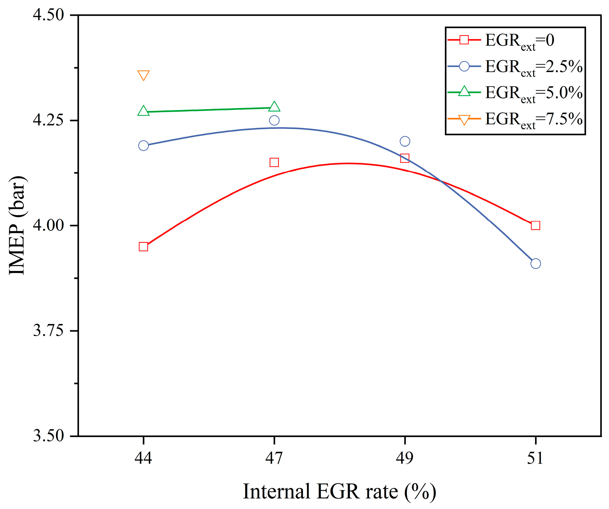
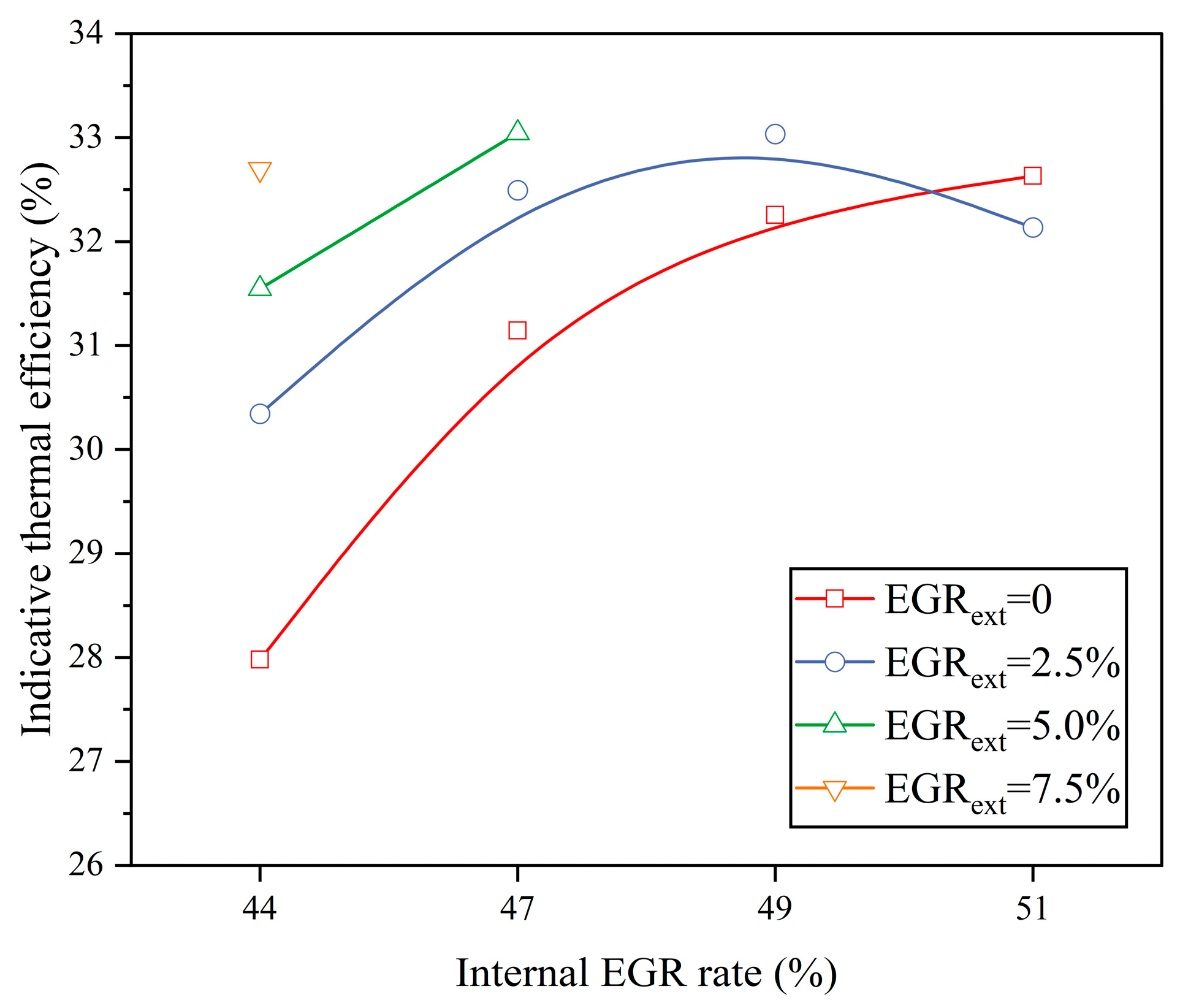
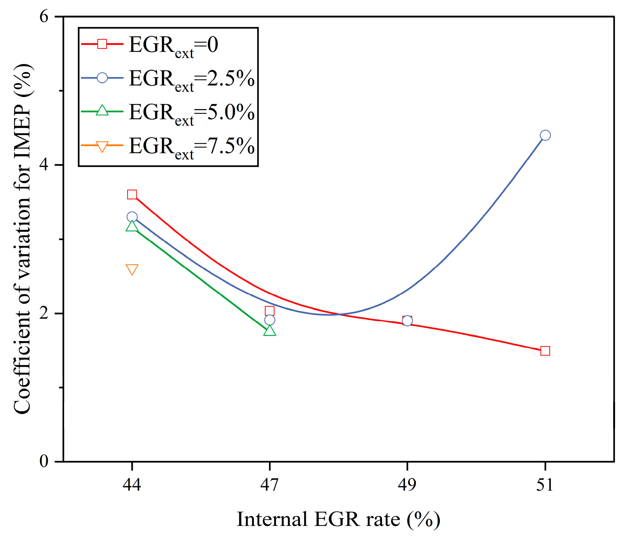
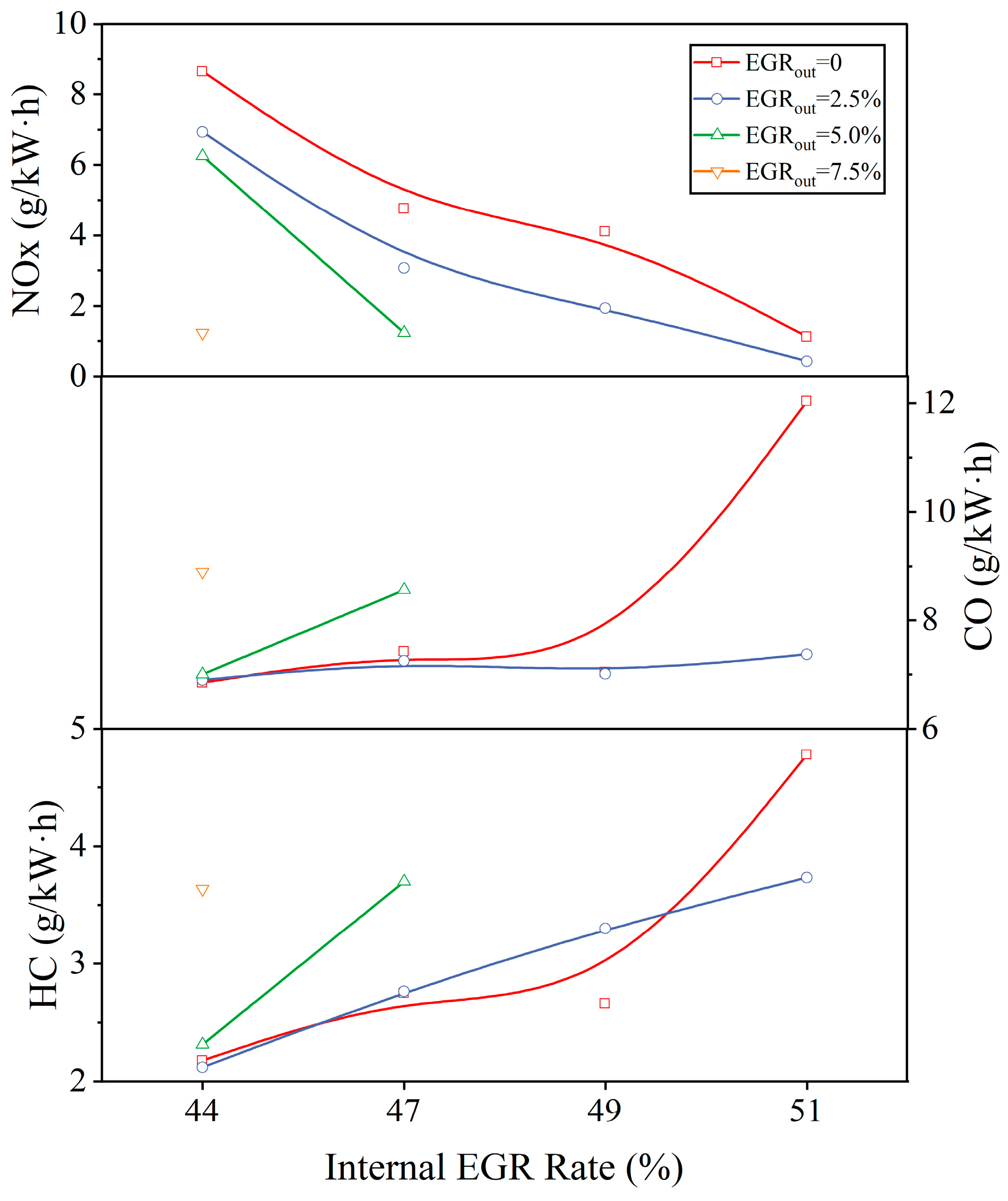
3.2. Effects of Internal and External EGR Coupling on HCCI Combustion and Emissions

Based on the previous data, the engine works roughly when the internal EGR rate is low. On the one hand, this is due to the lower amount of residual exhaust gas in the cylinder and the higher amount of fresh mixture; on the other hand, due to the simultaneous spontaneous combustion of multiple points in the cylinder near the compression top stop under the action of pressure and temperature, the combustion speed is much higher than that of the traditional SI combustion, which leads to the high pressure rise rate. External EGR is a technology that converts high-temperature exhaust gas into low-temperature exhaust gas after cooling by the intercooling system.
External EGR has an inhibitory effect on engine combustion and helps to inhibit the burst combustion at large HCCI loads, thus further expanding the upper load limit of HCCI, but too much external EGR can lead to engine misfire. Therefore, different proportions of external EGR are introduced until misfire occurs for the benchmark points of different internal EGR rates (internal EGR rates of 44%, 47%, 49%, and 51%, respectively) described in the previous section, to obtain the range of tolerable external EGR rates for different internal EGR benchmark operating conditions and to further explore the potential of load expansion under different NVO angles.
The addition of external EGR causes combustion to lag. As shown in Figure 10, Figure 11 and Figure 12, at the fixed benchmark operating point, the cylinder pressure peak, PRR peak, HRR peak, and average in-cylinder temperature decreased as the external EGR rate increased. The cylinder pressure peak dropped from 68.2, 66.2, 61.6, and 54.4 bar to 46.7, 50.9, 56.8, and 40.1 bar, respectively, and the peak pressure rise rate declined from 23.4, 19.5, 15.1, and 9.3 bar/°CA to 6.4, 7.6, 10.9, and 3.5 bar/°CA, respectively, at the four benchmark points.
Figure 13 demonstrates the range of external EGR rates that can be tolerated at the four baseline operating points. The maximum external EGR rates for the four baseline operating points under non-misfire conditions are 7.5%, 5%, 2.5%, and 2.5%, respectively, and the ability to tolerate external EGR diminishes as the internal EGR rate climbs. At lower internal EGR rates, the combustion is rougher and can tolerate a larger proportion of external EGR; as the internal EGR rate increases, the roughness of the combustion decays, resulting in a weakened ability to tolerate low-temperature EGR, which also indicates that the HCCI load expansion under the condition of internal and external EGR coupling should be explored toward the side of a smaller NVO angle.
In Figure 14, the external EGR retards engine combustion, with the combustion phase being progressively delayed as the external EGR rate increases. It is worth noting that the ability of the external EGR rate to change the combustion phase increases significantly beyond a certain percentage, with the latest combustion phase at the three benchmark operating points producing a particularly significant lag compared with when there was no external EGR, and the exception of the benchmark point with an internal EGR rate of 49 percent. The reason for this may be due to the fact that no additional test points were set between 2.5% and 5.0% for the external EGR rate in this paper.
As shown in Figure 15, the combustion duration is insensitive to a small percentage of external EGR when the internal EGR rate is low, whereas there is a significant increase in the sensitivity of the combustion duration to a small percentage of external EGR after an increase in internal EGR. At EGRint = 44%, the combustion duration is extended to a maximum of 5.7 °CA, while at an internal EGR of 51%, the combustion duration can be extended to a maximum of 8 °CA. External EGR can extend the combustion duration of the HCCI to only a certain extent, but it cannot completely control it.
In Figure 16, at the same internal EGR rate reference point, the in-cylinder fresh mixture gradually decreases as the external EGR rate increases because the valve phase remains constant. At an internal EGR rate of 51%, the addition of external EGR results in a 0.7% reduction in fuel consumption while the IMEP is reduced by 2%, but the pressure rise rate is significantly controlled. After that, as the internal EGR rate decreases, the fuel consumption decreases while the IMEP increases, and at an internal EGR rate of 44%, the fuel consumption decreases by about 6% while the IMEP instead increases by about 10%, from 3.95 bar to 4.38 bar, which proves that the addition of the external EGR does not improve the fuel economy at the higher internal EGR operating points, but it can alleviate combustion. This proves that adding external EGR cannot improve fuel economy at higher internal EGR operating points but it can alleviate the roughness of combustion, and at lower internal EGR operating points it can both improve fuel economy and reduce the roughness of combustion at the same time. Figure 17 shows the corresponding indicative thermal efficiency (ITE) data. The variation rule of the indicative thermal efficiency is basically the same as that of IMEP, except that when the EGRint = 51%, the ITE is improved after adding external EGR in other baseline points. The ITE of the maximum external EGR rate increases and then decreases with the increase in the internal EGR rate, with a peak value of 33.05% (EGRint = 47% and EGRext = 5%), which indicates that the external EGR can improve the economy of the HCCI at large loads.
In Figure 18, the coefficient of variation for IMEP (COVIMEP) decreases gradually from 3.6% to 1.49% with the increase in the internal EGR, which means that the increase in the internal EGR can improve the COVIMEP while suppressing rough combustion. At the same internal EGR rate, external EGR decreases the COVIMEP first, and a continuous increase in the external EGR leads to engine misfire and increased COVIMEP. Because various internal EGR rates have different tolerances to external EGR, the improvement in the COVIMEP with external EGR declines as the internal EGR rate climbs. At EGRint = 51%, the addition of 2.5% external EGR causes the COVIMEP to jump from 1.49% to 4.4%.
According to Figure 19, it can be seen that with the increase in the external EGR rate, the NOX emission shows an overall decreasing trend, which is mainly due to the fact that NOX is greatly affected by the in-cylinder combustion temperature. When the external EGR rate is lower, the amount of fresh mixture is larger and the maximum in-cylinder combustion temperature is higher, which creates a better condition for the formation of NOX; the in-cylinder temperature decreases after the addition of the external EGR, which suppresses the generation of NOX. Except for the benchmark operating point where the internal EGR rate is 51%, the HC and CO of the other three benchmark operating points do not change significantly under the condition of a small percentage of external EGR, and the HC and CO emissions show a tendency to increase after the external EGR rate reaches 5%. For the benchmark operating point with an internal EGR rate of 51%, according to the previous section, the fuel consumption basically remains unchanged and the IMEP decreases after adding 2.5% external EGR. In Figure 11, the maximum average in-cylinder temperature of this operating point is less than 1400 K, which is not conducive to the complete combustion of the combustible mixture, and a small portion of the combustible mixture might not produce incomplete combustion to be discharged in the unburned form, resulting in a decrease in HC and CO emissions.

4. Conclusions

In this paper, the EVC timings were scanned to obtain a set of HCCI baseline operating points, and then the internal and external EGR coupling control was performed to draw the following conclusions:
External EGR delays HCCI ignition timing and slows the combustion speed. As the internal EGR rate rises, which means that the HCCI burns less roughly, the maximum external EGR ratio that can be tolerated decreases. When the internal EGR rate climbs from 44% to 51%, the maximum external EGR rate that can form stable combustion drops from 7.5% to 2.5%.
The effect of external EGR is more obvious for the HCCI detonation operating point when the internal EGR rate is small. For the HCCI detonation operating point where the pressure rise rate peak is in the range of 15~25 bar/°CA, the addition of no more than 10% of external EGR can control the pressure rise rate peak to less than 10 bar/°CA, which reduces the fuel consumption and increases the IMEP, so the coupling control of internal and external EGR should be explored in the direction of a smaller NVO angle. Coupled internal and external EGR control improves the indicated thermal efficiency of HCCI at high pressure rise rates.
The effect of external EGR on the HCCI burst condition point with a large internal EGR rate is mainly reflected in the control of the pressure rise rate. For the HCCI operating point where the internal EGR rate is greater than 50%, the addition of a small percentage of external EGR can further control the HCCI pressure rise to below 5 bar/°CA, but the IMEP will not increase significantly.
A reduced internal EGR rate helps to reduce COVIMEP, and a smaller internal EGR rate combined with an appropriate external EGR rate reduces COVIMEP, but a larger internal EGR rate combined with a small amount of external EGR results in increased COVIMEP.
NOx emissions decrease significantly with increasing external EGR rates, and CO and HC emissions increase slightly with increasing external EGR rates prior to engine misfire.

Author Contributions

Formal analysis, R.Z.; Investigation, H.T.; Resources, J.W.; Writing—original draft, F.W. and Y.W.; Writing—review & editing, Y.S. All authors have read and agreed to the published version of the manuscript.

Funding

This work was supported by the National Energy R&D Center of Petroleum Refining Technology (RIPP, SINOPEC, grant number 33600000-22-ZC0607-0003), the National Natural Science Foundation of China (grant number U21A20166).

Data Availability Statement

The data presented in this study are available on request from the corresponding author.

Conflicts of Interest

Authors Huayu Tian, Jun Wang and Ran Zhang were employed by the company Sinopec Research Institute of Petroleum Processing. The remaining authors declare that the research was conducted in the absence of any commercial or financial relationships that could be construed as a potential conflict of interest.

References

  1. Joshi, A. Review of Vehicle Engine Efficiency and Emissions. SAE Int. J. Adv. Curr. Pract. Mobil. 2022, 4, 1704–1733. [Google Scholar] [CrossRef]
  2. Zhao, W.; Wu, H.; Mi, S.; Zhang, Y.; He, Z.; Qian, Y.; Lu, X. Experimental investigation of the control strategy of high load extension under iso-butanol/biodiesel dual-fuel intelligent charge compression ignition (ICCI) mode. Renew. Sustain. Energy Rev. 2023, 172. [Google Scholar] [CrossRef]
  3. Lyu, M.; Bao, X.; Zhu, R.; Matthews, R. State-of-the-art outlook for light-duty vehicle emission control standards and technologies in China. Clean Technol. Environ. Policy 2020, 22, 757–771. [Google Scholar] [CrossRef]
  4. Duan, X.; Lai, M.-C.; Jansons, M.; Guo, G.; Liu, J. A review of controlling strategies of the ignition timing and combustion phase in homogeneous charge compression ignition (HCCI) engine. Fuel 2020, 285, 119142. [Google Scholar] [CrossRef]
  5. Noguchi, M.; Tanaka, Y.; Tanaka, T.; Takeuchi, Y. A Study on Gasoline Engine Combustion by Observation of Intermediate Reactive Products during Combustion. In Proceedings of the SAE International Off-Highway and Powerplant Congress and Exposition; Available online: https://saemobilus.sae.org/content/790840/ (accessed on 10 November 2023).
  6. Onishi, S.; Jo, S.H.; Shoda, K.; Jo, P.D.; Kato, S. Active Thermo-Atmosphere Combustion (ATAC)—A New Combustion Process for Internal Combustion Engines; SAE International: Warrendale, PA, USA, 1979. [Google Scholar]
  7. Waqas, M.U.; Hoth, A.; Kolodziej, C.P.; Rockstroh, T.; Gonzalez, J.P.; Johansson, B. Detection of low Temperature heat release (LTHR) in the standard Cooperative Fuel Research (CFR) engine in both SI and HCCI combustion modes. Fuel 2019, 256, 115745. [Google Scholar] [CrossRef]
  8. Calam, A.; Aydoğan, B.; Halis, S. The comparison of combustion, engine performance and emission characteristics of ethanol, methanol, fusel oil, butanol, isopropanol and naphtha with n-heptane blends on HCCI engine. Fuel 2020, 266, 117071. [Google Scholar] [CrossRef]
  9. Liu, Y.; Li, L.; Lu, H.; Schmitt, S.; Deng, J.; Rao, L. SI/HCCI Mode Switching Optimization in a Gasoline Direct Injection Engine Employing Dual Univalve System. J. Eng. Gas Turbines Power 2019, 141, 031001. [Google Scholar] [CrossRef]
  10. Li, J.; Zhao, H.; Ladommatos, N.; Ma, T. Research and Development of Controlled Auto-Ignition (CAI) Combustion in a 4-Stroke Multi-Cylinder Gasoline Engine. SAE International Fall Fuels & Lubricants Meeting & Exhibition. 2001. Available online: https://saemobilus.sae.org/content/2001-01-3608 (accessed on 10 November 2023).
  11. Nier, T.; Kulzer, A.; Karrelmeyer, R. Analysis of the Combustion Mode Switch between SI and Gasoline HCCI. In Proceedings of the SAE 2012 World Congress & Exhibition; 2012. Available online: https://saemobilus.sae.org/content/2012-01-1105/ (accessed on 10 November 2023).
  12. Manofsky, L.; Vavra, J.; Assanis, D.N.; Babajimopoulos, A. Bridging the Gap between HCCI and SI: Spark-Assisted Compression Ignition. SAE 2011 World Congress & Exhibition. 2011. Available online: https://saemobilus.sae.org/content/2011-01-1179/ (accessed on 10 November 2023).
  13. Li, L.; Xie, H.; Chen, T.; Yu, W.; Zhao, H. Experimental Study on Spark Assisted Compression Ignition (SACI) Combustion with Positive Valve Overlap in a HCCI Gasoline Engine. SAE 2012 World Congress & Exhibition. 2012. Available online: https://saemobilus.sae.org/content/2012-01-1126/ (accessed on 10 November 2023).
  14. Kulzer, A.; Nier, T.; Karrelmeyer, R. A Thermodynamic Study on Boosted HCCI: Experimental Results. SAE 2011 World Congress & Exhibition. 2011. Available online: https://saemobilus.sae.org/content/2011-01-0905/ (accessed on 10 November 2023).
  15. Cairns, A.; Blaxill, H. The Effects of Combined Internal and External Exhaust Gas Recirculation on Gasoline Controlled Auto-Ignition. SAE 2005 World Congress & Exhibition. 2005. Available online: https://saemobilus.sae.org/content/2005-01-0133/ (accessed on 10 November 2023).
  16. Xie, H.; Chen, T.; Zhang, Y.; Zhao, H. Influence of external EGR on expanding HCCI combustion operation range. Ranshao Kexue Yu Jishu/J. Combust. Sci. Technol. 2008, 14, 491–495. [Google Scholar]
  17. Xu, F.; Wang, Z.; Yang, D.; Wang, J. Potential of High Load Extension for Gasoline HCCI Engine Using Boosting and Exhaust Gas Recirculation. Energy Fuels 2009, 23, 2444–2452. [Google Scholar] [CrossRef]
  18. Xu, F.; Wang, Z.; Yang, D.-B.; Wang, J.-X. External EGR combined with internal EGR for high load extension on a gasoline HCCI engine. Neiranji Gongcheng/Chin. Intern. Combust. Engine Eng. 2010, 31, 6–10. [Google Scholar]
  19. Jin, Z.; Hong, W.; You, T.; Su, Y.; Li, X.; Xie, F. Effect of Multi-Factor Coupling on the Movement Characteristics of the Hydraulic Variable Valve Actuation. Energies 2020, 13, 2870. [Google Scholar] [CrossRef]
  20. Han, L.; Duan, J.; Qian, D.; Gong, Y.; Wang, Y.; Xie, F.; Su, Y. Research on Homogeneous Charge Compression Ignition Combustion of Intake Port Exhaust Gas Recirculation Based on Cam Drive Hydraulic Variable Valve Actuation Mechanism. Energies 2022, 15, 438. [Google Scholar] [CrossRef]
  21. How, H.; Masjuki, H.; Kalam, M.; Teoh, Y. An investigation of the engine performance, emissions and combustion characteristics of coconut biodiesel in a high-pressure common-rail diesel engine. Energy 2014, 69, 749–759. [Google Scholar] [CrossRef]
  22. Duan, X.; Li, Y.; Liu, J.; Guo, G.; Fu, J.; Zhang, Q.; Zhang, S.; Liu, W. Experimental study the effects of various compression ratios and spark timing on performance and emission of a lean-burn heavy-duty spark ignition engine fueled with methane gas and hydrogen blends. Energy 2018, 169, 558–571. [Google Scholar] [CrossRef]
  23. Yu, H.; Su, Y.; Shen, B.; Zhang, Y.; Wang, B.; Zhou, Y. Effect of direct methanol injection based on low-flow injector on knock of gasoline engine under heavy load condition. Fuel 2024, 357, 129899. [Google Scholar] [CrossRef]
  24. Ortiz-Soto, E.A.; Vavra, J.; Babajimopoulos, A. Assessment of Residual Mass Estimation Methods for Cylinder Pressure Heat Release Analysis of HCCI Engines with Negative Valve Overlap. J. Eng. Gas Turbines Power 2012, 134, 082802. [Google Scholar] [CrossRef]
  25. Yıldız, M.; Çeper, B.A. A comparative study on gasoline/diesel-fueled RCCI combustion at different premixed ratios and high-EGR diesel CI combustion in an IC engine under low load conditions. Fuel 2022, 324, 124596. [Google Scholar] [CrossRef]
  26. Sarıkoç, S. Effect of H2 addition to methanol-gasoline blend on an SI engine at various lambda values and engine loads: A case of performance, combustion, and emission characteristics. Fuel 2021, 297, 120732. [Google Scholar] [CrossRef]
Figure 1. Typical valve profiles for SI and HCCI engine.
Energies 17 00175 g001
Figure 2. Schematic diagram of experimental platform.
Energies 17 00175 g002
Figure 3. Internal EGR rates at various negative valve overlap angles.
Energies 17 00175 g003
Figure 4. Cylinder pressure and heat release rate at various internal EGR rates.
Energies 17 00175 g004
Figure 5. Cylinder pressure peak and PRR peak at various internal EGR rates.
Energies 17 00175 g005
Figure 6. The IMEP and combustion duration at various internal EGR rates.
Energies 17 00175 g006
Figure 7. HCCI combustion phase at various internal EGR rates.
Energies 17 00175 g007
Figure 8. Emission levels at various internal EGR rates.
Energies 17 00175 g008
Figure 9. Average in-cylinder temperatures corresponding to various internal EGR rates.
Energies 17 00175 g009
Figure 10. Cylinder pressure and HRR after adding external EGR at four baseline operating points. (a) baseline operating point of EGRint = 44%; (b) baseline operating point of EGRint = 47%; (c) baseline operating point of EGRint = 49%; (d) baseline operating point of EGRint = 51%.
Energies 17 00175 g010
Figure 11. Average in-cylinder temperature after adding external EGR at four baseline operating points. (a) baseline operating point of EGRint = 44%; (b) baseline operating point of EGRint = 47%; (c) baseline operating point of EGRint = 49%; (d) baseline operating point of EGRint = 51%.
Energies 17 00175 g011
Figure 12. Cylinder pressure peak and PRR peak after adding external EGR at the four baseline operating points. (a) cylinder pressure peak; (b) pressure rise rate peak.
Energies 17 00175 g012
Figure 13. The range of external EGR that can be tolerated at the four baseline operating points.
Energies 17 00175 g013
Figure 14. Combustion phases of four baseline operating points after adding external EGR.
Energies 17 00175 g014
Figure 15. Combustion duration of four baseline operating points after adding external EGR.
Energies 17 00175 g015
Figure 16. The IMEP of four baseline operating points after adding external EGR.
Energies 17 00175 g016
Figure 17. The indicative thermal efficiency of four baseline operating points after adding external EGR.
Energies 17 00175 g017
Figure 18. The coefficient of variation for IMEP under four baseline operating points after adding external EGR.
Energies 17 00175 g018
Figure 19. Emission levels of four baseline operating points after adding external EGR.
Energies 17 00175 g019
Table 1. Engine parameters.
Engine PropertiesSpecifications
Engine typeSingle cylinder
Combustion chamber typeω
Bore/Stroke80 mm/80 mm
Displacement0.402 L
Compression ratio15.0:1
Intake valve number1
Exhaust valve number1
Intake valve timing and liftContinuously variable
Exhaust valve timing and liftContinuously variable
Table 2. Experimental equipment.
EquipmentTypeRangeAccuracyUncertainty (±%)
DynamometerCW50Speed 0~6000 r/min≤±1 r/min0.1
Torque 0~200 N·m≤±0.2 N·m1.5
Pressure sensorKistler 6115B0~200 bar≤±0.6 bar0.3
Lambda meterETAS LA40.65~5≤±0.1%1
EncoderKistler 2613B0~720 °CA≤±0.5 °CA0.07
ECUMotoHawk---
Fuel consumption meterONOSOKKI DF24200.2~82 kg/h≤±0.01 g/s0.03
COAVL GAS 10000~10 %vol≤±0.02%1
HCAVL GAS 10000~5000 ppm≤±4 ppm1.3
NOxAVL GAS 10000~4000 ppm≤±25 ppm1.5
Combustion analyzerAVL Indicom---
Table 3. Valve parameters.
ItemParameter
Maximum intake valve lift3.5 mm
Maximum exhaust valve lift5.0 mm
Intake valve opening timing−257 °CA ATDC
Intake valve closing timing−153 °CA ATDC
Exhaust valve opening timing103 °CA ATDC
Exhaust valve closing timingVariable
Disclaimer/Publisher’s Note: The statements, opinions and data contained in all publications are solely those of the individual author(s) and contributor(s) and not of MDPI and/or the editor(s). MDPI and/or the editor(s) disclaim responsibility for any injury to people or property resulting from any ideas, methods, instructions or products referred to in the content.

