Review

Review on Non-Isolated Multiport Converters for Residential DC Microgrids

by
Georgios Salagiannis
* and
Emmanuel Tatakis
Department of Electrical and Computer Engineering, University of Patras, 26504 Rion-Patras, Greece
*
Author to whom correspondence should be addressed.
Energies 2024, 17(1), 222; https://doi.org/10.3390/en17010222
Submission received: 24 November 2023 / Revised: 19 December 2023 / Accepted: 27 December 2023 / Published: 31 December 2023
(This article belongs to the Section F3: Power Electronics)

Abstract

:
Nowadays, energy sustainability needs drive the development of novel power system architectures that efficiently harvest and deliver green energy. Specifically, DC Microgrids (DC-MG) have emerged as promising bases for distributed power generation, especially in residential applications. The pivotal role of power conversion and the need for more affordable and compact converters has led to an increasing research interest. MultiPort Converters (MPCs) exhibit beneficial operational characteristics for these applications and, therefore, a plethora of different topologies is suggested in the literature. Even though there have been some attempts to organize and review the field status, the categorization is based on the existence or not of isolation between the converter’s ports, without providing insight on the topology conception. In this article, a literature review is conducted to specify the most suitable non-isolated MPC topologies for residential DC-MGs. Converters with a power rating ranging from 0.1 to 1 kW are compared based on technical features and categorized according to their topology derivation process. This procedure is performed separately for MPCs suitable for unipolar and bipolar DC Buses. The selected approach highlights the design basis for each MPC in a structured manner, facilitating further development of original converters by both new and experienced researchers.

1. Introduction

Nowadays, climate change and the global energy crisis signify the importance of achieving a higher penetration of Renewable Energy Sources (RESs) in power generation. Furthermore, the fluctuation of their production imposes the inclusion of Energy Storage Systems (ESSs) to aid their operation. Due to the inherent DC nature of most RESs and ESSs, DC-Microgrids (DC-MGs) are becoming promising candidates for their further incorporation [1,2]. In this approach, Distributed Power Generation (DPG) is in the spotlight, supported by the target of achieving Net Zero emissions on a residential, commercial, and industrial level [3]. This article focuses on the former, as it has the potential to become the cornerstone of DPG. In addition, as will be shown below, the current power level of MPCs is relatively low and, therefore, it is well suited for the low power needs of residences.
In the traditional implementation of DC-MGs, each power source or load is connected to the DC Bus via a dedicated Single-Input Single-Output (SISO) DC-DC converter [4]. Therefore, if various RES or ESS units must be integrated in the DC-MG for redundancy or other application-specific reasons, the required hardware is multiplied. Despite its ease of use, this straightforward approach is characterized by higher component count, cost, volume, and maintenance along with demanding communication and coordination between modules [5]. Attempting to address these issues, researchers are exploring the potential use of Multi-Input Multi-Output (MIMO) or MultiPort DC-DC Converters (MPCs). Hence, SISO converter components, which do not operate simultaneously, are integrated to form an MPC. This MPC configuration involves connecting multiple RESs and a single ESS to the DC Bus, as illustrated in Figure 1. In the same figure, the different operating modes of the MPCs, which will be described later, are presented. It is important to acknowledge that MPCs with multiple ESS ports have been documented in the literature [6]. However, their prevalence is limited, and their numbers are insufficient to be incorporated into the scope of this study.
From a converter’s architecture standpoint, MPCs can be classified into three categories based on the presence or absence of isolation between their ports: non-isolated (NI), partially isolated (PI), and isolated (I). Non-isolated MPCs are best suited for small-scale installations where safety standards do not require isolation. These MPCs offer high efficiency and low component count but limited rated power (<1 kW). On the other hand, isolated MPCs, whose ports are all isolated from each other, provide increased rated power (>1 kW). However, this comes at the cost of increased topology complexity and volume, as the converters are usually based on full bridge topologies [7]. Partially isolated MPCs offer a compromise solution, with isolation present between some of the MPC’s ports [8]. In this work, we will focus solely on the topologies of non-isolated MPCs, which are well suited for the small-scale power generation needs of residences [5].
From a system architecture standpoint, MPCs can be designed to operate either in unipolar or bipolar DC-MGs. The architecture of DC-MGs is a current area of research and there is no consensus on whether unipolar or bipolar buses are more suitable for residential applications, as discussed in [4]. Unipolar (UP) buses have been widely studied in the literature due to their simple implementation and control, while bipolar (BP) buses are gaining attention as they offer increased reliability. The two poles of the distribution allow the network to deliver a portion of the nominal power even if one pole goes down because of a fault or a scheduled maintenance [9]. By utilizing relays or switch matrices, it is possible to transfer loads from one pole to another, leading to better management during overload conditions and to increased redundancy for critical loads (e.g., medical). Additionally, when the pole-to-pole voltage of the BP-DC Bus equals the pole-to-ground voltage of the UP-DC Bus (Figure 2), point-of-load converters require half the step-down capability compared to their UP counterparts, leading to increased efficiency and power density. However, the usage of a voltage balancer is unavoidable [10]. This is because load imbalances during normal operation (as the load distribution will not be ideally even), will cause the increase in or reduction of the voltage level of the one pole compared to the other. For the sake of completeness, MPCs designed for both configurations will be examined in this work.
Currently, there are few review papers on UP-ΝΙ-MPCs and especially Three-Port Converters (TPCs). In [1], a great number of TPC topologies for various applications are presented and organized based on their port isolation status, and their basic characteristics are reviewed. The same workflow is followed in [2] to review MPCs with three or more ports. The topologies are divided into combined input/output, reconfigurable, and magnetic/capacitive coupled ports for the NI-MPCs and into two and multiple winding transformer and multiple transformer coupled ports. Wang et al. [5] undertake a thorough classification and evaluation of the NI, PI, and I UP-TPCs in the existing literature. This classification is based on the methodology of deriving these converters from Three-Port System configurations that consist of two-port converters. In these configurations, each port is interconnected with the others through either one (single-stage processing) or two (double-stage processing) SISO power converters. The researchers view MPCs as the result of simplifying the Three-Port system (RES, ESS, Output) by combining some SISO converter parts. Their paper provides insights on UP-TPC modular connection as well as a general method for selecting the most suitable UP-TPC for a specific application. However, there is no converter comparison for high-gain, high-efficiency DC-MG applications, which also holds true for [1,2]. In [11], MPCs undergo classification into distinct categories, taking into consideration their isolation characteristics (NI/PI/I), voltage-boosting capability (high/low), power flow direction (unidirectional/bidirectional), and overall system architecture (modular/non-modular). The comprehensive analysis is supplemented by a literature review on the control methods employed in MPCs. Narayanaswamy and Mandava [12] concentrate their research on NI-MPCs designed for RES integration. Their review commences with a classification of NI-MPCs, aligning them with basic and traditional converters (such as Buck, Boost, Buck-Boost, Cuk, SEPIC, and charge pump). Subsequently, they delve into an analysis of the operating modes. However, their study identifies a limited number of proposed topologies. Due to the broad application scope of their review, these topologies lack the necessary characteristics for seamless integration into DC-MGs. While Lu’s work [13] may not encompass an exhaustive review of multiple Multi-Port Converter (MPC) topologies, it offers valuable insights into design aspects that are often overlooked by researchers. These aspects are categorized into two axes. First, the challenges associated with the high integration of MPCs, including coupled control parameters, constraints on operating modes, and the necessity for sophisticated control and measurement systems, are thoroughly discussed. Second, the paper provides commentary on the reliability of MPCs and their resilience in fault conditions. As it will be shown, the research on BP-NI-MPCs is limited, and, to the best of the authors’ knowledge, there is not any work published thus far summarizing the efforts towards this direction.
It becomes apparent that the increasing research interest on residential DC-MGs and the extensive suggestion of novel MPC topologies requires a summarization of the results presented thus far. Based on the previous paragraph, current review studies either cover a small number of topologies proposed in the literature or categorize MPCs without commenting on the topology conception. This approach proves inadequate when attempting to study MPCs more systematically. The fundamental contribution of this paper is the classification of NI-MPCs for unipolar and bipolar DC-MGs in a manner that highlights the topology derivation process. This will aid new researchers entering the field or engineers working in the industry to catch up with the current research status and propose novel converter topologies, based on the derivation method that best fits their needs. Additionally, the main characteristics of the MPCs suggested in the literature are reviewed and presented coherently. Based on the results of the review process, the current research needs and future research paths are highlighted. The work is organized as follows: Initially, an introduction to the fundamental system operation of NI-MPCs is attempted and the review criteria are established. Subsequently, voltage-boosting capability and efficiency are discussed in more detail due to their high importance. Afterwards, current topologies are classified firstly for UP-DC Buses, based on their derivation method, and a comparative study is conducted. Secondly, current attempts at NI-MPCs for BP-DC Buses are presented and discussed. Finally, the general conclusions are made, and possible future research approaches are proposed.

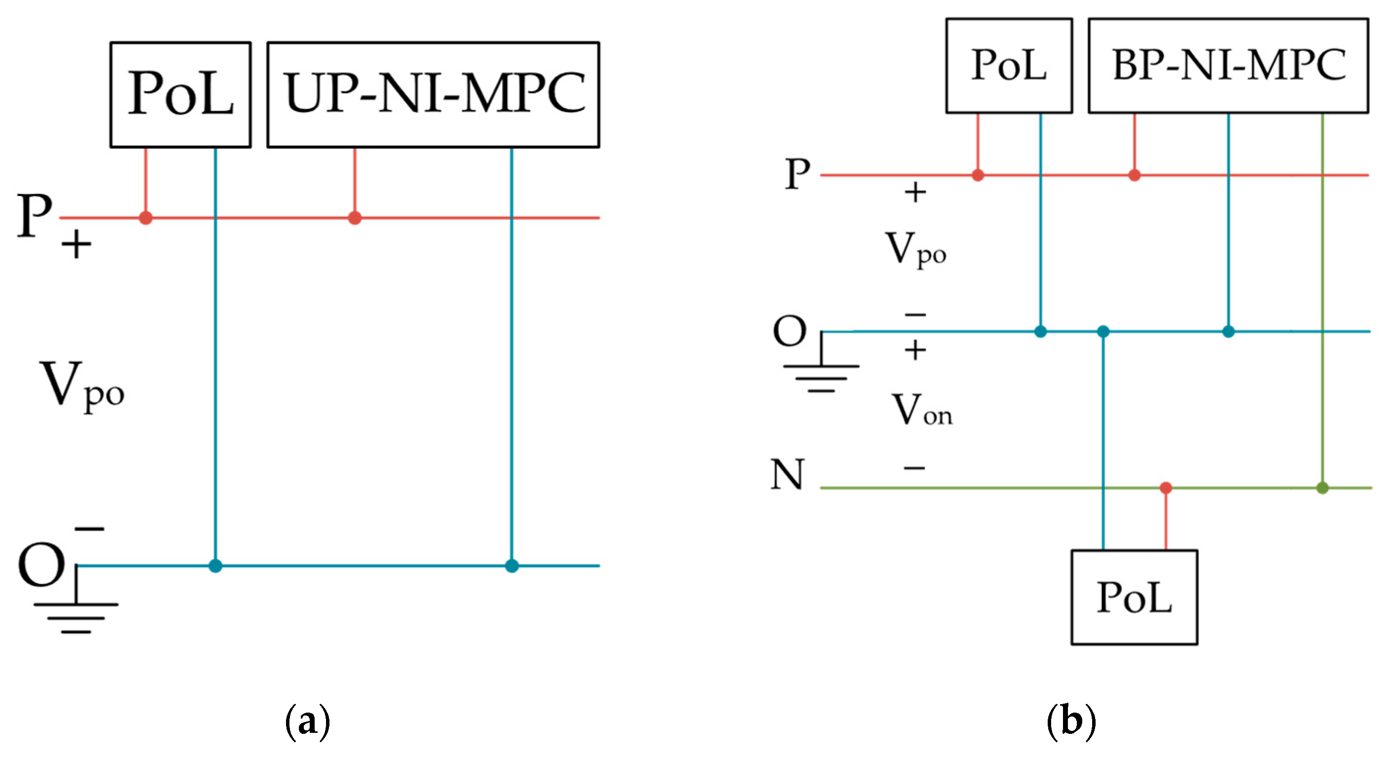
2. General Characteristics of UP and BP-NI-MPCs

Even though MPCs are designed to reduce overall complexity system-wise, it becomes apparent that they are a little more complex compared to a SISO module converter-wise. However, they can still be examined systematically, and they have several common features.
Depending on the system conditions, MPCs may be operating in the subsequent modes [1], which are also represented in Figure 1:
  • SISO I: The RES is supplying power to the load, working at Maximum Power Point (MPP). In this mode the ESS remains idle or is disconnected. In the first case, the power provided by the RES is supplying the load adequately and the energy stored in the ESS is not required. In the second case, operation of the system administrator or a fault caused the ESS to be disconnected or destroyed.
  • Double-Input Single-Output (DISO): The RES cannot serve the load entirely due to reduced sun irradiance, partial shading, or increased load demand. Therefore, the ESS discharges for the converter to meet the load requirements.
  • SISO II: The RES is not producing energy and the load is supplied entirely by the ESS. The RES may be missing, malfunctioning, or operating under extreme shading conditions.
  • Single-Input Double-Output (SIDO): The RES produces a surplus of energy that enables ESS charging besides supporting load demand.
  • SISO III: The excess power from other components of the DC-MG can be used for ESS charging, given that there is a bidirectional power path between ESS and DC-MG ports.
In the context of residential DC-MG applications, MPCs need to exhibit the following characteristics:
  • High voltage gain, adequate for interfacing RES and ESS modules with the DC Bus whose voltage level is currently stabilizing on 380–400 V [14] for unipolar and varies between ±170 V and ±269 V for bipolar buses [15].
  • High component sharing among the different power paths, leading to increased power density.
  • A bidirectional power flow port for the integration of the ESS, allowing its charging and discharging. Ideally, the output port should be bidirectional as well, so that the ESS can be charged from both the RES and the DC-MG bus.
  • Soft switching of as many of their semiconductors as possible, for minimization of switching losses and increased efficiency.
  • Low voltage stress on semiconductors, facilitating the selection of components with lower conduction resistance.
  • Continuous input currents for RES and ESS, reducing required filtering. High current ripple at the RES input current greatly affects MPP tracking and may lead to reduced power generation [16]. Additionally, even though the lifetime of ESSs (usually batteries) are dependent on many parameters, high current ripple may enhance aging [17].
  • Reduced component count and, thus, reduced cost, weight, and volume.
  • Increased port number, if possible, for higher integration and power levels. Additionally, that will increase system reliability by integrating different RES and ESS types.
From a control perspective, the primary objectives are to manage the MPP operation of the RES ports and regulate the output voltage [18]. The MPCs discussed below are designed to operate either in standalone applications, creating a small-scale DC-MG, or in larger scale interconnected DC-MGs. In standalone applications, MPCs must possess the capability to regulate their output voltage. Conversely, in the case of larger interconnected DC-MGs, the necessity for output control hinges on whether the DC-MG operates in an islanded or grid-connected mode, as highlighted by [19]. Notably, in Bipolar DC Microgrids (BP-DC-MGs), where MPCs are likely connected to a bus with a voltage balancer, it becomes possible to omit the MPC’s output voltage regulation. This omission can streamline control requirements, freeing up one control variable, as discussed in [4].
If feasible, the charging process of the ESS should also be controlled with Constant Current-Voltage or more advanced methods [20] and limiting parameters, such as the maximum charging current, must be respected.

3. Voltage Boosting and Switching Losses Reduction of NI-MPCs
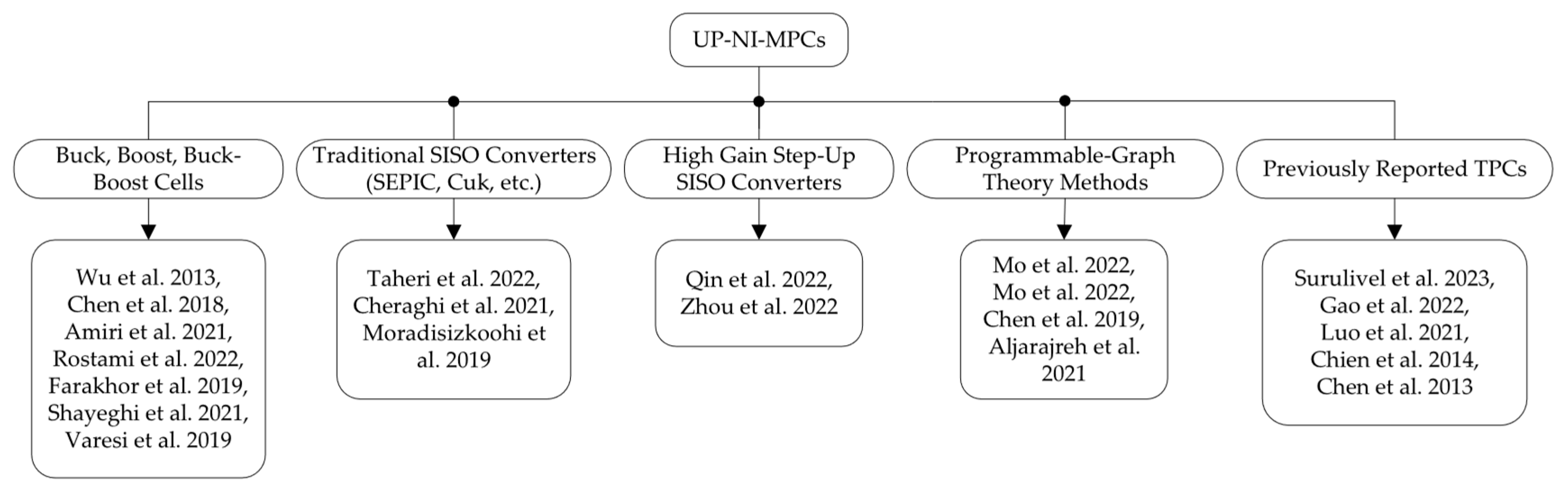
In this section, the two most important parameters in the design of NI-MPCs are studied, based on data extracted from the literature. High voltage conversion capability is a crucial aspect that greatly impacts the design process of ΝΙ DC-DC MPCs. In the literature [21], several voltage-boosting methods (VBMs), including charge pumps based on capacitive energy transfer, voltage multiplier cells (VMCs) relying on diode and L/C components, switched inductors that implement parallel magnetizing and series demagnetizing, and Coupled Inductors (CIs) with turn-ratio-based boosting capability are presented. Focusing on facilitating new designs, the utilization of each method in existing NI-MPCs is recorded and the results are presented in Figure 3. It becomes clear that switched inductors, coupled inductors, and VMCs are the most encountered VBMs in NI-MPCs. Those are frequently combined, with the secondary winding of a coupled inductor forming a VMC by charging a capacitor through a diode.
A higher number of semiconductors, compared to a SISO converter, is usually necessary to maintain the required degrees of freedom as the number of interfaced ports increases. The trend towards reducing the converter volume by minimizing its passive components drives the switching frequency to higher levels as well. Those conditions, along with the integration of VBMs, make it challenging to preserve high efficiency due to the increase of conduction and switching losses. It is well established in the literature that the high voltage-boosting capability of boost-based converters imposes increased voltage stress on the switching devices that leads to more switching losses. Therefore, auxiliary circuits are added to the MPC to achieve zero-voltage switching and zero-current switching for as many semiconductors as possible. As shown in Figure 4, a little over half the UP-NI-MPCs studied utilize soft-switching techniques for increased efficiency. The use of wideband gap (GaN or SiC) devices as a more technical and market-dependent solution would not cure the converter’s drawbacks (e.g., the extreme voltage overshoots on the transistor of a switched inductor) but it would help to overcome the limitations of the switching device (e.g., by reducing the switching interval). Therefore, these devices will also lead to reduced conduction losses. However, conduction losses cannot be easily limited, as the increase of switching frequency and the resulting high voltage levels and overshoots necessitate the selection of devices with a higher voltage rating, and consequently, higher conduction resistance.

4. UP-NI-MPCs

In the ensuing subsections, the investigation zeroes in on UP-NI-MPCs and delves into their topology derivation methods. Within each section, power converters crafted through a uniform procedure are systematically grouped, along with comprehensive commentary and comparisons on their distinct characteristics. In each subsection, one representative topology is presented in the form of a figure so that the derivation process can be easily understood. The culmination of this analytical process is illustrated in Figure 5, presenting the resulting classification. It is worth noting that, while our examination encompasses MPCs in general, there is a prevailing emphasis on the study of their subcategory, TPCs, within the existing literature. Consequently, the majority of the topologies presented below primarily fall under the TPC category. This is attributed to the fact that there are currently fewer proposed MPC topologies (of higher port number) meeting the required characteristics.

4.1. Converters Derived from Basic Cells

The first approach towards designing an MPC is to build it by combining cells of the three fundamental converters (Buck, Boost, and Buck-Boost) so that the desired number of ports is achieved. Due to their low voltage-boosting capabilities, the developed converters are usually enhanced with VBMs to extract more complex topologies suitable for said application and with auxiliary circuits for soft switching.
Prior to examining specialized converters, it is beneficial to survey general approaches that may aid in the design of the former. In [36], a systematic approach is attempted towards directly extracting TPCs from Double-Input or Double-Output Converters consisting of basic cells. One of the derived converters is shown in Figure 6, along with its initial form (i.e., non-simplified, with raw basic cells). The final converter exhibits pulsating input currents for DISO mode, thus increasing the required input capacitance, and it exhibits low voltage gain, as VBMs are not included in the design process. Similar attempts are made in [37].
Offering continuous RES and ESS current and high voltage gain, Amiri et al. [22] propose a modular MPC based on boost basic cells along with an algorithm for the independent control of each port. Nevertheless, no bidirectional port is offered for ESS integration and the component sharing is low, as only the multiplier circuit is common for all ports. In [23], a Four-Port Converter that integrates two different RESs for increased reliability, an ESS and the load is proposed. It is based on an interleaved boost converter, a bidirectional Buck-Boost converter for the ESS port and a Cockcroft-Walton VMC. It achieves a high voltage gain of 20 and continuous input currents but has a high component count and lacks soft switching, leading to reduced efficiency. The researchers in [24] designed a converter with two boost cells where the inductors remain separate while the semiconductor switches are merged. To control the charging and discharging of the ESS, an additional network of two switches and one diode is implemented. It is interesting that, unlike most cases, where MPCs are selected to operate in Continuous Conduction Mode (CCM), here the proposed converter is analyzed for both CCM and Discontinuous Conduction Mode (DCM) operation. The existence of separate inductors for each input port leads to continuous RES/ESS currents but increases the volume of the system. Even though no soft-switching techniques are utilized, the efficiency remains relatively high (92–96%) because only one switch is placed in the main power path. However, the ratings of the switch must be selected with care, as the current that magnetizes both inductors passes through it.
In all approaches above, ESS cannot be charged from the DC Bus, without further modification of the topologies. This is a common problem in topologies extracted from basic cells with 1-quadrant output semiconductors. In some cases, like the topology presented in Figure 6, replacing D 3 with a semiconductor switch (e.g., MOSFET) will permit bidirectional power flow in SISO-III mode. On the contrary, Shayeghi et al. [25] combine two boost cells and switched capacitors to present an UP-NI-MPC with continuous input currents and bidirectional power flow, allowing the converter to operate either in boost or in buck mode. However, due to its simple form, the converter exhibits low voltage gain and no soft-switching behavior, leading to a peak efficiency below 95%. Finally, the MPC in [26] has a bidirectional power flow path between the DC Bus and the ESS as well. The designers have combined boost cells with capacitor-diode VMCs to achieve the required voltage gain without using coupled inductors. The suggested topology has a built-in modularity feature, which is also discussed in detail in the paper. Nevertheless, a large number of switches and inductors is integrated in the converter, increasing the need for driving circuits, the cost, and the volume of the system. The high voltage gain (~20) and the high component count have also affected the efficiency of the MPC, as it reaches 91% at 200 W.

4.2. Converters Derived from Traditional SISO Converters

Instead of combining individual cells, several attempts utilize traditional topologies such as SEPIC, ZETA, or Cuk converters and make arbitrary modifications to obtain the MPC version. In [27], a TPC SEPIC-based converter with CI and voltage lift cell is proposed. Besides high component count, the topology imposes restrictions on the sources that can be interconnected, as the RES port must have lower voltage compared to the ESS port, which is a common problem on converters combining sources via diode parallelization. Furthermore, mechanical switches are used for topology reconfiguration, leading to reduced life expectancy. Likewise, ref. [28] combines a SEPIC converter with a CI and a voltage doubler for increased gain. Moreover, a split DC-link for interfacing the output is incorporated. The topology is shown in Figure 7. Moradisizkoohi et al. [29], based on the asymmetrical bidirectional half-bridge, propose a TPC with high power rating (1 kW) and with a bidirectional power path with the DC-MG. Nevertheless, its high efficiency is achieved by using GaN switches and the voltage gain is only double that of the traditional boost converter.

4.3. Converters Derived from High Gain SISO Converters

The development of SISO high step-up converters is preceding that of MPCs and has reached certain maturity [43]. Therefore, by interfacing another input source, they can be employed to extract novel multiport topologies. The TPC of [30] (Figure 8) utilizes two inductors without a multiplier cell and, therefore, its gain is limited to double the gain of the conventional boost converter. Nevertheless, it shows high efficiency, low component count and continuous battery current. To decouple MPP tracking and output voltage control, Pulse Width Modulation plus Pulse Frequency Modulation is implemented. Zhou et al. [31] propose a solution based on a single magnetic element (CI), which exhibits soft switching and reduced voltage stress for all semiconductors. However, the input current of the ESS port is discontinuous, and the continuity of the RES input current is dependent on the leakage inductance of the CI.

4.4. Converters Derived Using Programmable and Graph Theory Methods

Following the trend of computer-aided design, Mo et al. [38] utilize a basic model of a MIMO converter with a single inductor and several switches to create novel MPCs. Initially, all possible combinations coming from the basic model are found. Afterwards, working criterions are applied to get the effective topologies. Instead of performing the procedure manually, a graph-theory-based approach is proposed, utilizing adjacency matrices (Figure 9). From the same research team, a graph-theory-based method for reducing switches in MPCs is proposed in [39]. While promising, further research is needed before an implementation in real-world applications. The method yields results based on an initial non-optimized solution and is limited to similar form converters. It does not allow for the use of VBM methods or auxiliary circuits as a design prerequisite, because it has a component-based rather than circuit-based scope of search. Furthermore, the manual selection of applicable topologies from a potentially large pool of results is also necessary.
Chen et al. [40] propose a programmable methodology for deriving TPCs that can be extended to N ports. The derivation is based on applying certain rules to extract all the physically feasible converters, coming from connecting the ports to a set of inductor-switch cells. This work opens interesting research paths as several topologies can be developed at once and the application of more rules that are application specific can be applied to get customized results. However, no ESS port is considered and the experimentally tested prototype contains two separate output ports instead. In [41], a systematic topology derivation of TPCs is attempted, based on the power flow graph tool. Specifically, bidirectional power paths are considered for both the ESS and the DC Bus, making the system suitable for DC-MG applications. The derived architectures are reviewed regarding their efficiency and complexity, based on the stages required for power transfer between any two ports, and their reliability. However, this method requires manual effort for the derivation of the complete set of available power configurations and the elimination of the impractical ones. Consequently, it is difficult for it to be generalized for the design of MPCs with more than three ports.

4.5. Converters Derived from Other TPCs

Other researchers, like Surulivel et al. [42], head towards improving the suitability of an existing TPC. They use coupled inductors to enhance the design of a converter proposed in the literature. The current ripple of the RES and ESS ports is examined, taking into consideration the inductance variation due to the bidirectional current of the ESS port. It is proven that inductor coupling may lead to current ripple reduction if certain conditions are met. Based on the existing TPC of [36] that was presented in Figure 6, i.e., a single inductor boost TPC, a high-gain TPC is proposed in [32] by incorporating a boost-flyback converter in the previous design. The converter has a low component count, as only three switches and one magnetic component are used, with the latter also causing the currents of the input ports to be discontinuous. Furthermore, the output of the TPC consists of a split capacitor DC-link, which may be useful in applications where two different outputs are needed. Starting from the same three-port boost converter, coupled inductors were utilized in [33], as shown in Figure 10, to form the common voltage multiplier cell used in other topologies above, but the semiconductors are not soft switched, leading to reduced efficiency. Chien et al. [34] present a converter resembling those in the previous two implementations. Notably, their design diverges by introducing capacitive inverters (CIs) separately, departing from the integration seen in the inductor of the simple boost TPC. Unfortunately, this alteration results in an upswing in the overall component count. Despite this challenge, their approach incorporates capacitive voltage lift and a VMC to attain the necessary gain while ensuring continuous input current for the RES and ESS ports. It is worth noting, however, that this comes at a cost, as three capacitors are placed in series with the power flow path, potentially impacting reliability if electrolytic capacitors are used. Several other topologies, like the one proposed in [35], suffer from high component count accompanied by reduced efficiency.

4.6. Comparative Study and Conclusions on UP-NI-MPCs
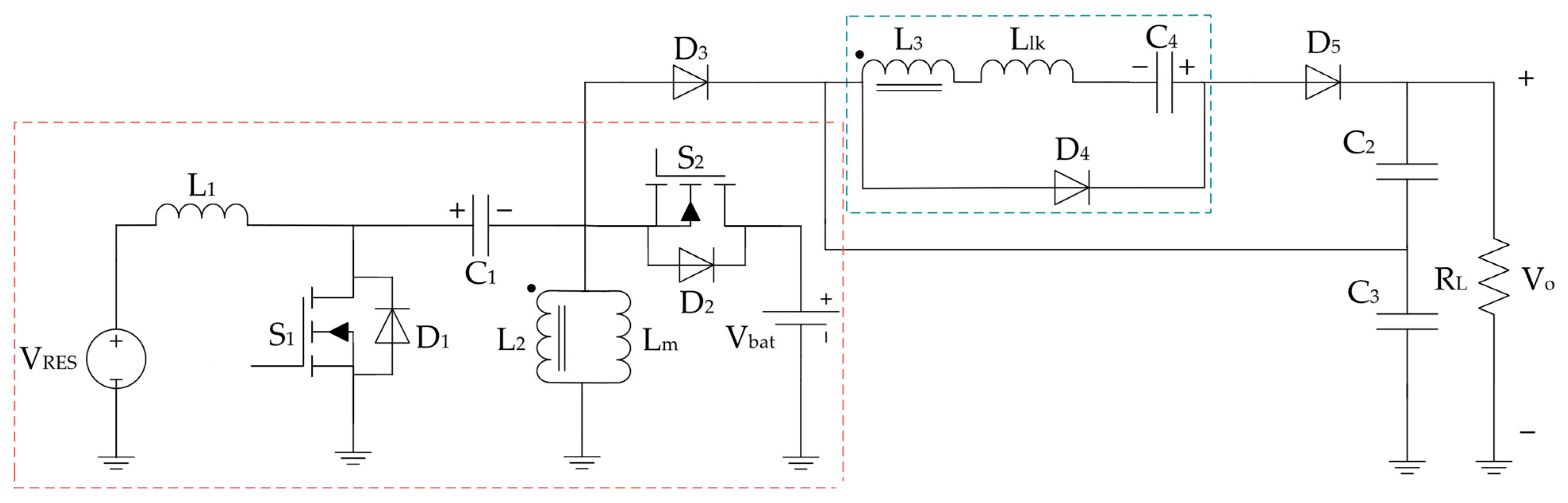
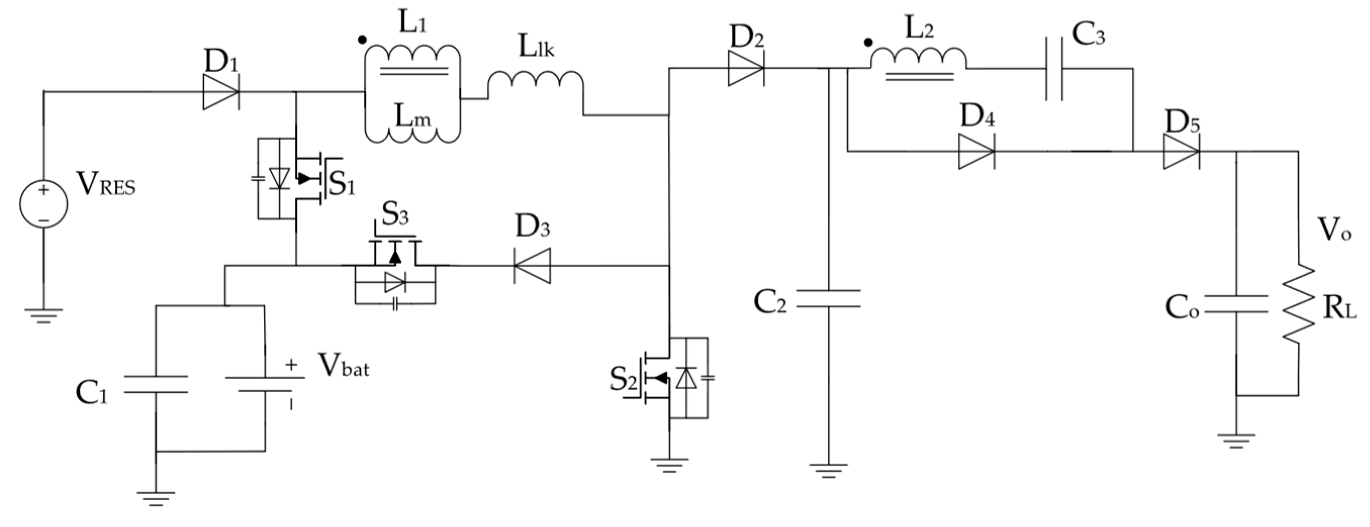
As shown in previous subsections, there are five methods from which a novel MPC topology can be derived. The frequency of their usage based on the proposed topologies indicates that the conception from basic cells is the most popular solution. Unsurprisingly, the boost cell constitutes the fundamental cell, considering the need for high voltage boosting. This straightforward approach leads to a robust solution, leaving the researcher with the freedom to cure the topology’s weaknesses caused by its simplicity. Following that, the modification or optimization of previously reported TPCs seems to gather a lot of interest. Most researchers work on specific TPCs that are well accepted in the literature, as, for instance, the one proposed by Wu et al. [36]. Then, graph-theory-based methods are used more and more in recent years since they allow a more systematic search of MPC topologies. Currently, no solution can serve as a general tool and, therefore, there seems to be plenty of space for research in the field. Finally, techniques as the topology extraction from traditional SISO or high gain SISO converters are reported in the literature, but at a lower rate.
Based on the above, the use of VBMs to increase the boosting capabilities of MPCs is widely reported in the literature. In Figure 11, a comparison of the step-up capabilities of the reviewed UP-NI-MPCs is presented. Some studies compensate for the limited voltage gain by connecting input sources in series. This approach has two aspects to be explored. First, it is possible to connect the RES and ESS ports in series [27], which can result in reduced gain if one source fails. Second, multiple RES may be connected in series [29,30], which requires considering the impact of RES module mismatch, shading, and hotspot bypassing (in the case of PVs) [44], regarding power generation and converter gain.
It is evident that the focus is on designing converters with three ports. However, the low power rating of a TPC unit, which is typically obtained by integrating a single RES module or a small series of them, is inadequate for residential power needs. Thus, a modular architecture must be adopted. This raises concerns regarding the implementation of the ESS. In most cases, it is unpractical to split the ESS into small units as it increases installation and maintenance costs. One exception, though, might be the usage of repurposed (second-life) ESSs of different chemical types, as they cannot be seamlessly combined into a single ESS. Moreover, these systems have most likely undergone distinct aging processes, thereby underscoring the necessity for separate ESS configurations. Regardless of that, a possible solution is to design the MPC so that all ESS ports can be connected in parallel to the central ESS, as depicted in [45].
Regarding the sizing of the MPCs, most works lean towards selecting the ESS voltage level to be similar or higher than that of the RES, due to topology restrictions. The switching frequency is selected between 50–100 kHz and soft switching is applied to selected or the total of semiconductors. One important design trade-off is the selection of magnetic components. The decision to use a shared inductor for all ports reduces the volume and cost of the converter, but it usually leads to discontinuous input currents in DISO mode. So, some researchers are forced to utilize dedicated inductors that solve this problem but reduce power density. The main features of the converters reviewed above are summarized in Table 1. The efficiency of the converters is presented for the SISO I, DISO, and SIDO operating modes in that specific order, while the displayed gain is for SISO I mode. The minus symbol in the soft-switching column indicates that not all switches exhibit soft-switching characteristics.
Utilizing the information contained in Table 1, a figure of merits can be created for the topologies presented in previous subsections (Figure 12). The parameters examined are normalized compared to Table 1. The provided insight on the advantages and weaknesses of current implementations will be useful for the researchers aiming to optimize or increase the suitability of those converters. A general observation is that most researchers focus on the increase of voltage gain capability, rather than that of power level. Examining the topology in [23], the highest gain is achieved, however this level of voltage boosting comes with a cost for efficiency and power level, which are both in the middle of the total ranges. Aiming to optimize different design objectives, the researchers in [29] achieve a high power rating, which is double that of the next topology, while managing to maintain the highest efficiency. It must be remembered, though, that the usage of wide-bandgap devices is catalytic to this achievement. On the other hand, this MPC suffers from one of the lowest voltage gains leading to the need for increased input voltage level. Finally, [22] seems to be the best compromise solution thus far, as it displays the second-best voltage gain capability along with the third-best power level and efficiency. Furthermore, it exhibits continuous current on RES and ESS ports, which none of the previously discussed topologies in this paragraph has.
Concerning the incorporation of the proposed MPCs in the residential DC-MGs, to the best of the authors’ knowledge, no analysis is performed in any study about the effects of the converter operation on the network’s power quality and behavior during transients. Future works in the field need to examine the operation of MPCs under the framework of real-life operation of DC-MGs. This leads to the need to study MPCs as a black box component. To achieve that with reduced computational efforts for both analysis and simulations, mathematical modelling of MPCs must be performed instead of using a switching model. However, the non-linear equations imposed by the algebraic constraints of RESs (e.g., the implicit current-voltage equation in PVs) [46] or the algebraic constraints of design parameters of MPCs (e.g., the voltage level of different ports) [47] increase modelling complexity as the use of differential algebraic equations is required.
As stated in [48], MPCs need to comply with the available standards, so that the lifetime of RES, ESS, and other components of the system is prolonged, and that EMC compliance is achieved. Nevertheless, standardization on residential DC-MGs is not complete and further effort is required in this direction as well.

5. BP-NI-MPCs

5.1. UP-NI-MPCs Used in BP-DC-MGs

Most of the UP-NI-MPCs reviewed above may be used for interfacing RES and ESS with BP-DC-MGs, because BP-MPCs can be viewed as two Multi Input-Single Output converters with the two outputs connected in series. Depending on the voltage levels of the MG and its design strategy, they will either be connected between a pole and the ground or between the two poles. In both cases, the system will be prone to voltage imbalances due to stochastic changes of load. This leads to the inevitable use of central voltage balancers [11]. Finally, the required hardware is doubled to supply both poles.

5.2. ΒP-NI-MPCs Suggested in the Literature

For these reasons, there have been attempts to design MPCs with bipolar output and inherent voltage balancing capability. In [49], a single-input bipolar-output converter is proposed. The converter does not have a port for ESS, but this can be included based on the methods presented in previous paragraphs. The bipolar output of the converter is self-balancing, meaning that any load imbalances do not affect voltage regulation. The converter uses only one active switch, which reduces component count, but requires advanced control techniques for the output voltage regulation and RES MPP tracking to be performed simultaneously. Tanha et al. [50] propose a converter with five ports (Figure 13) that, despite its large number of components, can integrate two RESs and one ESS to either a UP or a BP DC MG. This NI-MPC is based on a quadratic boost converter and therefore it exhibits continuous input currents. However, no soft-switching techniques are used, leading to reduced efficiency for the converter.
Several attempts are focused on Bipolar Buses of lower voltage levels (i.e., ±24). Prajof et al. [51] propose a NI-BP-MPC, with two unidirectional input ports for RES. Again, an ESS port could be implemented by making one of the input ports bidirectional. In [52], a family of BP-NI-MPCs with a relatively high power rating (2 kW) is presented. All inputs are connected to the same inductor or switched inductor cell through switches and the bipolar output is created with a Greinacher voltage doubler or a synchronous buck converter. However, a high number of semiconductors are used. Prabhakaran et al. [53] proposes a single inductor-based topology with two RES ports and reduced component count, but the efficiency was relatively low (86.5%). In [54], a Four-Port converter with a bidirectional port is presented, that is based on the combination of a SEPIC and a Cuk TPC to achieve the bipolar output. However, the two TPCs are not further unified and, therefore, the high component count with three magnetic elements is inevitable.

5.3. Comparative Study of ΒP-NI-MPCs

From the results reported above, it becomes apparent that only the converters presented in [49,50] can be used as is or with minor modifications for residential applications. However, for the rest of the topologies, both the integration of an ESS bidirectional power port and the increase of the output voltage level are crucial for the further development of BP-NI-MPCs. Furthermore, the design and testing power level of the converters is inadequate and must be increased. Finally, the topology derivation through programmable methods based on graph theory is not currently used in bipolar converter design. This path should be explored, based on the already developed work for UP-NI-MPCs, as a unified method (with different rule application) for both types of buses might be created. The summarized features of the BP-NI-MPCs examined are presented in Table 2. Due to the incompleteness of the characteristics of BP-NI_MPCs, a figure of merits was not created for these converters.

6. Conclusions

In this paper, a comprehensive review and classification of the UP and BP NI-MPCs suitable for residential applications is attempted. Initially, the general MPC characteristics that are required for those applications are discussed, focusing on both hardware and control features. The dilemma between the UP and BP Buses is also analyzed. Later, two essential topics of MPC design, those of voltage boosting and efficiency enhancement, are described and a literature survey is performed to discover the most frequently used methods. Switched inductors, coupled inductors, and VMCs are widespread VBMs, while soft switching for increased efficiency is used by nearly half of the topologies discussed. Then, the UP-NI-MPCs are classified, based on their derivation process, and their basic characteristics are compared and commented. Regarding the topology conception, five methods are noticed in the literature with the one based on converter basic cells being the most widely used. Improving existing TPCs is another popular choice. Given the increased complexity of future MPCs designed to achieve higher integration (with more ports), programmable methods using graph theory gain increasing interest. This will allow a more systematic and rapid approach to the power converter design, as the topology search will be performed by a computer. The review indicates that new designs or optimization of current UP-NI-MPCs is required to achieve higher power density and efficiency. To comprehensively gather and display the characteristics of UP-NI-MPCs, a figure of merits is created, so that future researchers can select any existing topology according to the most important aspects of their application. Subsequently, BP-NI-MPCs reported in the literature undergo a similar review. It is found that they need to be further investigated, as there is little effort on the field, despite the increasing interest in BP-DC-MGs. Regardless of the DC-MG configuration, the adoption of a modular architecture appears to be the most practical and reliable implementation for residential applications. In this approach RES modules will be connected in series to form the unit that will be connected in the RES port while the ESS unit of each MPC module will be connected in parallel with the rest. Additionally, the MPCs of both categories need to be modelled and analyzed as a standalone device and as a DC-MG system component as well. Finally, through this paper, the importance of MPCs is highlighted and the grounds for future research are established, by gaining insight on their design and on the methods to improve their characteristics.

Author Contributions

G.S. performed the literature review and wrote the manuscript; E.T. provided guidance and revised the paper. All authors have read and agreed to the published version of the manuscript.

Funding

This research received no external funding.

Data Availability Statement

Not applicable.

Acknowledgments

The present work was financially supported by the «Andreas Mentzelopoulos Foundation» (Corresponding Author: G.S.).

Conflicts of Interest

The authors declare no conflicts of interest.

Abbreviations

The following abbreviations are used in this manuscript:
RESRenewable Energy Source
ESSEnergy Storage System
DC-MGsDC Microgrid
DPGDistributed Power Generation
SISOSingle-Input Single-Output
MIMOMultiple-Input Multiple-Output
MPCsMultiport Converters
NINon-Isolated
PIPartially Isolated
IIsolated
UPUnipolar
BPBipolar
TPCsThree-Port Converters
MPPMaximum Power Point
DISODouble-Input Single-Output
SIDOSingle-Output Double-Output
VBMsVoltage Boosting Methods
VMCs Voltage Multiplier Cells
CCMContinuous Conduction Mode
DCMDiscontinuous Conduction Mode
CIsCoupled Inductors

References

  1. Haque, M.M.; Wolfs, P.J.; Alahakoon, S.; Islam, M.A.; Nadarajah, M.; Zare, F.; Farrok, O. Three-Port Converters for Energy Conversion of PV-BES Integrated Systems—A Review. IEEE Access 2023, 11, 6551–6573. [Google Scholar] [CrossRef]
  2. Bhattacharjee, A.K.; Kutkut, N.; Batarseh, I. Review of Multiport Converters for Solar and Energy Storage Integration. IEEE Trans. Power Electron. 2019, 34, 1431–1445. [Google Scholar] [CrossRef]
  3. Gonzalez-Longatt, F.; Sanchez, F.; Singh, S.N. Chapter 19—On the Topology for a Smart Direct Current Microgrid for a Cluster of Zero-Net Energy Buildings. In Distributed Energy Resources in Microgrids; Chauhan, R.K., Chauhan, K., Eds.; Academic Press: Cambridge, MA, USA, 2019; pp. 455–481. ISBN 978-0-12-817774-7. [Google Scholar]
  4. Dragičević, T.; Lu, X.; Vasquez, J.C.; Guerrero, J.M. DC Microgrids—Part II: A Review of Power Architectures, Applications, and Standardization Issues. IEEE Trans. Power Electron. 2016, 31, 3528–3549. [Google Scholar] [CrossRef]
  5. Wang, Z.; Luo, Q.; Wei, Y.; Mou, D.; Lu, X.; Sun, P. Topology Analysis and Review of Three-Port DC–DC Converters. IEEE Trans. Power Electron. 2020, 35, 11783–11800. [Google Scholar] [CrossRef]
  6. Savrun, M.M.; Atay, A. Multiport Bidirectional DC–DC Converter for PV Powered Electric Vehicle Equipped with Battery and Supercapacitor. IET Power Electron. 2020, 13, 3931–3939. [Google Scholar] [CrossRef]
  7. Tao, H.; Kotsopoulos, A.; Duarte, J.L.; Hendrix, M.A.M. Transformer-Coupled Multiport ZVS Bidirectional DC–DC Converter with Wide Input Range. IEEE Trans. Power Electron. 2008, 23, 771–781. [Google Scholar] [CrossRef]
  8. Vettuparambil, A.; Chatterjee, K.; Fernandes, B.G. A Multiport Converter Interfacing Solar Photovoltaic Modules and Energy Storage with DC Microgrid. IEEE Trans. Ind. Electron. 2021, 68, 3113–3123. [Google Scholar] [CrossRef]
  9. Kakigano, H.; Miura, Y.; Ise, T. Low-Voltage Bipolar-Type DC Microgrid for Super High Quality Distribution. IEEE Trans. Power Electron. 2010, 25, 3066–3075. [Google Scholar] [CrossRef]
  10. Rivera, S.; Lizana, F.R.; Kouro, S.; Dragičević, T.; Wu, B. Bipolar DC Power Conversion: State-of-the-Art and Emerging Technologies. IEEE J. Emerg. Sel. Top. Power Electron. 2021, 9, 1192–1204. [Google Scholar] [CrossRef]
  11. Gevorkov, L.; Domínguez-García, J.L.; Romero, L.T.; Martínez, À.F. Modern MultiPort Converter Technologies: A Systematic Review. Appl. Sci. 2023, 13, 2579. [Google Scholar] [CrossRef]
  12. Narayanaswamy, J.; Mandava, S. Non-Isolated Multiport Converter for Renewable Energy Sources: A Comprehensive Review. Energies 2023, 16, 1834. [Google Scholar] [CrossRef]
  13. Lu, D.; Aljarajreh, H. Non-Isolated Multiport DC/DC Converters: Applications, Challenges, and Solutions. In Proceedings of the 2022 IEEE 9th International Conference on Power Electronics Systems and Applications (PESA), Hong Kong, China, 20–22 September 2022; pp. 1–5. [Google Scholar]
  14. Fotopoulou, M.; Rakopoulos, D.; Trigkas, D.; Stergiopoulos, F.; Blanas, O.; Voutetakis, S. State of the Art of Low and Medium Voltage Direct Current (DC) Microgrids. Energies 2021, 14, 5595. [Google Scholar] [CrossRef]
  15. Pires, V.F.; Cordeiro, A.; Roncero-Clemente, C.; Rivera, S.; Dragičević, T. DC–DC Converters for Bipolar Microgrid Voltage Balancing: A Comprehensive Review of Architectures and Topologies. IEEE J. Emerg. Sel. Top. Power Electron. 2023, 11, 981–998. [Google Scholar] [CrossRef]
  16. Bharadwaj, P.; John, V. Direct Duty Ratio Controlled MPPT Algorithm for Boost Converter in Continuous and Discontinuous Modes of Operation. In Proceedings of the 2014 IEEE 6th India International Conference on Power Electronics (IICPE), Kurukshetra, India, 8–10 December 2014; pp. 1–6. [Google Scholar]
  17. Goldammer, E.; Gentejohann, M.; Schlüter, M.; Weber, D.; Wondrak, W.; Dieckerhoff, S.; Gühmann, C.; Kowal, J. The Impact of an Overlaid Ripple Current on Battery Aging: The Development of the SiCWell Dataset. Batteries 2022, 8, 11. [Google Scholar] [CrossRef]
  18. Qian, Z.; Abdel-Rahman, O.; Al-Atrash, H.; Batarseh, I. Modeling and Control of Three-Port DC/DC Converter Interface for Satellite Applications. IEEE Trans. Power Electron. 2010, 25, 637–649. [Google Scholar] [CrossRef]
  19. Al-Ismail, F.S. DC Microgrid Planning, Operation, and Control: A Comprehensive Review. IEEE Access 2021, 9, 36154–36172. [Google Scholar] [CrossRef]
  20. Amanor-Boadu, J.M.; Guiseppi-Elie, A.; Sánchez-Sinencio, E. The Impact of Pulse Charging Parameters on the Life Cycle of Lithium-Ion Polymer Batteries. Energies 2018, 11, 2162. [Google Scholar] [CrossRef]
  21. Forouzesh, M.; Siwakoti, Y.P.; Gorji, S.A.; Blaabjerg, F.; Lehman, B. Step-Up DC–DC Converters: A Comprehensive Review of Voltage-Boosting Techniques, Topologies, and Applications. IEEE Trans. Power Electron. 2017, 32, 9143–9178. [Google Scholar] [CrossRef]
  22. Amiri, E.; Khorasani, R.R.; Adib, E.; Khoshkbar-Sadigh, A. Multi-Input High Step-Up DC–DC Converter with Independent Control of Voltage and Power for Hybrid Renewable Energy Systems. IEEE Trans. Ind. Electron. 2021, 68, 12079–12087. [Google Scholar] [CrossRef]
  23. Rostami, S.; Abbasi, V.; Talebi, N. Ultrahigh Step-Up Multiport DC–DC Converter with Common Grounded Input Ports and Continuous Input Current. IEEE Trans. Ind. Electron. 2022, 69, 12859–12873. [Google Scholar] [CrossRef]
  24. Farakhor, A.; Abapour, M.; Sabahi, M. Design, Analysis and Implementation of a Multiport DC-DC Converter for Renewable Energy Applications. IET Power Electron. 2019, 12, 465–475. [Google Scholar] [CrossRef]
  25. Shayeghi, H.; Pourjafar, S.; Hashemzadeh, S.M. A Switching Capacitor Based Multi-Port Bidirectional DC–DC Converter. IET Power Electron. 2021, 14, 1622–1636. [Google Scholar] [CrossRef]
  26. Varesi, K.; Hossein Hosseini, S.; Sabahi, M.; Babaei, E.; Saeidabadi, S.; Vosoughi, N. Design and Analysis of a Developed Multiport High Step-Up DC–DC Converter with Reduced Device Count and Normalized Peak Inverse Voltage on the Switches/Diodes. IEEE Trans. Power Electron. 2019, 34, 5464–5475. [Google Scholar] [CrossRef]
  27. Taheri, S.M.; Baghramian, A.; Pourseyedi, S.A. A Novel High Step-Up SEPIC-Based Non-Isolated Three-Port DC-DC Converter Proper for Renewable Energy Applications. IEEE Trans. Ind. Electron. 2022, 70, 10114–10122. [Google Scholar] [CrossRef]
  28. Cheraghi, R.; Adib, E.; Golsorkhi, M.S. A Nonisolated High Step-Up Three-Port Soft-Switched Converter with Minimum Switches. IEEE Trans. Ind. Electron. 2021, 68, 9358–9365. [Google Scholar] [CrossRef]
  29. Moradisizkoohi, H.; Elsayad, N.; Shojaie, M.; Mohammed, O.A. Pwm plus Phase-Shift-Modulated Three-Port Three-Level Soft-Switching Converter Using Gan Switches for Photovoltaic Applications. IEEE J. Emerg. Sel. Top. Power Electron. 2019, 7, 636–652. [Google Scholar] [CrossRef]
  30. Qin, L.; Qian, T.; Soon, J.L.; Hassan, W.; Tian, M.; Zhou, L.; Ren, L. Transformerless High-Gain Three-Port Converter with Low Voltage Stress and Reduced Switches for Standalone PV Systems. IEEE Trans. Power Electron. 2022, 37, 13468–13483. [Google Scholar] [CrossRef]
  31. Zhou, G.; Tian, Q.; Wang, L. Soft-Switching High Gain Three-Port Converter Based on Coupled Inductor for Renewable Energy System Applications. IEEE Trans. Ind. Electron. 2022, 69, 1521–1536. [Google Scholar] [CrossRef]
  32. Gao, M.; Wang, S.; Yu, W.; Liu, T.; Shi, J. Analysis of a Coupled Inductor Boost Three-Port Converter with High Voltage Gain for Renewable Energy Systems. J. Power Electron. 2022, 22, 2100–2121. [Google Scholar] [CrossRef]
  33. Luo, P.; Guo, L.; Xu, J.; Li, X. Analysis and Design of a New Non-Isolated Three-Port Converter with High Voltage Gain for Renewable Energy Applications. IEEE Access 2021, 9, 115909–115921. [Google Scholar] [CrossRef]
  34. Chien, L.-J.; Chen, C.-C.; Chen, J.-F.; Hsieh, Y.-P. Novel Three-Port Converter with High-Voltage Gain. IEEE Trans. Power Electron. 2014, 29, 4693–4703. [Google Scholar] [CrossRef]
  35. Chen, Y.-M.; Huang, A.Q.; Yu, X. A High Step-Up Three-Port DC–DC Converter for Stand-Alone PV/Battery Power Systems. IEEE Trans. Power Electron. 2013, 28, 5049–5062. [Google Scholar] [CrossRef]
  36. Wu, H.; Sun, K.; Ding, S.; Xing, Y. Topology Derivation of Nonisolated Three-Port DC–DC Converters from DIC and DOC. IEEE Trans. Power Electron. 2013, 28, 3297–3307. [Google Scholar] [CrossRef]
  37. Chen, G.; Jin, Z.; Deng, Y.; He, X.; Qing, X. Principle and Topology Synthesis of Integrated Single-Input Dual-Output and Dual-Input Single-Output DC–DC Converters. IEEE Trans. Ind. Electron. 2018, 65, 3815–3825. [Google Scholar] [CrossRef]
  38. Mo, L.; Huang, J.; Chen, G.; Qing, X.; Hu, Y. Computer-Aided Systematic Topology Derivation of Single-Inductor Multi-Input Multi-Output Converters from Working Principle. IEEE Trans. Circuits Syst. I Regul. Pap. 2022, 69, 2637–2649. [Google Scholar] [CrossRef]
  39. Mo, L.; Chen, G.; Huang, J.; Qing, X.; Hu, Y.; He, X. Graph Theory-Based Programmable Topology Derivation of Multiport DC–DC Converters with Reduced Switches. IEEE Trans. Ind. Electron. 2022, 69, 5745–5755. [Google Scholar] [CrossRef]
  40. Chen, G.; Jin, Z.; Liu, Y.; Hu, Y.; Zhang, J.; Qing, X. Programmable Topology Derivation and Analysis of Integrated Three-Port DC–DC Converters with Reduced Switches for Low-Cost Applications. IEEE Trans. Ind. Electron. 2019, 66, 6649–6660. [Google Scholar] [CrossRef]
  41. Aljarajreh, H.; Lu, D.D.-C.; Siwakoti, Y.P.; Tse, C.K.; See, K.W. Synthesis and Analysis of Three-Port DC/DC Converters with Two Bidirectional Ports Based on Power Flow Graph Technique. Energies 2021, 14, 5751. [Google Scholar] [CrossRef]
  42. Surulivel, N.; Debnath, D.; Chakraborty, C. A Novel Single Coupled-Inductor Boost TPC With Two Inductively Interfaced Ports Suitable for Renewable Energy Integration. IEEE Trans. Ind. Electron. 2023, 70, 4705–4715. [Google Scholar] [CrossRef]
  43. Zaoskoufis, K.; Tatakis, E.C. An Improved Boost-Based Dc/Dc Converter with High-Voltage Step-Up Ratio for DC Microgrids. IEEE J. Emerg. Sel. Top. Power Electron. 2021, 9, 1837–1853. [Google Scholar] [CrossRef]
  44. Hong, Y.-Y.; Pula, R.A. Methods of Photovoltaic Fault Detection and Classification: A Review. Energy Rep. 2022, 8, 5898–5929. [Google Scholar] [CrossRef]
  45. Vettuparambil, A.; Chatterjee, K.; Fernandes, B.G. A Modular Multiport Converter to Integrate Multiple Solar Photo-Voltaic (PV) Modules with a Battery Storage System and a DC Microgrid. IEEE Trans. Ind. Electron. 2022, 69, 4869–4878. [Google Scholar] [CrossRef]
  46. Hayes, B.; Condon, M.; Giaouris, D. Application of the Filippov Method to PV-fed DC-DC Converters Modeled as hybrid-DAEs. Eng. Rep. 2020, 2, e12237. [Google Scholar] [CrossRef]
  47. Markkassery, S.; Mahindrakar, A.D.; Lakshminarasamma, N.; Pasumarthy, R. Modelling of Non-Isolated Single-Input-Multi-Output DC-DC Converter. In Proceedings of the 2018 IEEE International Conference on Power Electronics, Drives and Energy Systems (PEDES), Chennai, India, 18–21 December 2018; pp. 1–6. [Google Scholar]
  48. Mariscotti, A. Power Quality Phenomena, Standards, and Proposed Metrics for DC Grids. Energies 2021, 14, 6453. [Google Scholar] [CrossRef]
  49. Pires, V.F.; Cordeiro, A.; Foito, D.; Silva, J.F.A. Dual Output and High Voltage Gain DC-DC Converter for PV and Fuel Cell Generators Connected to DC Bipolar Microgrids. IEEE Access 2021, 9, 157124–157133. [Google Scholar] [CrossRef]
  50. Mohammadi Tanha, K.; Abbasi, V.; Mohammadi, K. Multi-Application Multi-Port DC–DC Converter Consisting Six Ports with Four Main Operation Modes. IET Power Electron. 2022, 15, 1016–1033. [Google Scholar] [CrossRef]
  51. Prajof, P.; Agarwal, V. Novel Solar PV-Fuel Cell Fed Dual-Input-Dual-Output Dc-Dc Converter for Dc Microgrid Applications. In Proceedings of the 2015 IEEE 42nd Photovoltaic Specialist Conference (PVSC), New Orleans, LA, USA, 14–19 June 2015; pp. 1–6. [Google Scholar]
  52. Ninma Jiya, I.; Van Khang, H.; Kishor, N.; Ciric, R.M. Novel Family of High-Gain Nonisolated Multiport Converters with Bipolar Symmetric Outputs for DC Microgrids. IEEE Trans. Power Electron. 2022, 37, 12151–12166. [Google Scholar] [CrossRef]
  53. Prabhakaran, P.; Agarwal, V. Novel Four-Port DC–DC Converter for Interfacing Solar PV–Fuel Cell Hybrid Sources with Low-Voltage Bipolar DC Microgrids. IEEE J. Emerg. Sel. Top. Power Electron. 2020, 8, 1330–1340. [Google Scholar] [CrossRef]
  54. Tian, Q.; Zhou, G.; Leng, M.; Xu, G.; Fan, X. A Nonisolated Symmetric Bipolar Output Four-Port Converter Interfacing PV-Battery System. IEEE Trans. Power Electron. 2020, 35, 11731–11744. [Google Scholar] [CrossRef]
Figure 1. MPC architecture and operating modes.
Energies 17 00222 g001
Figure 2. (a) Unipolar and (b) Bipolar bus configurations.
Energies 17 00222 g002
Figure 3. Voltage boosting methods used in MPCs proposed in the literature [22,23,24,25,26,27,28,29,30,31,32,33,34,35].
Energies 17 00222 g003
Figure 4. Soft switching applied in MPCs (Y: yes in all switches, Y−: yes in some switches, N: no) [22,23,24,25,26,27,28,29,30,31,32,33,34,35,36].
Energies 17 00222 g004
Figure 5. UP-NI-MPCs classification based on topology derivation method [22,23,24,25,26,27,28,29,30,31,32,33,34,35,36,37,38,39,40,41,42].
Energies 17 00222 g005
Figure 6. MPC derivation from basic cells: (a) Initial topology with basic cells; (b) Final topology after power path merging [36].
Energies 17 00222 g006
Figure 7. MPC derivation from SEPIC [28].
Energies 17 00222 g007
Figure 8. MPC derivation from a high gain SISO converter: (a) Initial high gain SISO converter; (b) The final MPC [30].
Energies 17 00222 g008
Figure 9. MPC derived from a computer-aided method: (a) Transformation of working criterion in graph and matrix forms; (b) One converter fulfilling all working criterions [38].
Energies 17 00222 g009
Figure 10. TPC derivation from a simpler TPC [33].
Energies 17 00222 g010
Figure 11. Ideal step-up capability comparison of existing UP-NI-MPCs [22,23,24,25,26,27,28,29,31,32,33,34,36].
Energies 17 00222 g011
Figure 12. Figure of Merits for UP-NI-MPCs [22,23,24,25,26,27,28,29,31,32,33,34,36].
Energies 17 00222 g012
Figure 13. Five-Port converter for BP-DC-MGs [50].
Energies 17 00222 g013
Table 1. Summarized features of UP-NI-MPCs.
ConverterRES (V)ESS (V)BidirectionalP#3 * (V) Bus (V)SwitchesDiodesCapacitorsInductorsCoupled Inductors F s ** (kHz)Driving MethodSoft-SwitchingEfficiency @ max Load (%) *** P o **** (W)Ideal Gain in CCM *****Discontinuous  I R E S / E S S
[36]3570Y-10033111(3)100PWMN96.4, 97.2, 98500 1 1 D Y
[22]35R24N-50023621100PWMY-, 95.9, -300 N + 2 1 D N
[23]2024Y204004574-50PWMN92.1, 93.2. 90.1250 1 1 D 1 2 ·
2 + ( 1 D 1 ) ( 1 D 2 )
Y
[24]45-5524Y-2003442-50PWMN-, 92, -300 1 1 D 1 2 N
[25]2012Y-903-62-50PWMN-, 94.2, -120 2 1 D N
[26]1015Y-2936254-40PWMN-, 86, -350 2 D 1 1 D 1 2 N
[27]2224Y-2503561150PWMN93.3, 91.7, 92.6100 1 + N + D 1 D Y
[28]2436Y-3802361130PWMY-94.1, 95.2, -200 N · ( 1 D ) D + N + 1 R Y
E N
[29]100-20050-100Y-4004152-100PWM+ PSΥ-, 97.3, -1000 2 1 D Y
[30]16048Y-3002242-56-168PWM+ PFMY-96.1, 97.7, 97.6300 < 2 1 D R Y
E N
[31]3048Y-400425-1100PWMY93.4, 93.7, 95.7200 N + 2 1 D Y
[32]1824Y-180344-150PWMY95.2, 95.1, 93.1200 1 + N · D 1 D Y
[33]2448Y-400355-150PWMN93.4, 95.8, 92.4200 1 + N 1 D Y
[34]2445Y-4003561150PWMN95.9, 93.6, 93.9300 1 + N 1 D N
[35]5248Y-3805052250PWMΥ90.1 @ 0.1 W200-Y
* P#3 stands for Port #3 which can be a RES/ESS second unit; ** Switching Frequency; *** SISO I-DISO-SIDO. **** Output Power ***** SISO I.
Table 2. Summarized Features-BP-NI-MPCs.
ConverterP#1 * (V)P#2 * (V)Bidirectional PortBus (V)SwitchesDiodesCapacitorsInductors F s ** (kHz)Efficiency @ max Load (%) P o *** (kW)
[49]60-N±200146220-0.28
[50]3020Y±18046634094.50.12
[51]3070N±24244130-0.5
[52]100100N±100386250952
[53]3060N±2424413086.50.2
[54]3536Y±24336310094.20.1
* P#1 and P#2 stand for Port #1 and Port #2. In each port a RES or ESS unit is integrated. ** Switching Frequency. *** Output Power.
Disclaimer/Publisher’s Note: The statements, opinions and data contained in all publications are solely those of the individual author(s) and contributor(s) and not of MDPI and/or the editor(s). MDPI and/or the editor(s) disclaim responsibility for any injury to people or property resulting from any ideas, methods, instructions or products referred to in the content.

