Current Collapse Phenomena Investigation in Automotive-Grade Power GaN Transistors
Abstract
:1. Introduction
2. Analysis of Sensing–Clamping Networks Used for the Evaluation of the Dynamic Resistance in Power GaN Transistors
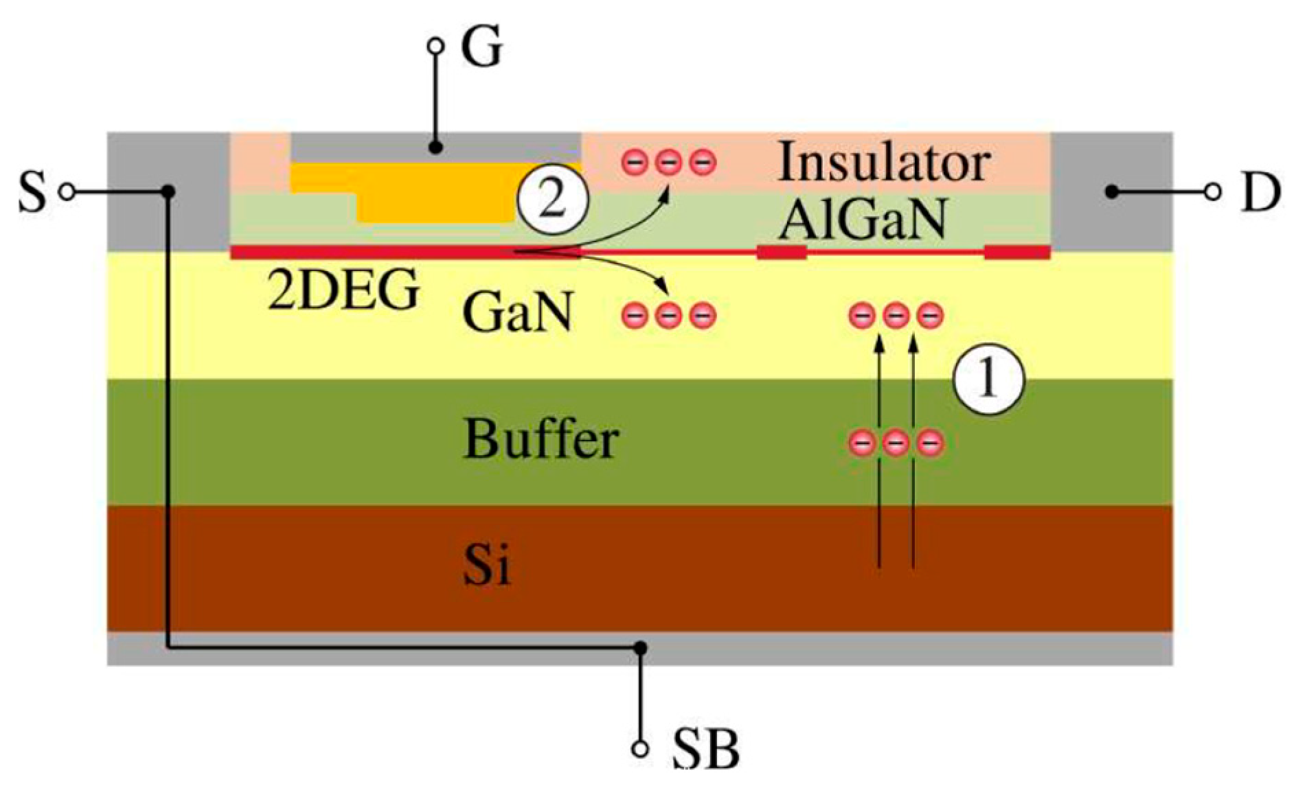
- Off-state trapping.
- 2.
- Hot-electron trapping.
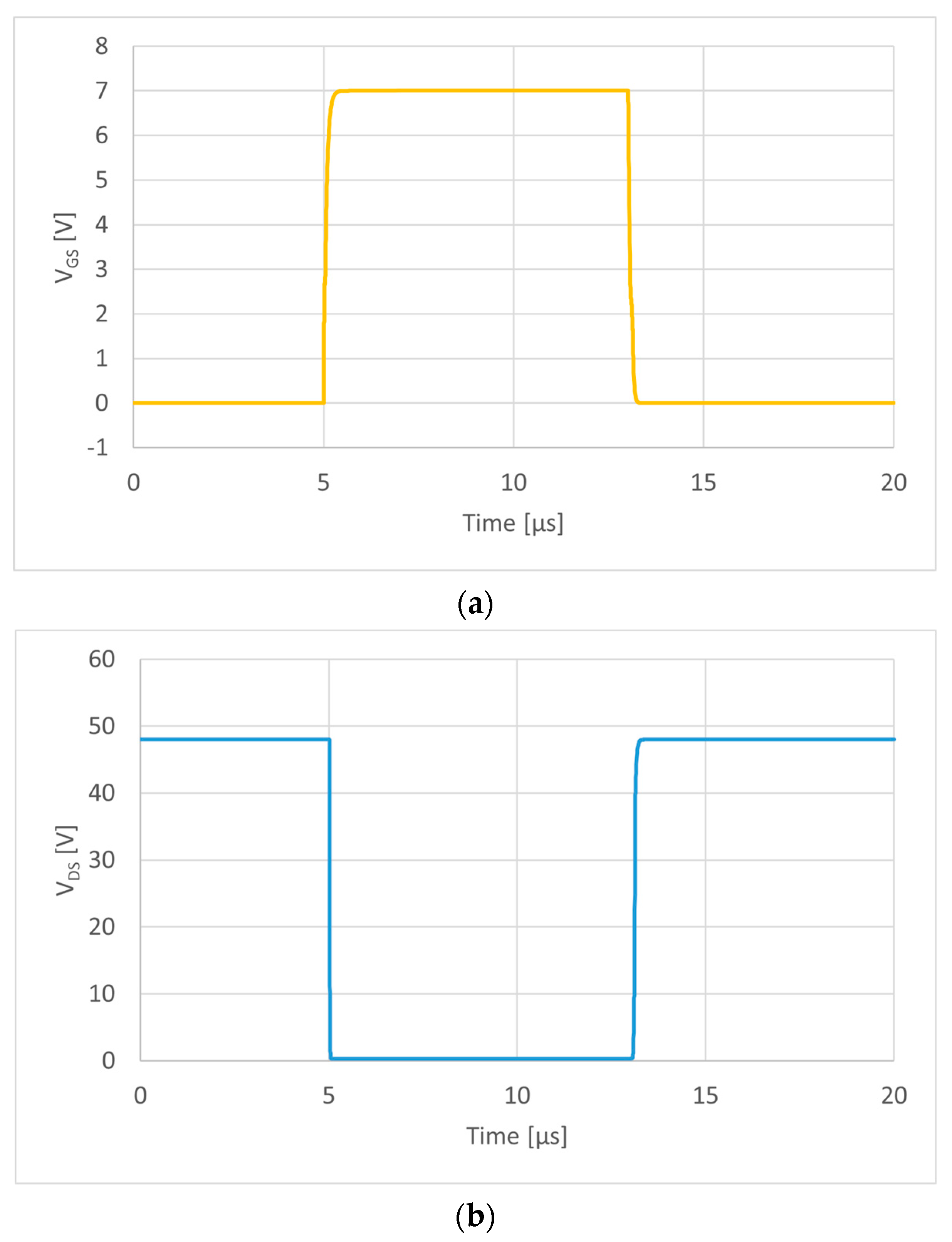
- When the DUT is off, the network works in clamping mode, clamping the to a . Additionally, the clamped voltage must be greater than the to avoid clamping during the on-state. This strategy reduces the amplitude of the voltage swing at the output of the network, avoiding the OOP and increasing the measurement resolution.
- When the DUT is on, the is indirectly measured through the network which is working in sensing mode. During this time interval, the ideal output voltage provided by the network is equal to .
- the clamping mechanism,
- the sensing mechanism.
2.1. Description of Sensing-Clamping Networks
2.1.1. Sensing-Clamping Network N.1
- Clamping mechanism—The resistor R limits the current from the supply so that the clamped voltage is equal to the sum of forward voltage () and the Zener voltage of ():
- Sensing mechanism—When the DUT is on, the output voltage is equal to:where is the offset caused by the leakage current flowing through the resistor. The voltage follows the only after a time interval determined by the RC time constant of the sensing network.
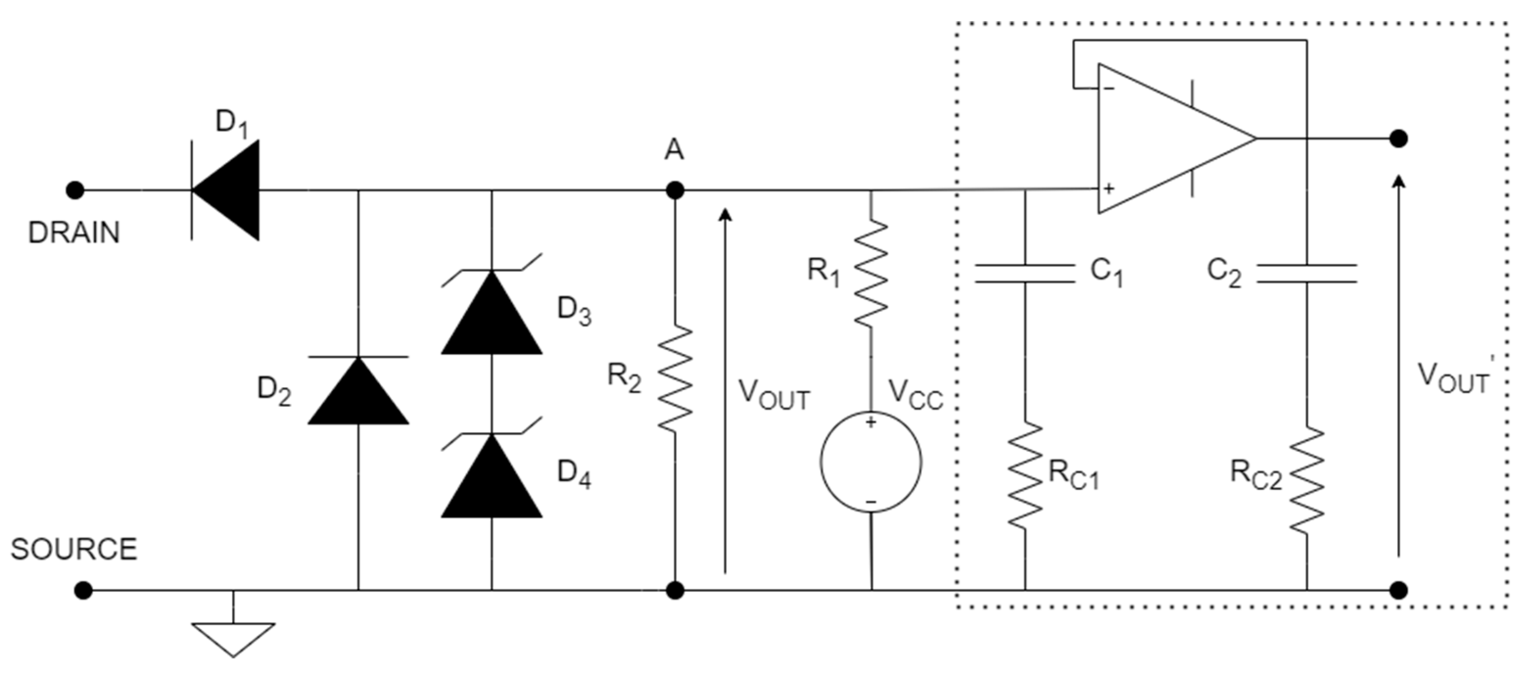
2.1.2. Sensing–Clamping Network N.2
- Clamping mechanism—When the DUT is off, the current flows through M toward the resistor R, thus increasing the potential of node A. The voltage is clamped when the transistor is in the subthreshold region. The clamping voltage is then equal to the gate voltage reduced by the MOSFET threshold one ():
- Sensing mechanism—When the DUT is on, the current flowing through the sensing network decreases, and so does the potential at node A, bringing M to the on-state. The voltage at the output of the network is
2.1.3. Sensing-Clamping Network N.3
- Clamping mechanism—When the DUT is off, the transistor M is in the subthreshold region because the potential at node A increases thanks to the Zener diode . The clamping process is like the previous one since when M enters the subthreshold region, the network clamps the to
- Sensing mechanism—When the DUT is on, the potential at node A decreases and M is also in on-state. The voltage at the output of the network is
2.1.4. Sensing–Clamping Network N.4
- Clamping mechanism—When the DUT is off, the diode is reverse-biased, so the mirrored current flows through the series of diodes toward the ground. The current is set by the resistor R. The diode is always forward-biased. The clamped voltage, acquired between nodes A and B by a differential probe, iswhere N is the number of diodes in the chain and is the forward voltage of one diode.
- Sensing mechanism—When the DUT is on, the two high voltage diodes are forward biased, so the voltage between the network’s output terminals is equal to the DUT on-state one:
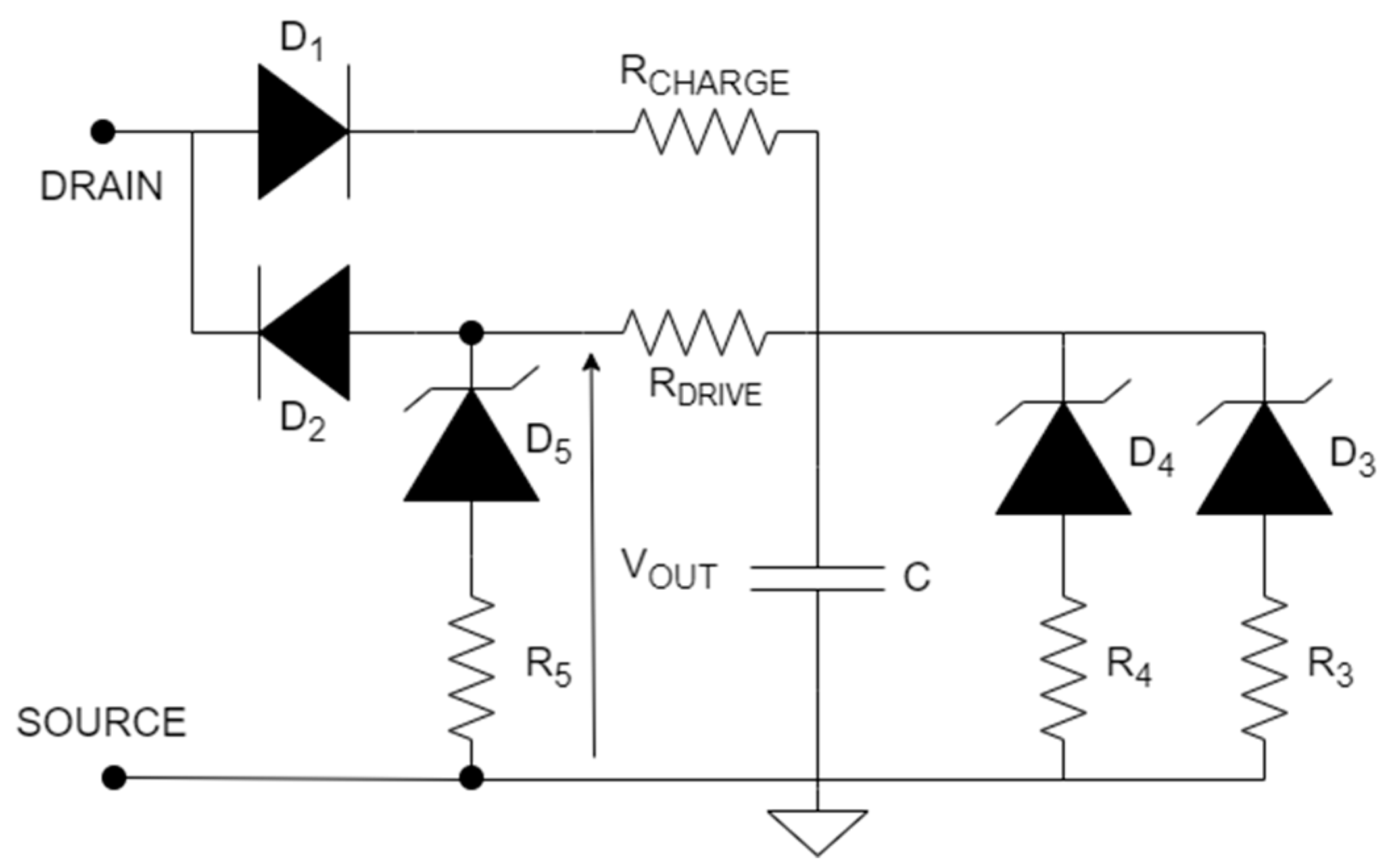
2.1.5. Sensing–Clamping Network N.5
- Clamping mechanism—When the DUT is off, the current flows through , while is reverse biased. The capacitor C is charged during this interval until its voltage is clamped to the Zener voltage of diodes and :
- Sensing mechanism—When the DUT is on, the charges stored in the capacitor flow through toward the DUT, forcing into conduction. The measured voltage at the output is then equal towhere is forward voltage. The resistance is properly chosen to limit the diode’s forward current: a high current may alter its temperature, making temperature dependent on the network’s offset.
2.1.6. Sensing–Clamping Network N.6
- Clamping mechanism—When the DUT is off, the diode is reverse-biased, so the clamped voltage at node A is obtained from the voltage divider:
- Sensing mechanism—When the DUT is on, is forward-biased, so the output voltage is the sum of the diode forward voltage () and the DUT on-state voltage:
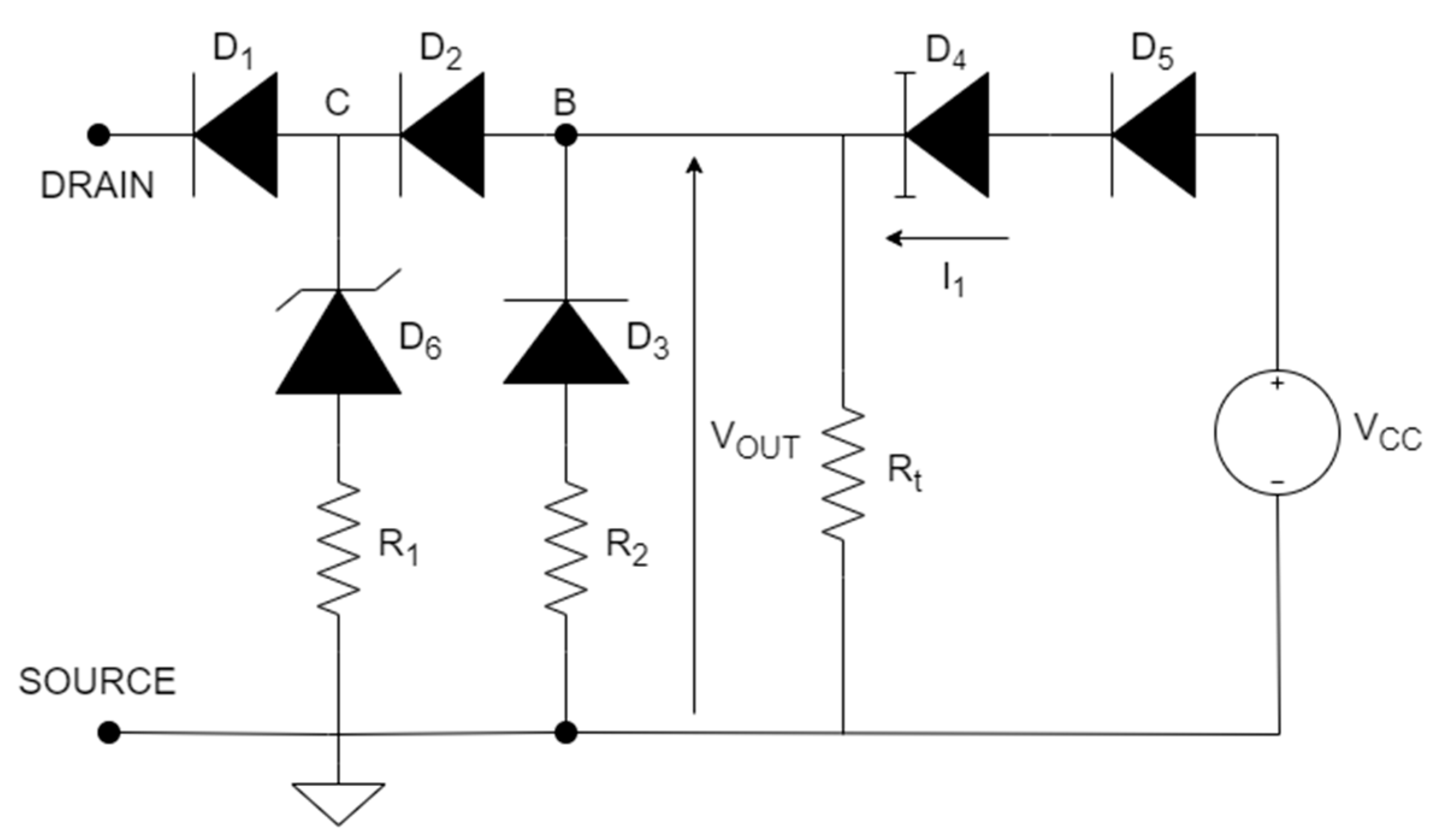
2.1.7. Sensing–Clamping Network N.7
- Clamping mechanism—When the DUT is off, the two isolation diodes are reverse-biased, so the voltage at node C is clamped at the Zener voltage of :
- Sensing mechanism—At the start of the DUT on-state, the potential of B and C become negative because the junction capacitances of and undergo a sudden voltage variation, thus and are clamped by the freewheeling diodes. Without the two freewheeling diodes, the network’s frequency response would be slower, since it depends on the parasitic capacitance of the four main diodes (, , , ). After this initial effect, nodes B and C are charged by the constant current. The can be evaluated when the charging of B and C brings the two diodes and in forward conduction. When the DUT is completely on, the two isolation diodes are both forward conducting ( is their forward voltage), so the voltage at the output of the sensing network is
2.2. Analysis of Characteristics of the Networks
2.3. Test Schematic Simulations
3. Experimental Activity
3.1. Experimental Setup and Test Conditions
- two GPS 3303 Laboratory DC power supply (30 V/3 A)
- one TDK-Lambda GEN 80–65 Programmable DC power supply (80 V/65 A)
- one Keithley 2450 Source Measure Unit (200 V/1 A)
- one Tektronix AFG 3021C Arbitrary function generator
- one Tektronix TDS 5054 Digital phosphor oscilloscope (500 MHz)
- one Tektronix TCP 202 Current probe (30 A)
- one X-Stream 4300 Thermostream (−80 °C to 225 °C)
3.2. Experimental Measurements
4. Conclusions
Author Contributions
Funding
Conflicts of Interest
References
- Matallana, A.; Ibarra, E.; López, I.; Andreu, J.; Garate, J.I.; Jordà, X.; Rebollo, J. Power module electronics in HEV/EV applications: New trends in wide-bandgap semiconductor technologies and design aspects. Renew. Sustain. Energy Rev. 2019, 113, 109264. [Google Scholar] [CrossRef]
- Wen, J.; Zhao, D.; Zhang, C. An overview of electricity powered vehicles: Lithium-ion battery energy storage density and energy conversion efficiency. Renew. Energy 2020, 162, 1629–1648. [Google Scholar] [CrossRef]
- Keshmiri, N.; Wang, D.; Agrawal, B.; Hou, R.; Emadi, A. Current Status and Future Trends of GaN HEMTs in Electrified Transportation. IEEE Access. 2020, 8, 70553–70571. [Google Scholar] [CrossRef]
- Liu, Y.; Yang, S.; Han, S.; Sheng, K. Investigation of Surge Current Capability of GaN E-HEMTs in The Third Quadrant: The Impact of P-GaN Contact. IEEE J. Emerg. Sel. Top. Power Electron. 2019, 7, 1465–1474. [Google Scholar] [CrossRef]
- Scrimizzi, F.; Cammarata, F.; D’Agata, G.; Nicolosi, G.; Musumeci, S.; Rizzo, S.A. The GaN Breakthrough for Sustainable and Cost-Effective Mobility Electrification and Digitalization. Electronics 2023, 12, 1436. [Google Scholar] [CrossRef]
- Zhao, X.; Chen, C.W.; Lai, J.S.; Yu, O. Circuit Design Considerations for Reducing Parasitic Effects on GaN-Based 1-MHz High-Power-Density High-Step-Up/Down Isolated Resonant Converters. IEEE J. Emerg. Sel. Top. Power Electron. 2019, 7, 695–705. [Google Scholar] [CrossRef]
- Pushpakaran, B.N.; Subburaj, A.S.; Bayne, S.; Commercial, B. GaN-Based Power Electronic Systems: A Review. J. Electron. Mater. 2020, 49, 6247–6262. [Google Scholar] [CrossRef]
- Meneghesso, G.; Meneghini, M.; Zanoni, E. Power GaN Devices Materials, Applications and Reliability; Springer: Cham, Switzerland, 2016. [Google Scholar]
- Kozak, J.P.; Zhang, R.; Porter, M.; Song, Q.; Liu, J.; Wang, B.; Wang, R.; Saito, W.; Zhang, Y. Stability, Reliability, and Robustness of GaN Power Devices: A Review. IEEE Trans. Power Electron. 2023, 38, 8442–8471. [Google Scholar] [CrossRef]
- Mauromicale, G.; Rizzo, S.A.; Salerno, N.; Susinni, G.; Raciti, A.; Fusillo, F.; Palermo, A.; Scollo, R. Analysis of the impact of the operating parameters on the variation of the dynamic on-state resistance of GaN power devices. In Proceedings of the 2020 2nd IEEE International Conference on Industrial Electronics for Sustainable Energy Systems (IESES), Cagliari, Italy, 1–3 September 2020; Volumre 1, pp. 101–106. [Google Scholar]
- Vetury, R.; Zhang, N.Q.; Keller, S.; Mishra, U.K. The impact of surface states on the DC and RF characteristics of AlGaN/GaN HFETs. IEEE Trans. Electron Devices 2001, 48, 560–566. [Google Scholar] [CrossRef]
- Gill, L.; DasGupta, S.; Neely, J.C.; Kaplar, J.R.; Michaels, A.J. A Review of GaN HEMT Dynamic ON-Resistance and Dynamic Stress Effects on Field Distribution. IEEE Trans. Power Electron. 2024, 39, 517–537. [Google Scholar] [CrossRef]
- Johwoo, J.; del Alamo, J.A.; Jimenez, J. A simple current collapse measurement technique for GaN high-electron mobility transistors. IEEE Electron Device Lett. 2008, 29, 665–667. [Google Scholar]
- Alemanno, A.; Santarelli, A.; Sangiorgi, E.; Florian, C. Characterization of the Dynamic RON of 600 V GaN Switches under Operating Conditions. Electronics 2023, 12, 943. [Google Scholar] [CrossRef]
- Zhu, H.; Matioli, E. Accurate Measurement of Dynamic ON-Resistance in GaN Transistors at Steady-State. IEEE Trans. Power Electron. 2023, 38, 8045–8050. [Google Scholar] [CrossRef]
- Zulauf, G.; Guacci, M.; Kolar, J.W. Dynamic on-resistance in GaN-on-Si HEMTs: Origins, dependencies, and future characterization frameworks. IEEE Trans. Power Electron. 2019, 35, 5581–5588. [Google Scholar] [CrossRef]
- Badawi, N.; Hilt, O.; Bahat-Treidel, E.; Böcker, J.; Würfl, J.; Dieckerhoff, S. Investigation of the Dynamic On-State Resistance of 600 V Normally-Off and Normally-On GaN HEMTs. IEEE Trans. Ind. Appl. 2016, 52, 4955–4964. [Google Scholar] [CrossRef]
- de Oliveira, E.F.; Noeding, C.; Zacharias, P. Impact of dynamic on-resistance of high voltage GaN switches on the overall conduction losses. In Proceedings of the PCIM Europe 2017; International Exhibition and Conference for Power Electronics, Intelligent Motion, Renewable Energy and Energy Management, VDE, Nuremberg, Germany, 16–18 May May 2017; pp. 1–8. [Google Scholar]
- Cai, Y.; Forsyth, J.A.; Todd, R. Impact of GaN HEMT dynamic on-state resistance on converter performance. In Proceedings of the 2017 IEEE Applied Power Electronics Conference and Exposition (APEC), Tampa, FL, USA, 26–30 March 2017; pp. 1689–1694. [Google Scholar]
- Gelagaev, R.; Jacqmaer, P.; Driesen, J. A fast voltage clamp circuit for the accurate measurement of the dynamic on-resistance of power transistors. IEEE Trans. Ind. Electron. 2014, 62, 1241–1250. [Google Scholar] [CrossRef]
- Badawi, N.; Dieckerhoff, S. A new method for dynamic Ron extraction of GaN power HEMTs. In Proceedings of the PCIM Europe 2015, International Exhibition and Conference for Power Electronics, Intelligent Motion, Renewable Energy and Energy Management, VDE, Nuremberg, Germany, 19–20 May 2015; pp. 1–6. [Google Scholar]
- Yang, F.; Xu, C.; Akin, B. Experimental evaluation and analysis of switching transient’s effect on dynamic on-resistance in GaN HEMTs. IEEE Trans. Power Electron. 2019, 34, 10121–10135. [Google Scholar] [CrossRef]
- Qiuping, Y.; Zhibin, Z.; Peng, S.; Bin, Z.; Yumeng, C. An improved voltage clamp circuit suitable for accurate measurement of the conduction loss of power electronic devices. Sensors 2021, 21, 4285. [Google Scholar]
- Lei, J.; Wang, R.; Yang, G.; Wang, J.; Jiang, F.; Chen, D.; Lu, H.; Zhang, R.; Zheng, Y. Precise Extraction of Dynamic Rdson Under High Frequency and High Voltage by a Double-Diode-Isolation Method. IEEE J. Electron Devices Soc. 2019, 7, 690–695. [Google Scholar] [CrossRef]
- Lu, B.; Palacios, T.; Risbud, D.; Bahl, S.; Anderson, D.I. Extraction of dynamic on-resistance in GaN transistors: Under soft-and hard-switching conditions. In Proceedings of the 2011 IEEE Compound Semiconductor Integrated Circuit Symposium (CSICS), Waikoloa, HI, USA, 16–19 October 2011; pp. 1–4. [Google Scholar]









| Network | Based on | Max Voltage | External Source | Probe Type | Advantages | Weakness |
|---|---|---|---|---|---|---|
| Figure 3 | Zener diode | No | No | passive |
|
|
| Figure 4 | transistor | 600 V | 8 V | passive |
|
|
| Figure 5 | transistor | 600 V | 8 V | passive |
|
|
| Figure 6 | diode | 300 V | 5 V | differential |
|
|
| Figure 7 | SiC diode | 600 V | No | passive |
|
|
| Figure 8 | resistor | 15 V | passive |
|
| |
| Figure 9 | diode | 650 V | 5 V | differential |
|
|
| Test Condition | Temperature | Frequency | Duty Cycle | |||
|---|---|---|---|---|---|---|
| Tested Quantity | ||||||
| 32 V | 48 A | 25 °C | 50 kHz | 40% | ||
| 48 V | ||||||
| 56 V | ||||||
| 48 V | 32 A | 25 °C | 50 kHz | 40% | ||
| 48 A | ||||||
| 56 A | ||||||
| 70 A | ||||||
| Temperature | 48 V | 48 A | −40 °C | 50 kHz | 40% | |
| 25 °C | ||||||
| 125 °C | ||||||
| Frequency | 48 V | 48 A | 25 °C | 30 kHz | 40% | |
| 40 kHz | ||||||
| 50 kHz | ||||||
| 70 kHz | ||||||
| 80 kHz | ||||||
| Duty cycle | 48 V | 48 A | 25 °C | 50 kHz | 15% | |
| 20% | ||||||
| 30% | ||||||
| 40% | ||||||
| 50% | ||||||
| Dev 1 | Dev 2 | Dev 1 | Dev 1 | Dev 1 | |
|---|---|---|---|---|---|
| −40 °C | 1.025 | 1.013 | 0.995 | 1.019 | 0.995 |
| 25 °C | 1.53 | 1.512 | 1.485 | 1.521 | 1.485 |
| 125 °C | 3.075 | 3.039 | 2.985 | 3.057 | 2.985 |
Disclaimer/Publisher’s Note: The statements, opinions and data contained in all publications are solely those of the individual author(s) and contributor(s) and not of MDPI and/or the editor(s). MDPI and/or the editor(s) disclaim responsibility for any injury to people or property resulting from any ideas, methods, instructions or products referred to in the content. |
© 2023 by the authors. Licensee MDPI, Basel, Switzerland. This article is an open access article distributed under the terms and conditions of the Creative Commons Attribution (CC BY) license (https://creativecommons.org/licenses/by/4.0/).
Share and Cite
Basile, A.; Scrimizzi, F.; Rizzo, S.A. Current Collapse Phenomena Investigation in Automotive-Grade Power GaN Transistors. Energies 2024, 17, 230. https://doi.org/10.3390/en17010230
Basile A, Scrimizzi F, Rizzo SA. Current Collapse Phenomena Investigation in Automotive-Grade Power GaN Transistors. Energies. 2024; 17(1):230. https://doi.org/10.3390/en17010230
Chicago/Turabian StyleBasile, Alfio, Filippo Scrimizzi, and Santi Agatino Rizzo. 2024. "Current Collapse Phenomena Investigation in Automotive-Grade Power GaN Transistors" Energies 17, no. 1: 230. https://doi.org/10.3390/en17010230
APA StyleBasile, A., Scrimizzi, F., & Rizzo, S. A. (2024). Current Collapse Phenomena Investigation in Automotive-Grade Power GaN Transistors. Energies, 17(1), 230. https://doi.org/10.3390/en17010230


