
Comprehensive Analysis of Dual-Rotor Yokeless Axial-Flux Motor with Surface-Mounted and Halbach Permanent Magnet Array for Urban Air Mobility

Abstract
:1. Introduction
- (1)
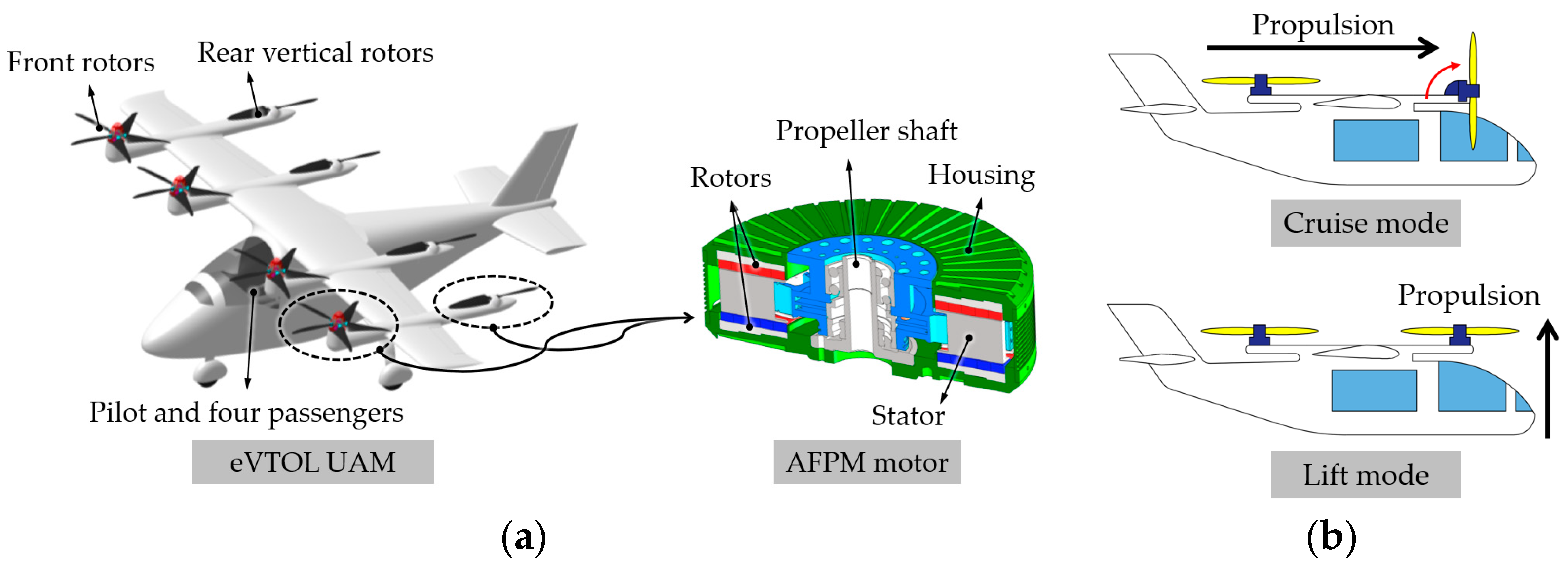
- The development of an AFPM motor faces challenges such as its manufacturability, thermal stability, structural deformation, noise, and vibration. In this paper, the designed dual-rotor YASA-type AFPM motor with a cobalt–iron alloy core was manufactured. The prototype AFPM motor was successfully validated for its rated and maximum output power. Furthermore, its thermal stability was verified through experiments under cooling conditions with a water jacket system. Therefore, the design specifications presented in this work can serve as a reference for AFPM motor design.
- (2)
- It is noteworthy that the comparison results, according to the core materials for the stator and rotor, showed that grain-oriented electrical steel with a silicon–iron alloy core can be an alternative to a cobalt–iron alloy core material, as the output torque decreases slightly.
2. Sizing Equation for AFPM Motor Design
3. Analysis and Experimental Validation of the Proposed AFPM Motor with SPM Array
3.1. Required Design Specifications

3.2. Experimental Validation
3.2.1. Experimental Setups
3.2.2. Measured Results Analysis
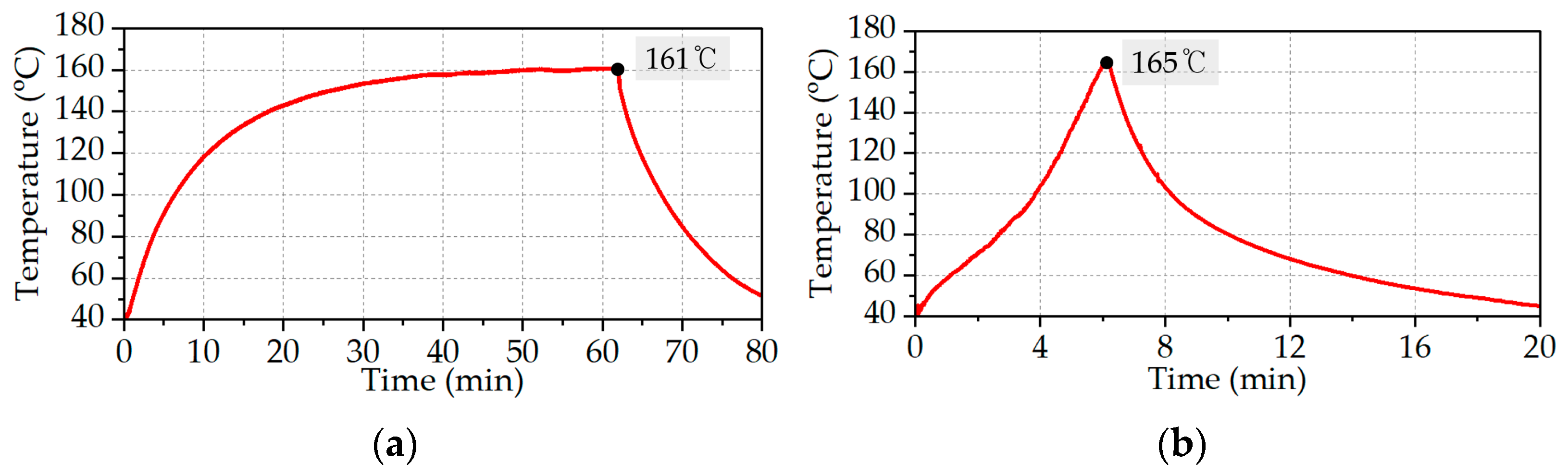
3.2.3. Measurement of Temperature Rises of PM and Windings
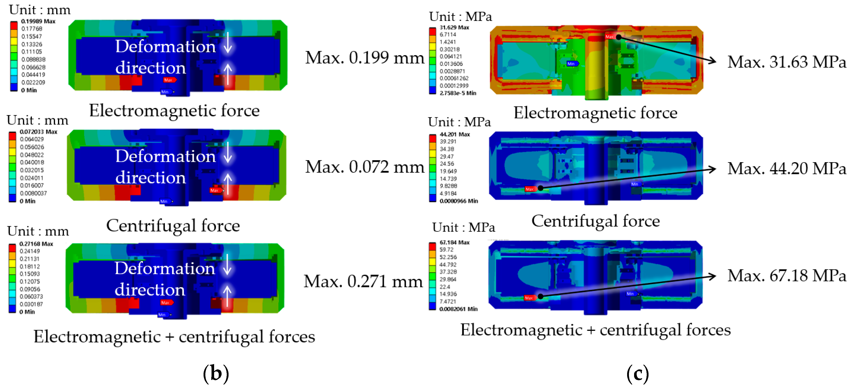
3.3. Air-Gap Length Deformation Analysis (Structure Analysis)
4. Electromagnetic Performance Analysis of Proposed AFPM Motor with SPM Array According to Stator Core Materials to Reduce Cost
4.1. Performance Comparison According to Core Materials for Stator
5. Performance Improvement Design of the Proposed AFPM Motor with HPM Array
6. Conclusions
Author Contributions
Funding
Data Availability Statement
Acknowledgments
Conflicts of Interest
Abbreviations
| AFPM | Axial-flux permanent magnet |
| CFD | Computation fluid dynamics |
| EMF | Electromagnetic force |
| FSCW | Factional slot concentrated winding |
| GHG | Greenhouse gas |
| HPM | Halbach permanent magnet |
| IHPM | Improved HPM |
| ISDW | Integral slot distributed winding |
| LPM | Liters per minute |
| PF | Power factor |
| PM | Permanent magnet |
| RD | Rolling direction |
| RFPM | Radial-flux permanent magnet |
| SMC | Soft magnetic composite |
| SPM | Surface-mounted permanent magnet |
| TD | Transverse direction |
| UAM | Urban air mobility |
| VTOL | Vertical landing and take-off |
| YASA | Yokeless and segmented armature |
References
- Rendón, M.A.; Sánchez, R.; Carlos, D.; Gallo, M.J.; Anzai, A.H. Aircraft Hybrid-Electric Propulsion: Development Trends, Challenges and Opportunities. J. Control Autom. Electr. Syst. 2021, 32, 1244–1268. [Google Scholar] [CrossRef]
- Straubinger, A.; Rothfeld, R.; Shamiyeh, M.; Büchter, K.-D.; Kaiser, J.; Plötner, K. An Overview of Current Research and Developments in Urban Air Mobility—Setting the Scene for UAM Introduction. J. Air Transp. Manag. 2020, 87, 101852. [Google Scholar] [CrossRef]
- Cavagnino, A.; Lazzari, M.; Profumo, F.; Tenconi, A. A comparison between the axial flux and the radial flux structures for PM synchronous motors. IEEE Trans. Ind. Appl. 2002, 38, 1517–1524. [Google Scholar] [CrossRef]
- Rallabandi, V.; Badewa, O.A.; Ozpineci, B.; Ionel, D.M. A Comparison of Outer Rotor Radial and Axial Flux Machines for Application in Electric Vehicles. In Proceedings of the 2023 IEEE International Electric Machines & Drives Conference (IEMDC), San Francisco, CA, USA, 15–18 May 2023; pp. 1–5. [Google Scholar] [CrossRef]
- Zhang, B.; Epskamp, T.; Doppelbauer, M.; Gregor, M. A Comparison of the Transverse, Axial and Radial Flux PM Synchronous Motors for Electric Vehicle. In Proceedings of the 2014 IEEE International Electric Machines & Drives Conference (IEMDC), Florence, Italy, 16–19 December 2014; pp. 1–6. [Google Scholar] [CrossRef]
- Huang, R.; Liu, C.; Song, Z.; Zhao, H. Design and Analysis of a Novel Axial-Radial Flux Permanent Magnet Machine with Halbach-Array Permanent Magnets. Energies 2021, 14, 3639. [Google Scholar] [CrossRef]
- Shao, L.; Navaratne, R.; Popescu, M.; Liu, G. Design and construction of axial-flux permanent magnet motors for electric propulsion applications—A review. IEEE Access Pract. Innov. Open Solut. 2021, 9, 158998–159017. [Google Scholar] [CrossRef]
- Talebi, D.; Gardner, M.C.; Sankarraman, S.V.; Daniar, A.; Toliyat, H.A. Electromagnetic Design Characterization of a Dual Rotor Axial Flux Motor for Electric Aircraft. In Proceedings of the 14th IEEE International Electric Machines and Drives Conference (IEMDC), San Francisco, CA, USA, 15–18 May 2023; pp. 1–8. [Google Scholar] [CrossRef]
- Al-Qarni, A.; Kumar, P.; Koushan, S.; El-Refaie, A. Comparative Analysis Between Various High Specific Power Permanent Magnet Motor Topologies for Aerospace Applications. In Proceedings of the 2022 IEEE Energy Conversion Congress and Exposition (ECCE), Detroit, MI, USA, 9–13 October 2022; pp. 1–8. [Google Scholar] [CrossRef]
- Nishanth, F.; Van Verdeghem, J.; Severson, E.L. A Review of Axial Flux Permanent Magnet Machine Technology. IEEE Trans. Ind. Appl. 2023, 59, 3920–3933. [Google Scholar] [CrossRef]
- Habib, A.; Che, H.S.; Abd Rahim, N.; Tousizadeh, M.; Sulaiman, E. A Fully Coreless Multi-Stator Multi-Rotor (MSMR) AFPM Generator with Combination of Conventional and Halbach Magnet Arrays. Alex. Eng. J. 2020, 59, 589–600. [Google Scholar] [CrossRef]
- Di Gerlando, A.; Foglia, G.; Iacchetti, M.F.; Perini, R. Axial Flux PM Machines with Concentrated Armature Windings: Design Analysis and Test Validation of Wind Energy Generators. IEEE Trans. Ind. Electron. 2011, 58, 3795–3805. [Google Scholar] [CrossRef]
- Mahmoudi, A.; Ping, H.W.; Rahim, N.A. A Comparison between the TORUS and AFIR Axial-Flux Permanent-Magnet Machine Using Finite Element Analysis. In Proceedings of the 2011 IEEE International Electric Machines & Drives Conference (IEMDC), San Francisco, CA, USA, 15–18 May 2011; pp. 242–247. [Google Scholar] [CrossRef]
- Woolmer, T.J.; McCulloch, M.D. Analysis of the Yokeless and Segmented Armature Machine. In Proceedings of the 2007 IEEE International Electric Machines & Drives Conference, Antalya, Turkey, 3–5 May 2007; Volume 1, pp. 704–708. [Google Scholar] [CrossRef]
- Taran, N.; Klink, D.; Heins, G.; Rallabandi, V.; Patterson, D.; Ionel, D.M. A Comparative Study of Yokeless and Segmented Armature Versus Single Side Axial Flux PM Machine Topologies for Electric Traction. IEEE Trans. Ind. Appl. 2022, 58, 325–335. [Google Scholar] [CrossRef]
- Taran, N.; Heins, G.; Rallabandi, V.; Patterson, D.; Ionel, D.M. Evaluating the Effects of Electric and Magnetic Loading on the Performance of Single- and Double-Rotor Axial-Flux PM Machines. IEEE Trans. Ind. Appl. 2020, 56, 3488–3497. [Google Scholar] [CrossRef]
- Geng, W.; Wang, Y.; Wan’g, J.; Hou, J.; Guo, J.; Zhang, Z. Comparative Study of Yokeless Stator Axial-Flux PM Machines Having Fractional Slot Concentrated and Integral Slot Distributed Windings for Electric Vehicle Traction Applications. IEEE Trans. Ind. Electron. 2023, 70, 155–166. [Google Scholar] [CrossRef]
- Yang, J.; Gao, Y.; Chen, J.; Zhang, C.; Lin, J.; Sun, X. Design of Axial Flux Coreless PM Motors with the New Stator Configuration. In Proceedings of the 2023 IEEE 18th Conference on Industrial Electronics and Applications (ICIEA), Ningbo, China, 18–22 August 2023; pp. 574–578. [Google Scholar] [CrossRef]
- Chulaee, Y.; Lewis, D.; Vatani, M.; Eastham, D.M.; Ionel, D.M. Torque and Power Capabilities of Coreless Axial Flux Machines with Surface PMs and Halbach Array Rotors. In Proceedings of the 2023 IEEE International Electric Machines & Drives Conference (IEMDC), San Francisco, CA, USA, 15–18 May 2023; pp. 1–6. [Google Scholar] [CrossRef]
- Wang, C.; Han, J.; Zhang, Z.; Hua, Y.; Gao, H. Design and Optimization Analysis of Coreless Stator Axial-Flux Permanent Magnet In-Wheel Motor for Unmanned Ground Vehicle. IEEE Trans. Transp. Electrif. 2022, 8, 1053–1062. [Google Scholar] [CrossRef]
- Wang, X.; Zhang, G.; Gao, P. Analysis and Optimization of Cogging Torque for Axial Flux Machine with Halbach Permanent Magnet Array. In Proceedings of the 25th International Conference on Electrical Machines and Systems (ICEMS), Chiang Mai, Thailand, 29 November–2 December 2022; pp. 1–6. [Google Scholar] [CrossRef]
- Wang, X.; Zhang, Y.; Li, N. Analysis and Reduction of Electromagnetic Noise of Yokeless and Segmented Armature Axial Flux Motor. In Proceedings of the 25th International Conference on Electrical Machines and Systems (ICEMS), Chiang Mai, Thailand, 29 November–2 December 2022; pp. 1–6. [Google Scholar] [CrossRef]
- Bhagubai, P.P.C.; Bucho, L.F.D.; Fernandes, J.F.P.; Costa Branco, P.J. Optimal Design of an Interior Permanent Magnet Synchronous Motor with Cobalt Iron Core. Energies 2022, 15, 2882. [Google Scholar] [CrossRef]
- Huang, S.; Luo, J.; Leonardi, F.; Lipo, T.A. A Comparison of Power Density for Axial Flux Machines Based on General Purpose Sizing Equations. IEEE Trans. Energy Convers. 1999, 14, 185–192. [Google Scholar] [CrossRef]
- KSEP. Available online: https://www.ksep.co.kr/en/index.html (accessed on 17 December 2023).
- Shin, Y.; Yang, S.; Seo, J. Numerical Analysis of Permanent Magnet Saturation Temperature According to the Change in the Operating Point of 150 kW motor. In Proceedings of the 2021 Korean Soc. Mech. Eng. (KMSE) CAE and Applied Mechanics Division Spring Conference, Online Conference, 25–26 August 2021; pp. 7–8. Available online: https://www.dbpia.co.kr/journal/articleDetail?nodeId=NODE10602607 (accessed on 17 December 2023).
- Yang, S.; Shin, Y.; Cho, Y.; Choi, J.; Seo, J. Analysis of the Cooling Performance Map of the Motor according to the Cooling Path Size and Flow Rate for the UAM. In Proceedings of the 2022 Korean Soc. Aeronaut. Space Sci. (KSAS) Fall Conference, Jeju, Republic of Korea, 16–18 November 2022; pp. 491–492. Available online: https://www.dbpia.co.kr/journal/articleDetail?nodeId=NODE11180683 (accessed on 17 December 2023).
- Kim, H.J.; Choi, J.; Seo, J.-M.; Yang, S. A Numerical Study for Thermal Performance Estimation by the Various Inclined Rotating Fin Array in a Personal Air Vehicle Motor. In Proceedings of the 2022 Korean Soc. Mech. Eng. (KMSE) Conference, Jeju, Republic of Korea, 9–12 November 2022; pp. 1877–1880. Available online: https://www.dbpia.co.kr/journal/articleDetail?nodeId=NODE11182554 (accessed on 17 December 2023).
- Taran, N.; Rallabandi, V.; Ionel, D.M.; Heins, G.; Patterson, D. A Comparative Study of Methods for Calculating AC Winding Losses in Permanent Magnet Machines. In Proceedings of the 2019 IEEE International Electric Machines & Drives Conference (IEMDC), San Diego, CA, USA, 12–15 May 2019; pp. 2265–2271. [Google Scholar] [CrossRef]
- Hebala, A.; Nuzzo, S.; Connor, P.H.; Volpe, G.; Gerada, C.; Galea, M. Analysis and Mitigation of AC Losses in High Performance Propulsion Motors. Machines 2022, 10, 780. [Google Scholar] [CrossRef]
- Winterborne, D.; Jordan, S.; Sjöberg, L.; Atkinson, G. Estimation of AC Copper Loss in Electrical Machine Windings with Consideration of End Effects. In Proceedings of the 2020 International Conference on Electrical Machines (ICEM), Gothenburg, Sweden, 23–26 August 2020; Volume 1, pp. 847–853. [Google Scholar] [CrossRef]


| Specification | Value | ||
|---|---|---|---|
| Rated | Peak | ||
| Output power (kW) | 75.5 | 104 | |
| Rotational speed (rpm) | 1800 | 1800 | |
| Output torque (Nm) | 400 | 550 | |
| Current (Arms) | 172 | 236 | |
| Current density (Arms/mm2) | 17.5 | 24.4 | |
| Specific power (kW/kg) | 2.23 | 3.01 | |
| Specific torque (kNm/m3) | 59.84 | 80.5 | |
| Efficiency range (%) | 93~97 | ||
| Supply voltage (Vdc) | 650 | ||
| Pole/slot configuration | 20/18 | ||
| Outer diameter of stator (mm) | 310 | ||
| Height (mm) | 93 | ||
| Air-gap length (mm) | 1.5 | ||
| Number of turns | 27 | ||
| Winding layers | 2 | ||
| Total weight (kg) | 35.6 | ||
| Total volume (m3) | 0.007019 | ||
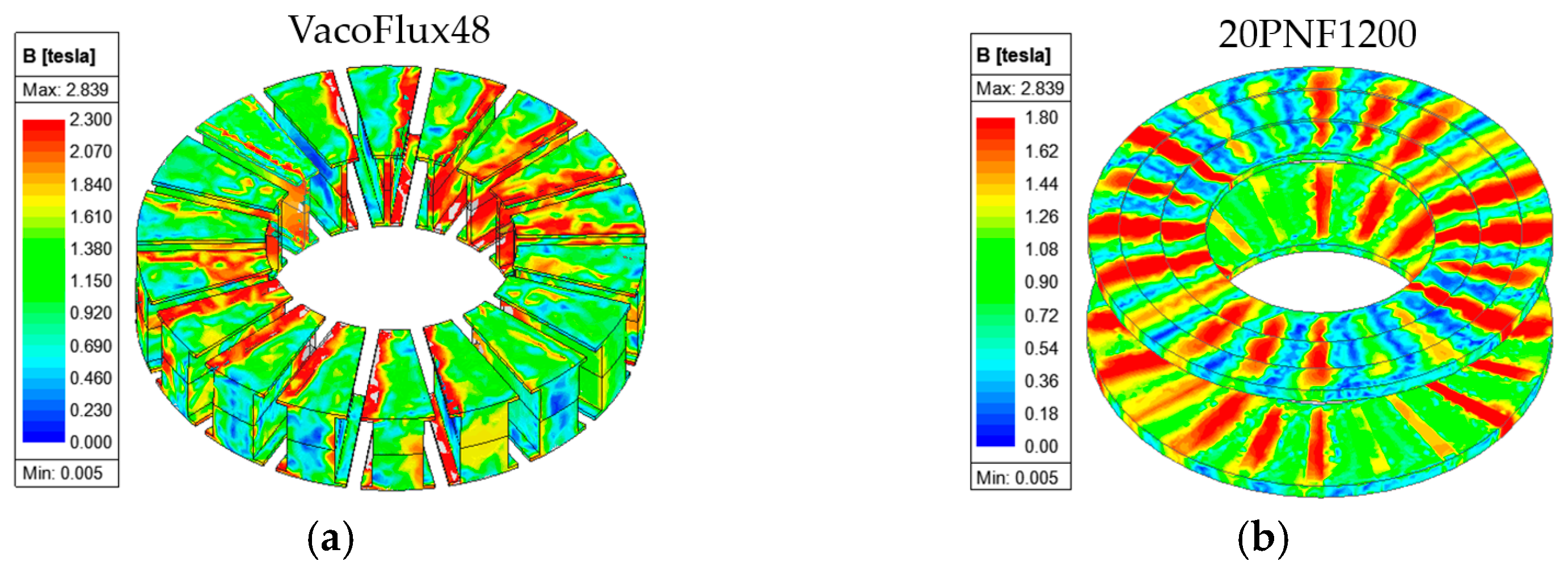
| Material | Stator core | VacoFlux 48 | |
| Rotor core | 20PNF1200 | ||
| Permanent magnet | N45UH | ||
| Copper | Copper | ||
| Stator hub/housing | Aluminum | ||
| Cooling system | Cooling type | Forced liquid (water) | |
| Liter per minute (LPM) | 8 | ||
| Description | Rated Point | Peak Point | |||||
|---|---|---|---|---|---|---|---|
| Sim. | Exp. | Sim. | Exp. | ||||
| PM segmentation | 1 Seg. | 7 Seg. | 7 Seg. | 1 Seg. | 7 Seg. | 7 Seg. | |
| Output power (kW) | 78.99 | 80.85 | 75.53 | 105.9 | 110.5 | 103.7 | |
| Output torque (Nm) | 419 | 429 | 401 | 562 | 586 | 552 | |
| Rotational speed (rpm) | 1800 | 1800 | 1800 | 1800 | 1800 | 1800 | |
| Current (Arms) | 172 | 172 | 172 | 240 | 240 | 240 | |
| Current density (Arms/mm2) | 17.5 | 17.5 | 17.5 | 24.4 | 24.4 | 24.4 | |
| Efficiency (%) | 93.38 | 94.84 | 94.61 | 90.57 | 92.73 | 92.57 | |
| Torque ripple (%) | 4.99 | 5.27 | - | 4.76 | 4.71 | - | |
| Power factor | 0.829 | 0.833 | - | 0.760 | 0.738 | - | |
| Total loss (W) | 5601 | 4403 | - | 10968 | 8665 | - | |
| Losses (W) | Iron core | 340 | 400 | - | 586 | 676 | - |
| DC copper | 941 | 941 | - | 1831 | 1831 | - | |
| AC copper * | 941 | 941 | - | 2380 | 2380 | - | |
| Solid (stator hub and PM) | 2985 | 1717 | - | 5641 | 3225 | - | |
| Mechanical ** | 395 | 395 | - | 530 | 553 | - | |
| Description | Stator Core Materials | |||
|---|---|---|---|---|
| Non-Oriented Steel (VacoFlux48) | Grain-Oriented Steel (23PHD085) | SMC (SMC700) | ||
| PM segmentation | 1 Seg. | 1 Seg. | 1 Seg. | |
| Output power (kW) | 78.99 | 75.4 | 69.3 | |
| Rotational speed (rpm) | 1800 | 1800 | 1800 | |
| Output torque (Nm) | 419 | 400 | 367 | |
| Torque ripple (%) | 4.99 | 7.07 | 5.81 | |
| Power factor | 0.829 | 0.828 | 0.876 | |
| Current (Arms) | 172 | 172 | 172 | |
| Current density (Arms/mm2) | 17.5 | 17.5 | 17.5 | |
| Efficiency (%) | 93.38 | 93.10 | 92.59 | |
| Total loss (W) | 5601 | 5588 | 5549 | |
| Losses (W) | Iron core | 340 | 465 | 771 |
| DC copper | 941 | 941 | 941 | |
| AC copper * | 941 | 941 | 941 | |
| Solid (stator hub and PM) | 2985 | 2864 | 2549 | |
| Mechanical ** | 395 | 377 | 347 | |
| Cost | Very high | Moderate | High | |
| Performance | Very high | High | Low | |
| Manufacturability (mass production) | Low | Low | Very high | |
| Description | Stator/Rotor Core Materials | ||
|---|---|---|---|
| 23PHD085/20PNF1200 | 23PHD085/23PHD085 | ||
| PM segmentation | 1 Seg. | 1 Seg. | |
| Output power (kW) | 75.4 | 74.38 | |
| Rotational speed (rpm) | 1800 | 1800 | |
| Output torque (Nm) | 400 | 394.6 | |
| Torque ripple (%) | 7.07 | 8.07 | |
| Power factor | 0.829 | 0.829 | |
| Current (Arms) | 172 | 172 | |
| Current density (Arms/mm2) | 17.5 | 17.5 | |
| Efficiency (%) | 93.10 | 93.10 | |
| Total loss (W) | 5588 | 5551 | |
| Losses (W) | Iron core | 465 | 531 |
| DC copper | 941 | 941 | |
| AC copper * | 941 | 941 | |
| Solid (stator hub and PM) | 2864 | 2766 | |
| Mechanical ** | 377 | 372 | |
| Description | SPM Array Type | HPM Array Type | IHPM Array Type | ||||
|---|---|---|---|---|---|---|---|
| Stator core material | VacoFlux48 | ||||||
| Rotor core material | 20PNF1200 | ||||||
| PM segmentation | 1 Seg. | 7 Seg. | 1 Seg. | 5 Seg. | 1 Seg. | 5 Seg. | |
| PM thickness (mm) | 7 | 7 | 7 | 7 | 11 | 11 | |
| Number of turns | 27 | 27 | 27 | 27 | 23 | 23 | |
| Output power (kW) | 78.99 | 80.85 | 86.67 | 87.23 | 81.97 | 82.32 | |
| Rotational speed (rpm) | 1800 | 1800 | 1800 | 1800 | 1800 | 1800 | |
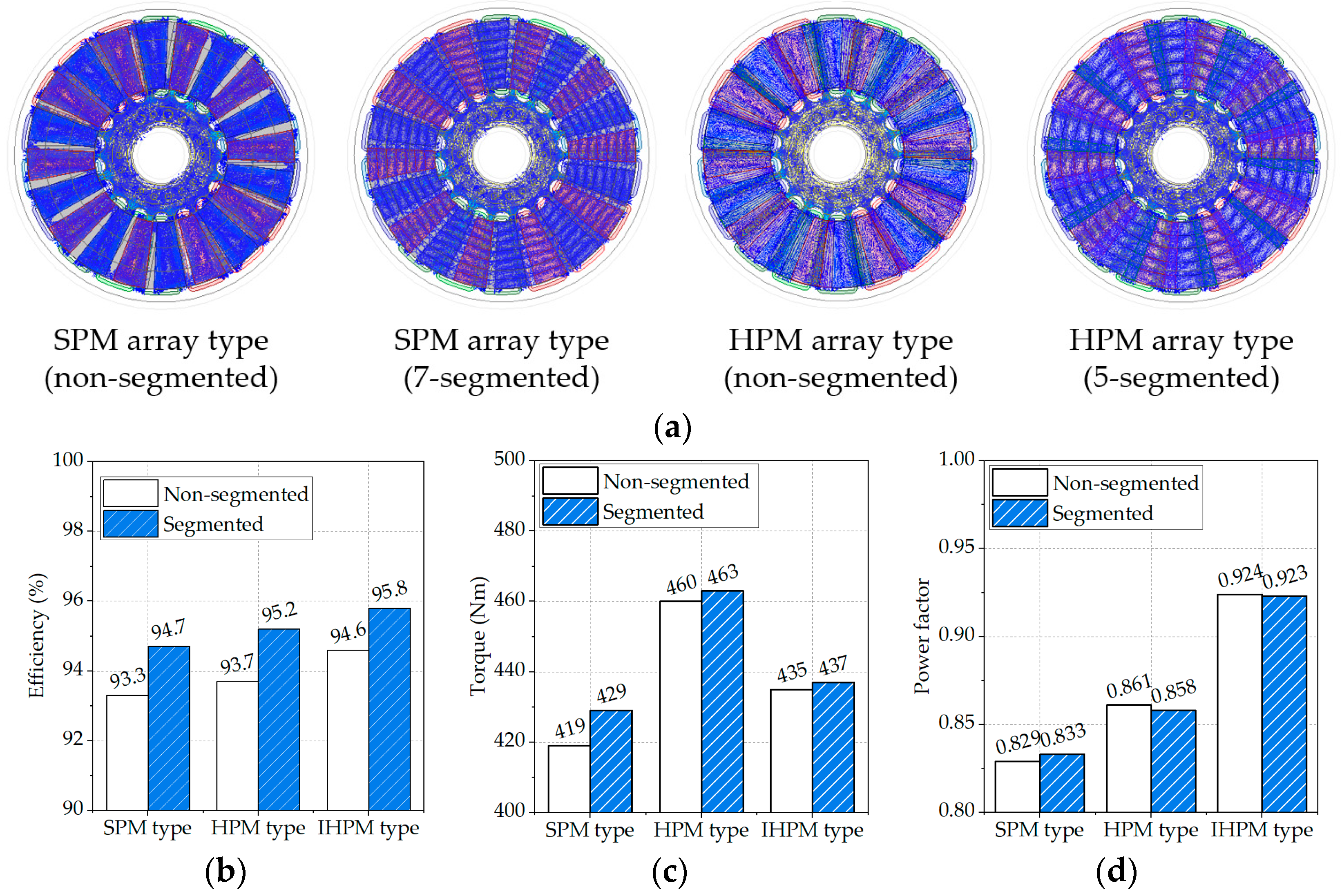
| Output torque (Nm) | 419 | 429 | 460 | 463 | 435 | 437 | |
| Torque ripple (%) | 4.99 | 5.27 | 6.7 | 5.69 | 6.88 | 6.99 | |
| Power factor | 0.829 | 0.833 | 0.861 | 0.858 | 0.924 | 0.923 | |
| Current (Arms) | 172 | 172 | 172 | 172 | 172 | 172 | |
| Current density (Arms/mm2) | 17.5 | 17.5 | 17.5 | 17.5 | 17.5 | 17.5 | |
| Efficiency (%) | 93.38 | 94.84 | 93.77 | 95.21 | 94.34 | 95.06 | |
| Total loss (W) | 5602 | 4403 | 5761 | 4393 | 4919 | 4277 | |
| Losses (W) | Iron core | 340 | 400 | 653 | 666 | 583 | 587 |
| DC copper | 941 | 941 | 941 | 941 | 801 | 801 | |
| AC copper * | 941 | 941 | 941 | 941 | 801 | 801 | |
| Solid (stator hub and PM) | 2985 | 1717 | 2793 | 1409 | 2044 | 1396 | |
| Mechanical ** | 395 | 404 | 433 | 436 | 410 | 412 | |
Disclaimer/Publisher’s Note: The statements, opinions and data contained in all publications are solely those of the individual author(s) and contributor(s) and not of MDPI and/or the editor(s). MDPI and/or the editor(s) disclaim responsibility for any injury to people or property resulting from any ideas, methods, instructions or products referred to in the content. |
© 2023 by the authors. Licensee MDPI, Basel, Switzerland. This article is an open access article distributed under the terms and conditions of the Creative Commons Attribution (CC BY) license (https://creativecommons.org/licenses/by/4.0/).
Share and Cite
Hong, D.-K.; Park, J.-H.; Jeong, Y.-H. Comprehensive Analysis of Dual-Rotor Yokeless Axial-Flux Motor with Surface-Mounted and Halbach Permanent Magnet Array for Urban Air Mobility. Energies 2024, 17, 30. https://doi.org/10.3390/en17010030
Hong D-K, Park J-H, Jeong Y-H. Comprehensive Analysis of Dual-Rotor Yokeless Axial-Flux Motor with Surface-Mounted and Halbach Permanent Magnet Array for Urban Air Mobility. Energies. 2024; 17(1):30. https://doi.org/10.3390/en17010030
Chicago/Turabian StyleHong, Do-Kwan, Jang-Hyun Park, and Yeon-Ho Jeong. 2024. "Comprehensive Analysis of Dual-Rotor Yokeless Axial-Flux Motor with Surface-Mounted and Halbach Permanent Magnet Array for Urban Air Mobility" Energies 17, no. 1: 30. https://doi.org/10.3390/en17010030