Article

Comprehensive Analysis of Dual-Rotor Yokeless Axial-Flux Motor with Surface-Mounted and Halbach Permanent Magnet Array for Urban Air Mobility

1
Electric Machine and Drive System Research Center, Korea Electrotechnology Research Institute (KERI), Changwon 51543, Republic of Korea
2
Electric Energy Conversion Engineering, University of Science and Technology, Changwon 51543, Republic of Korea
*
Author to whom correspondence should be addressed.
Energies 2024, 17(1), 30; https://doi.org/10.3390/en17010030
Submission received: 3 December 2023 / Revised: 18 December 2023 / Accepted: 18 December 2023 / Published: 20 December 2023
(This article belongs to the Section F: Electrical Engineering)

Abstract

:
A dual-rotor yokeless and segmented armature (YASA)-type axial-flux permanent magnet (AFPM) motor with a surface-mounted permanent magnet (SPM) array type was developed for urban air mobility (UAM) aircraft in this work. The proposed AFPM motor had rated and peak output powers of 75.5 and 104 kW, respectively, with rated and peak rotational speeds of 1800 rpm. To achieve a high torque, a cobalt–iron alloy core material was used for the stator core. The prototype AFPM motor, developed by KSEP in the Republic of Korea, was successfully manufactured and verified through experimentation. Additionally, the thermal stability of the winding and permanent magnets (PMs) was confirmed with a water-cooling system. A structure analysis of the proposed AFPM motor was conducted due to the detachment of an uneven air-gap length in the prototype AFPM motor. An output performance comparison based on core materials for the stator and rotor was carried out to explore the material cost reduction. Subsequently, the design for performance improvement by applying a Halbach permanent magnet (HPM) array type was investigated for further research.

1. Introduction

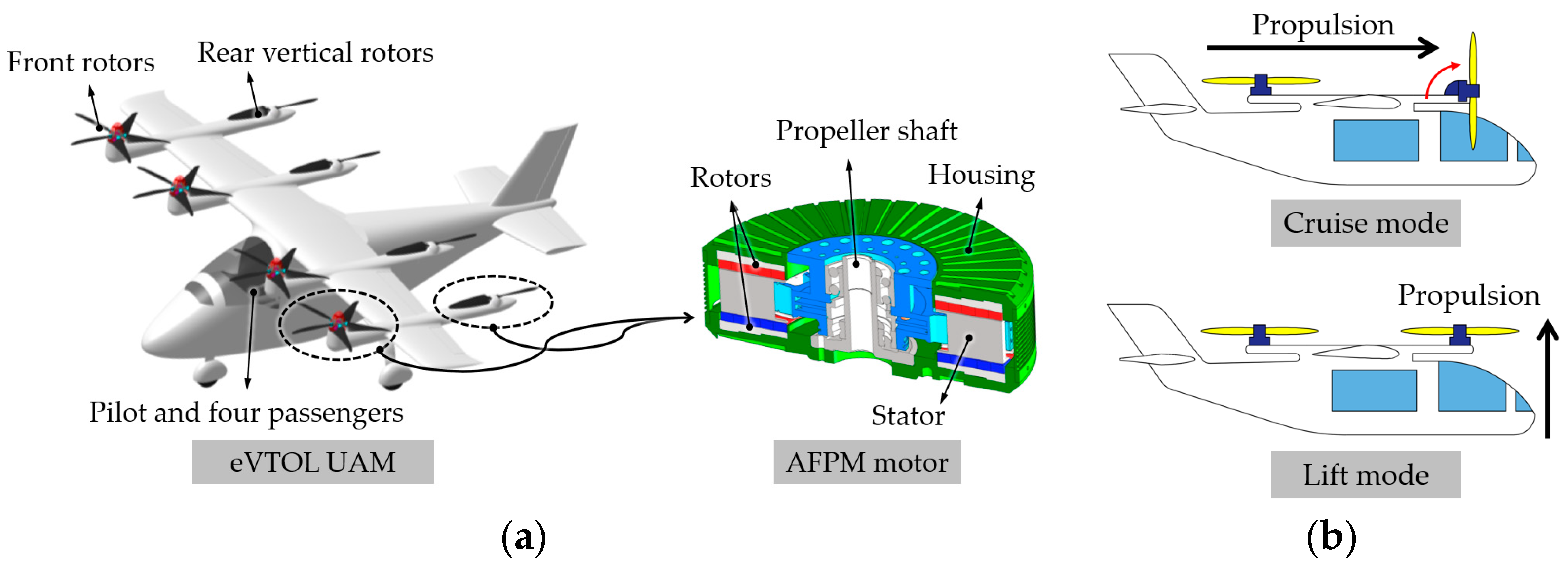
Recently, the electrification of traction systems has gained attention as a method of reducing greenhouse gases. In the aviation industry, the use of UAM aircraft is considered a good alternative as a quick public transportation option with fewer greenhouse gas (GHG) emissions and low noise. In UAM aircraft, a distributed electric propulsion system is generally used, as shown in Figure 1a. The electric motors are placed at the front and rear rotors and are combined with each propulsion propeller. The distributed electric propulsion system for UAM offers noise reduction, improved efficiency, fuel saving, and improved stability [1]. Another distinctive feature of UAM aircraft is the capability of vertical landing and take-off (VTOL) from the lift mode, as shown in Figure 1b [2]. Therefore, UAM vehicles can be an alternative to helicopter services in urban areas. In the cruise mode, as shown in Figure 1b, the front rotors are rotated to the horizontal propulsion direction.
The AFPM motor is a strong candidate due to its high torque density in comparison to conventional radial-flux permanent magnet (RFPM) motors [3,4,5,6]. AFPM motor topologies are mainly classified as shown in Figure 2 [7]. A lightweight design is important to save fuel and extend flight times in the aviation industry [8,9]. Direct-drive propulsion without a mechanical-reduction gear system was selected in this work. For this reason, a high-torque-density AFPM motor topology was considered.
Figure 1. VTOL UAM aircraft system: (a) with dual-rotor yokeless AFPM motor and (b) cruise and lift modes.
Energies 17 00030 g001
Among AFPM motor topologies (Figure 2), the double-sided internal rotor (AFIR) and double-sided internal stator (TORUS) types exhibit a higher torque density compared to the single-sided structure [7,10]. While a multi-staged structure can achieve a higher torque density than other structure types, it features a more complex structure than double-sided structures [11,12]. Consequently, the AFIR and TORUS types of AFPM motors are considered to be the best candidates for achieving a high torque density.
It has been suggested that the TORUS type has the highest power density and efficiency compared to other AFPM structures [7]. Another study [13] showed that the power density of the AFIR and TORUS types depended on the current density and electrical loadings, which means that the power density is contingent on the design approach method. However, there are clear structural differences between the AFIR and TORUS types. The AFIR type has a greater heat dissipation capacity compared to the TORUS type, as illustrated in Figure 3b, due to its stator being connected with the housing part, as illustrated in Figure 3a. The TORUS-type AFPM motor has two different PM arrangements, which are the N-N and N-S types, as shown in Figure 3b,c. The flux loop of the TORUS N-N type passes through the stator back yoke; thus, the yoke thickness should be adjusted to reduce the core loss generated from magnetic flux saturation.
However, compared to the TORUS N-N types, the flux loop of the TORUS N-S type does not pass through the stator back yoke. Therefore, the stator yoke core of the TORUS N-S type can be eliminated and, thus, the motor axial length can be reduced, which leads to a high power-to-weight ratio (kW/kg). Finally, the stator back yoke can be removed, as shown in Figure 3d. This structure is called the YASA type [14]. By removing the stator back yoke, the stator is constructed as a segmented structure, and a high fill factor and short end windings are feasible. Therefore, a YASA-type AFPM motor can reduce not only the core loss, but also the copper loss, which improves efficiency.
Figure 3. The structures of AFIR and TORUS AFPM motors: (a) AFIR type, (b) TORUS N-N type, (c) TORUS N-S type, and (d) YASA type (yokeless TORUS type).
Energies 17 00030 g003
The YASA-type AFPM motor has an outstanding performance compared to other AFPM motors [15,16,17]. Previous findings have revealed that the power factor (PF) of the YASA type is higher than that of the single-sided type [15]. Another study showed that the YASA type was more suitable for achieving a high torque density with a high current density than the single-sided type [16]. This was due to the lower flux density saturation in the stator core compared to the single-sided type. Yet another study found that the torque density of the YASA-type configuration with the factional slot concentrated winding (FSCW) type was higher than that of the integral slot distributed winding (ISDW) type [17]. However, the efficiency of the FSCW type was lower than that of the ISDW type. To achieve a high torque density, a YASA-type AFPM motor with the FSCW type was considered in this work.
The design of the PM arrangement on the rotor can enhance the output performance of a motor. Compared to the SPM array type, as shown in Figure 4a, the HPM array type (Figure 4b) exhibited a significantly increased back-electromagnetic force (EMF), resulting in an improved output torque [18,19]. Previous research has shown that the torques of coreless HPM-array-type rotor AFPM motors are increased by 43% and 50%, respectively, compared to SPM-array-type rotor AFPM motors [18,19]. One study examined an axial–radial PM Halbach-array-type AFPM motor [6], which had a high torque compared to Halbach-array-type AFPM and RFPM motors, while another indicated that the HPM array type had a 28% higher torque than that of the spoke array type [20]. Other studies [21,22] have found that the torque performance can be further improved by adjusting the main and auxiliary pole angles of the HPM array type, as shown in Figure 4b.
In this work, a dual-rotor YASA-type AFPM motor with a cobalt–iron alloy core and an SPM array type was verified with experimentation for the rated and peak output power points. The measured output performance values were in the acceptable range compared to the simulation results. The increases in the temperature for continuous operation at the rated and peak output power points were measured, and the thermal stability was successfully verified. However, an uneven air-gap length was confirmed for the prototype AFPM motor. This phenomenon was analyzed using a structure analysis while considering electromagnetic and centrifugal forces based on an electromagnetic–mechanical coupled analysis.
A cobalt–iron alloy core achieves torque density from the high saturation level of the magnetic flux density, compared to general silicon–iron alloy cores [23]. However, its cost is significantly higher than that of other core materials, such as a silicon–iron alloy core or a soft magnetic core. Therefore, an output performance comparison to the proposed AFPM motor according to the core materials for the stator and rotor was carried out to investigate an alternative core material. After that, the proposed AFPM motor with an HPM array was analyzed for improving the output performance.
The distinctiveness of this paper lies in the following aspects:
(1)
The development of an AFPM motor faces challenges such as its manufacturability, thermal stability, structural deformation, noise, and vibration. In this paper, the designed dual-rotor YASA-type AFPM motor with a cobalt–iron alloy core was manufactured. The prototype AFPM motor was successfully validated for its rated and maximum output power. Furthermore, its thermal stability was verified through experiments under cooling conditions with a water jacket system. Therefore, the design specifications presented in this work can serve as a reference for AFPM motor design.
(2)
It is noteworthy that the comparison results, according to the core materials for the stator and rotor, showed that grain-oriented electrical steel with a silicon–iron alloy core can be an alternative to a cobalt–iron alloy core material, as the output torque decreases slightly.

2. Sizing Equation for AFPM Motor Design

The general-purpose sizing equation for the AFPM machines P R (W) from [24] is expressed as follows:
P R = 1 1 + K ϕ m m 1 π 2 B g A f p η K e K i K p K L 1 λ 2 1 + λ 2 D o 2 L e
K i = I p k I r m s ,   K p = 1 T 0 T e ( t )   i ( t ) E pk   I p k d t ,   K L = D o L e ,   A s = 2 m 1 N I r m s π D g ,   λ = D o D i
where K ϕ = A r / A s is the ratio of electric loadings on rotor and stator (dimensionless), m is the number of phases (dimensionless), m 1 is the number of phases for each stator (if there is more than one stator, each stator has the same m 1 ) (dimensionless), B g is the air-gap flux density (T), A =   A s + A r is total electric loading (Arms/m), f is the electrical frequency (Hz), p is the number of pole pairs (dimensionless), η is the efficiency (%), K e is the winding factor (dimensionless), D o is the outer diameter of the machine (m), L e is the effective stack length of the machine (m), K i is the crest factor (dimensionless), K p is the electrical power waveform factor (dimensionless), K L is the ratio of outer diameter to the effective stack length of the AFPM machine (dimensionless), A s is the stator electrical loading (Arms/m), λ is the ratio of inner to output surface diameters (dimensionless), I p k is the peak phase current (Apeak), I rms is the root-mean-squared phase current (Arms), e(t) is the phase back-EMF (V), i(t) is the phase current (A), Epk is peak phase back-EMF (Vpeak), N is the number of turns per phase (dimensionless), D g is the average diameter of air gap (m), and D i is the inner diameter of the machine (m).
The average electromagnetic torque equation for TORUS-type AFPM machines T e (Nm) can be expressed as [7,24]:
T e = π 4 K i K p B g A s 1 λ 2 1 + λ 2 D o 3
As indicated in Equations (1)–(3), designing AFPM machines requires adjusting various parameters. The design of the term of the ratio of the inner to the output surface diameters λ for Equations (1) and (2) is important for achieving the required specifications and taking the restricted volume of the AFPM machine system into account. Moreover, the other parameters, such as the electrical and magnetic loadings and the air-gap flux density, should be appropriately determined. Different core materials, shapes of the stator and rotor, and PM arrays affect the ratio of electric loadings on the rotor and stator K ϕ , the air-gap flux density B g , the total electrical loading A , and the electrical power waveform factor K p .

3. Analysis and Experimental Validation of the Proposed AFPM Motor with SPM Array

3.1. Required Design Specifications

The proposed AFPM motor (EPM310) with an SPM array was developed by KSEP in Miyang-si, Gyeongsangnam-do, the Republic of Korea [25]. The required design specifications of the proposed AFPM motor for UAM, with an output power rating of 100 kW and a power-to-weight ratio of 3 kW/kg, are listed in Table 1. The performance design was divided into rated and peak output powers. To meet the high-power demands during the lift mode, as illustrated in Figure 1b, a lifting power beyond the rated output power was required.
The structure of the proposed AFPM motor, as shown in Figure 5, employed a 20-pole 18-slot configuration. The segmented stator cores were supported by the stator hub. The proposed AFPM motor system incorporated a cooling system installed in the stator hub. The housing was attached to the rotor, which was connected to the shaft of the propeller. To withstand axial loads, angular-contact ball bearings were adopted. The thermal stability of the AFPM motor with cooling for the UAM system was analyzed using computation fluid dynamics (CFD) [26,27,28].
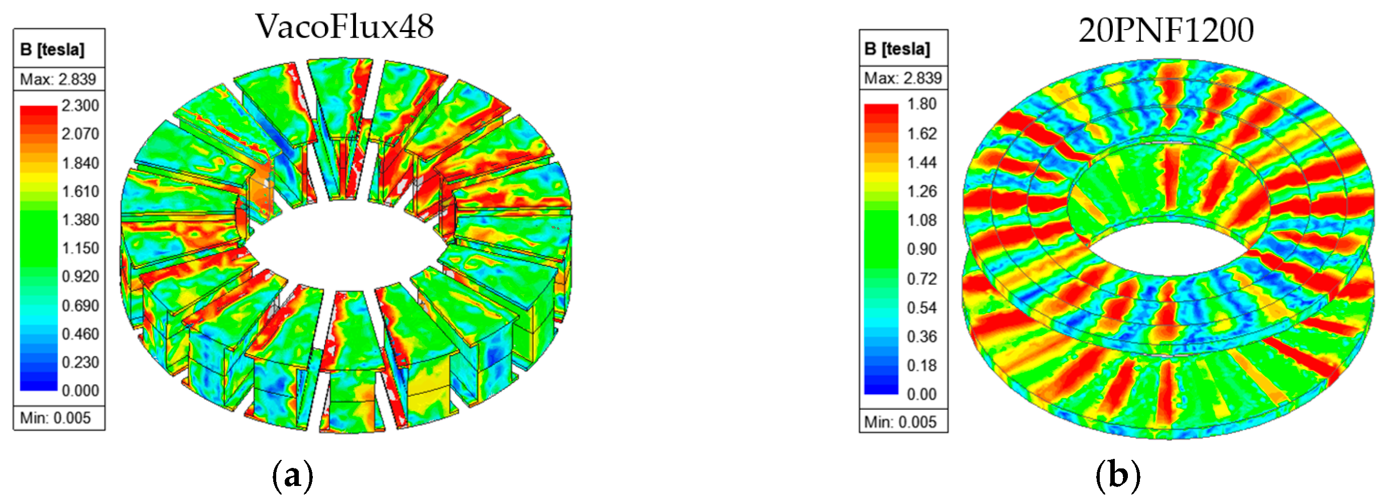
For the three-phase winding with a wye (star) connection, the proposed model utilized circular-wound conductors with 54 turns per slot, arranged in two layers with two parallel connections per phase. To achieve the desired power-to-weight ratio, an iron–cobalt-alloy-type core (VacoFlux48) was selected for the stator. In the case of the rotor, silicon electrical steel (20PNF1200) was considered. Considering the high current, a liquid water-cooling system providing 8 L per minute (LPM) was incorporated into the proposed AFPM motor system. The material of the PM was selected in the UH grade with a temperature rating of 180 °C, specifically in the N45 grade. To reduce the PM eddy current loss, the PMs were divided into seven segmentations. The other geometric parameters are listed in Table 1. The AFPM motor was verified through a performance analysis and experimentation. The total weight, including the motor’s active part, the stator support hub, the cooling system, and the housing, was 35.6 kg.
Figure 5. Structure of proposed AFPM motor.
Energies 17 00030 g005

3.2. Experimental Validation

3.2.1. Experimental Setups

The experiment to verify the prototype AFPM motor was conducted through iron bird and dynamo tests, together, as shown in Figure 6. The iron bird test, as shown in Figure 6a, refers to a ground-based test for a prototype UAM system with the propeller load. Water cooling was applied during the experiments, taking into account practical application situations. To obtain the required performance results at both the rated and peak output powers, a motor dynamo test was conducted using the motor dynamo test setup, as shown in Figure 6b, and the measured results are listed in Table 2.

3.2.2. Measured Results Analysis

The PMs of the prototype AFPM motor were segmented, as shown in Figure 5, because the overall output performances were improved compared to the single-PM segmentation listed in Table 2. The measured output torque at the required current values was 4.52% lower at the rated point and 2.30% lower at the peak compared to the simulation results. The efficiency η of the electric motors was calculated as follows:
η = P o u t P i n = P o u t P o u t + P c o r e + P D C + P A C + P s o l i d + P m e c h  
where P i n , P o u t , P c o r e , P D C , P A C , P s o l i d , and P m e c h denote the input power (W), output power (W), iron core loss (W), DC copper loss (W), AC copper loss (W), solid loss (eddy current loss) (W), and mechanical loss (W).
In the simulation analysis and design stage, the iron core, DC copper, solid, and assumed mechanical losses were only considered for calculating the efficiency. A mechanical loss of 0.5% of the output power was assumed. The measured efficiency was 1.28% lower at the rated point and 2.06% lower at the peak point compared to the simulation results without AC copper loss. The prototype AFPM motor was estimated to have a quite high AC copper loss.
The AC/DC copper loss ratio depends on various parameters, such as the number of turns, the wire diameter, the wire location, and the external flux density, which is passed through the wire [29,30]. Analyzing the AC copper loss using a simulation consumes a significant amount of computational time due to the complex 3D modeling [29,31]. Moreover, the thermal stability was experimentally examined through a continuous operation, as presented in Section 3.2.3. For this reason, the AC copper loss of the rated and peak output powers was estimated, taking into account the reduced efficiency between the experimental and simulation results. The AC/DC copper loss ratios of the rated and peak output powers were 1.00 and 1.30, respectively. The simulation efficiency, considering the estimated AC copper loss, is listed in Table 2.
The magnetic flux saturation distribution of the stator and rotor cores is shown in Figure 7a,b. The saturation point of the stator core material VacoFlux48 was 2.3 T, while the saturation point of the stator core 20PNF1200 was 1.8 T. It was noted that the PMs and stator hub exhibited high eddy current losses, as listed in Table 2. The eddy current density vector distribution is shown in Figure 8.

3.2.3. Measurement of Temperature Rises of PM and Windings

Ensuring thermal stability in the winding PMs is important due to their limited temperature range (winding = 220 °C and PM = 180 °C). To address this, the temperature rise on the winding was measured during the continuous operation at both the rated and peak output powers. Figure 9 shows the temperature rises on the winding. In the case of continuous operation at the rated output power, a maximum temperature of the winding of 161 °C was measured after one hour of operation. Compared to the temperature rise of the rated output power, as shown in Figure 9a, the temperature of the peak output power as shown in Figure 9b increased dramatically due to the high current density. The temperature of the PMs was measured after halting the continuous operation due to the PMs being rotated during operation, which means that a thermocouple sensor could not be attached. The measured temperatures of the PM of the rated and peak output powers were 100 °C and 120 °C, respectively.

3.3. Air-Gap Length Deformation Analysis (Structure Analysis)

Unlike an RFPM motor, an AFPM motor can generate an uneven air-gap length due to the structural deformation caused by the electromagnetic and centrifugal forces in the rotating disc-shaped rotor. The disc-shaped rotor caused the prototype AFPM motor to have an uneven air-gap length. For this reason, the deformation phenomenon was analyzed using a structure analysis with an electromagnetic–mechanical coupled analysis.
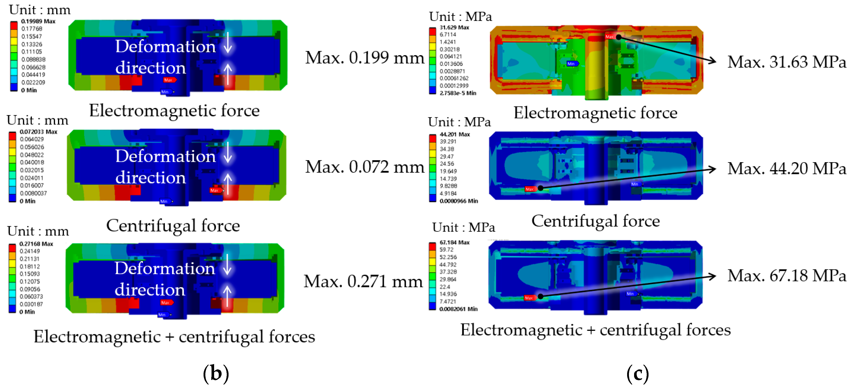
This uneven air gap can lead to significant deformations, potentially causing interference or friction between the stator and rotor. Therefore, to address the structural deformation issue caused by electromagnetic and centrifugal forces, the proposed AFPM motor with an air-gap length of 1.5 mm was analyzed using a structure analysis for the rotor’s position, where the maximum electromagnetic forces are created.
Although the maximum rotational speed of the proposed AFPM motor was 1800 rpm, a rotational speed of 2800 rpm was considered, taking the worst outcome into account. The electromagnetic force, calculated using an electromagnetic analysis, was mapped on the surface of the PM, as shown in Figure 10a. Figure 10b shows the deformations from magnetic and centrifugal forces. The deformation generated from the electromagnetic force was much larger than that of the centrifugal force. By adding magnetic and centrifugal forces, a total deformation of 0.271 mm was generated. Therefore, the prototype AFPM motor had an uneven air-gap length. A maximum stress of 67.18 MPa occurred on the PM.

4. Electromagnetic Performance Analysis of Proposed AFPM Motor with SPM Array According to Stator Core Materials to Reduce Cost

The appropriate selection of core materials is one of the methods for improving the performance of a motor. The iron–cobalt alloy core VacoFlux48, which is a non-oriented electrical steel, applied to the prototype AFPM motor, as shown in Figure 5 and Figure 6, was selected for the stator core to achieve a high torque density. However, this iron–cobalt alloy core is expensive compared to other core materials, such as grain-oriented electrical steel or an iron–silicon-alloy-type core of non-oriented electrical steel. To alternate the iron–cobalt alloy core for the stator and core, the electromagnetic performances using grain-oriented electrical steel and soft magnetic composite (SMC) materials were investigated in this work.
The B-H curves of the selected materials of non-oriented electrical steel (VacoFlux48 and 20PNF1200), grain-oriented electrical steel (23PHD085), and SMC (SMC700) are shown in Figure 11.
The 23PHD085 material had two different B-H curves according to the rolling direction (RD) and the transverse direction (TD), as shown in Figure 11. It is difficult to apply an RFPM motor to grain-oriented electrical steel due to the motor’s need for segmented stator cores. On the other hand, a YASA-type AFPM motor can be applied to grain-oriented electrical steel only as a stator material. However, due to the complex and different cross-section of the stator core, the motor requires multiple molds for casting in the manufacturing process. An SMC can overcome the manufacture complex of the grain-oriented electrical steel because it is possible to freely create the desired core shape with molds, and as a result, mass production is possible.

4.1. Performance Comparison According to Core Materials for Stator

The electromagnetic performance comparison of different stator core materials is listed in Table 3. The AC copper loss was estimated based on the deviation analysis between the simulation and the experiment in Section 3.2.2. The rotor core material of 20PNF1200 was fixed in this analysis. The output torques of 23PHD085 and SMC700 were 4.7% and 14.2% lower, respectively, compared to VacoFlux48. The PF of SMC700 was the highest out of all the other materials. However, to achieve a high torque, SMC700 was not appropriate. 23PHD085 can be used as an alternative to Vacoflux48 due to the torque being slightly low. However, the torque ripple of 23PHD085, mainly considering the rolling direction, was higher than when other materials were applied. The increased torque ripple can be reduced through a shape design; thus, 23PHD085 could replace VacoFlux48 to reduce the cost.
Table 4 shows the performance comparison with different rotor core materials. 23PHD085 was selected for the stator core material. The AC copper loss was estimated based on the deviation analysis between the simulation and the experiment in Section 3.2.2. It was clear that 20PNF1200 for the rotor core was more useful due to its higher torque and lower torque ripple when compared to applying 23PHD085 for the rotor core. The efficiencies were similar. In addition, since 20PNF1200 is more cost effective than 23PHD085, it is reasonable to select 20PNF1200 as the rotor core material.

5. Performance Improvement Design of the Proposed AFPM Motor with HPM Array
As described in Section 4.1, a study on the performance comparison of different core materials was conducted. The appropriate selection of core materials improves the output performance and reduces the material cost of the AFPM motor. In this section, a performance improvement design involving applying an HPM array type, as shown in Figure 4, to the proposed AFPM motor designed with the SPM array type was presented and compared with the SPM array type. The HPM array type, which concentrated the magnetic flux in the air gap, enhanced the output performances by improving back-EMF compared to the SPM array type.
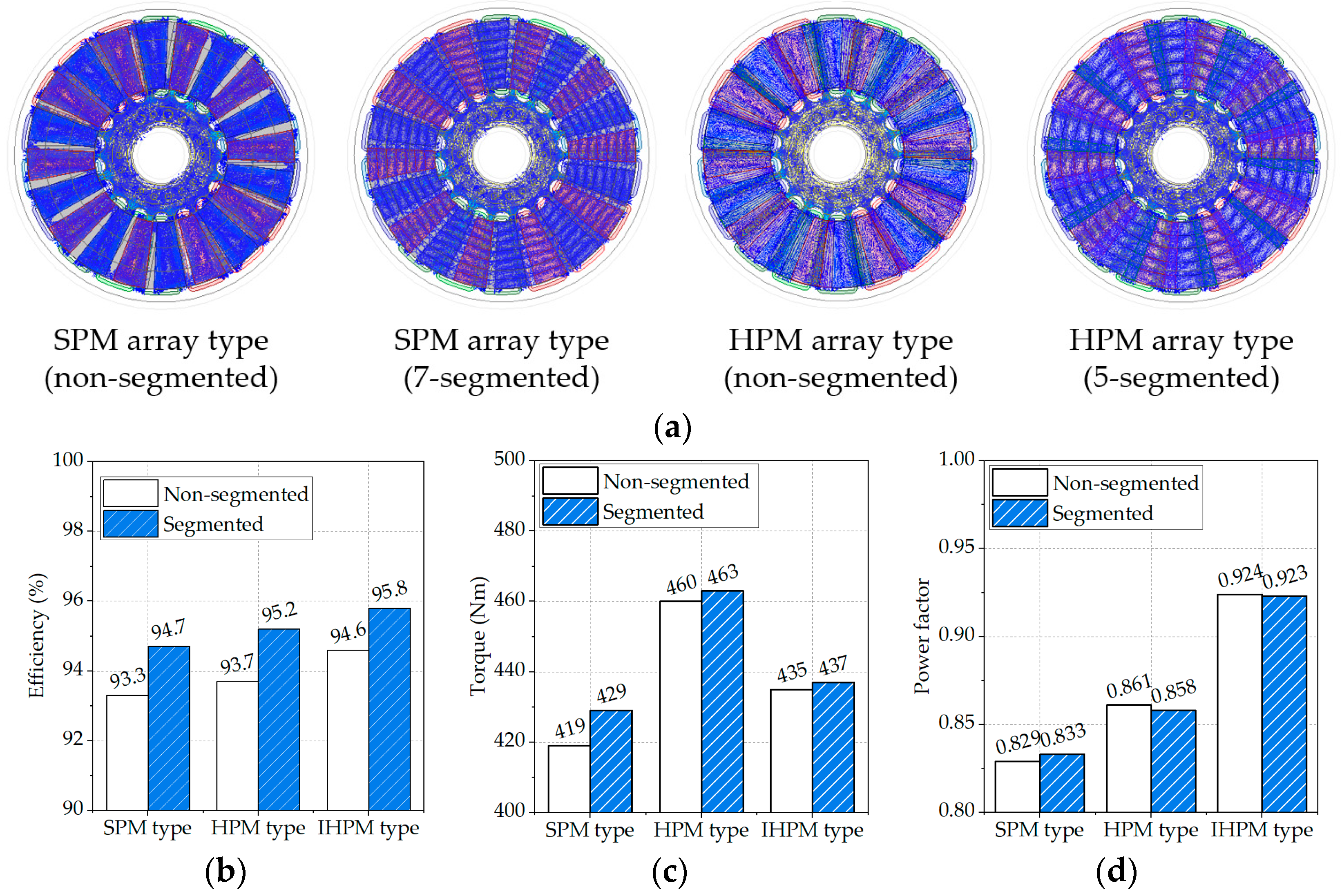
Figure 12a shows the eddy current loss distributions of the stator hub and the PM of the SPM and HPM array types. To reduce the eddy current loss of the stator hub and the PM, the PMs of the SPM and HPM array types were segmented to five and seven segmentations, respectively. By reducing the eddy current losses, the efficiency was improved significantly, as shown in Figure 12b. Adjusting the Halbach pole ratio of the main and auxiliary angles [21,22], as shown in Figure 4, can improve the output performances. The Halbach pole ratio of the proposed AFPM motor, which was 7:3 (main and auxiliary angles), was determined after analyzing the Halbach pole ratios of 5:5, 6:4, and 8:2.
A comparison of the main output performances of the SPM and HPM array types is presented in Figure 12b–d. An improvement design of PF by adjusting the number of turns as electrical loading and the PM thickness as magnetic loading was conducted. This model was named the improved HPM (IHPM) array type. The detailed output performance analysis results are listed in Table 5. The AC copper loss was estimated based on the deviation analysis between the simulation and the experiment in Section 3.2.2. The overall output performances of the HPM array type were improved compared to the SPM array type. In particular, the output torque of the HPM array type was 7.92% higher than that of the SPM array type.
Figure 12. (a) Eddy current loss distributions of stator hub and PM, (b) efficiency comparison, (c) torque comparison, and (d) power factor comparison.
Energies 17 00030 g012
Improving the PF is important for reducing the capacity and the cost of the inverter. Although the PF of the HPM array type was improved slightly, as shown in Figure 12d, it was still a low value. High electrical loading leads to a reduction in the PF from the increased reactance component. Therefore, the number of turns of the IHPM array type was changed to 23 from 27 to reduce the electrical loading. Compared to the SPM array type, the HPM array type exhibited a decreased magnetic flux loop to the rotor yoke. The PM thickness of the IHPM array type was increased from 7 to 11 mm to compensate for the decreased electrical loading, while simultaneously reducing the back yoke thickness of the rotor by 4mm. By adjusting the electrical and magnetic loadings, the PF of the IHPM array type was increased from 0.858 to 0.923 compared to the HPM array type, as shown in Figure 12d. The number of turns of the IHPM array type was lower than that of the SPM and HPM array types. This suggests that the copper had more available area, which meant that a larger-diameter wire could be used. Therefore, the current density of the winding was reduced, and the thermal stability was secured.

6. Conclusions

A dual-rotor YASA-type AFPM motor with an SPM array type was presented for UAM with a distributed electric propulsion system in this work. To achieve a high power-to-weight ratio, an iron–cobalt alloy core (VacoFlux48) was applied. The prototype AFPM motor, developed by KSEP in the Republic of Korea, was successfully verified. However, the prototype AFPM motor exhibited an uneven air-gap length due to the deformation of the rotor resulting from electromagnetic and centrifugal forces. In the future, an improved design to minimize rotor deformation will be conducted to mitigate the uneven air-gap length.
While an iron–cobalt alloy core achieves a high power-to-weight ratio, it is relatively expensive. Therefore, the electromagnetic characteristics of the proposed AFPM motor were compared based on various core materials, including an iron–cobalt alloy core (VacoFlux48), iron–silicon alloy cores (20PNF1200 and 23PHD085), and a soft magnetic core (SMC700), for the stator and rotor. It was confirmed that 23PHD085 for the stator can replace VacoFlux48 due to the torque decreasing slightly by 4.7%. Therefore, 23PHD085 could serve as a cost-effective alternative to the relatively expensive VacoFlux48. Subsequently, to achieve a higher torque density and power factor compared to the proposed AFPM motor with the SPM array type, an HPM-array-type AFPM motor was designed. In the future, a YASA-type AFPM motor with an HPM array type, which was reviewed in this work, will be developed and verified with experimentation.

Author Contributions

Conceptualization, D.-K.H. and Y.-H.J.; software, D.-K.H.; validation, D.-K.H.; investigation, J.-H.P.; writing—original draft preparation, D.-K.H. and J.-H.P.; writing—review and editing, D.-K.H., J.-H.P. and Y.-H.J.; visualization, D.-K.H. and J.-H.P.; supervision, Y.-H.J.; project administration, Y.-H.J. All authors have read and agreed to the published version of the manuscript.

Funding

This work was supported by Industrial Strategic Technology Development Program 20013372, “Development of High Torque Lightweight 150 kW Motor”, funded by the Ministry of Trade, Industry, and Energy (MOTIE, Korea).

Data Availability Statement

Some or all of the data and the models generated or used during the study are available in a repository or online.

Acknowledgments

This project was conducted with KERI and KSEP.

Conflicts of Interest

The authors declare no conflict of interest.

Abbreviations

AFPMAxial-flux permanent magnet
CFDComputation fluid dynamics
EMFElectromagnetic force
FSCWFactional slot concentrated winding
GHGGreenhouse gas
HPMHalbach permanent magnet
IHPMImproved HPM
ISDWIntegral slot distributed winding
LPMLiters per minute
PFPower factor
PMPermanent magnet
RDRolling direction
RFPMRadial-flux permanent magnet
SMCSoft magnetic composite
SPMSurface-mounted permanent magnet
TDTransverse direction
UAMUrban air mobility
VTOLVertical landing and take-off
YASAYokeless and segmented armature

References

  1. Rendón, M.A.; Sánchez, R.; Carlos, D.; Gallo, M.J.; Anzai, A.H. Aircraft Hybrid-Electric Propulsion: Development Trends, Challenges and Opportunities. J. Control Autom. Electr. Syst. 2021, 32, 1244–1268. [Google Scholar] [CrossRef]
  2. Straubinger, A.; Rothfeld, R.; Shamiyeh, M.; Büchter, K.-D.; Kaiser, J.; Plötner, K. An Overview of Current Research and Developments in Urban Air Mobility—Setting the Scene for UAM Introduction. J. Air Transp. Manag. 2020, 87, 101852. [Google Scholar] [CrossRef]
  3. Cavagnino, A.; Lazzari, M.; Profumo, F.; Tenconi, A. A comparison between the axial flux and the radial flux structures for PM synchronous motors. IEEE Trans. Ind. Appl. 2002, 38, 1517–1524. [Google Scholar] [CrossRef]
  4. Rallabandi, V.; Badewa, O.A.; Ozpineci, B.; Ionel, D.M. A Comparison of Outer Rotor Radial and Axial Flux Machines for Application in Electric Vehicles. In Proceedings of the 2023 IEEE International Electric Machines & Drives Conference (IEMDC), San Francisco, CA, USA, 15–18 May 2023; pp. 1–5. [Google Scholar] [CrossRef]
  5. Zhang, B.; Epskamp, T.; Doppelbauer, M.; Gregor, M. A Comparison of the Transverse, Axial and Radial Flux PM Synchronous Motors for Electric Vehicle. In Proceedings of the 2014 IEEE International Electric Machines & Drives Conference (IEMDC), Florence, Italy, 16–19 December 2014; pp. 1–6. [Google Scholar] [CrossRef]
  6. Huang, R.; Liu, C.; Song, Z.; Zhao, H. Design and Analysis of a Novel Axial-Radial Flux Permanent Magnet Machine with Halbach-Array Permanent Magnets. Energies 2021, 14, 3639. [Google Scholar] [CrossRef]
  7. Shao, L.; Navaratne, R.; Popescu, M.; Liu, G. Design and construction of axial-flux permanent magnet motors for electric propulsion applications—A review. IEEE Access Pract. Innov. Open Solut. 2021, 9, 158998–159017. [Google Scholar] [CrossRef]
  8. Talebi, D.; Gardner, M.C.; Sankarraman, S.V.; Daniar, A.; Toliyat, H.A. Electromagnetic Design Characterization of a Dual Rotor Axial Flux Motor for Electric Aircraft. In Proceedings of the 14th IEEE International Electric Machines and Drives Conference (IEMDC), San Francisco, CA, USA, 15–18 May 2023; pp. 1–8. [Google Scholar] [CrossRef]
  9. Al-Qarni, A.; Kumar, P.; Koushan, S.; El-Refaie, A. Comparative Analysis Between Various High Specific Power Permanent Magnet Motor Topologies for Aerospace Applications. In Proceedings of the 2022 IEEE Energy Conversion Congress and Exposition (ECCE), Detroit, MI, USA, 9–13 October 2022; pp. 1–8. [Google Scholar] [CrossRef]
  10. Nishanth, F.; Van Verdeghem, J.; Severson, E.L. A Review of Axial Flux Permanent Magnet Machine Technology. IEEE Trans. Ind. Appl. 2023, 59, 3920–3933. [Google Scholar] [CrossRef]
  11. Habib, A.; Che, H.S.; Abd Rahim, N.; Tousizadeh, M.; Sulaiman, E. A Fully Coreless Multi-Stator Multi-Rotor (MSMR) AFPM Generator with Combination of Conventional and Halbach Magnet Arrays. Alex. Eng. J. 2020, 59, 589–600. [Google Scholar] [CrossRef]
  12. Di Gerlando, A.; Foglia, G.; Iacchetti, M.F.; Perini, R. Axial Flux PM Machines with Concentrated Armature Windings: Design Analysis and Test Validation of Wind Energy Generators. IEEE Trans. Ind. Electron. 2011, 58, 3795–3805. [Google Scholar] [CrossRef]
  13. Mahmoudi, A.; Ping, H.W.; Rahim, N.A. A Comparison between the TORUS and AFIR Axial-Flux Permanent-Magnet Machine Using Finite Element Analysis. In Proceedings of the 2011 IEEE International Electric Machines & Drives Conference (IEMDC), San Francisco, CA, USA, 15–18 May 2011; pp. 242–247. [Google Scholar] [CrossRef]
  14. Woolmer, T.J.; McCulloch, M.D. Analysis of the Yokeless and Segmented Armature Machine. In Proceedings of the 2007 IEEE International Electric Machines & Drives Conference, Antalya, Turkey, 3–5 May 2007; Volume 1, pp. 704–708. [Google Scholar] [CrossRef]
  15. Taran, N.; Klink, D.; Heins, G.; Rallabandi, V.; Patterson, D.; Ionel, D.M. A Comparative Study of Yokeless and Segmented Armature Versus Single Side Axial Flux PM Machine Topologies for Electric Traction. IEEE Trans. Ind. Appl. 2022, 58, 325–335. [Google Scholar] [CrossRef]
  16. Taran, N.; Heins, G.; Rallabandi, V.; Patterson, D.; Ionel, D.M. Evaluating the Effects of Electric and Magnetic Loading on the Performance of Single- and Double-Rotor Axial-Flux PM Machines. IEEE Trans. Ind. Appl. 2020, 56, 3488–3497. [Google Scholar] [CrossRef]
  17. Geng, W.; Wang, Y.; Wan’g, J.; Hou, J.; Guo, J.; Zhang, Z. Comparative Study of Yokeless Stator Axial-Flux PM Machines Having Fractional Slot Concentrated and Integral Slot Distributed Windings for Electric Vehicle Traction Applications. IEEE Trans. Ind. Electron. 2023, 70, 155–166. [Google Scholar] [CrossRef]
  18. Yang, J.; Gao, Y.; Chen, J.; Zhang, C.; Lin, J.; Sun, X. Design of Axial Flux Coreless PM Motors with the New Stator Configuration. In Proceedings of the 2023 IEEE 18th Conference on Industrial Electronics and Applications (ICIEA), Ningbo, China, 18–22 August 2023; pp. 574–578. [Google Scholar] [CrossRef]
  19. Chulaee, Y.; Lewis, D.; Vatani, M.; Eastham, D.M.; Ionel, D.M. Torque and Power Capabilities of Coreless Axial Flux Machines with Surface PMs and Halbach Array Rotors. In Proceedings of the 2023 IEEE International Electric Machines & Drives Conference (IEMDC), San Francisco, CA, USA, 15–18 May 2023; pp. 1–6. [Google Scholar] [CrossRef]
  20. Wang, C.; Han, J.; Zhang, Z.; Hua, Y.; Gao, H. Design and Optimization Analysis of Coreless Stator Axial-Flux Permanent Magnet In-Wheel Motor for Unmanned Ground Vehicle. IEEE Trans. Transp. Electrif. 2022, 8, 1053–1062. [Google Scholar] [CrossRef]
  21. Wang, X.; Zhang, G.; Gao, P. Analysis and Optimization of Cogging Torque for Axial Flux Machine with Halbach Permanent Magnet Array. In Proceedings of the 25th International Conference on Electrical Machines and Systems (ICEMS), Chiang Mai, Thailand, 29 November–2 December 2022; pp. 1–6. [Google Scholar] [CrossRef]
  22. Wang, X.; Zhang, Y.; Li, N. Analysis and Reduction of Electromagnetic Noise of Yokeless and Segmented Armature Axial Flux Motor. In Proceedings of the 25th International Conference on Electrical Machines and Systems (ICEMS), Chiang Mai, Thailand, 29 November–2 December 2022; pp. 1–6. [Google Scholar] [CrossRef]
  23. Bhagubai, P.P.C.; Bucho, L.F.D.; Fernandes, J.F.P.; Costa Branco, P.J. Optimal Design of an Interior Permanent Magnet Synchronous Motor with Cobalt Iron Core. Energies 2022, 15, 2882. [Google Scholar] [CrossRef]
  24. Huang, S.; Luo, J.; Leonardi, F.; Lipo, T.A. A Comparison of Power Density for Axial Flux Machines Based on General Purpose Sizing Equations. IEEE Trans. Energy Convers. 1999, 14, 185–192. [Google Scholar] [CrossRef]
  25. KSEP. Available online: https://www.ksep.co.kr/en/index.html (accessed on 17 December 2023).
  26. Shin, Y.; Yang, S.; Seo, J. Numerical Analysis of Permanent Magnet Saturation Temperature According to the Change in the Operating Point of 150 kW motor. In Proceedings of the 2021 Korean Soc. Mech. Eng. (KMSE) CAE and Applied Mechanics Division Spring Conference, Online Conference, 25–26 August 2021; pp. 7–8. Available online: https://www.dbpia.co.kr/journal/articleDetail?nodeId=NODE10602607 (accessed on 17 December 2023).
  27. Yang, S.; Shin, Y.; Cho, Y.; Choi, J.; Seo, J. Analysis of the Cooling Performance Map of the Motor according to the Cooling Path Size and Flow Rate for the UAM. In Proceedings of the 2022 Korean Soc. Aeronaut. Space Sci. (KSAS) Fall Conference, Jeju, Republic of Korea, 16–18 November 2022; pp. 491–492. Available online: https://www.dbpia.co.kr/journal/articleDetail?nodeId=NODE11180683 (accessed on 17 December 2023).
  28. Kim, H.J.; Choi, J.; Seo, J.-M.; Yang, S. A Numerical Study for Thermal Performance Estimation by the Various Inclined Rotating Fin Array in a Personal Air Vehicle Motor. In Proceedings of the 2022 Korean Soc. Mech. Eng. (KMSE) Conference, Jeju, Republic of Korea, 9–12 November 2022; pp. 1877–1880. Available online: https://www.dbpia.co.kr/journal/articleDetail?nodeId=NODE11182554 (accessed on 17 December 2023).
  29. Taran, N.; Rallabandi, V.; Ionel, D.M.; Heins, G.; Patterson, D. A Comparative Study of Methods for Calculating AC Winding Losses in Permanent Magnet Machines. In Proceedings of the 2019 IEEE International Electric Machines & Drives Conference (IEMDC), San Diego, CA, USA, 12–15 May 2019; pp. 2265–2271. [Google Scholar] [CrossRef]
  30. Hebala, A.; Nuzzo, S.; Connor, P.H.; Volpe, G.; Gerada, C.; Galea, M. Analysis and Mitigation of AC Losses in High Performance Propulsion Motors. Machines 2022, 10, 780. [Google Scholar] [CrossRef]
  31. Winterborne, D.; Jordan, S.; Sjöberg, L.; Atkinson, G. Estimation of AC Copper Loss in Electrical Machine Windings with Consideration of End Effects. In Proceedings of the 2020 International Conference on Electrical Machines (ICEM), Gothenburg, Sweden, 23–26 August 2020; Volume 1, pp. 847–853. [Google Scholar] [CrossRef]
Figure 2. Various topologies of AFPM motors [7].
Energies 17 00030 g002
Figure 4. Schematic diagram of PM array: (a) SPM array type and (b) HPM array type.
Energies 17 00030 g004
Figure 6. Test setups for AFPM motor: (a) iron bird test setup; (b) motor dynamo test setup.
Energies 17 00030 g006
Figure 7. Magnetic flux density distributions at the peak output power: (a) stator and (b) rotor.
Energies 17 00030 g007
Figure 8. Eddy current density vector distributions of solid material parts at the peak output power.
Energies 17 00030 g008
Figure 9. Measured temperature rises on winding: (a) rated output power and (b) peak output power.
Energies 17 00030 g009
Figure 10. Structure analysis results: (a) mapped electromagnetic force, (b) deformation distribution from electromagnetic and centrifugal forces, and (c) stress distribution from electromagnetic and centrifugal forces.
Energies 17 00030 g010aEnergies 17 00030 g010b
Figure 11. B-H curve comparison of core materials.
Energies 17 00030 g011
Table 1. Required design specifications of the proposed AFPM motor (EPM310).
SpecificationValue
RatedPeak
Output power (kW)75.5104
Rotational speed (rpm)18001800
Output torque (Nm)400550
Current (Arms)172236
Current density (Arms/mm2)17.524.4
Specific power (kW/kg)2.233.01
Specific torque (kNm/m3)59.8480.5
Efficiency range (%)93~97
Supply voltage (Vdc)650
Pole/slot configuration20/18
Outer diameter of stator (mm)310
Height (mm)93
Air-gap length (mm)1.5
Number of turns 27
Winding layers2
Total weight (kg)35.6
Total volume (m3)0.007019
MaterialStator coreVacoFlux 48
Rotor core20PNF1200
Permanent magnetN45UH
CopperCopper
Stator hub/housingAluminum
Cooling systemCooling typeForced liquid (water)
Liter per minute (LPM)8
Table 2. Performance comparison between simulation and experiment.
DescriptionRated PointPeak Point
Sim.Exp.Sim.Exp.
PM segmentation1 Seg.7 Seg.7 Seg.1 Seg.7 Seg.7 Seg.
Output power (kW)78.9980.8575.53105.9110.5103.7
Output torque (Nm)419429401562586552
Rotational speed (rpm)180018001800180018001800
Current (Arms)172172172240240240
Current density (Arms/mm2)17.5 17.517.524.424.424.4
Efficiency (%)93.3894.8494.6190.5792.7392.57
Torque ripple (%)4.995.27-4.764.71-
Power factor0.8290.833-0.7600.738-
Total loss (W)56014403-109688665-
Losses (W)Iron core340400-586676-
DC copper941941-18311831-
AC copper *941941-23802380-
Solid (stator hub and PM)29851717-56413225-
Mechanical **395395-530553-
* (Assumed) AC/DC ratio = 1.0 for rated point; AC/DC ratio = 1.3 for peak point. ** (Assumed) mechanical loss = 0.5% of output power.
Table 3. Performance comparison with different stator core materials at the rated output power.
DescriptionStator Core Materials
Non-Oriented Steel
(VacoFlux48)
Grain-Oriented Steel
(23PHD085)
SMC
(SMC700)
PM segmentation1 Seg.1 Seg.1 Seg.
Output power (kW)78.9975.469.3
Rotational speed (rpm)180018001800
Output torque (Nm)419400367
Torque ripple (%)4.997.075.81
Power factor0.8290.8280.876
Current (Arms)172172172
Current density (Arms/mm2)17.5 17.517.5
Efficiency (%)93.3893.1092.59
Total loss (W)560155885549
Losses (W)Iron core340465771
DC copper941941941
AC copper *941941941
Solid (stator hub and PM)298528642549
Mechanical **395377347
CostVery highModerateHigh
PerformanceVery highHighLow
Manufacturability (mass production)LowLowVery high
* (Assumed) AC/DC ratio = 1.0 for rated point; AC/DC ratio = 1.3 for peak point. ** (Assumed) mechanical loss = 0.5% of output power.
Table 4. Performance comparison with different rotor core materials at the rated output power.
DescriptionStator/Rotor Core Materials
23PHD085/20PNF120023PHD085/23PHD085
PM segmentation1 Seg.1 Seg.
Output power (kW)75.474.38
Rotational speed (rpm)18001800
Output torque (Nm)400394.6
Torque ripple (%)7.078.07
Power factor0.829 0.829
Current (Arms)172172
Current density (Arms/mm2)17.517.5
Efficiency (%)93.1093.10
Total loss (W)55885551
Losses (W)Iron core465531
DC copper941941
AC copper *941941
Solid (stator hub and PM)28642766
Mechanical **377372
* (Assumed) AC/DC ratio = 1.0 for rated point; AC/DC ratio = 1.3 for peak point. ** (Assumed) mechanical loss = 0.5% of output power.
Table 5. Performance comparison with SPM, HPM, and IHPM array types at the rated output power.
DescriptionSPM Array TypeHPM Array TypeIHPM Array Type
Stator core materialVacoFlux48
Rotor core material20PNF1200
PM segmentation1 Seg.7 Seg.1 Seg.5 Seg.1 Seg.5 Seg.
PM thickness (mm)77771111
Number of turns272727272323
Output power (kW)78.9980.8586.6787.2381.9782.32
Rotational speed (rpm)180018001800180018001800
Output torque (Nm)419429460463435437
Torque ripple (%)4.995.276.75.696.886.99
Power factor0.8290.8330.8610.8580.9240.923
Current (Arms)172172172172172172
Current density (Arms/mm2)17.5 17.5 17.517.5 17.517.5
Efficiency (%)93.3894.8493.7795.2194.3495.06
Total loss (W)560244035761439349194277
Losses (W)Iron core340400653666583587
DC copper941941941941801801
AC copper *941941941941801801
Solid (stator hub and PM)298517172793140920441396
Mechanical **395404433436410412
* (Assumed) AC/DC ratio = 1.0 for rated point; AC/DC ratio = 1.3 for peak point. ** (Assumed) mechanical loss = 0.5% of output power.
Disclaimer/Publisher’s Note: The statements, opinions and data contained in all publications are solely those of the individual author(s) and contributor(s) and not of MDPI and/or the editor(s). MDPI and/or the editor(s) disclaim responsibility for any injury to people or property resulting from any ideas, methods, instructions or products referred to in the content.