Article

Renewable Electric Energy Storage Systems by Storage Spheres on the Seabed of Deep Lakes or Oceans

1
Institut für Kernphysik, Universität Frankfurt, 60438 Frankfurt, Germany
2
Forschungsstelle Zukunftsenergie, Universität des Saarlandes, Experimentalphysik, FSt. Zukunftsenergie, 66123 Saarbrücken, Germany
3
II. Physikalisches Institut, Justus-Liebig-Universität Gießen, 35392 Gießen, Germany
4
Faculty of Supply Engineering, Ostfalia Hochschule für angewandte Wissenschaften, 38302 Wolfenbüttel, Germany
5
Institute of Innovative Structures, University of Applied Sciences, 55116 Mainz, Germany
6
Fraunhofer-Institut für Energiewirtschaft und Energiesystemtechnik IEE, 34117 Kassel, Germany
7
Frobeen Engineering, 89522 Heidenheim, Germany
*
Author to whom correspondence should be addressed.
Energies 2024, 17(1), 73; https://doi.org/10.3390/en17010073
Submission received: 20 August 2023 / Revised: 22 October 2023 / Accepted: 18 December 2023 / Published: 22 December 2023
(This article belongs to the Special Issue Sustainable/Renewable Energy Systems Analysis and Optimization)

Abstract

:
This paper describes a new underwater pumped storage hydropower concept (U.PSH) that can store electric energy by using the high water pressure on the seabed or in deep lakes to accomplish the energy transition from fossil to renewable sources. Conventional PSH basically consists of two storage reservoirs (upper and lower lake) at different topographical heights. It needs special topographic conditions, which are only limitedly available in mountain regions. Furthermore, due to the lack of acceptance and the environmental impact, new conventional PSH projects are very unlikely to be built in larger numbers in Europe in the near future. The presented solution solves these issues by placing the storage system on the seabed, thus having other geographical requirements. It operates as follows: in contrast to well-known conventional PSH plants, which use two separated water reservoirs of different heights, the U.PSH concept uses the static pressure of the water column in deep waters by installing a hollow concrete sphere in deep water. Storage of electricity is achieved by using a reversible pump in the hollow sphere. Upon opening a valve, water flows into the sphere, driving a turbine/generator, thereby discharging the storage device. In order to re-charge, the water is pumped out of the sphere against the pressure of the surrounding water. The power and energy, respectively, are proportional to the surrounding water pressure at the seabed. The amount of energy stored depends on the water depth and the volume of the spheres. The spheres need a cable connection to the shore or to a close-by floating transformer station (e.g., an offshore wind plant). No other connections such as pipes are needed. The functional principle of this energy storage technology, its state of the art, its storage capacity and the shape and size of the required spheres are discussed in this paper.

1. Introduction

The complete transition from conventional energy sources like fossil fuels or nuclear energy to regenerative energies (RE) such as wind and solar power can only succeed if electrical power can be stored for a sufficient time and in large enough quantities [1,2,3,4,5,6,7,8]. Although wind and sunlight are available in practically unlimited amounts, unfortunately, they are not available at all locations all the time. In central Europe, PV achieves about 800–1300 kWh/a per kWp installed, thus being subject to strong daily and seasonal variations. In the case of wind, the temporal fluctuations are less pronounced, but longer lulls can occur. In total, wind turbines in Europe have a capacity factor of 15% to 45% for on-shore and off-shore plants, respectively.
In Figure 1, the measured power output of renewable energy generation in Germany of the 15th week in 2021 is shown, multiplied by factor of 4.5. This ensures that the integral of the energy production by PV and wind covers the assumed consumption (red line) in the year 2040. A huge surplus during daytime (orange areas) and a lack during nighttime can be seen.
In Figure 2 (upper part), the integral values of surplus energy and uncovered demand are shown. On some days, the surplus energy exceeds 600 GWh, the uncovered demand being 300 GWh. Without shifting the daytime surplus to the night with short-term storage or by shifting energy consumption from the night to the day, about 3 TWh of electrical energy would be lost in this week (red areas). The uncovered demand in the nights of this week is about 1 TWh. How can this uncovered demand be compensated? Besides known storage options like green hydrogen or the usage of grid-coupled (automotive) batteries, a U.PSH of, e.g., 0.5 TWh storage capacity could store the surplus energy during daytime to nearly 100%, releasing it in the nights, delivering the uncovered demand. Only on the fourth day of this week would there be a small loss of about 100 GWh. Therefore, 0.5 TWh of storage could solve a large part of the issue while a capacity of about 1 TWh could buffer all fluctuations in that scenario.
During the last two decades, numerous scenarios for a 100% renewable energy supply were developed. All of them show a high demand for additional storage need. For the following analysis, we use one of those scenarios as described in [10]. Figure 3 gives a quantitative idea of the importance of energy storage for an electricity supply based entirely on wind and solar power generation; it shows an overview of the electricity balance in Germany for a whole year when the energy transition is completed. For simplicity and clarity, a constant power consumption of 114 GW, resulting in an annual consumption of 1000 TWh/a, is assumed. The time-dependent production data of regenerative energy (RE) were taken from the produced solar and wind data from 2016 AD [9], with the solar data scaled by a factor of 1.5 for a gross power generation, which will deliver the assumed net consumption of 1000 TWh/a. With the optimized interaction of two types of storage for short-term (PSH) and long-term/backup (gas), hourly simulation resulted in a needed gross production of 1280 TWh/a to achieve a self-sufficient (autarkic) power supply (thus, 1000 TWh/a net). It can be seen that 800 TWh, 80% of the net consumption, comes directly from the RE power generation and 200 TWh (20%) from the interaction with the storage, whereby the net fluxes from the two storage types are approximately equal. Because of the very different efficiencies—[10] calculated with 80% for the short-term storage and with 36% for the long-term/backup storage—the input for the two storage types is 400 TWh altogether. The residual 80 TWh (equivalent to 8% of the consumption) could not be used because of the restricted power of the electrolyzes and pumps. The cost-optimized simulation under [10] resulted in a short-term storage capacity of about a quarter of the daily power consumption and a yearly full-load cycle count of 160.
Particularly because of the huge variation between day and night, renewable electric energy production requires a very efficient storage solution. It requires both a high energy storage capacity and sufficient power as well.
Various ways of electric energy storage are currently being discussed and tested; see [5,6,7,8,11,12,13,14,15,16,17,18,19,20]. For example, discussed options are electrochemical electricity storage (rechargeable batteries) and the production of hydrogen (H2) by electrolysis—possibly with subsequent conversion into methane. Both storage concepts still need a lot of research, particularly when considering storage modules above the GWh capacity. Compressed air and Carnot batteries are a quickly developing group of technologies for medium and long duration electricity storage [18,19,20]. The most common storage technology above the GWh capacity range is pumped storage hydropower [18]. PSHs have been in operation for more than 100 years and their technology is well-developed.
Conventional PSH [21,22,23,24,25,26,27,28,29,30,31,32,33,34,35,36,37] can store large amounts of energy with a high efficiency of around 75–80%. Pumped hydro represents over 97% of installed capacity (144 GW of 148 GW globally) [18,23,24]. They consist, as mentioned before, of two water reservoirs located at different heights. When storing electric energy, water is pumped from a lower to an upper reservoir via a pipeline. The electric energy is recovered when water from the upper reservoir runs back through a turbine to the lower reservoir. The water pressure between the two sides of the turbine determines the force acting on the turbine. The product of this pressure difference times the amount of water flowing through per second determines the electrical power output. Such PSHs are linked to geographic conditions that in Germany and many central European countries are hardly available anymore [28]. How can one solve this problem when the required topography is missing?
This paper describes a new concept, covered in [38,39,40,41,42,43,44,45,46,47,48,49], to construct a PSH on the seabed or at the bottom of deep lakes as a so-called “Underwater” PSH (U.PSH), which has the potential of providing large amounts of electric energy storage capacity needed for the global energy transition. As early as 1944, and then several times in the 1970s, patents were filed (Germany, Japan, etc.) to use hollow structures in shallow lakes or big rivers as reservoirs for storage systems [50,51,52,53]. Initially unaware of this pioneering work, the basic idea has again been independently published in recent years in the USA and in Germany [38,39,40,41,42,43,44,45,46,47,48,49] with the focus on very deep water. The decisive advantages of such U.PSH are as follows: water under high pressure is available in nature in large amounts and can be used for electric energy storage. Suitable areas in the ocean are available in large quantities. Furthermore, many deep open coal pits in Germany and in many other countries around the world will be shut down and flooded in the next few decades. These open coal pits could potentially be converted into huge energy storage plants by constructing U.PSHs. If the U.PSHs can be implemented at reasonable costs, the storage potential is practically unlimited.
To our knowledge, although 40-year-old patents with U.PSH concepts [50] were filed, they were never investigated and implemented in real-life conditions in a lake or ocean until 2016. In 2016, the first prototype of such a type of energy storage was constructed and tested in Lake Constance as part of the StEnSea project by some of the authors of this paper [48,49].
The following part will discuss the working scheme of U.PSH concepts and will introduce and compare different approaches of building and installing the storage vessels.

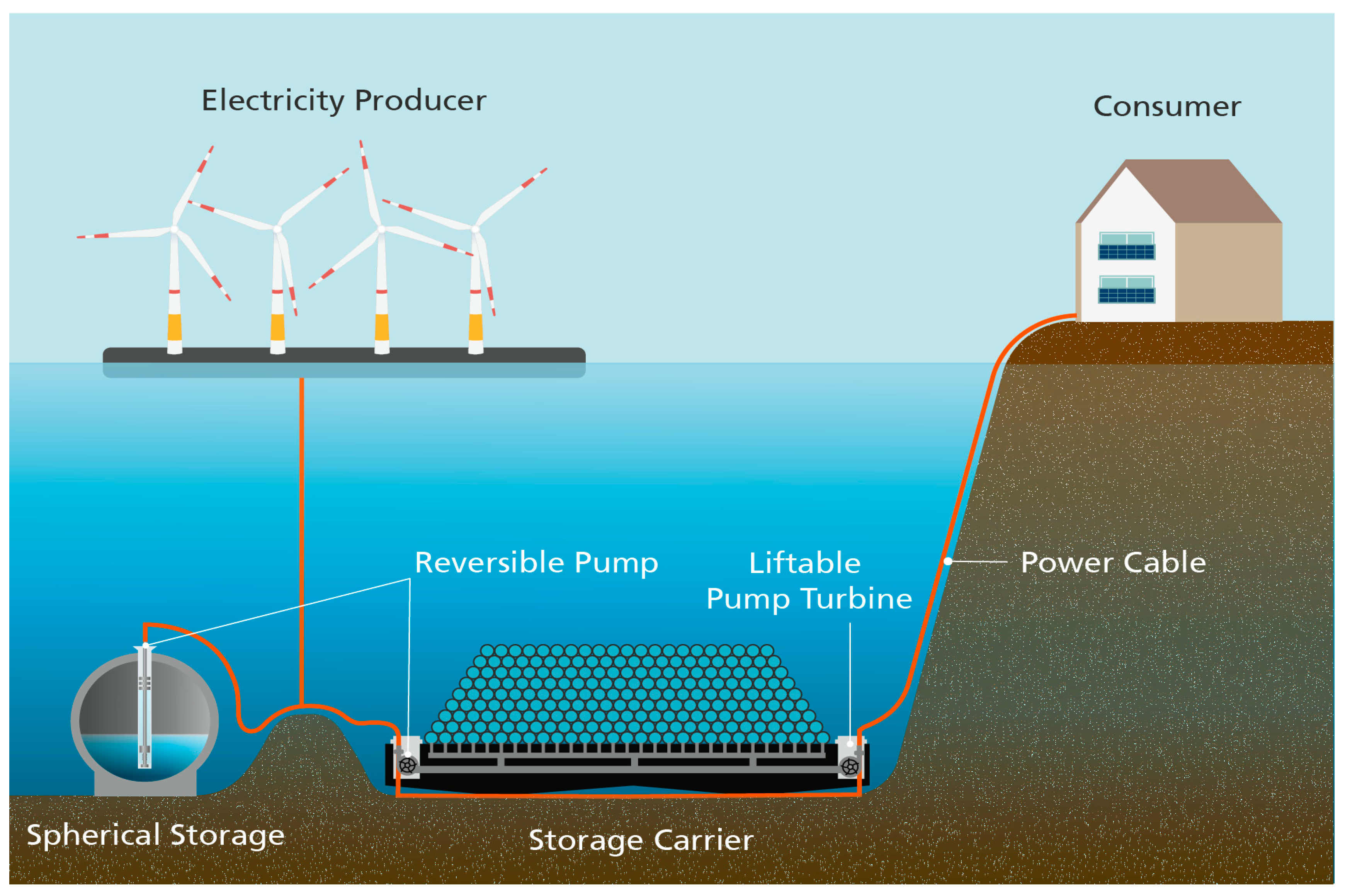
2. Working Scheme of a U.PSH

The water pressure in a lake or in the ocean increases linearly with the depth. Thus, if the water is 400 m deep, the pressure on the seabed is about 40 bar, and at a 4000 m depth, it is about 400 bar. If one places an empty concrete sphere on the floor of the lake, there is a huge pressure difference between the inside and outside of the sphere (Figure 4). Mounting a reversible hydroelectric turbine, a so-called “pump turbine”, at the bottom of the sphere, electricity is generated when the water flows into the sphere. At times of energy surplus, by pumping the water out of the sphere against the high surrounding pressure, electricity can be stored. The pressure inside the sphere corresponds to a water vapor pressure of around 50 mbar. At a water depth of 4000 m, the pressure difference between the inside and the outside is about 400 bar, corresponding to a stored energy of about 10 kWh per cubic meter water.
In analogy to the conventional PSH, the sea itself is used as an upper reservoir, the lower reservoir is formed by a sphere with the volume V0. Only a cable connection between the turbine and the sea surface is required, conducting the electricity generated to the grid and vice versa. The working principle of storing electric energy is thus very simple and straightforward (Figure 5).
The energy balance of the storage process is as follows: the water in the sphere on the bottom of the lake has, de facto, to be lifted up to the surface of the lake by converting electric energy into potential energy of the water in the gravitational field. Vice versa, regaining electric energy, the potential energy is converted into electric energy. The amount of stored energy E is the product of the water pressure p times the volume V0.
E = p • V0
Here, the water was conceived as an incompressible fluid. Inside the evacuated sphere, only some very low residual water pressure remains at the saturation pressure of about 50 mbar. In the general case, one has to assume a compressible fluid with a noticeable pressure dependence of its density. For this reason, the presence of other non-condensing gases such as air in the sphere in addition to water vapor should be avoided. In addition to the feasibility of such a storage system, the economics in relation to production and maintenance costs and ultimately in relation to electricity storage costs play an important role and will be discussed below.

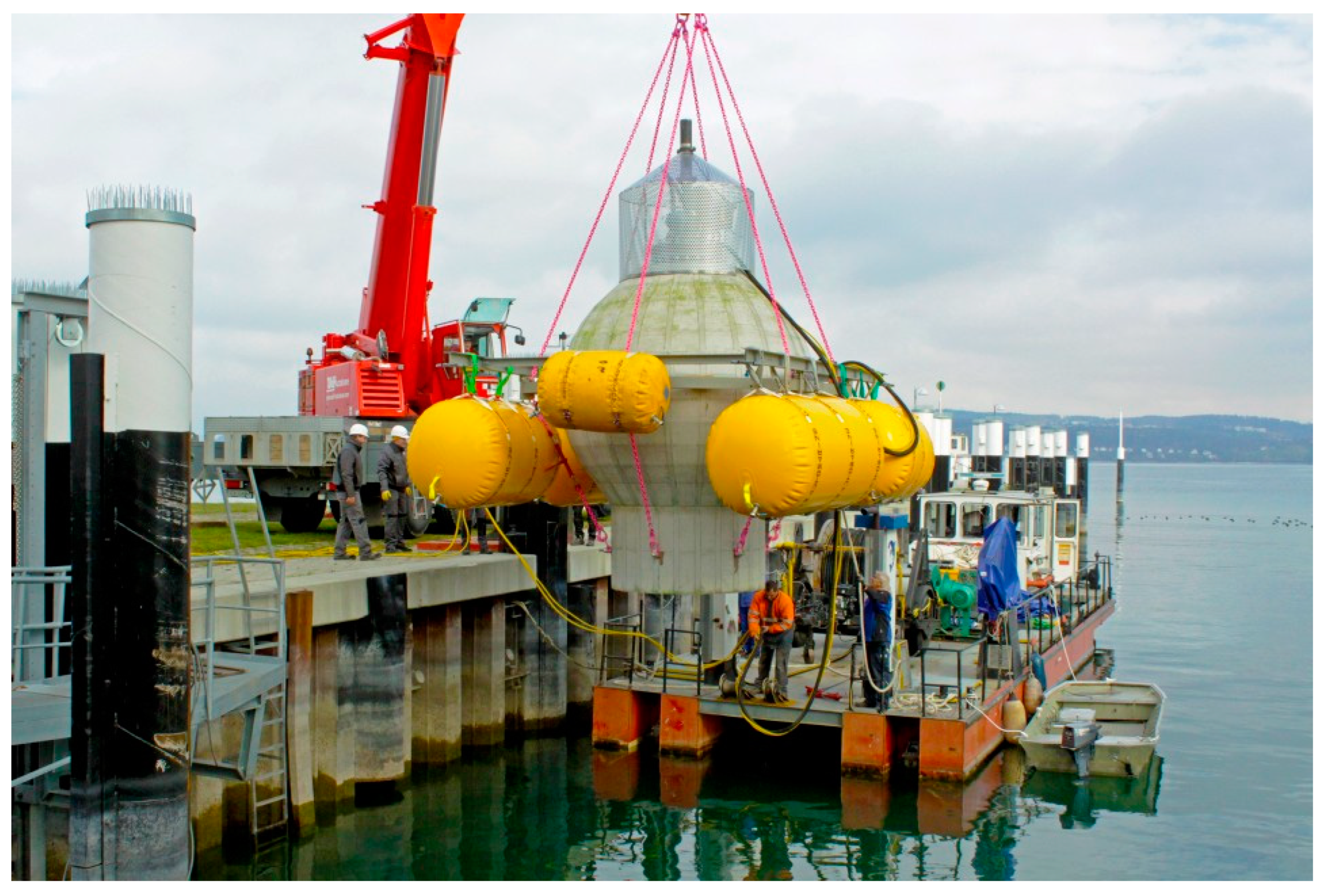
3. Experimental Test of the U.PSH—The StEnSea Project

A few days before the Fukushima event, several patents [42,43,44,45] for such a U.PSH energy storage device were submitted, by A. H. Slocum et al. [42] in the US and by the two authors H. Schmidt-Böcking and G. Luther [43,44,45] to the German Patent Office in Munich. Only a few weeks later (1 April 2011), the U.PSH storage idea on the floor of the ocean was published in the German newspaper “FAZ” by G. Küffner [54,55]. Based on that, a research proposal was submitted to the former German Federal Ministry of Economics (BMWi) by the Fraunhofer Institute for Energy Economics and Energy System Technology—IEE in Kassel and HOCHTIEF Solutions AG in Essen for building and testing a prototype of a U.PSH. The funded project named StEnSea (Storing Energy at Sea) tested a functional model in November 2016 (Figure 6) in Lake Constance [48,49].
The results of the one-month testing phase proved that the StEnSea U.PSH was fully functioning as expected. The “Final Report” [49] of the StEnSea project provided convincing evidence that the U.PSH technology is well understood and could be applied for storing electric energy. Besides further technological aspects (Section 4), one important question was: is this way of energy storage competitive with others?
In the final report [49], a proposed StEnSea system (Figure 7) is presented, and for 120 single spherical segments (a total storage volume of 1.46 million m3 with a 750 m water depth), the storage capacity and the installation costs are estimated. Figure 7 shows the principle set-up of a StEnSea plant built from multiple spheres. At a depth of 750 m, a system of 120 segments could yield an energy storage capacity of about 2.2 GWh. The 120 turbines with 5 MW each would have a total power of 600 MW. The total installation costs were estimated (page 75 [49] outlines an estimate of EUR 940 million, i.e., EUR 430/kWh or EUR 642/m3. The report concluded that such a U.PSH system could store electric energy already at an economically competitive cost.

4. Proposals of Other Schemes of U.PSH

Starting from this, we believe that U.PSH systems can also be constructed using an alternative design that may require lower installation costs and have easier maintenance. However, before discussing other possible schemes of U.PSH, some important aspects of possible physical challenges when using such U.PSH must be considered here. Because of the high pressure difference between in- and outside of the concrete sphere, the shape and the thickness of the walls of the sphere are crucial for stability of the sphere and thus for its lifetime. Because of the buoyancy of the sphere in the water, the total weight of the empty sphere must be higher than the buoyancy. This can be achieved either by the thickness of the wall or by adding a ballast like sand or gravel. Because of possible earthquakes, the total system should be made of many independent segments. Since the turbine on the seabed needs maintenance (about every 15 to 25 years), the turbine (including shut-off valve, etc.) should be movable in one piece to the surface. This requires a new turbine set-up, which will be discussed below. The energy storage capacity and the turbine power should be adequate to match the power system’s needs. The daily charging/discharging time is determined by the requirement that in an approximately 4–10 h pumping time (mean time of storage cycle is about one day), the full storage capacity is reached. Thus, for a segment capacity of 5 GWh with two turbines, the power of each turbine should be about 250 MW.
On the one hand, the construction might be easier when the whole storage system is manufactured as one unit in a dry dock before launching. On the other hand, this might have drawbacks in terms of the modularity compared to a spherical design. Different, potentially less costly alternatives to U.PSH will be discussed in the next section.

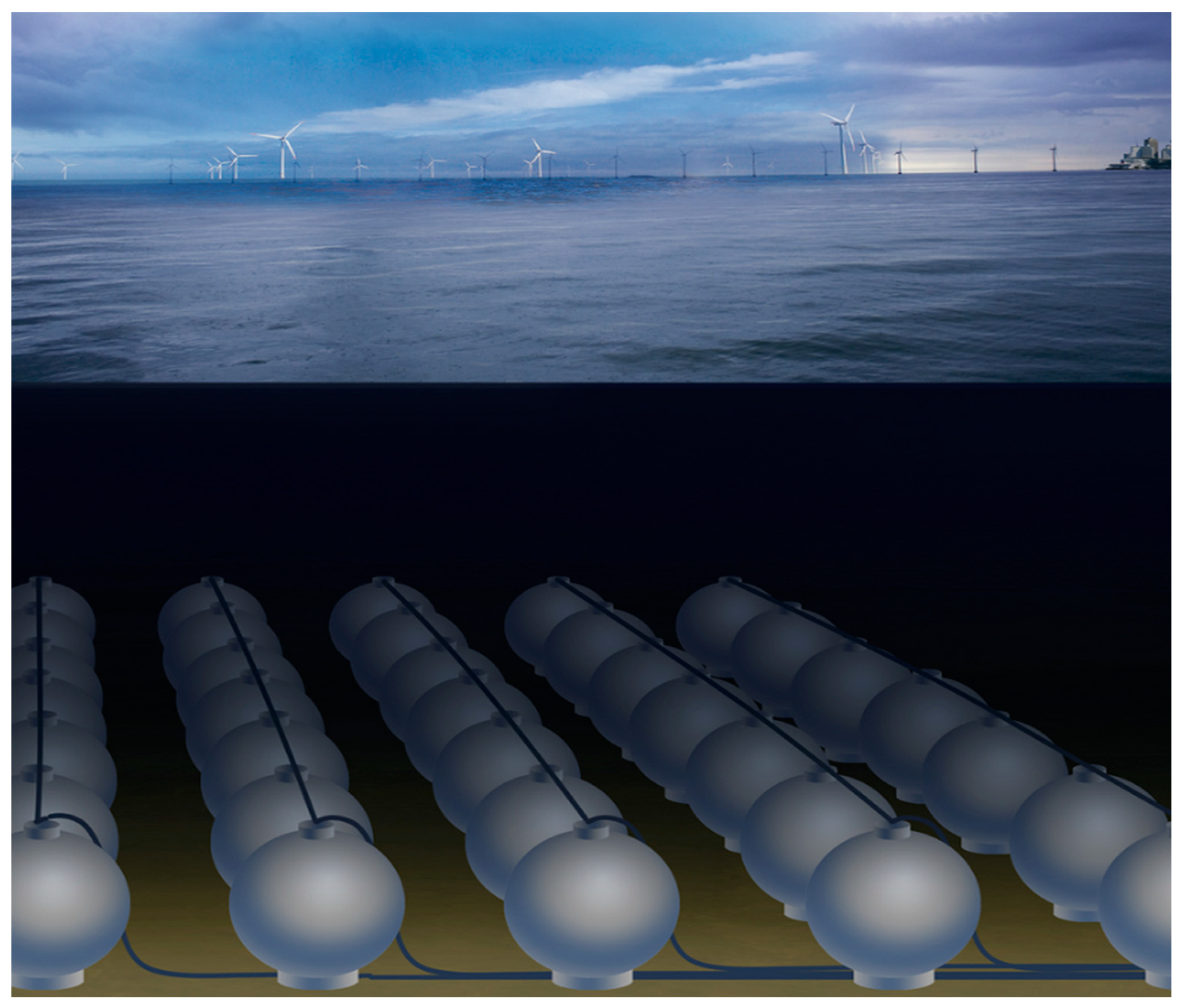
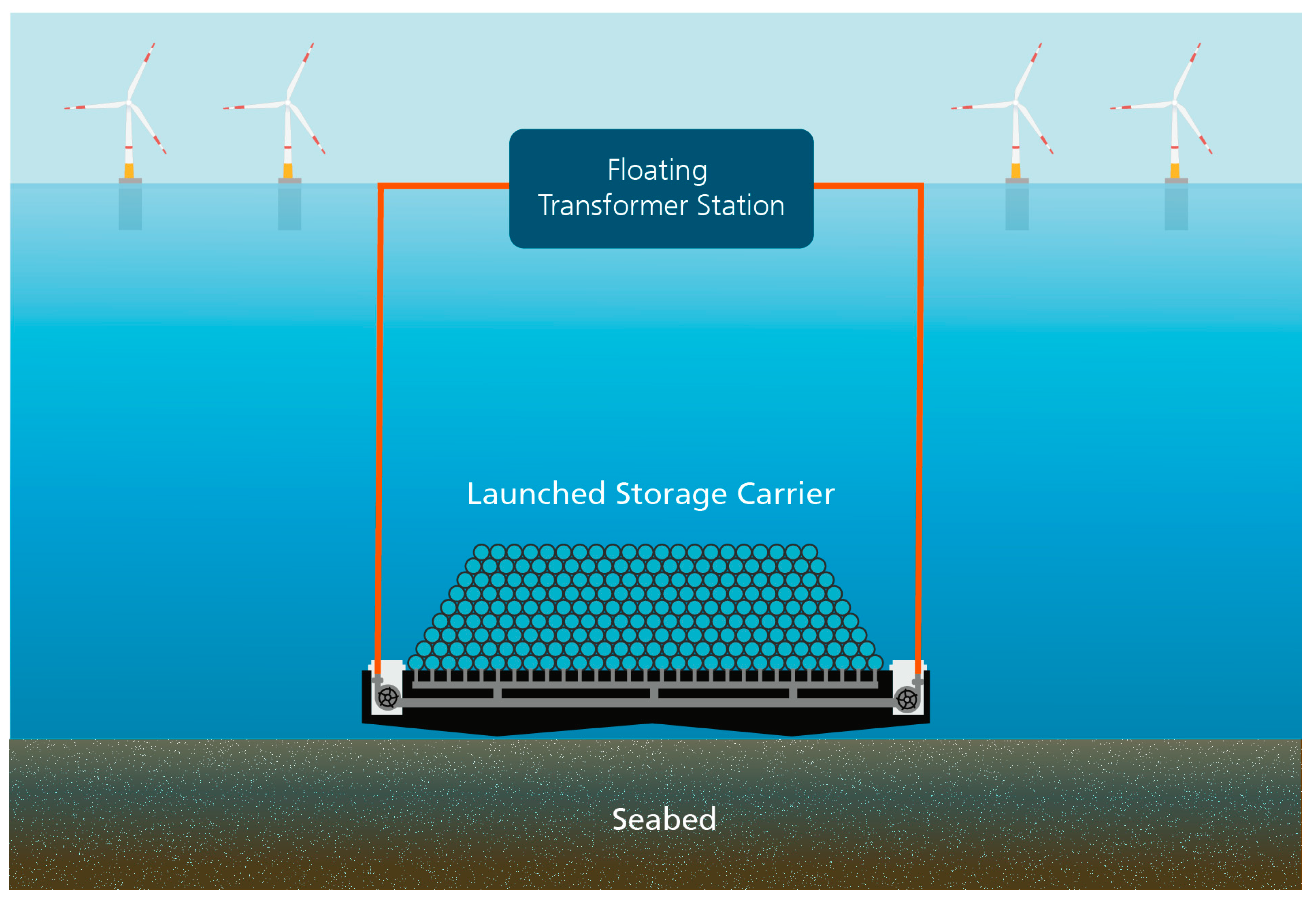
4.1. Storage Carrier U.PSH for Offshore Energy Storage

In deep water, a concrete-made storage carrier might be a preferable economic solution. The storage carrier U.PSH (SC-U.PSH) is manufactured in a dry dock on shore. The sub-construction of the carrier (black part in Figure 8) is made of concrete. It includes a piping system, which connects the two turbines (right and left in Figure 8) at both ends of the carrier with all empty small containers mounted on the sub-construction. The small containers may be pipes or spheres, depending on the structural analysis of the whole SC-U.PSH. The size of the carrier is chosen here so that the final water net storage volume is about 500,000 m3. When the container carrier is installed at a certain depth h (in m), the final electric energy storage capacity E is then
E = h (in m) • 500,000 m3/400 m (kWh/m3).
For h = 750 m, the storage capacity is E = 0.94 GWh, and for h = 4000 m, the storage capacity is E = 5.0 GWh. Since the total volume is 825,000 m3 (325,000 m3 concrete, specific weight about 2.5 kg/L), the empty storage carrier does swim and can therefore be moved from the dry dock to the location where it should be lowered to the seabed. A soft placement on the floor can be achieved by filling the SC-U.PSH with some water. To control a soft precise launch, balloons can be connected to the carrier as well. To prevent the buoyancy of the empty spheres, about 10,000 m3 of water must always remain in the spheres.
In Figure 9, an example of a SC-U.PSH, placed on the ocean floor, is shown, obtaining its renewable energy from floating wind turbines. The electric cables are indicated in red.

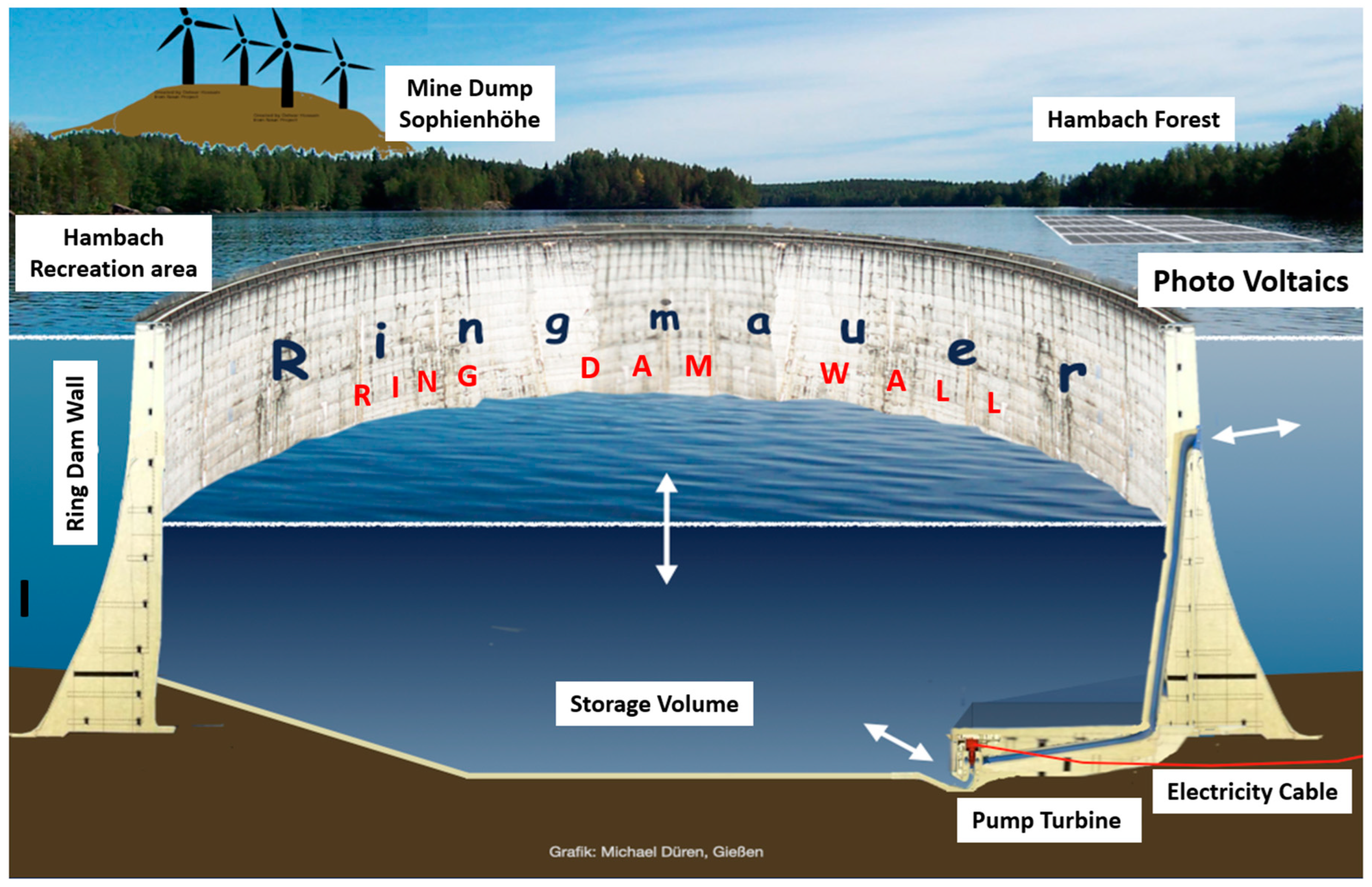
4.2. U.PSH in Flooded Open Cast Coal Mining Pits

To construct an onshore U.PSH, one needs deep lakes, e.g., Lake Constance (maximum depth: 251 m), which is the only natural lake in Germany that is close to the required depth. However, to protect this unique valuable natural heritage, the people and consequently the political administration would never allow the installation of a U.PSH there. Fortunately, open mining pits could be used for U.PSH as well. These places are, e.g., open coal pits that are or will be shut down in the near future. These mining pits will be flooded when not in operation anymore. For example, the lignite mining pit in Hambach (located between Cologne and Aachen, Germany; see Figure 10) is 460 m deep and its deepest floor is about 1 km × 4 km in size. In 2030, the lignite harvesting there will end and the whole area will be converted into a recreation park. Installed at the bottom of the mining pit, the U.PSH would be invisible after flooding the pit. The operating U.PSH would only be noticed by lake level fluctuations (typically some meters in height).
The U.PSH can be installed before flooding the pit or even later when it is flooded. In the latter case, the single storage segments can be manufactured in a dry-dock as a storage carrier (see Section 4.1), floated to the final location and then launched by putting additional ballasts on to overcome the boost.
Since the water pressure in the Hambach mine would be about 40 bar, the net volume of each segment should be about 1 million m3, yielding about 1 GWh energy storage capacity. Assuming a 10 h daily storage time, the required turbine should have a power of about 100 MW.
Which other requirements must be considered?
  • The wall plus possible inner construction parts plus sub-construction plus upper dome should be made from concrete, thick enough to withstand the 40 bar ambient pressure.
  • The buoyancy can be compensated by the weight of the concrete structure itself or by added ballast like sand or gravel.
  • Since concrete is rather cheap and easy to process (climbing or sliding formwork), all bulky parts should be made of concrete where possible.
  • The shape of each segment should render the optimal net storage volume.
  • The turbine plus shut-off valve must be movable in one piece to the surface for maintenance.
  • The installation should be low-priced, safe and fast.
Many shapes and forms of segments might fulfill the above-listed requirements. A few possible forms will be discussed here. Segment A, shown in Figure 11 (left part), is made of hexagonal pipes (e.g., 37 pipes), each with an inner diameter of about 15 to 20 m and about 120 m in height. This hexagonal structure ensures that many of these segments can be placed adjacent to each other on the lake floor to yield a high net total storage volume. Each segment can be manufactured in concrete in sliding form and is not very costly since all inner walls do not have to withstand high pressure. The buoyancy can be compensated by cheap ballast material.
A further geometry variation was developed and statically optimized by T. Bender at the Institute of Innovative Structures of the University of Applied Sciences in Mainz under the supervision of A. Garg. The developed topology has a storage volume of 1,000,000 m3 and is equipped with a central 100 MW turbine. The storage tank is cylinder-shaped with an end dome, so the structure is mainly exposed to compressive stresses from the pressure of the ambient water. Concrete is the ideal building material for this structure. A steel tube is arranged in the center of the storage tank in which the pump turbine, protected from external influences, is installed. Through this pipe and a service opening at the apex of the dome, the entire pump unit can be freed and replaced. Consequently, maintenance of the pump is thus possible above the water surface.
The entire storage unit is secured against floating by a tie-back foundation plate and can be constructed without major digging operations. The water supply line is located under the basement so that the maximum possible inflow pressure is ensured at all times. Based on these specifications, a civil engineering study for the construction of a single storage tank was carried out at the University of Applied Sciences in Mainz for the location of the Hambach open mining pit in Germany. In addition to the pure material and construction costs, this list also includes costs for engineering support and project planning, for approval procedures and for construction site logistics.
If the storage tank is built as depicted in Figure 12, the costs can be reduced by connecting three storage facilities in parallel in a cloverleaf shape with a central pump turbine (the electrical power is consequently 300 MW). This also reduces the maintenance effort and the associated costs while at the same time increasing the risk of failure. Further information can be found in a separate SWAT analysis on the construction and operation of this storage type.
Last but not least, the so-called “Ringmauer” storage system (“Ring dam wall” PSH) might provide one solution for short-term storage (Figure 13) [10,47]. If such an underwater basin becomes broader and higher, then one may reach the point where it just overlooks the surface of the lake and a new quality is reached: the “Ringmauer” or ring dam wall reservoir, an annular closed dam wall giving the lower reservoir of a huge PSH using the surrounding lake as the upper basin [10].
There are several advantages:
  • The technology is based on the well-proven concept of an arch dam, which for many decades and all over the world has been standard for reservoirs with stable rock supports.
  • However, in the case of the ring dam wall, no pushing away of the structure by water pressure is possible as the ring is evenly exposed to the water pressure from all sides so that the displacement forces cancel each other out. Thus, for the ring arch dam, “stable mountain flanks” are no longer necessary.
  • Because the reservoir enclosed by the ring dam wall is open at the top, no lid with supports, pillars and domes is necessary.
  • The inside of the ring dam wall represents the air side of a reservoir. There are no buoyancy problems, which people know from experience with the many reservoirs all over the world.
  • Exploitation of a large range of level difference between the basins. The level in the deep inner reservoir, which is optically hidden from the outside, can be varied in an extraordinarily wide range. This suggests the use of pump turbines connected in series, which can be placed at different heights on the dam wall to avoid excessive inlet pressure. In the course of a storage cycle, at least a large proportion of the pump turbines can be used in different configurations by means of variable parallel and series connections, resulting in good utilization of the pump turbines.
  • Additional storage space at the bottom (Figure 14, area 37). From the business of open pit mining, big machines digging deep holes for moving the soil and extracting lignite are now available, enabling cost-effective storage space at the bottom of the ring dam wall reservoir to be produced.

5. Conclusions

The U.PSH installed on the seabed or lakebed can contribute to the ongoing energy transition [56,57,58,59]. Lots of suitable locations around the globe exist for U.PSH, and the overall costs can compete with other storage options. The installation of such U.PSH technology is, however, more economical if larger GWh-scale storage systems are constructed or larger numbers of smaller units (spheres) are installed. Thus, the initial total investment costs are huge too. Considering the lifetime and maintenance of the U.PSH components (concrete structure and turbines), the technology might provide a valuable future storage option for short-term storage (hours to days). The technology has the potential to ensure that the energy transition remains feasible and might play an important future role for the safety and affordability of electricity for industry and every citizen.
The above presented renewable energy production was mainly based on German energy sources like photovoltaics and on- and off-shore wind power. Considering the energy sources in a larger area of Europe, renewable energy production can be much more efficient, especially when including the Mediterranean area. Not only does the daily sunshine there yield more sun hours but, more important, the so-called “winter lull” (which, in Germany, is several months in duration) is absent. Therefore, a combined strategy involving both central European and Mediterranean countries—like in the project DESERTEC [60,61]—could make use of these important advantages.
The volatility of renewable power generation, as well as the fluctuating consumption of power (day–night cycle), still requires significant capacities of energy storage, which can be located at the place of the power generation, at the place of the power consumption and/or at junctions of big power lines. In addition, significant energy storage is required at the location of the consumer side for three reasons: to handle the fluctuating power demand of the consumer, to buffer the local solar and wind power production, and for energy security in case of problems with long-distance power transport. One storage technology of choice is large pump storage systems, as outlined in this paper.

Author Contributions

Investigation, H.W.S.-B., G.L., M.D., M.P., T.B., A.G., B.E. and H.F.; writing—original draft, H.W.S.-B.; writing—review and editing, G.L., M.D., M.P., T.B., A.G. and B.E. All authors have read and agreed to the published version of the manuscript.

Funding

This research was funded by the German Ministry of Economic Affairs and Energy (BMWi) for financing the StEnSea project (Grant number 0325584B).

Data Availability Statement

Data are contained within the article.

Acknowledgments

We acknowledge the helpful and motivating discussions with and support from many colleagues including (alphabetic sequence): Jochen Bard, Holger Becker, Christian Dick, Franz Wilhelm Iven, Thorsten Luther, Wilhelm Mecklenbrauck, Volker Mergel, Julian Meyer, Jürgen Mlynek, Hauke Müller-Späth, Henry Riße, Joachim Schwister, Alex Slocum, Andrè Stinka, Joachim Ullrich, Kurt Wagemann, Michael Weidenmüller, Leonard Wessel, Markus Wirth, and Karl Friedrich Ziegahn. The authors would also like to thank the German Ministry of Economic Affairs and Energy (BMWi) for financing the StEnSea project (grant number 0325584B) and the StEnSea II project (grant number 03EI4047A).

Conflicts of Interest

All authors declare that the research was conducted in the absence of any commercial or financial relationship that could be construed as a potential conflict of interest. The authors declare no conflict of interest.

References

  1. Sterner, M.; Stadler, I. (Eds.) Handbook of Energy Storage-Demand, Technologies, Integration; Springer GmbH: Berlin, Germany, 2019; 844p, ISBN 978-3-662-55503-3. [Google Scholar]
  2. Brown, T.W.; Bischof-Niemz, T.; Blok, K.; Breyer, C.; Lund, H.; Mathiesen, B.V. Response to ‘Burden of proof: A comprehensive review of the feasibility of 100% renewable-electricity systems’. Renew. Sustain. Energy Rev. 2018, 92, 834–847. [Google Scholar] [CrossRef]
  3. Hansen, K.; Mathiesen, B.V.; Skov, I.R. Full energy system transition towards 100% renewable energy in Germany in 2050. Renew. Sustain. Energy Rev. 2019, 102, 1–13. [Google Scholar] [CrossRef]
  4. Ruhnau, O.; Qvist, S. Storage requirements in a 100% renewable electricity system: Extreme events and inter-annual variability. Environ. Res. Lett. 2022, 17, 044018. [Google Scholar] [CrossRef]
  5. Gyuk, I. DOE Global Energy Storage Database, Sandia National Laboratories. 2021. Available online: https://sandia.gov/ess-ssl/gesdb/public/index.html (accessed on 22 September 2021).
  6. Shan, R.; Reagan, J.; Castellanos, S.; Kurz, S.; Kittner, N. Evaluating emerging long duration energy storage technologies. Renew. Sustain. Energy Rev. 2022, 159, 112240. [Google Scholar] [CrossRef]
  7. Akinyele, D.O.; Rayudu, R.K. Review of energy storage technologies for sustainable power networks. Sustain. Energy Technol. Assess. 2014, 8, 74–91. [Google Scholar] [CrossRef]
  8. Brown, T.; Hampp, J. Ultra-Long-Duration Energy Storage Anywhere: Methanol with Carbon Cycling. Joule 2023, 7, 2414–2420. [Google Scholar] [CrossRef]
  9. Bundesnetzagentur: Data Archive SMARD. 2023. Available online: https://www.smard.de/home/downloadcenter/download-marktdaten/ (accessed on 31 January 2023).
  10. Luther, G.; Schmidt-Böcking, H. The Role of Short-Term Storage Like Hydropower in Abandoned Opencast Mines in the Energy Transition. In 791. WE-Heraeus-Seminar (2023)/The Physical, Chemical and Technological Aspects of the Fundamental Transition in Energy Supply from Fossil to Renewable Sources—Key Aspect: Energy Storage, Lecture 11.1. Available online: http://www.fze.uni-saarland.de/AKE_Archiv/AKE2023_Heraeus.Sp/Vortraege/AKE2023-H.Sp_11.1_Luther_Role.ofShortTermStorage_PSKW.imTagebauloch.pptx (accessed on 15 December 2022).
  11. Ulvestad, A. A Brief Review of Current Lithium Ion Battery Technology and Potential Solid State Battery Technologies. arXiv 2018, arXiv:1803.04317. [Google Scholar]
  12. Redondo-Iglesias, E.; Venet, P.; Pelissier, S. Efficiency Degradation Model of Lithium-Ion Batteries for Electric Vehicles. IEEE Trans. Ind. Appl. 2019, 55, 1932–1940. [Google Scholar] [CrossRef]
  13. Smith, K.; Saxon, A.; Keyser, M.; Lundstrom, B.; Cao, Z.; Roc, A. Life prediction model for grid-connected Li-ion battery energy storage system. In Proceedings of the 2017 American Control Conference (ACC), Seattle, WA, USA, 24–26 May 2017. [Google Scholar]
  14. Amirthan, T.; Perera, M.S.A. The role of storage systems in hydrogen economy: A review. J. Nat. Gas Sci. Eng. 2022, 108, 104843. [Google Scholar] [CrossRef]
  15. King, M.; Jain, A.; Bhakar, R.; Mathur, J.; Wang, J. Overview of current compressed air energy storage projects and analysis of the potential underground storage capacity in India and the UK. Renew. Sustain. Energy Rev. 2021, 139, 110705. [Google Scholar] [CrossRef]
  16. Aghahosseini, A.; Breyer, C. Assessment of geological resource potential for compressed air energy storage in global electricity supply. Energy Convers. Manag. 2018, 169, 161–173. [Google Scholar] [CrossRef]
  17. Swinfen-Styles, L.; Garvey, S.D.; Giddings, D. Combining wind-driven air compression with underwater compressed air energy storage. In Proceedings of the 2019 Offshore Energy and Storage Summit (OSES), Brest, France, 10–12 July 2019. [Google Scholar]
  18. Novotny, V.; Basta, V.; Smola, P.; Spale, J. Review of Carnot Battery Technology Commercial Development. Energies 2022, 15, 647. [Google Scholar] [CrossRef]
  19. Benato, A.; Stoppato, A. Pumped Thermal Electricity Storage: A technology overview. Therm. Sci. Eng. Prog. 2018, 6, 301–315. [Google Scholar] [CrossRef]
  20. Steinmann, W.D.; Jockenhöfer, H.; Bauer, D. Thermodynamic Analysis of High-Temperature Carnot Battery Concepts. Energy Technol. 2020, 8, 1900895. [Google Scholar] [CrossRef]
  21. Giesecke, J.; Heimerl, S.; Mosonyi, E. Wasserkraftanlagen-Planung, Bau und Betrieb; Springer: Berlin, Germany, 2014; 962p, ISBN 978-3-642-53870-4. [Google Scholar]
  22. Strobl, T.; Zunic, F. Wasserbau-Aktuelle Grundlagen—Neue Entwicklungen; Springer: Berlin/Heidelberg, Germany, 2008; 614p, ISBN-13 978-3-540-22300-9. [Google Scholar]
  23. US Department of Energy (DOE), Office of Energy Efficiency & Renewable Energy. Pumped Storage Hydropower. Available online: https://www.energy.gov/eere/water/pumped-storage-hydropower (accessed on 1 December 2022).
  24. International Hydropower Association (iha). Available online: https://www.hydropower.org/factsheets/pumped-storage (accessed on 19 August 2023).
  25. Goldisthal: Homepage of the Operator. Available online: https://powerplants.vattenfall.com/de/goldisthal (accessed on 1 December 2022).
  26. Fyke, A. The Fall and Rise of Gravity Storage Technologies. Joule 2019, 3, 625–630. [Google Scholar] [CrossRef]
  27. Hunt, J.D.; Byers, E.; Wada, Y.; Parkinson, S.; Gernaat, D.E.; Langan, S.; van Vuuren, D.P.; Riahi, K. Global resource potential of seasonal pumped hydropower storage for energy and water storage. Nat. Commun. 2020, 11, 947. [Google Scholar] [CrossRef] [PubMed]
  28. Hunt, J.D.; Zakeri, B.; Lopes, R.; Barbosa, P.S.F.; Nascimento, A.; de Castro, N.J.; Brandão, R.; Schneider, P.S.; Wada, Y. Existing and new arrangements of pumped-hydro storage plants. Renew. Sustain. Energy Rev. 2020, 129, 109914. [Google Scholar] [CrossRef]
  29. Stocks, M.; Stocks, R.; Lu, B.; Cheng, C.; Blakers, A. Global Atlas of closed-loop pumped hydro energy storage. Joule 2021, 5, 270–284. [Google Scholar] [CrossRef]
  30. Wang, Z.; Carriveau, R.; Ting DS, K.; Xiong, W.; Wang, Z. A review of marine renewable energy storage. Int. J. Energy Res. 2019, 43, 6108–6150. [Google Scholar] [CrossRef]
  31. Rehman, S.; Al-Hadhrami, L.M.; Alam, M.M. Pumped hydro energy storage system: A technological review. Renew. Sustain. Energy Rev. 2015, 44, 586–598. [Google Scholar] [CrossRef]
  32. Popp, M. Künstliche Landschaft für Pumpspeicherkraftwerk. In Speicherbedarf bei einer Stromversorgung mit Erneuerbaren Energien; Springer: Berlin/Heidelberg, Germany, 2010; ISBN 978-3-642-01926-5. [Google Scholar]
  33. Wolfgang Kempten, Unter dem Ruhrgebiet Entsteht ein Riesiger Energiespeicher in der Erde, VDI Nachrichten. 29 August 2016. Available online: https://www.ingenieur.de/technik/fachbereiche/energie/unter-ruhrgebiet-entsteht-riesiger-energiespeicher-in-erde/ (accessed on 17 August 2023).
  34. Madlener, R.; Specht, J.M. An exploratory economic analysis of underground pumped-storage hydro power plants in abandoned deep coal mines. Energies 2020, 13, 5634. [Google Scholar] [CrossRef]
  35. Pujades, E.; Orban, P.; Bodeux, S.; Archambeau, P.; Erpicum, S.; Dassargues, A. Underground pumped storage hydropower plants using open pit mines: How do groundwater exchanges influence the efficiency? Appl. Energy 2017, 190, 135–146. [Google Scholar] [CrossRef]
  36. Menendez, J.; Fernandez-Oro, J.M.; Galdo, M.; Loredo, J. Efficiency analysis of underground pumped storage hydropower plants. J. Energy Storage 2020, 28, 101234. [Google Scholar] [CrossRef]
  37. Tan, Y.; Zhou, X.; Xu, Y.; Chen, H.; Qin, W. Seawater pumped hydro energy storage: Review and perspectives. Energy Storage Sci. Technol. 2017, 6, 35–42. [Google Scholar]
  38. Slocum, A.H.; Dündar, G.; Hodder, B.G.; Meredith, J.D.C.; Homsi, E.H.; Garg, A.; Lay, C.; Schmidt-Böcking, H.; Luther, G. Large Scale Manufacture and Development of Offshore Renewable Energy Harvesting and Storage System. In Proceedings of the 12th euspen International Conference, Stockholm, Sweden, 4–8 June 2012. [Google Scholar]
  39. Schmidt-Böcking, H.; Luther, G.; Lay, C.; Bard, J. Das Meer-Ei. Phys. Unserer Zeit 2013, 44, 194. [Google Scholar] [CrossRef]
  40. Slocum, A.H.; Fennell, G.E.; Dundar, G.; Hodder, B.G.; Meredith, J.D.; Sager, M.A. Ocean Renewable Energy Storage (ORES) System: Analysis of an Undersea Energy Storage Concept. Proc. IEEE 2013, 101, 906–924. [Google Scholar] [CrossRef]
  41. Slocum, A.H. Symbiotic offshore energy harvesting and storage systems. Sustain. Energy Technol. Assess. 2015, 11, 135–141. [Google Scholar] [CrossRef]
  42. Slocum, A.H.; Fennell, G.E.; Greenlee, A.S. Offshore Energy Harvesting, Storage, and Power Generation System. Patent: WO 2011/112561 A2. Available online: https://patents.google.com/patent/US8698338B2/en (accessed on 8 September 2011).
  43. Schmidt-Böcking, H.; Luther, G. “Pumpspeicherkraftwerk”; DE 10 2011 013329.1. Available online: https://depatisnet.dpma.de/DepatisNet/depatisnet?action=pdf&docid=DE102011013329A1&xxxfull=1 (accessed on 13 September 2012).
  44. Schmidt-Böcking, H.; Luther, G. “Pumpspeicherkraftwerk”; DE 10.2011 118206.7. Available online: https://depatisnet.dpma.de/DepatisNet/depatisnet?action=pdf&docid=DE102011118206A1&xxxfull=1 (accessed on 16 May 2013).
  45. Luther, G.; Schmidt-Böcking, H. Schacht-Pumpspeicherkraftwerk DE 10 2011 105307.0. Available online: https://depatisnet.dpma.de/DepatisNet/depatisnet?action=pdf&docid=DE102011105307A1&xxxfull=1 (accessed on 20 December 2012).
  46. Schmidt-Böcking, H.; Luther, G. PCT/EP2021/061424: Modulares Unterwasser-Pumpspeicherkraftwerk-Reservoir. Available online: https://patents.google.com/patent/WO2021219854A1/de?oq=PCT%2fEP2021%2f061424:+Modulares+Unterwasser-Pumpspeicherkraftwerk-Reservoir.+ (accessed on 4 November 2021).
  47. Luther, G.; Schmidt-Böcking, H. DE 10 2020 004 099: H.: “Pumped Storage Power Plant with a Reservoir Enclosed by a Ring Dam Wall”. Available online: https://depatisnet.dpma.de/DepatisNet/depatisnet?action=pdf&docid=DE102021004099A1&xxxfull=1 (accessed on 11 November 2021).
  48. Puchta, M.; Bard, J.; Dick, C.; Hau, D.; Krautkremer, B.; Thalemann, F.; Hahn, H. Development and testing of a novel offshore pumped storage concept for storing energy at sea—Stensea. J. Energy Storage 2017, 14, 271–275. [Google Scholar] [CrossRef]
  49. Puchta, M.; Bard, J.; Dick, C.; Hau, D.; Ackermann, P.; Krautkremer, B.; Hahn, H.; Shan, W.; Thalemann, F.; Panahandeh, B. Final Report (Abschlussbericht): Entwicklung und Erprobung Eines Neuartigen Pumpspeicherkonzeptes zur Speicherung großer Mengen Elektrischer Energie Offshore. Fraunhofer IEE, Internal Project Number: 102830, FKZ 0325584B. Available online: https://www.tib.eu/de/suchen/id/TIBKAT:1015141013/STENSEA-Storing-Energy-at-Sea-Abschlussbericht (accessed on 30 June 2017).
  50. German Patent DE 2931176A1. Available online: https://patents.google.com/patent/DE2931176A1/en (accessed on 12 March 1981).
  51. Morishige, H. (Mitsubishi Heavy Industries), Japanese Patent 2755778B2. Available online: https://patents.google.com/patent/JP2755778B2/en (accessed on 9 January 1992).
  52. DE 2843675: Grüb (1978), Vorrichtung zur Stromerzeugung Mittels Hydrostatischem Druckes in Einem Gewässer. Available online: https://patents.google.com/patent/DE2843675B2/en (accessed on 10 October 1980).
  53. JP 0000 03188395A 16.8.91 Seawater Pumped Storage Power Plant System Combined with Nuclear Power. Available online: https://patents.google.com/patent/JPH03188395A/ja (accessed on 16 August 1991).
  54. Küfner, G. Hohlkugeln Speichern Überschüssigen Windstrom, Faz.net/aktuell/technik-motor/technik. Available online: https://www.faz.net/aktuell/technik-motor/technik/in-der-tiefe-der-meere-hohlkugeln-speichern-ueberschuessigen-windstrom-1608012.html (accessed on 1 April 2011).
  55. Küffner, G. Die Wasserbatterie im Hambacher Loch, Faz.net/aktuell/technik-motor/technik. Available online: https://www.faz.net/aktuell/technik-motor/technik/stromspeicher-fuer-wind-und-solarstrom-bau-einer-wasserbatterie-16328424.html (accessed on 18 August 2019).
  56. Hahn, H.; Hau, D.; Dick, C.; Puchta, M. Techno-economic assessment of a subsea energy storage technology for power balancing services. Energy 2017, 133, 121–127. [Google Scholar] [CrossRef]
  57. Cardno, C.A. Pressure-Powered Generators Could Complement Wind Farms. Civ. Eng. Mag. Arch. 2018, 87. [Google Scholar] [CrossRef]
  58. Dündar, G. Design and Manufacture Study of Ocean Renewable Energy Storage (ORES) Prototype. Master’s Thesis, Massachusetts Institute of Technology, Cambridge, UK, 2012. [Google Scholar]
  59. Fennell, G.E. System Design and Manufacturability of Concrete Spheres for Undersea Pumped Hydro Energy or Hydrocarbon Storage. Master’s Thesis, Massachusetts Institute of Technology, Cambridge, UK, 2011. [Google Scholar]
  60. Desertec. Available online: https://www.wikiwand.com/en/Desertec (accessed on 15 March 2022).
  61. Düren, M. Understanding the Bigger Energy Picture: DESERTEC and Beyond (Springer Briefs in Energy); Springer: Berlin, Germany, 2017; Available online: https://www.springerprofessional.de/understanding-the-bigger-energy-picture/12276266 (accessed on 15 March 2022).
Figure 1. Electric energy production of the week from 12 to 18 April 2021 by wind power and photovoltaics in Germany scaled with factor 4.5 [9] (see text).
Energies 17 00073 g001
Figure 2. (Upper part): Integral values of surplus and uncovered demand, extrapolated for the assumed year 2040 (100% renewables without storage). The brown area shows the daily surplus resulting mainly from photovoltaics, and the blue area shows the uncovered demand in the nighttime. The red areas show the daily loss of electric power due to missing storage capacity. (Lower Part): Integral values of surplus and uncovered demand extrapolated for the assumed year 2040 (100% renewables with 0.5 TWh storage and 10 GW electrolysis). The yellow areas indicate the filling status of the storage before sunrise; the red areas indicate the loss energy.
Energies 17 00073 g002
Figure 3. Typical yearly overall electricity flux scheme in Germany when the energy transition is completed and no imports are needed, ensuring autarky [10].
Energies 17 00073 g003
Figure 4. Schematic display of the “sphere” U.PSH energy storage system. Notice: the reversible hydroelectric turbine should be mounted at the deepest point of the sphere.
Energies 17 00073 g004
Figure 5. Scheme of the U.PSH energy storage system.
Energies 17 00073 g005
Figure 6. Launching of the prototype on 8 November, 2016, in Lake Constance (© Fraunhofer IEE).
Energies 17 00073 g006
Figure 7. Proposed StEnSea system (© Fraunhofer IEE).
Energies 17 00073 g007
Figure 8. SC-U.PSH (e.g., length ≈ 350 m, width ≈ 60 m, height ≈ 40 m) [44,46].
Energies 17 00073 g008
Figure 9. Floating wind turbines with energy storage U.PSH on the ocean floor.
Energies 17 00073 g009
Figure 10. Upper part: View of the present lignite mine of Hambach/Germany (Photo H. Schmidt-Böcking), Lower part: Future vision of U.PSH in the flooded lake as recreation park for sailing.
Energies 17 00073 g010aEnergies 17 00073 g010b
Figure 11. Sketch of segment A. Left: the view from outside, middle: sectional view. The outer pipes have thicker walls to resist the high water pressure; the inner pipes form one storage volume and thus always have the same low pressure. At the bottom of one pipe (here, the one on the right), the turbine is mounted. This pipe provides the water in- and outlet. The wall of this pipe is thicker and prepared to resist the high inner water pressure. Right: Top view of segment A.
Energies 17 00073 g011
Figure 12. Upper part: Cross section of a bell-shaped storage tank, Lower part: Cloverleaf storage system.
Energies 17 00073 g012
Figure 13. Ring dam wall (“Ringmauer-Staubecken”): the lower basin (“storage volume”) of a huge PSH using the surrounding lake as the upper basin [10,47].
Energies 17 00073 g013
Figure 14. Lower storage basin 333, consisting of ring dam wall 3 and bottom storage hole 37, of a PSH operating in residual lake 0 of a former open cast mine. Storage hole 37 will be dredged out of the later lakebed 1 with the existing open cast mining machines (for more detail, see [10,47]).
Energies 17 00073 g014
Disclaimer/Publisher’s Note: The statements, opinions and data contained in all publications are solely those of the individual author(s) and contributor(s) and not of MDPI and/or the editor(s). MDPI and/or the editor(s) disclaim responsibility for any injury to people or property resulting from any ideas, methods, instructions or products referred to in the content.

