Article

Line-Start Permanent Magnet Synchronous Motor Supplied with Voltage Containing Negative-Sequence Subharmonics

1
Department of Ship Electrical Power Engineering, Gdynia Maritime University, 83 Morska St., 81-225 Gdynia, Poland
2
Department of Ship Automation, Gdynia Maritime University, 83 Morska St., 81-225 Gdynia, Poland
*
Author to whom correspondence should be addressed.
Energies 2024, 17(1), 91; https://doi.org/10.3390/en17010091
Submission received: 14 November 2023 / Revised: 18 December 2023 / Accepted: 21 December 2023 / Published: 22 December 2023

Abstract

:
In some power systems, the voltage waveform contains frequency components less than fundamental, called subharmonics or subsynchronous interharmonics. Voltage subharmonics can be both positive- and negative-sequence, independent of their frequency (order). Subharmonics exert harmful effects on sundry electrical equipment, especially on rotating machinery; they cause various noxious phenomena, such as a local saturation of the magnetic circuit, increases in power losses and windings temperature, and torque pulsations leading to vibration of unacceptable severity. Notably, previous works reported excessive vibration of rotating machinery only under no-load, while under full load, rather moderate vibration occurred. This study deals with vibration analysis of a line-start permanent magnet synchronous motor (LSPMSM) supplied with the voltage containing negative-sentence subharmonics. Experimental investigations were conducted for a 3 kW, four-pole production LSPMSM for subharmonics of various values and frequencies. Voltage subharmonics of values significantly less than reported in real power systems were found to cause unacceptable vibration, especially under full load.

1. Introduction

A prevalent power quality disturbance is from voltage waveform distortions. In practice, the voltage waveform is not a perfect sine but contains various additional frequency components. The undesirable components are usually harmonics, but in some systems [1,2,3], subharmonics (subsynchronous interharmonics) and interharmonics (SaIs) also occur—that is, components of a frequency less than fundamental or those that are not integer multiples of the fundamental frequency. Of note, subharmonics are often understood as a kind of interharmonics, but in some works (e.g., [4,5,6]), they are considered separately because of their especially negative effect on electrical equipment [7].
The presence of SaIs in a power system usually originates from the work of various power electronic appliances, renewable sources of energy, and loads of a fluctuating nature, including double-frequency conversion systems (inverters and high-voltage DC links), wind power stations, photovoltaic plants, arc furnaces, laser printers, AC motors driving piston compressors and other time-varying loads [2,8,9,10,11,12,13,14,15,16,17,18,19,20,21,22]. SaIs can also occur in an inverter output voltage because of voltage fluctuations in the DC link [6,13,23]. In fact, cyclic voltage fluctuations [7,24,25,26] are a superposition of the fundamental voltage component and SaIs [7,27,28].
Various works have reported voltage subharmonics of values up to about 1% in real power systems. For example, in [1], significant SaIs were observed in a building located near steelworks, containing numerous non-linear receivers. The maximal value of the squared subharmonics subgroups of frequencies 5, 10, …, and 45 Hz was 0.99% for the 10-minute aggregation time. Authors in [3] analysed a subharmonic resonance of a wind farm. During the resonance, a voltage subharmonic of 8.1 Hz with a value of 1–2% occurred (based on correspondence with the authors of [3]). Furthermore, [2] reported a subharmonic value of 0.9% and frequency of 45 Hz, accompanied by interharmonics values of 1.17%, 0.89%, and 0.931% and frequencies of 135, 225, and 405 Hz, respectively. SaIs contamination was found in a system supplied with diesel generators, caused by high-power top-drive and mud-pump variable frequency drives.
As is well known, the sequence of voltage harmonics is linked to their order (in practice, frequency). Contrastingly, voltage SaIs can be both positive- and negative-sequence, independent of their frequency [21]. In practice, the sequence of SaIs is interconnected with their origination [21].
Subharmonics and, interconnected with them, voltage fluctuations cause various noxious phenomena in transformers, light sources, control systems, and power electronic and measurement equipment [4,7,16,24,27,29,30]. Especially sensitive to subharmonics is rotating machinery (based on [5,14,23,27,31,32,33,34,35,36,37,38,39]). Subharmonics have been reported to cause excessive transverse and torsional vibrations, increases in power losses and windings temperatures, local saturations of magnetic circuits, and speed fluctuations. Particularly high levels of vibration, even leading to drivetrain destruction [12,18], occur under a resonance condition [5,12,18,24,27,33,34]. The most exposed to harmful torsional vibration are drivetrains containing large synchronous generators and motors (based on [10,14]). As a result, allowable levels of voltage SaIs can significantly differ for various installations (e.g., low- vs. medium-voltage generation installations).
Power quality standards generally do not include permissible levels of voltage SaIs. For instance, Standard EN 50160: Voltage characteristics of electricity supplied by public distribution systems [38] states, “The level of interharmonics is increasing due to development of the application of frequency converters and similar control equipment. Levels are under consideration, pending more experience”. Of note, the comment concerns both interharmonics and subharmonics, understood as subsynchronous interharmonics. IEEE-519:2022 Standard for harmonic control in electric power systems [39] discusses the necessity of SaIs limitation, presenting two alternative proposals of limiting curves for non-generation installations. One curve generally limits subharmonics to 0.5%, and the other limits them to 0.3%.
Rotating machinery supplied with voltage containing SaIs is the subject of numerous research works. They usually concern either multi-megawatt powertrains [10,14] or induction motors [5,23,28,31,32,33,34,35]. Furthermore, the effect of SaIs on the line-start permanent magnet synchronous motor (LSPMSM) [40,41] was only preliminarily analysed in the authors’ works [36,37]. Of note, the investigations [36,37] were restricted to currents and vibration under positive-sequence subharmonics. However, determining the permissible levels of voltage SaIs requires comprehensive investigations of their effect on various elements of a power system, including the increasingly popular LSPMSM—a possible successor to the induction motor.
In addition, previous research [5,35,36,37,38] indicated high transverse vibration of the rotating machinery for no-load, while in other load conditions, the observed vibration was generally moderate. At the same time, at least temporarily, many motors carry a load much less than rated [42,43], but this is not typical. In practice, most motors usually work with significantly greater loads [43].
In light of the above considerations, the objectives of this study are formulated as follows: (1) to demonstrate that voltage subharmonics can cause high vibration of rotating machinery for both no-load and full load, and (2) to examine the vibration of the LSPMSM under negative-sequence voltage subharmonics. The results of this research can be useful for power quality standard modification.

2. Origin of Voltage Subharmonics and Interharmonics

The presence of voltage SaIs in the power system usually originates from the work of power electronic equipment, renewable energy sources, and time-varying loads.
The most important SaIs source is considered to be a double-frequency conversion system (DCS) [13], which is a power electronic appliance connecting two AC systems of various frequencies [16]. The DCS comprises a rectifier and an inverter interconnected by a DC link [13,16,21]—in practice, a capacitor or an inductor. During the DCS operation, voltage or current ripples occur in the DC link, which may result in SaIs presence in both input and output sides of the DCS [13,16,21,23]. The frequencies of subharmonics (fsh) and interharmonics (fih) occurring in the input side of the DSC are (based on [16,21])
f s h / i h = f 1 f r ,
f s h / i h = f h f r ,
where f1 is the fundamental frequency, fr is the frequency of ripples occurring in the DC link, and fh is the harmonic frequency characteristic for the given kind of converter, for example, 250 Hz or 350 Hz (in a 50-Hz system). In practice, the DCS containing a p1-pulse rectifier and a p2-pulse inverter produces SaIs of frequencies equal to [16,21]
f s h / i h = ( p 1 m 1 ) f 1 p 2 n f o
where fo is the output frequency of the DCS, m = 0, 1, 2, …, n = 1, 2, 3, …
The above dependency (3) can be likewise applied to cycloconverters [16]. Of note, the PWM inverter produces additional interharmonics, whose frequency depends on the modulation frequency, strategy, and depth [15,16].
SaIs generated by DCSs can be of both positive and negative sequences. In other words, if the frequency described by (1) is greater than zero, the resulting subharmonic or interharmonic component is of positive sequence. Similarly, if the frequency calculated with (2) is positive, the SaI sequence is the same as the same sequence of the harmonic frequency fh [21]. On the contrary, if the frequency determined with (1) or (2) is negative, the SaI sequence is the opposite of the sequence of the fundamental or harmonic component of frequency fh [21], respectively.
Furthermore, ripples occurring in the DC link can be considerably amplified by resonance phenomena, resulting in high SaI contamination. For example, ripple amplification was reported [13] for inverter output voltage fluctuations corresponding to the natural torsional frequency of a power train. This phenomenon can be especially significant for the low inertia moment of a driven appliance [13].
Another reason for SaI occurrence is the work of renewable energy sources, such as photovoltaic plants [18,22] and wind power stations [3,7,12,20]. In the case of wind turbines, the presence of voltage fluctuations and subharmonics originates from such sources as tower resonance, blades passing in the front of the tower, small differences in the blades, wind turbulences, and rotor electrical or mechanical asymmetry [7,12]. Another SaI source is the DCS used in some wind turbines. In addition, in plants equipped with double-fed induction generators, the harmonics of the rotor circuit converter can be transmitted to the stator as SaIs [12].
Especially high SaI contamination [3] may occur during the sub-synchronous interaction of a power plant [3,20]. Of note, the interaction is not characteristic only for wind turbines but may also appear in thermal power stations [20]. The interaction may be categorised as subharmonic resonance and device-dependent sub-synchronous oscillations [20]. It can be either a purely electrical phenomenon or an event involving the torsional resonance of the generator rotating mass [20]. The sub-synchronous interaction can be initiated by a resonance of an LC circuit consisting of various system elements, including compensation capacitors, transformers, and generators, especially after the failure of a transmission line [20]. Additionally, subharmonic resonance can be triggered by the interaction of the current loop controller of the converter of a double-fed induction generator or the interaction between a generator and various power electronic appliances, such as high-voltage DC links, voltage source converters, and power system stabilisers [20].
A prominent source of SaIs includes time-varying loads, which can be divided into regularly fluctuating loads, e.g., welder machines, laser printers, and devices with integral cycle control, and irregularly fluctuating loads, such as arc furnaces [16]. The work of time-varying loads causes current modulation [7,16], resulting in voltage fluctuations [7,25,26,35]. At the same time, sinusoidal voltage fluctuations can be analysed as a superposition of the fundamental voltage component, a subharmonic component, and an interharmonic component of the following frequencies [7,27,31,35]:
f s h = f 1 f m
f i h = f 1 + f m
where fsh is the frequency of the subharmonic component, fih is the frequency of the interharmonic component, and fm is the frequency of voltage fluctuations.
If the frequency described with (4) or (5) is greater than zero, the corresponding subharmonic/interharmonic component is of positive sequence; otherwise, it is of negative sequence (based on [21]). Additionally, periodic voltage fluctuations of any shape can be considered as the simultaneous occurrence of sinusoidal modulations of various frequencies [31].
A specific fluctuating load is the arc furnace, whose feature is the variation of the generated SaIs because of the chaotic arc behaviour [16]. Of note, for the AC arc furnace, the most significant SaIs occur around the fundamental frequency [16,19], while for the DC arc furnace, they occur near the harmonics produced by the rectifier [16]. The arc furnace generates both positive and negative sequence SaIs (based on [16,19,21]).
Other specific fluctuating loads include synchronous and asynchronous motors driving appliances of the pulsating anti-torque, e.g., the piston compressor [8]. The motors may inject especially significant SaI currents when the frequency of the torque pulsations corresponds to the natural torsional frequency of the rigid-body mode [8]. As an example, a 12 MW synchronous motor under an anti-torque pulsation of 50% of the rated value produced an SaI current of frequencies fsh = 43 Hz, fsh = 57 Hz, and values of about 10% of the rated current [8].
Also noteworthy are some receivers and components of the power system that cannot produce SaIs for themselves but generate them when the supply voltage contains a subharmonic or an interharmonic (based on [5,28]). For instance, the induction motor supplied with voltage containing a positive-sequence interharmonic injects a subharmonic of a frequency equal to 2f1fih into the power system [5,28]. Furthermore, the induction motor under a positive-sequence subharmonic generates an interharmonic of a frequency equal to f1 + fsh [5,28]. In one study, a 3 kW induction motor supplied with the voltage containing the subharmonic value of 1% and frequency fsh = 26 Hz injected a current interharmonic of frequency fsh = 76 Hz and value of 23% of the rated current into the power system [5]. This phenomenon is especially significant in the conditions of rigid-body torsional resonance caused by SaI presence in the supply voltage [5].
In summary, both positive- and negative-sequence SaIs can be generated by various commonly used electrical appliances.

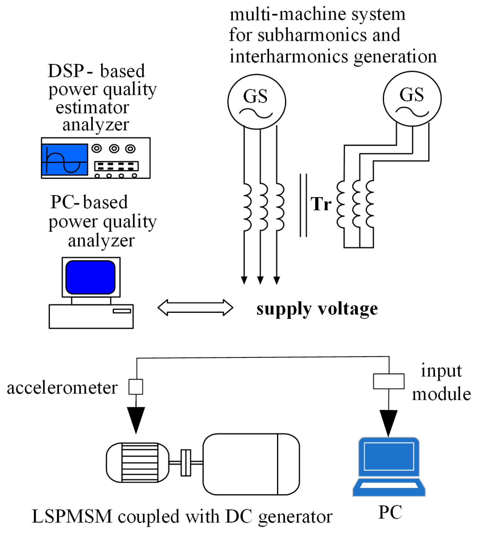
3. Measurement Setup

The experimental equipment comprised the LSPMSM, a multi-machine system for SaIs generation, power quality analysers and a Bruel&Kjear (B&K) system for vibration measurement. The system included a computer with the installed B&K Connect software (version 26.1.0.251), a standalone four-channel data acquisition module B&K type 3676-B-040, an accelerometer calibrator B&K type 4294, and a three-axis accelerometer B&K type 4529-B (frequency range of 0.3–12,800 Hz, a sensitivity of 10 mV/ms−2, maximum shock level peak of 5100 g, and weight of 14.5 g). Before each measurement session, the accelerometer was calibrated, and the measurements were taken and analysed with the chief provisions of the standard ISO 20816-1 Mechanical vibration—Measurement and evaluation of machine vibration—Part 1: General guidelines [44]. The accelerometer indications were recorded and recalculated into the broad-band vibration velocity [44] using the B&K Connect software (version 26.1.0.251).
The LSPMSM tested was type WQuattro L100L-04 with 3 kW rated power. It was loaded with a DC machine (working as a generator), supplying a resistor bank. Table 1 lists the nameplate parameters of the LSPMSM, and Figure 1 shows a photograph with the mounted accelerometer. Because of some modifications, the results of vibration measurements presented in this study cannot be directly compared with previous research [36,37].
The multi-machine system for subharmonic generation (based on [45]) comprised two synchronous generators coupled via a transformer with an experimentally selected number of turns. One generator (type Leroy Somer LSA 42.2M6 6/4,rated power Srat = 23 kVA, rated current Irat = 33 A, direct-axis synchronous reactance xd = 190%, quadrature-axis synchronous reactance xq = 100%) was driven with a rotational speed corresponding to the fundamental frequency, and the other (type GTNSa132s2/08, Srat = 6.5 kVA, Irat = 9.9 A) was driven at the subharmonic frequency [5]. Voltage and current subharmonics were measured with a computer-based power quality analyser (with software elaborated by the authors, employing fast Fourier transform) and an estimator–analyser of power quality [46] developed at Gdynia Maritime University for commercial purposes and certified by the Polish Register of Shipping.
Figure 2 and Figure 3 present a simplified diagram of measurement setup [36] and the flowchart of the vibration measurement (based on [35]), respectively.

4. Results

4.1. Assessment of Vibration Severity

Recommendations concerning the assessment of vibration severity are provided in the standard ISO 20816-1 Mechanical vibration—Measurement and evaluation of machine vibration—Part 1: General guidelines [44]. The standard [44] specifies four evaluation zones: Zone A, Zone B, Zone C, and Zone D. Vibrations corresponding to Zone A are generally characteristic of newly commissioned machines. Vibrations falling into Zone B are acceptable for long-term unrestricted operation, while those within Zone C can be accepted for a limited period, for example, until machine repair or replacement. Finally, vibrations within Zone D “are normally considered to be of sufficient severity to cause damage to the machine” [44].
As the threshold values of each evaluation zone are not explicitly specified in the current standard [44], for this study, they were assumed based on its previous edition—ISO 10816-1Mechanical vibration -- Evaluation of machine vibration by measurements on non-rotating parts — Part 1: General guidelines [47]. For low-power electric motors, vibrations of broad-band velocity [44,47] up to 0.71 mm/s correspond to Zone A, between 0.71 and 1.8 mm/s correspond to Zone B, between 1.8 and 4.5 mm/s correspond to Zone C, and exceeding 4.5 mm/s correspond to Zone D.

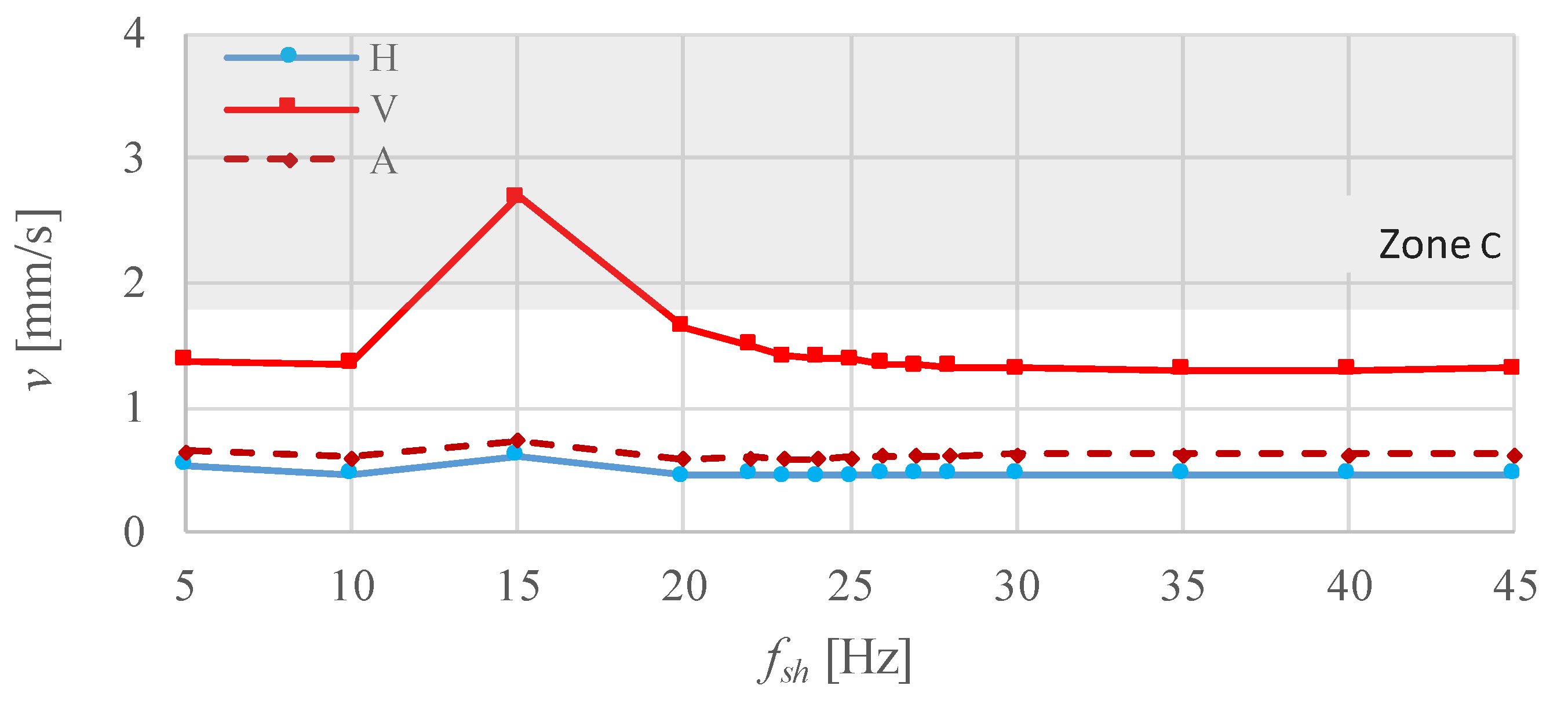
4.2. Vibration under NoLoad

This subsection presents the results of investigations for the LSPMSM coupled with an unloaded DC machine. Figure 4 and Figure 5 show the broad-band vibration velocity for subharmonics of values ush = 0.5% and ush = 1%, respectively. As mentioned in Section 1, the subharmonics of values circa 1% were reported in real power systems [1,2,3]. As shown in Figure 4 and Figure 5, the highest vibration occurred for fsh = 15 Hz. The maximal vibration velocity reached 2.70 and 3.755 mm/s for ush = 0.5% (Figure 4) and ush = 1% (Figure 5), respectively, falling into Zone C. For frequencies fsh below ~10 Hz and greater than 20 Hz, the vibration velocity was much lower, generally within the limits of Zone B. Furthermore, the vibration velocities for the supply voltage without subharmonics (reference test) were 0.739 mm/s, 0.512 mm/s and 0.634 mm/s in the vertical, horizontal, and axial directions, respectively.
The primary source of excessive vibration under power quality disturbances is tangential electromagnetic forces (based on [5,48]), interconnected with the torque pulsations. In the case of rotating machinery supplied with voltage containing SaIs, torque pulsations are chiefly caused by the flow of current SaIs through the windings (based on [35]). In practice, SaI currents produce their own rotating magnetic field, interacting with the field because of the fundamental current harmonic [28].
An exemplary waveform of the supply motor current is shown in Figure 6 for the voltage subharmonic frequency fsh = 15 Hz and value ush = 1%, with the spectrum of the current waveform presented in Figure 7. The current waveform contained a subharmonic of value Ish = 16.72% of the rated current (Irat) and an interharmonic of frequency 115 Hz and value Iih = 2.86% of Irat and some minor components of frequency 10 Hz, 20 Hz, 85 Hz, 115 Hz and value 0.7%, 1.23%, 0.74%, 3.71% of Irat, respectively. Next, Figure 8 presents the main current subharmonic component versus its frequency fsh. The characteristic generally decreased as the frequency fsh rose, and did not contain current peaks, characteristic of rigid-body resonance of the rotating mass [5,35,36,37]. For example, for the same power train (LSPMSM coupled with the unloaded DC machine) and positive-sequence subharmonics, the resonant peak occurred at the frequency fsh = 10 Hz [36]. In practice, for this fsh, the current subharmonic was higher by ~50% than those for fsh = 5 and 15 Hz [36].
Although the observed vibration (Figure 4 and Figure 5) was indirectly induced by the flow of the distorted current, the collocation of Figure 4, Figure 5 and Figure 8 shows that the vibration velocity was not directly interconnected with the value of current subharmonics. In practice, the vibration severity “directly depends on the mechanical behavior of the motor structure and the possibility of a resonance condition... on the structure of an entire unit or on the motor components” [48].
In summary, for the investigated motor, the negative-sequence voltage subharmonics resulted in high vibration around the resonant frequency of the mechanical structure, while for other frequencies, the vibration was comparatively low. Rigid-body resonance of the rotating mass was not observed.

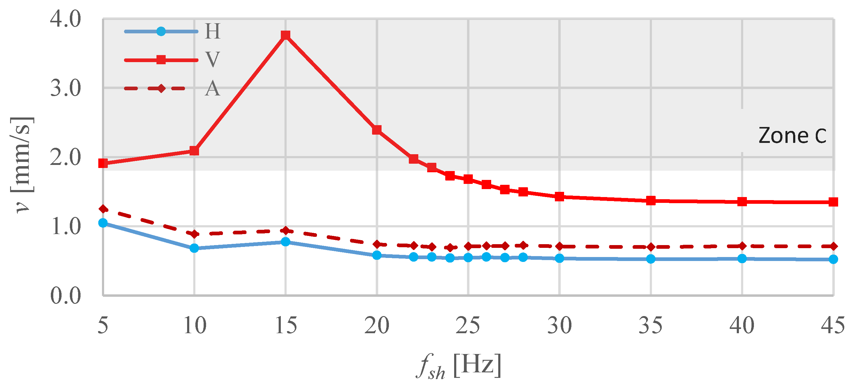
4.3. Vibration under Rated Load

This subsection presents the results of the investigation on the vibration velocity under full load. Similarly to the previous subsection, the appropriate experimental investigations were carried out for the subharmonic of values ush = 0.5% and 1%. Additionally, the reference test was performed for the supply voltage without subharmonics; the measured vibration velocities were 1.136 mm/s, 0.825 mm/s, and 1.049 mm/s for the vertical, horizontal, and axial directions, respectively.
Figure 9 and Figure 10 show the characteristics of the broad-band vibration velocity versus the subharmonic frequency fsh. The maximal vibration velocity reached 5.058 mm/s for ush = 0.5% (Figure 9) and 7.344 mm/s for ush = 1% (Figure 10). Notably, these values were considerably greater than under no load (see Section 4.2). In contrast to the no-load condition, the vibration velocity took high values for the wide frequency range. For both the subharmonic values, almost all measurement points (except the vibration velocity for the frequency fsh = 45 Hz) corresponded to Zones C and D. Of note, in Figure 9 and Figure 10, the maximal vibration velocity occurred for the frequency fsh = 25 Hz, while for no load, the highest vibration velocity was observed for the frequency fsh = 15 Hz. According to the authors’ experience, the vibration under no load and full load significantly diverges (e.g., [5,35,36,37]). The differences may result from the non-linear coupling properties, among others. In particular, the coupling stiffness depends on the twist angle, which, in practice, is the carried torque. In addition, the anti-torque produced by the DC generator causes a change in the stress distribution of the structural components. At the same time, the vibration is extremely sensitive to the variation in any agents influencing the mechanical structure; a seemingly negligible change may significantly affect the vibration.
In summary, at full load, the measured vibration velocity was significantly higher than at no load. Additionally, for the investigated motor, the maximal vibration occurred for other frequencies at full and no load. A detailed analysis of the impact of load variation on the vibration will be a subject of future research.

5. Discussion

Voltage subharmonics exert a harmful impact on various electrical equipment, especially on rotating machinery. Among others, voltage subharmonics cause local saturations of the magnetic circuits, increased power losses and windings temperatures, torque pulsations, and unacceptable vibrations. Previous works on low-voltage machinery under subharmonics [5,28,31,32,33,34,35,36,37] focused on the negative phenomena appearing in the cage induction motor. The effects of voltage subharmonics on the LSPMSM were investigated in the authors’ studies [36,37], but they were limited to positive-sequence subharmonics. In fact, both positive- and negative-sequence voltage subharmonics may occur in the power system, independent of their frequency (order) [21].
The previous studies on the rotating machinery under SaIs reported excessive vibration for no-load conditions, while in the load conditions, the vibration was generally moderate [5,35,36,37]. On the contrary, the results of the investigations presented in this work show that unacceptable vibration may occur for both no and full load. For the full-load condition with subharmonic values reported in real power systems (~1% [1,2,3]), the measured vibration reaches an extremely high level–the maximal vibration velocity exceeds the boundaries of the evaluation Zone D by 60%. In addition, for the subharmonics value ush = 0.5%, the vibration velocity falls into Zone D, the region where machine damage can occur [46]. Furthermore, for no load, the measured vibration velocity was appreciably lower than under full load. For both the considered subharmonic values—ush = 0.5% and 1%—the maximal vibration velocity corresponded to Zone C. In practice, the vibration was undue for long-time machine operation.
To protect energy receivers against malfunctions, strict limits on voltage subharmonics should be introduced into power quality standards. The determination of the appropriate permissible limits requires vibration investigations on rotating machinery. The research should include LSPMSMs of various manufacturers, rated powers, and numbers of poles under both positive- and negative-sequence voltage subharmonics.

6. Conclusions

Previous works [5,35,36,37] reported excessive vibration of the rotating machinery under subharmonics in the no-load conditions, while the vibration observed under full load was generally comparatively low. In contrast, for the investigated LSPMSM under negative-sequence subharmonics, the vibration at full load was much more significant than at no load. For the full-load condition with voltage subharmonics values significantly less than observed in real power systems, the maximal vibration velocity exceeds the threshold value of the evaluation Zone D [46]. Additionally, for the no-load condition, the vibration velocity was unacceptable, corresponding to Zone C. To protect energy consumers from malfunctions caused by subharmonics, their limits should be introduced into power quality standards and rules. Determination of the permissible subharmonic levels requires comprehensive investigations of various electrical equipment, including LSPMSMs.

Author Contributions

Conceptualization, P.G., M.P. and D.H.; methodology, M.P. and D.H.; formal analysis, M.P. and A.M.; investigation, M.P., A.M. and D.H.; writing—original draft preparation, P.G.; supervision, P.G. All authors have read and agreed to the published version of the manuscript.

Funding

This research received no external funding.

Data Availability Statement

Data are contained within the article.

Conflicts of Interest

The authors declare no conflicts of interest.

Abbreviations

Aaxial
ACalternating current
B&KBruel&Kjear
DCdirect current
DCSdouble-frequency conversion system
Hhorizontal
LSPMSMline-start permanent magnet synchronous motor
SaIssubharmonics and interharmonics
Vvertical
List of Symbols
f1fundamental frequency
fhharmonic frequency
fihinterharmonic frequency
fmvoltage fluctuations frequency
foDCS output frequency
frDC link ripples frequency
fshsubharmonic frequency
ggravitational acceleration
Iihcurrent interharmonic
Iratrated current
Ishcurrent subharmonic
mzero or natural number
nnatural number
p1pulse number of the rectifier
p2pulse number of the inverter
Sratrated apparent power
ushvoltage subharmonic (related to the fundamental component)
xddirect-axis synchronous reactance
xqquadrature-axis synchronous reactance

References

  1. Barros, J.; de Apraiz, M.; Diego, R.I. Measurement of subharmonics in power voltages. In Proceedings of the Power Tech 2007 IEEE Conference, Lausanne, Switzerland, 1–5 July 2007; pp. 1736–1740. [Google Scholar] [CrossRef]
  2. Nassif, A.B. Assessing the impact of harmonics and interharmonics of top and mudpump variable frequency drives in drilling rigs. IEEE Trans. Ind. Appl. 2019, 55, 5574–5583. [Google Scholar] [CrossRef]
  3. Xie, X.; Zhang, X.; Liu, H.; Liu, H.; Li, Y.; Zhang, C. Characteristic analysis of subsynchronous resonance in practical wind farms connected to series-compensated transmissions. IEEE Trans. Energy Convers. 2017, 32, 1117–1126. [Google Scholar] [CrossRef]
  4. Crotti, G.; D’Avanzo, G.; Letizia, P.S.; Luiso, M. Measuring harmonics with inductive voltage transformers in presence of subharmonics. IEEE Trans. Instrum. Meas. 2021, 70, 1–13. [Google Scholar] [CrossRef]
  5. Gnaciński, P.; Pepliński, M.; Murawski, L.; Szeleziński, A. Vibration of induction machine supplied with voltage containing subharmonics and interharmonics. IEEE Trans. Energy Convers. 2019, 34, 1928–1937. [Google Scholar] [CrossRef]
  6. Zhang, S.; Kang, J.; Yuan, J. Analysis and suppression of oscillation in V/F controlled induction motor drive systems. IEEE Trans. Transp. Electrif. 2022, 8, 1566–1574. [Google Scholar] [CrossRef]
  7. Bollen, M.H.J.; Gu, I.Y.H. Origin of power quality variations. In Signal Processing of Power Quality Disturbances; Wiley: New York, NY, USA, 2006; pp. 41–162. [Google Scholar]
  8. Arkkio, A.; Cederström, S.; Awan, H.A.A.; Saarakkala, S.E.; Holopainen, T.P. Additional losses of electrical machines under torsional vibration. IEEE Trans. Energy Convers. 2018, 33, 245–251. [Google Scholar] [CrossRef]
  9. Avdeev, B.A.; Vyngra, A.V.; Chernyi, S.G.; Zhilenkov, A.A.; Sokolov, S.S. Evaluation and procedure for estimation of interharmonics on the example of non-sinusoidal current of an induction motor with variable periodic load. IEEE Access 2021, 9, 158412–158419. [Google Scholar] [CrossRef]
  10. Bongini, L.; Mastromauro, R.A. Subsynchronous torsional interactions and start-up issues in oil & gas plants: A real case study. In Proceedings of the AEIT International Annual Conference, Firenze, Italy, 18–20 September 2019; pp. 1–6. [Google Scholar] [CrossRef]
  11. Čerňan, M.; Müller, Z.; Tlustý, J.; Valouch, V. An improved SVC control for electric arc furnace voltage flicker mitigation. Int. J. Electr. Power Energy Syst. 2021, 129, 106831. [Google Scholar] [CrossRef]
  12. Djurović, S.; Vilchis-Rodriguez, D.S.; Smith, A.C. Supply induced interharmonic effects in wound rotor and doubly-fed induction generators. IEEE Trans. Energy Convers. 2015, 30, 1397–1408. [Google Scholar] [CrossRef]
  13. Gudiño-Ochoa, A.; Jalomo-Cuevas, J.; Molinar-Solís, J.E.; Ochoa-Ornelas, R. Analysis of Interharmonics Generation in Induction Motors Driven by Variable Frequency Drives and AC Choppers. Energies 2023, 16, 5538. [Google Scholar] [CrossRef]
  14. Schramm, S.; Sihler, C.; Song-Manguelle, J.; Rotondo, P. Damping torsional interharmonic effects of large drives. IEEE Trans. Power Electron. 2010, 25, 1090–1098. [Google Scholar] [CrossRef]
  15. Soltani, H.; Davari, P.; Zare, F.; Loh, P.C.; Blaabjerg, F. Characterization of input current interharmonics in adjustable speed drives. IEEE Trans. Power Electron. 2017, 32, 8632–8643. [Google Scholar] [CrossRef]
  16. Testa, A.; Akram, M.F.; Burch, R.; Carpinelli, G.; Chang, G.; Dinavahi, V.; Hatziadoniu, C.; Grady, W.M.; Gunther, E.; Halpin, M.; et al. Interharmonics: Theory and modeling. IEEE Trans. Power Deliv. 2007, 22, 2335–2348. [Google Scholar] [CrossRef]
  17. Testa, A.; Langella, R. Power system subharmonics. In Proceedings of the IEEE Power Engineering Society General Meeting, San Francisco, CA, USA, 16 June 2005; pp. 2237–2242. [Google Scholar] [CrossRef]
  18. Umadevi, A.; Lakshminarasimman, L.; Sakthivel, A. Optimal design of shunt active power filter for mitigation of interharmonics in grid tied photovoltaic system. Electr. Power Syst. Res. 2023, 220, 109232. [Google Scholar] [CrossRef]
  19. Uz-Logoglu, E.; Salor, O.; Ermis, M. Online characterization of interharmonics and harmonics of ac electric arc furnaces by multiple synchronous reference frame analysis. IEEE Trans. Ind. Appl. 2016, 52, 2673–2683. [Google Scholar] [CrossRef]
  20. Verma, N.; Kumar, N.; Gupta, S.; Malik, H.; García Márquez, F.P. Review of sub-synchronous interaction in wind integrated power systems: Classification, challenges, and mitigation techniques. Prot. Control Mod. Power Syst. 2023, 8, 17. [Google Scholar] [CrossRef]
  21. Zhang, D.; Xu, W.; Liu, Y. On the phase sequence characteristics of interharmonics. IEEE Trans. Power Deliv. 2005, 20, 2563–2569. [Google Scholar] [CrossRef]
  22. Zhong, Q.; Qiu, Y.; Zhao, Y.; Li, H.; Wang, G.; Wen, F. Interharmonic analysis model of photovoltaic grid-connected system with extended dynamic phasors. J. Mod. Power Syst. Clean Energy 2021, 9, 1540–1547. [Google Scholar] [CrossRef]
  23. Tripp, H.; Kim, D.; Whitney, R. A comprehensive cause analysis of a coupling failure induced by torsional oscillations in a variable speed motor. In Proceedings of the 22nd Turbomachinery Symposium, Dallas, TX, USA, 14–16 September 1993; Texas A&M University, Turbomachinery Laboratories: College Station, TX, USA, 1993; pp. 17–24. [Google Scholar] [CrossRef]
  24. Gutierrez-Ballesteros, E.; Rönnberg, S.; Gil-de-Castro, A. Characteristics of voltage fluctuations induced by household devices and the impact on LED lamps. Int. J. Electr. Power Energy Syst. 2022, 141, 108158. [Google Scholar] [CrossRef]
  25. Kuwalek, P. Estimation of parameters associated with individual sources of voltage fluctuations. IEEE Trans. Power Deliv. 2020, 36, 351–361. [Google Scholar] [CrossRef]
  26. Kuwalek, P. Selective Identification and Localization of Voltage Fluctuation Sources in Power Grids. Energies 2021, 14, 6585. [Google Scholar] [CrossRef]
  27. Gallo, D.; Landi, C.; Langella, R.; Testa, A. Limits for low frequency interharmonic voltages: Can they be based on the flickermeter use. In Proceedings of the 2005 IEEE Russia Power Tech, St. Petersburg, Russia, 27–30 June 2005; pp. 1–7. [Google Scholar] [CrossRef]
  28. Tennakoon, S.; Perera, S.; Robinson, D. Flicker attenuation—Part I: Response of three-phase induction motors to regular voltage fluctuations. IEEE Trans. Power Deliv. 2008, 23, 1207–1214. [Google Scholar] [CrossRef]
  29. Michalski, M.; Wiczyński, G. Flicker Dependency on Voltage Fluctuation at Frequencies Greater Than Power Frequency. In Proceedings of the 2022 20th International Conference on Harmonics & Quality of Power (ICHQP), Naples, Italy, 29 May–1 June 2022; pp. 1–5. [Google Scholar] [CrossRef]
  30. Yu, Y.; Zhao, W.; Chen, L.; Wang, Q.; Huang, S. Power measurement accuracy analysis in the presence of interharmonics. Measurement 2020, 154, 107484. [Google Scholar] [CrossRef]
  31. Ghaseminezhad, M.; Doroudi, A.; Hosseinian, S.H.; Jalilian, A. High torque and excessive vibration on the induction motors under special voltage fluctuation conditions. COMPEL Int. J. Comput. Math. Electr. Electron. Eng. 2021, 40, 822–836. [Google Scholar] [CrossRef]
  32. Ghaseminezhad, M.; Doroudi, A.; Hosseinian, S.H.; Jalilian, A. Analysis of voltage fluctuation impact on induction motors by an innovative equivalent circuit considering the speed changes. IET Gener. Transm. Distrib. 2017, 11, 512–519. [Google Scholar] [CrossRef]
  33. Ghaseminezhad, M.; Doroudi, A.; Hosseinian, S.H.; Jalilian, A. An investigation of induction motor saturation under voltage fluctuation conditions. J. Magn. 2017, 22, 306–314. [Google Scholar] [CrossRef]
  34. Ghaseminezhad, M.; Doroudi, A.; Hosseinian, S.H.; Jalilian, A. Analytical field study on induction motors under fluctuated voltages. Iran. J. Electr. Electron. Eng. 2021, 17, 1620. [Google Scholar] [CrossRef]
  35. Gnaciński, P.; Hallmann, D.; Muc, A.; Klimczak, P.; Pepliński, M. Induction motor supplied with voltage containing symmetrical subharmonics and interharmonics. Energies 2022, 15, 7712. [Google Scholar] [CrossRef]
  36. Gnaciński, P.; Muc, A.; Pepliński, M. Influence of voltage subharmonics on line start permanent magnet synchronous motor. IEEE Access 2021, 9, 164275–164281. [Google Scholar] [CrossRef]
  37. Gnaciński, P.; Muc, A.; Pepliński, M. Line start permanent magnet synchronous motor supplied with voltage containing subharmonics. Sci. J. Marit. Univ. Szczec. 2023, 74, 28–34. [Google Scholar] [CrossRef]
  38. EN Standard 50160, 2010/A2:2019; Voltage Characteristics of Electricity Supplied by Public Distribution Network. CELENEC: Brussels, Belgium, 2019.
  39. IEEE Std 519™-2022; IEEE Standard for Harmonic Control in Electric Power Systems. Transmission and Distribution Committee of the IEEE Power and Energy Society. The Institute of Electrical and Electronics Engineers, Inc.: New York, NY, USA, 2022; pp. 10016–15997.
  40. Kazakbaev, V.; Paramonov, A.; Dmitrievskii, V.; Prakht, V.; Goman, V. Indirect Efficiency Measurement Method for Line-Start Permanent Magnet Synchronous Motors. Mathematics 2022, 10, 1056. [Google Scholar] [CrossRef]
  41. Pechlivanidou, M.S.; Kladas, A.G. Comparison of alternate LSPMSM topologies considering both transient and steady-state operating characteristics. In Proceedings of the 2019 IEEE Workshop on Electrical Machines Design, Control and Diagnosis, Athens, Greece, 22–23 April 2019; pp. 40–45. [Google Scholar] [CrossRef]
  42. Singh, R.R.; Raj, C.T.; Palka, R.; Indragandhi, V.; Wardach, M.; Paplicki, P. Energy optimal intelligent switching mechanism for induction motors with time varying load. In Proceedings of the IOP Conference Series: Materials Science and Engineering, Galati, Romania, 22–24 September 2020; Volume 906, p. 012017. [Google Scholar] [CrossRef]
  43. Thirugnanasambandam, M.; Hasanuzzaman, M.; Saidur, R.; Ali, M.B.; Rajakarunakaran, S.; Devaraj, D.; Rahim, N.A. Analysis of electrical motors load factors and energy savings in an Indian cement industry. Energy 2011, 36, 4307–4314. [Google Scholar] [CrossRef]
  44. ISO Standard 20816-1; Mechanical Vibration—Measurement and Evaluation of Machine Vibration—Part 1: General Guidelines. ISO: Genova, Switzerland, 2016.
  45. Ho, S.L.; Fu, W.N. Analysis of indirect temperature-rise tests of induction machines using time stepping finite element method. IEEE Trans. Energy Convers. 2001, 16, 55–60. [Google Scholar] [CrossRef]
  46. Tarasiuk, T. Estimator—Analyzer of power quality: Part I—Methods and algorithms. Measurement 2011, 44, 238–247. [Google Scholar] [CrossRef]
  47. ISO Standard 10816-1; Mechanical Vibration—Evaluation of Machine Vibration by Measurements on Non-Rotating Parts—Part 1: General Guidelines. ISO: Genova, Switzerland, 1995.
  48. Tsypkin, M. The origin of the electromagnetic vibration of induction motors operating in modern industry: Practical experience—Analysis and diagnostics. IEEE Trans. Ind. Appl. 2017, 53, 1669–1676. [Google Scholar] [CrossRef]
Figure 1. Investigated motor and accelerometer.
Energies 17 00091 g001
Figure 2. Simplified diagram of the measurement stand.
Energies 17 00091 g002
Figure 3. Flowchart of the vibration measurement.
Energies 17 00091 g003
Figure 4. Measured broad-band vibration velocity in the horizontal (H), vertical (V), and axial (A) directions versus the voltage subharmonic frequency for subharmonic value ush = 0.5%.
Energies 17 00091 g004
Figure 5. Measured broad-band vibration velocity in the horizontal (H), vertical (V), and axial (A) directions versus the voltage subharmonic frequency for subharmonic value ush = 1%.
Energies 17 00091 g005
Figure 6. Measured current waveform for the subharmonic of frequency fsh = 15 Hz and value ush = 1%.
Energies 17 00091 g006
Figure 7. Spectrum of the current waveform presented in Figure 6. The frequency components are related to the rated current.
Energies 17 00091 g007
Figure 8. Measured current subharmonics versus their frequency for subharmonic value ush = 1%, related to the rated current.
Energies 17 00091 g008
Figure 9. Measured broad-band vibration velocity in the horizontal (H), vertical (V), and axial (A) directions versus the voltage subharmonic frequency for subharmonic value ush = 0.5%.
Energies 17 00091 g009
Figure 10. Measured broad-band vibration velocity in the horizontal (H), vertical (V), and axial (A) directions versus the voltage subharmonic frequency for subharmonic value ush = 1%.
Energies 17 00091 g010
Table 1. Nameplate Data of the Investigated Motor WQuattro L100L-04.
ParameterValue
Rated power (kW)3
Rated frequency (Hz)50
Rated voltage (V)400
Rated current (A)5.84
Rated power factor (−)0.82
Rated rotational speed (rpm)1500
ManufacturerWEG Industries
Disclaimer/Publisher’s Note: The statements, opinions and data contained in all publications are solely those of the individual author(s) and contributor(s) and not of MDPI and/or the editor(s). MDPI and/or the editor(s) disclaim responsibility for any injury to people or property resulting from any ideas, methods, instructions or products referred to in the content.

