Article

Boil-Off Gas Generation in Vacuum-Jacketed Valve Used in Liquid Hydrogen Storage Tank

1
Department of Mechanical Engineering, Dong-A University, Busan 49315, Republic of Korea
2
Daechang Solution, Co., Ltd., Busan 46741, Republic of Korea
*
Author to whom correspondence should be addressed.
Energies 2024, 17(10), 2341; https://doi.org/10.3390/en17102341
Submission received: 3 April 2024 / Revised: 5 May 2024 / Accepted: 9 May 2024 / Published: 13 May 2024
(This article belongs to the Topic Advanced Heat and Mass Transfer Technologies)

Abstract

:
The boiling point of liquid hydrogen is very low, at −253 °C under atmospheric pressure, which causes boil-off gas (BOG) to occur during storage and transport due to heat penetration. Because the BOG must be removed through processes such as re-liquefaction, venting to the atmosphere, or incineration, related studies are required to estimate the heat transfer of storage and transport devices and to improve insulation to reduce BOG generation. In this study, a vaporization analysis was performed on a vacuum-jacketed valve used in liquid hydrogen storage and transport devices to calculate the amount of BOG generation considering the flow characteristics at the vena contracta and the saturation temperature. At a pressure of 1 bar in the liquid hydrogen storage tank, the maximum fluid flow velocity and minimum static pressure occurred at the vena contracta, with values of 62.9 m/s and −0.4 bar, respectively, and the BOG generation rate was estimated as 0.132 m3/h, where the saturation temperature was minimized at 19.3 K. Furthermore, through case studies, when the pressure in the liquid hydrogen storage tank increased to 1.5 and 2 bar, the static pressure and saturation temperature decreased, and the BOG generation rate increased to 0.221 and 0.283 m3/h, respectively.

1. Introduction

The boiling point of liquid hydrogen is very low at 20 K (−253 °C) under atmospheric pressure, which leads to the generation of boil-off gas (BOG) due to heat penetration during storage and transport processes [1]. The BOG increases the internal pressure of storage and transport devices, potentially leading to explosions in severe cases. Various methods can be employed to treat the BOG, including re-liquefaction, release into the atmosphere, or incineration. However, re-liquefaction not only consumes additional energy but also presents challenges in completely removing the BOG. There are also inevitable economic losses associated with releasing BOG into the atmosphere or incinerating it. Therefore, related research is needed to estimate the heat transfer characteristics of liquid hydrogen storage and transport devices and to improve thermal insulation to reduce the generation of BOG.
Smith et al. [2] investigated the rate of BOG generation for a conceptual liquid hydrogen fuel carrier with a capacity of 173,600 m3 using numerical and empirical formulas based on thermodynamics. The rate of BOG generation was influenced by the external weather conditions, speed of the fuel carrier, insulation thickness of the storage tank, and sloshing and re-liquefaction unit installed in the fuel carrier. The obtained results showed that the insulation thickness should be between 1.04 and 6.62 times greater, and the sloshing effect occurred twice as much compared to a corresponding LNG carrier with the same rate of BOG generation. Furthermore, the re-liquefaction unit required a 1.73 times larger capacity than that of the LNG carrier. Al Ghafri et al. [3] proposed the superheated vapor (SHV) model based on the liquid–vapor saturation state of liquid hydrogen. The SHV model was implemented in BoilFAST 1.1.0, a free software package for modeling boil-off production. The proposed model, applied to a liquid hydrogen storage tank, was verified by comparing experimental tests conducted in three national laboratories. The BoilFAST simulations showed good agreement with the experimental results. The authors concluded that the SHV model offered a reasonable estimation of BOG generation in the liquid hydrogen storage tank. Oh et al. [4] calculated numerically the generation of BOG in a vacuum-insulated storage tank filled with liquid hydrogen. To take account for phase changes in the liquid hydrogen, the Lee model [5] was applied, and the calculated BOG was compared with the results of previous studies. The BOG decreased to 1/12 or less depending on the vacuum levels in the vacuum insulation when the vacuum level changed from 10−1 to 10−3 torr. Thereafter, at vacuum levels up to 10−4 torr, the decrease in the BOG was slightly less than 5%. Therefore, maintaining the vacuum level at 10−3 torr was observed to be the most efficient. Seo et al. [6] evaluated the relationship between sloshing and the generation of BOG inside liquid hydrogen storage tanks, considering the direction of gravity and filling rate. The sloshing was observed to be more active when the direction of gravity changed from vertical, accompanied by an increase in heat flux and BOG generation. They found that a lower filling rate resulted in a higher proportion of vaporized liquid hydrogen and identified an interaction between the filling rate and the direction of gravity. Lee et al. [7] conducted a thermal analysis and experiments on vacuum-insulated bellows and joint-type pipes to compare and verify the generation of BOG. The results from the analysis and experiments were in agreement within 5%. They found that the joint-type pipe exhibited higher stress and a higher BOG generation rate compared to the bellows-type pipe.
On reviewing the aforementioned studies, they primarily focused on numerically evaluating the amount of BOG generated by heat penetration and sloshing in liquid hydrogen storage tanks and pipes. However, there is a lack of research on the BOG generated from valves used for opening and controlling the flow rate of liquid hydrogen. Unlike storage tanks, valves do not retain liquid hydrogen for extended periods, so it might be assumed that the BOG generation would be similar to that of pipes. However, valves have more complex flow paths compared to pipes, which can lead to an environment conducive to vaporization due to turbulence and an additional pressure drop.
In this study, a vaporization analysis was conducted on a vacuum-jacketed valve used in liquid hydrogen storage and transport devices. Using the commercial software ANSYS Fluent 17.2 and its user-defined function (UDF), the fluid flow characteristics including changes in the saturation temperatures were estimated at the point of sudden fluid flow change, known as the vena contracta, and then the amount of BOG generated was calculated. Case studies were carried out to consider the correlation between the pressures in the liquid hydrogen storage tank and the BOG generation.

2. Vacuum-Jacketed Valve

Figure 1 shows the vacuum-jacketed valve provided by a domestic company, which is utilized in liquid hydrogen storage and transport devices. It comprises a globe valve for fluid flow control with inlet and outlet diameters of 2.1 inches. The valve is composed of a valve body, stem, and jacket to protect against heat penetration from the outside, along with a seat and bellows to prevent internal and external leakage. The valve body, stem, and jacket components are made of SUS 316L, which exhibits sufficient ductility in the very low temperatures of liquid hydrogen environments. Other components, such as the seat and bellows, are made of polytetrafluoroethylene (PTFE) and ethylene propylene diene monomer (EPDM), respectively, to prevent internal and external leakage. The properties of each material are summarized in Table 1.

3. Vaporization Analysis

3.1. Mathematical Model

To numerically calculate the amount of boil-off gas (BOG) generated in liquid hydrogen passing through the vacuum-jacketed valve, inter-phase mass transfer models related to phase change must be applied. Representative models are already known as the Lee, Nichita, and Sun models [5,8,9]. Among them, the Sun model exhibits the highest accuracy when the ratio of the density in the liquid to gaseous phases is below 100. Meanwhile, the Lee model yields higher accuracy and reliability in obtained results with a more accurately estimating its relaxation coefficient. Because the density of liquid hydrogen is approximately 800 times higher than that of gaseous hydrogen, this study estimated the relaxation coefficient, known as an empirical constant, and calculated the phase change in the liquid hydrogen. The vapor transport equation for constructing the Lee model is as follows:
t α v ρ v + α v ρ v V = m ˙ l v m ˙ v l
where α v , ρ v , and V are the volume fraction, density, and velocity of gaseous hydrogen, respectively. m ˙ l v and m ˙ v l denote the mass of liquid hydrogen vaporized and gaseous hydrogen condensed per unit volume and time, respectively.
Based on the vapor transport equation, taking into account the influence of gas on the interface and the saturation temperature, it is possible to construct the Lee model for vaporization and condensation. The equations required for the Lee model are as follows:
m ˙ l v = R α l ρ l ( T l T s a t ) T s a t
m ˙ v l = R α v ρ v ( T s a t T v ) T s a t
R = 6 d b β M 2 π R T s a t H ( α v ρ v ρ l ρ v )
The Lee model is composed of the mass of liquid or gas within a control volume, the difference between the fluid temperature and the saturation temperature T s a t , and the empirical constant known as the relaxation coefficient R . T s a t can be expressed as a function of the absolute pressure P , presenting the temperature at which the vaporization of the liquid hydrogen begins, as shown in the following equation:
l o g T s a t = 1.497 + 0.209 log P + 0.021 l o g P 2
R is a constant related to the rate of phase change, derived through a comparison with results obtained from previous studies. In this study, a vaporization analysis was conducted using a commercial software of ANSYS Fluent, employing the same model and conditions as the self-pressurization experiment conducted by Aydelott [10], and the obtained results were compared. The rate of pressure increase per minute obtained from the vaporization analysis was 566 Pa/s, which closely matched the experimental results of 563 Pa/s. The R obtained during the analysis process was calculated to be 0.000788 1/s.
In the vaporization and condensation of hydrogen, the molecular bonding state changes, accompanied by the inflow and outflow of thermal energy. During vaporization, liquid hydrogen absorbs thermal energy, whereas during condensation, gaseous hydrogen releases thermal energy, which enable the phase change. In this case, the thermal energy S is calculated based on the mass of the fluid undergoing the phase change and its latent heat, which can be expressed as follows:
S = m ˙ H
where H presents the latent heat with a magnitude of 443,000 J/kg. Ref. [11] m ˙ is calculated using the Lee model, and it is multiplied by H to evaluate the thermal energy absorbed and released during the phase change.

3.2. Grid Configuration and Load and Boundary Conditions

The vaporization analysis was performed to compare the BOG generation between the vacuum-jacketed pipe and valve on models with identical diameters of the inlet and outlet. The Lee model was applied using a user-defined function (UDF) in ANSYS Fluent to provide an accurate estimation of the evaporative latent heat and saturation temperature in Equation (5). The grid models for the vacuum-jacketed pipe and valve for the vaporization analysis are shown in Figure 2, consisting of 1,795,282 and 7,539,844 tetrahedral elements, respectively.
The load and boundary conditions were considered for a liquid hydrogen storage tank with a maximum gauge pressure of 2 bar [12]. At the inlet of the vacuum-jacketed pipe and valve, total pressures of 1, 1.5, and 2 bar were applied, while a static pressure of 0 bar was imposed at the outlet. A heat transfer coefficient of 10 W / m 2 K was applied to account for heat transfer due to natural convection. Inside the jacket, only conductive heat transfer was taken into account to reduce the excessive computational burden associated with including a vacuum layer, where a thermal conductivity of 0.0014 W / m K [13] was applied. All the load and boundary conditions for the vaporization analysis are listed in Table 2.
To simulate the interface between liquid and gaseous hydrogen, the volume of fluid was applied from the Eulerian perspective, in which the pressure-based solver and the algorithm of the semi-implicit method for linked equations (SIMPLE) were utilized. Momentum and energy equations were discretized using the third-order monotonic upstream-centered scheme for conservation law (MUSCL), which has been known for its accuracy on unstructured finite volumes. Pressure gradients were calculated using an interpolation method of the pressure staggering option (PRESTO), which is suitable for fluid flows with rapid pressure changes. Due to an irregular fluid flow over time caused by BOG generation, a transient fluid flow analysis was performed with a time step of 0.01 s, and the analysis was conducted for 3 s until the BOG generation reached a steady state.

4. Analysis Results

4.1. BOG Generation

The results obtained from the vaporization analysis for the vacuum-jacketed pipe and valve under the condition of 1 bar pressure in the liquid hydrogen storage tank are shown in Figure 3, Figure 4 and Figure 5. Figure 3 shows the distribution of the streamlines related to the velocity of liquid hydrogen. At the inlet of the vacuum-jacketed pipe and valve, velocities of 52.7 and 20.8 m / s , respectively, were calculated, with a maximum value of 62.9 m / s observed at the vacuum-jacketed valve. The vacuum-jacketed pipe exhibits a consistent velocity throughout the entire area, as shown in Figure 3a. Meanwhile, a vena contracta occurred in the vacuum-jacketed valve, as shown in Figure 3b, caused by the disc and seat acting as a throttle to control the fluid flow of the liquid hydrogen. At the vena contracta, the cross-sectional area of the fluid flow decreases, and the highest velocity is observed at the minimum cross-sectional area.
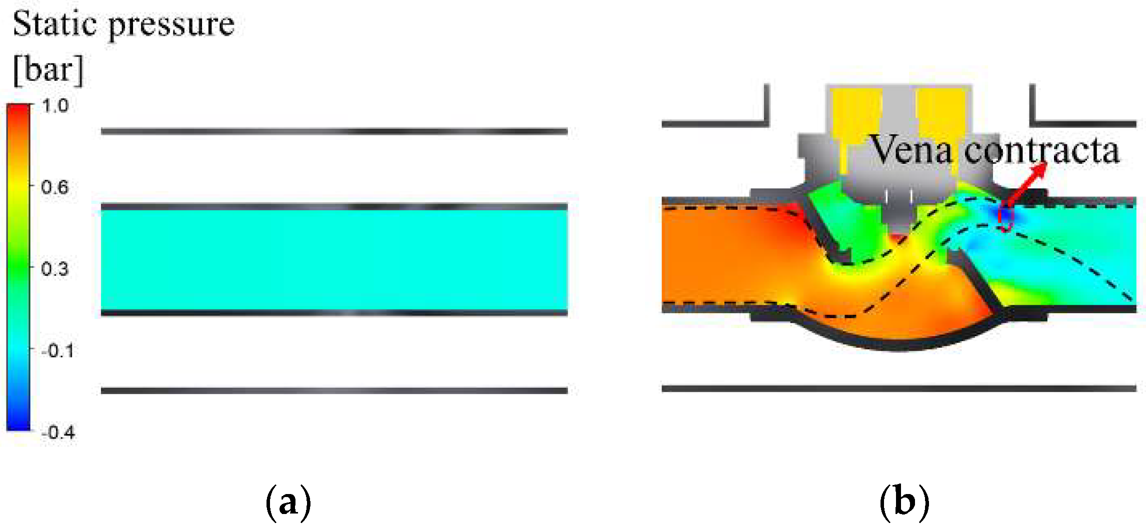
Figure 4 shows the static pressure distribution of liquid hydrogen. At the inlet of the vacuum-jacketed pipe and valve, the static pressures are 0.04 and 0.86 b a r , respectively, with the minimum static pressure of −0.4 b a r at the vena contracta of the vacuum-jacketed valve. In the vacuum-jacketed pipe, as shown in Figure 4a, there are no obstacles interfering with the fluid flow, resulting in low pressure head loss and a linear pressure distribution. However, in the vacuum-jacketed valve, as shown in Figure 4b, a vena contracta occurred due to the complex fluid flow geometry, which leads to fast fluid flow and low pressure. The decrease in static pressure with increased fluid flow velocity can be explained by Bernoulli’s principle, and the decreased static pressure causes the decrease in the saturation temperature T s a t , as described by Equation (5) in Section 3.1.
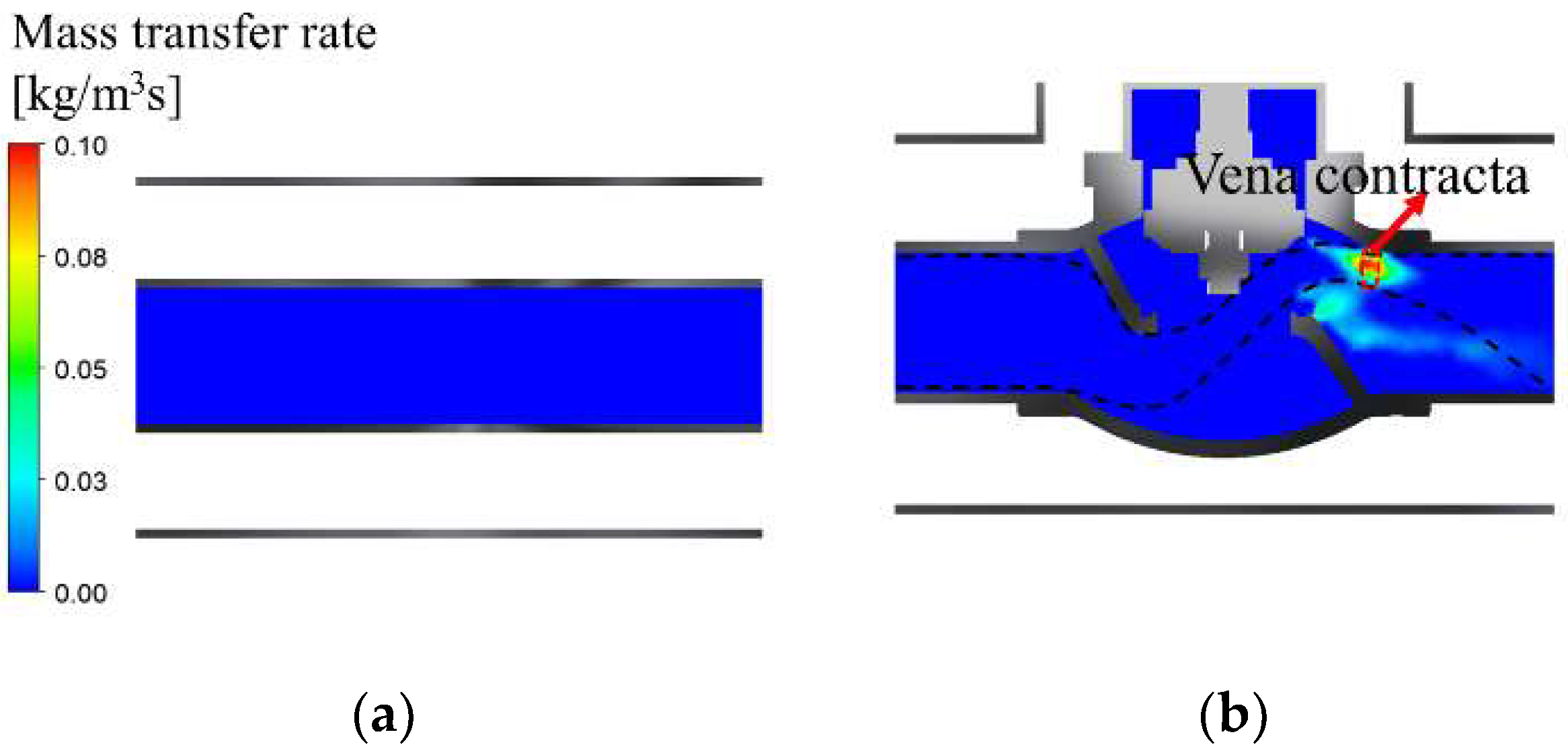
Figure 5 shows the distribution of the BOG mass per unit volume and time, where the maximum values are 0.0007 and 0.1 k g / m 3 s at the vacuum-jacketed pipe and valve, respectively. The BOG generated in the vacuum-jacketed pipe is negligibly small, whereas at the vacuum-jacketed valve, as shown in Figure 5b, it peaks at the vena contracta where the pressure and T s a t decrease.
The mass transfer rate of BOG discharging from the outlet per hour was quantitatively evaluated. In the vacuum-jacketed pipe, there was a negligible amount of BOG generation due to a high fluid flow velocity and low vaporization rate. Meanwhile, the mass transfer rate of BOG for the vacuum-jacketed valve was up to 0.0108 k g / h , which corresponds to 0.132 m 3 / h when converted to volume. Considering the time required for unloading liquid hydrogen from the storage tank at a pressure of 1 b a r , the volume of BOG generated during the unloading process can be estimated based on the results of the vaporization analysis. The estimated value could be used as data for the design of a BOG capture and re-liquefaction system.

4.2. BOG Generation Regarding Tank Pressures

To estimate the correlation between the pressure in the liquid hydrogen storage tank and the amount of BOG generated at the vacuum-jacketed valve, the rate of BOG generation at tank pressures of 1.5 and 2 bar were calculated and compared with those at the tank pressure of 1 bar. The vaporization analysis was carried out, in which the tank pressures of 1.5 and 2 bar were applied at the inlet and a static pressure of 0 bar was applied at the outlet. The results obtained from the vaporization analysis are summarized in Figure 6 and Figure 7 and Table 3.
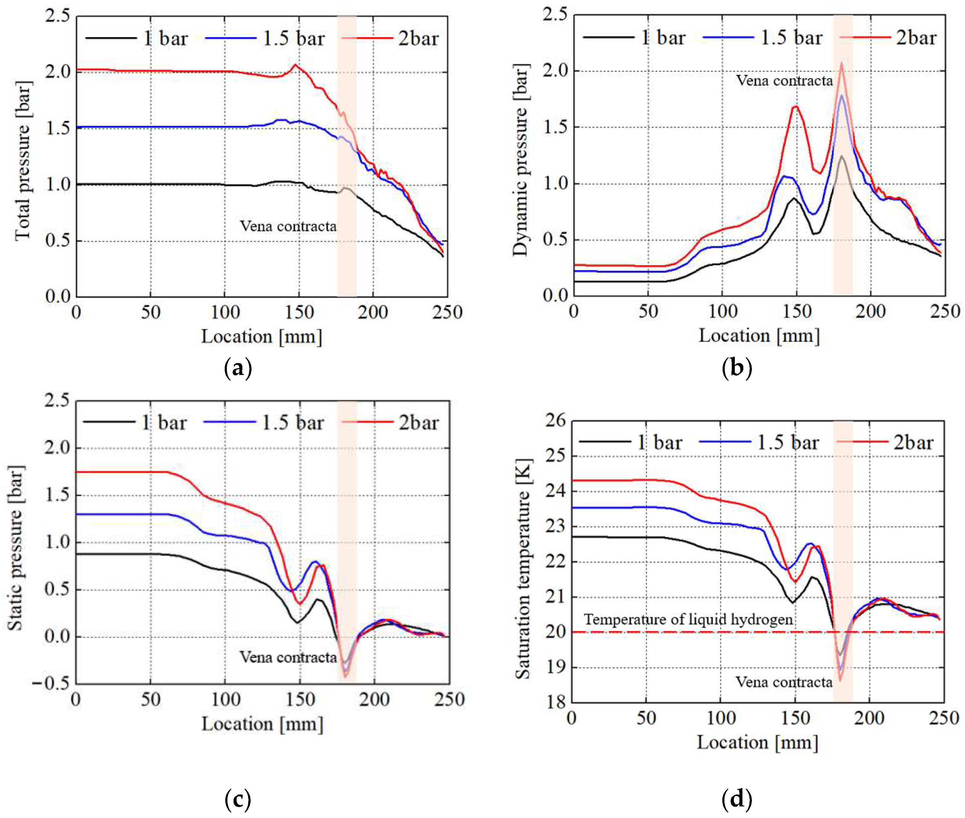
Figure 6 shows the total pressure, dynamic pressure, static pressure, and saturation temperature T s a t of the liquid hydrogen along the main fluid flow from the inlet to the outlet of the vacuum-jacketed valve, where the location of the vena contracta is denoted by the shaded area. The total pressure represents the fluid energy, where the total pressures at the inlet correspond to the tank pressures, as shown in Figure 6a. The total pressure decreases drastically as the liquid hydrogen passes through the valve body due to the dissipation effect of turbulence, which reduced the fluid energy [14]. Figure 6b,c exhibit the dynamic and static pressures, respectively, showing a negative correlation between them. The maximum dynamic pressures of 1.25, 1.79, and 2.08 bar occur at the vena contracta for tank pressures of 1, 1.5, and 2 bar, respectively, while the minimum static pressures at the same location are −0.27, −0.37, and −0.43 bar. These values, when converted to absolute pressure, are 0.74, 0.65, and 0.59 bar, respectively. Changes in the T s a t with the tank pressures, as shown in Figure 6d, exhibit similar trends to those in the static pressure. The minimum T s a t occurs at the vena contracta, and they are 19.3, 18.9, and 18.6 K for tank pressures of 1, 1.5, and 2 bar, respectively. Because the BOG mass reaches its maximum at the vena contracta where both the static pressure and T s a t are lowest, as shown in Figure 5, the changes in the BOG mass with the tank pressures are significantly influenced by the static pressure and T s a t .
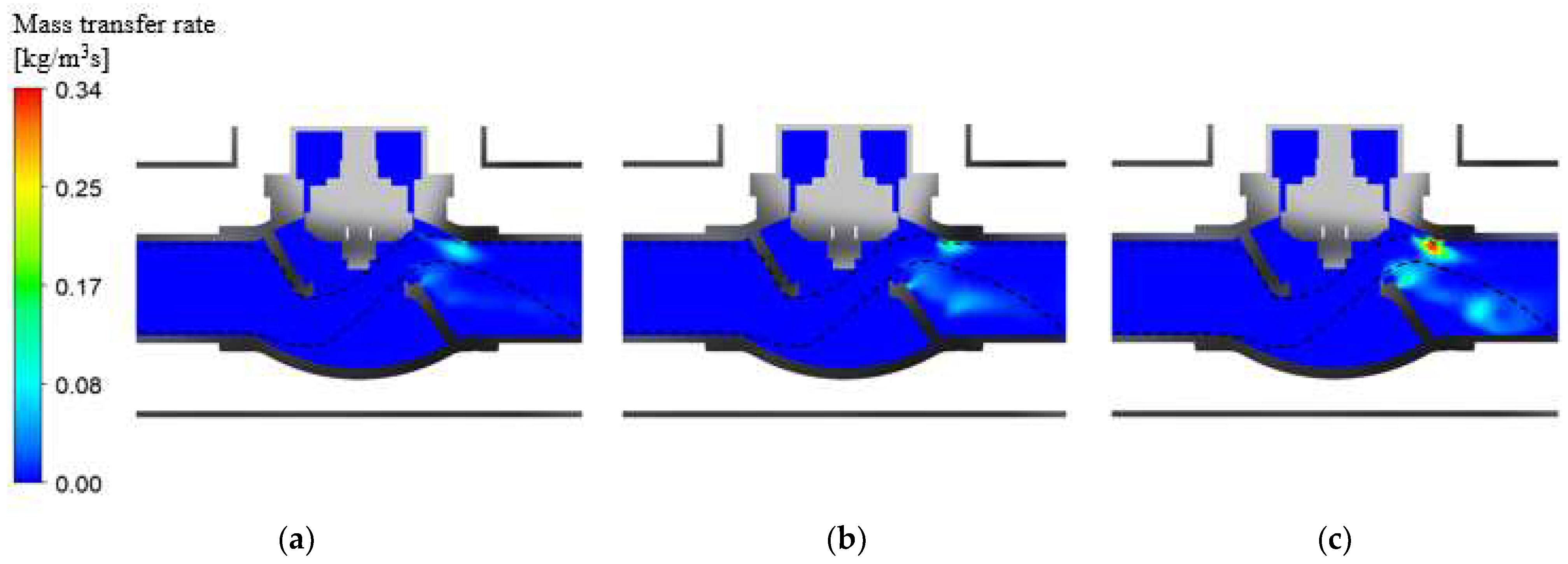
Figure 7 shows the results of the changes in the BOG mass per unit volume and time, i.e., the mass transfer rate of the BOG, regarding tank pressures. With an increase in the tank pressure, the mass transfer rate increases due to the significant decrease in the static pressure and T s a t at the vena contracta. At tank pressures of 1, 1.5, and 2 bar, the maximum values of the mass transfer rate at the vena contracta are 0.1, 0.194, and 0.337 k g / m 3 s , respectively. On the other hand, considering the total amount of BOG generated in the vacuum-jacketed valve per hour at tank pressures of 1, 1.5, and 2 bar, they are 0.0108, 0.0181, and 0.0232 k g / h , respectively. When converted to volume, these correspond to 0.132, 0.221, and 0.283 m 3 / h .
Table 3 summarizes the results, indicating that as the pressure of the liquid hydrogen storage tank increases, the amount of BOG generated per hour at the vacuum-jacketed valve also increases. However, it can be observed that the increase in the rate of BOG generation slows down after the tank pressure reaches 1.5 bar. This slowdown may be attributed to the minimum static pressure and T s a t at the vena contracta.

5. Discussion

This study is a fundamental investigation into BOG generated from valves, aiming to obtain results that ensure reproducibility and reliability and to analyze parameters influencing the BOG generation. The vaporization analysis was conducted using fixed boundary conditions. However, the fixed conditions led to several limitations as follows: In practical industrial fields, the Multi-Layer Insulation (MLI) and vacuum jacket are often used together to provide thermal insulation. However, due to a lack of material properties of the MLI, such as thermal conductivity, number of layers, and thickness, only a degree of vacuum with 10−3 Torr was taken into account in this study. The vacuum-jacketed valve can control the flow rate of liquid hydrogen depending on the opening rate. Therefore, it is necessary to evaluate the fluid flow behavior of the liquid hydrogen not only during opening and closing but also at various opening rates. However, in this study, only a 100% opening rate, indicating the fully open condition, was considered. The BOG generation can vary depending on the environments, such as the location and seasons where the vacuum-jacketed valve is installed. In this study, all these various environments were not considered. Instead, the ambient temperature was set to room temperature (300 K), and a heat transfer coefficient of 10 W/m2K was applied owing to natural convection. Due to insufficient experimental studies, the empirical constant known as the relaxation coefficient, used in the inter-phase mass transfer model, was determined using pre-existing experimental results for liquid hydrogen conducted by Aydelott (Cleveland, OH, USA) [10].
Further research on the BOG generation will be conducted, considering various parameters, such as changes in ambient temperatures, vacuum pressures, valve opening rates, and the application of the MLI. Additionally, an experimental verification test using the BOG measurement equipment of the TCHPV (Technical Center for High-Performance Valves) [15], in collaboration with the authors, will be planned.

6. Conclusions

In this study, a vaporization analysis was conducted on a vacuum-jacketed valve to calculate the amount of BOG generation, taking into account the flow characteristics and saturation temperature at the vena contracta, where the fluid flow undergoes rapid changes. Additionally, through a case study, the correlation between the pressure of the liquid hydrogen storage tank and the BOG generated at the vacuum-jacketed valve was examined.
  • Under the condition where the pressure of the liquid hydrogen storage tank is 1 bar, the maximum velocity and minimum static pressure of 62.9 m/s and −0.4 bar, respectively, occurred at the vena contracta in the vacuum-jacketed valve. The saturation temperature T s a t reached a minimum of 19.3 K, and the mass transfer rate of BOG was 0.132 m 3 / h .
  • When the tank pressures changed from 1 to 1.5 and 2 bar, the dynamic and static pressures exhibited a negative correlation, and the maximum dynamic and minimum static pressures at the vena contracta were observed to be 1.25, 1.79, and 2.08 bar and −0.27, −0.37, and −0.43 bar, respectively.
  • The T s a t due to the increase in tank pressures shows a similar trend to that of the static pressure. The minimum T s a t observed at the vena contracta was 19.3, 18.9, and 18.6 K, respectively. Because the BOG generation reached its maximum at the vena contracta where both the static pressure and T s a t were lowest, the change in the amount of BOG regarding the tank pressures was significantly influenced by the static pressure and T s a t .
  • The total amount of BOG generated in the vacuum-jacketed valve per hour at tank pressures of 1, 1.5, and 2 bar was 0.132, 0.221, and 0.283 m 3 / h , respectively. It was observed that the increase in the amount of BOG slowed down after the tank pressure reached 1.5 bar.
  • Using the vaporization analysis method proposed in this study, it is possible to estimate the amount of BOG generated during the unloading process of a liquid hydrogen storage tank. It is anticipated that this estimation can be utilized for the design of BOG capture and re-liquefaction processes.

Author Contributions

Conceptualization, S.-H.H. and H.-S.H.; methodology, S.-H.H.; validation, S.-H.H., S.-U.W. and H.-S.H.; investigation, S.-H.H., S.-U.W. and H.-S.H.; writing—original draft preparation, H.-S.H.; writing—review and editing, S.-U.W. and S.-H.H.; visualization, H.-S.H.; supervision, S.-H.H.; project administration, S.-H.H.; funding acquisition, S.-H.H. All authors have read and agreed to the published version of the manuscript.

Funding

This research was supported by the BB21plus funded by Busan Metropolitan City and Busan Techno Park.

Data Availability Statement

Data are contained within the article.

Conflicts of Interest

Author Seong-Un Woo was employed by the company Daechang Solution, Co., Ltd. The remaining authors declare that the research was conducted in the absence of any commercial or financial relationships that could be construed as a potential conflict of interest.

References

  1. Abe, A.; Nakamura, M.; Sato, I.; Uetani, H.; Fujitani, T. Studies of the Large-Scale Sea Transportation of Liquid Hydrogen. Int. J. Hydrogen Energy 1998, 23, 115–121. [Google Scholar] [CrossRef]
  2. Smith, J.R.; Gkantonas, S.; Mastorakos, E. Modelling of Boil-Off and Sloshing Relevant to Future Liquid Hydrogen Carriers. Energies 2022, 15, 2046. [Google Scholar] [CrossRef]
  3. Al Ghafri, S.Z.S.; Swanger, A.; Jusko, V.; Siahvashi, A.; Perez, F.; Johns, M.L.; May, E.F. Modelling of Liquid Hydrogen Boil-Off. Energies 2022, 15, 1149. [Google Scholar] [CrossRef]
  4. Oh, S.-J.; Kwon, J.-Y.; Jeon, K.-S.; Yoon, J.-H. A Numerical Analysis Study on the Characteristics of Evaporation in Liquid Hydrogen Tank with Vacuum Layer According to Changes in Heat Flux and Vacuum Pressure. Int. J. Hydrogen Energy 2024, 50, 542–557. [Google Scholar] [CrossRef]
  5. Lee, W.H. A Pressure Iteration Scheme for Two-Phase Flow Modeling. Multiph. Transp. Fundam. React. Saf. Appl. 1980, 1, 407–432. [Google Scholar] [CrossRef]
  6. Seo, Y.-M.; Noh, H.-W.; Ha, D.-W.; Koo, T.-H.; Ko, R.-K. Numerical Study on the Effects of Gravity Direction and Hydrogen Filling Rate on BOG in the Liquefied Hydrogen Storage Tank. J. Hydrog. New Energy 2023, 34, 342–349. [Google Scholar] [CrossRef]
  7. Lee, J.-H.; Kim, S.-P.; Lee, G.-H. Numerical Analysis and Experimental Verification Based on Design Parameter Variation of Vacuum-Insulated Pipe for Cryogenics. ISMEMS 2016 2016, 93, 488–493. [Google Scholar] [CrossRef]
  8. Nichita, B.A.; Thome, J.R. A Level Set Method and a Heat Transfer Model Implemented into FLUENT for Modeling of Microscale Two Phase Flows; AVT-178 Specialists’ Meeting on System Level Thermal Management for Enhanced Platform Efficiency: Bucharest, Romania, 2010. [Google Scholar]
  9. Sun, D.-L.; Xu, J.-L.; Wang, L. Development of a Vapor-Liquid Phase Change Model for Volume-of-Fluid Method in FLUENT. Int. Commun. Heat Mass Transf. 2012, 39, 1101–1106. [Google Scholar] [CrossRef]
  10. Aydelott, J.C. Normal Gravity Self-Pressurization of 9-Inch (23-cm) Diameter Spherical Liquid Hydrogen Tankage; National Aeronautics and Space Administration: Washington, DC, USA, 1967.
  11. Kim, S.-Y.; Kang, B.-H. Thermal Analysis of a Liquid Hydrogen Vessel. J. Korean Hydrog. Energy Soc. 1997, 8, 57–65. [Google Scholar] [CrossRef]
  12. Kim, S.-Y. Liquefied Hydrogen Production and Storage Technology and Its Application. J. Soc. Air-Cond. Refrig. Eng. Korea 2023, 52, 56–64. [Google Scholar]
  13. Kim, M.J. Heat Transfer Characteristics of Vacuum Insulated Pipe Due to Vacuum Degree; Dong-A University: Busan, Korea, 2022. [Google Scholar]
  14. Bae, K.-H.; Park, J.-H.; Kang, S.-M. A Study on the Flow Characteristics inside a Glove Valve for Ships. J. Korean Soc. Mar. Eng. 2008, 32, 110–118. [Google Scholar] [CrossRef]
  15. Technical Center for High-Performance Valve. Available online: http://www.dau-valve.com/ (accessed on 4 May 2023).
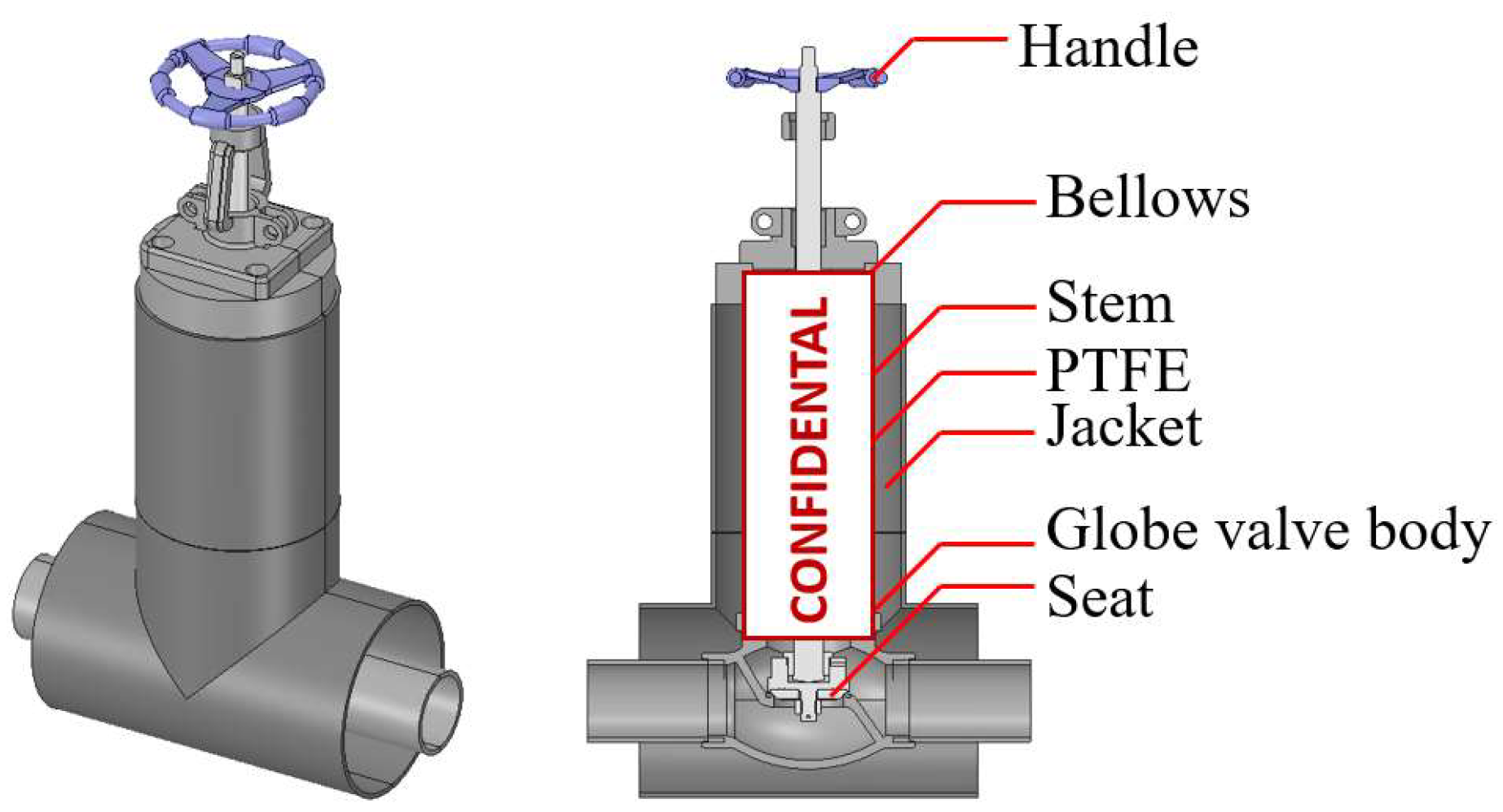
Figure 1. Feature of vacuum-jacketed globe valve.
Energies 17 02341 g001
Figure 2. Grid models for analysis of vaporization: (a) vacuum-jacketed pipe; and (b) vacuum-jacketed valve.
Energies 17 02341 g002
Figure 3. Distribution of velocity streamlines: (a) vacuum-jacketed pipe; and (b) vacuum-jacketed valve.
Energies 17 02341 g003
Figure 4. Distribution of static pressures: (a) vacuum-jacketed pipe; and (b) vacuum-jacketed valve.
Energies 17 02341 g004
Figure 5. Distribution of mass transfer rates: (a) vacuum-jacketed pipe; and (b) vacuum-jacketed valve.
Energies 17 02341 g005
Figure 6. The properties of liquid hydrogen along the main flow from the inlet to outlet of the vacuum-jacketed valve: (a) total pressure; (b) dynamic pressure; (c) static pressure; and (d) saturation temperature.
Energies 17 02341 g006
Figure 7. Distribution of mass transfer rate for BOG in vacuum-jacketed valve regarding tank pressures: (a) 1 bar; (b) 1.5 bar; and (c) 2 bar.
Energies 17 02341 g007
Table 1. Material properties of each component.
Density
[kg/m3]
Thermal Conductivity
[W/mK]
Specific Heat Capacity
[J/kgK]
SUS 316L790016470
PTFE21750.241000
EPDM8600.152010
Table 2. Load and boundary conditions for vaporization analysis.
Boundary ConditionValue
Working fluidLiquid and gaseous hydrogen
Inlet total pressure [bar]1, 1.5, 2
Outlet static pressure [bar]0
Operating pressure [bar]1
Turbulence modelk-ω SST
Thermal conductivity (vacuum 10−3 Torr) [W/mK]0.0014
Heat transfer coefficient [W/m2K]10
Ambient temperature [K]300
Table 3. BOG generation per hour in vacuum-jacketed valve regarding tank pressures.
Tank Pressures [bar]BOG Generation per Hour [m3/h]
10.132
1.50.221
20.283
Disclaimer/Publisher’s Note: The statements, opinions and data contained in all publications are solely those of the individual author(s) and contributor(s) and not of MDPI and/or the editor(s). MDPI and/or the editor(s) disclaim responsibility for any injury to people or property resulting from any ideas, methods, instructions or products referred to in the content.