Abstract
Based on the single-screw compressor (SSC) structure, a new type of composite slide valve (CSV) has been proposed and designed, featuring internal volume ratios of 2.8, 3.9, and 5.6 and operating under a partial load of 35%. The theoretical model describing the dynamic features and thermodynamic performance of the SSC with CSV has also been built. The pressure ratio of the experimental system can be adjusted from 3.3 to 7.8, and the experimental results demonstrate the CSV’s effective performance. The deviations between the calculated and measured results for volume ratio and input power are 3.33–9.08% and 0.32–8.03%, and the deviations for heating capacity and adiabatic efficiency range from 0.92–8.73% to 2.09–9.67%, respectively. The introduction of the CSV offers a novel approach to enhancing SSC efficiency. Both the theoretical and experimental findings lay a foundation for future optimization and design improvements in variable load and internal volumetric ratio single-screw compressors.
1. Introduction
As humanity progresses, the demand for energy in human society continues to increase, and countries around the world are also committed to the research, development, and utilization of clean energy [1,2]. The air source heat pump (ASHP), which has been extensively used in many fields, such as industrial, commercial, and residential heating, is a type of energy-saving air conditioning device. However, poor performance at low environmental temperatures and the drastic change in working conditions caused by the changes in ambient temperature have become a primary limitation for further application in cold regions [3,4]. The compressor serves as the powerhouse for the ASHP, with the crucial concern being whether the compressor’s design can satisfy the operational demands of the ASHP. Consider the conventional ASHP system that utilizes R22 refrigerant; the compressor’s pressure ratio is subject to fluctuations within a 4 to 12 range. Given the direct correlation between the pressure ratio and the inherent volume ratio, designing the latter at a fixed value may result in energy inefficiencies when the actual pressure ratio falls below or exceeds the optimum range. Such discrepancies can lead to a decline in the ASHP’s overall performance.
At present, the single-screw compressor (SSC), initially developed by Zimmern and Patel in the 1960s [5], has established itself as a pivotal technology across multiple domains, including heat pump systems [6], natural gas liquefaction [7], refrigeration industries [8,9], and the field of air compression, owing to its numerous distinct advantages, including a well-balanced stress distribution, uncomplicated design, minimal vibration, extended bearing life, and reduced noise levels [10,11]. Gate rotors can be manufactured from various materials [12]. In recent years, significant progress has been made in the research of composite materials [13]. The introduction of these materials, such as for the fabrication of gate rotors and piston actuators, can improve the SSC by reducing weight, minimizing friction, and enhancing durability, thereby boosting overall compressor performance. Typically, SSCs are engineered to meet the peak heating capacity demands of the ASHP. However, operating the SSC under varying partial load conditions, triggered by changes in environmental factors, can lead to energy inefficiency. Therefore, it is crucial to regulate both the heating capacity and pressure ratio of the SSC to adapt to diverse operational conditions, thereby enhancing its efficiency. The prevalent methods for optimizing SSC performance include frequency conversion regulation and slide valve control, with the latter being the most commonly implemented in SSCs [14]. The ability of the SSC to adjust its capacity and pressure ratio is largely contingent on the design and management of the slide valve. Implementing an appropriate control mechanism that can fine-tune the heating capacity and pressure ratio of the SSC is essential. Such an advancement would significantly bolster the performance of SSCs and further refine the efficiency of ASHP systems.
The focus of pressure ratio control lies in utilizing the compressor’s internal volume ratio control mechanism to regulate its internal pressure ratio. The operational characteristics of compressors equipped with this volume ratio control device, particularly in their application within water source heat pump systems, have been extensively researched [15]. These studies indicate a significant enhancement in the performance of heat pump systems. However, for the ASHP, public reports on compressors with integrated volume ratio devices are sparse, and these compressors exhibit markedly different operating conditions when compared to those in water source heat pump systems. The single-slide valve control device was first proposed by Zimmern et al. in 1983 [16], and then the structures were improved in 2000 [17]. Following this, Zhou et al. investigated the capacity adjustment mechanisms of the slide valve and the performance of compressors utilizing this single-control slide valve device [18]. Wang et al. [19] presented a mathematical calculation method to study the capacity control mechanism of single-slide valve. Variable frequency technology can regulate compressor capacity by altering the compressor’s rotational speed. Guo et al. [20] studied the industrial application of variable frequency drives in hydrogen fuel cell air compressors. Masuda et al. [21] used a slide valve control system to adjust compressor capacity by changing the speed of a single-screw compressor. Single- and twin-screw compressors have similar structures, and traditional slide valve control systems are also widely used in twin-screw compressors and their systems. Feng et al. [22] proposed an energy-efficient optimization method to directly adjust the slide valve position of the high-temperature screw compressor in a cascade refrigeration system, achieving optimal intermediate temperature control on-site. Sun et al. [23] tested the thermodynamic performance of twin-screw refrigeration compressors using both slide valve and variable speed control systems. The application of slide valve control systems in screw compressors holds promising prospects.
Due to the constraints of the geometric construction, the built-in volumetric ratio of the compressor cannot be adjusted using the capacity-adjusting valve. The variable frequency drive can adjust the capacity but cannot control the built-in volume ratio. In order to achieve built-in volumetric ratio and capacity regulation simultaneously, Zhou et al. [24] designed a kind of fission valve used in SSC. However, its complex structure has prevented its practical application to date. Wu et al. [25] designed a compound slide valve structure, but it is only an ideal model and has not undergone experimental study. In 2007, a double-slide valve (DSV) control device that can achieve internal volume ratio and capacity control was proposed by VILTER [26]. Subsequently, Wang et al. [27] conducted a study on the operating processes of the DSV control mechanism. The study demonstrated its capability to minimize energy loss. However, the double-slide valve’s structure consumes a significant portion of the compressor’s space, and its driving system is complex. For the large-sized compressor, it may have advantages where space is not a concern. But, when the diameter of the screw decreases to a certain value (such as less than 147 mm), the DSV system will be difficult to apply in practice. In addition, the instability and the leakage of the compressor with the DSV may increase because of the higher number of parts compared with the single-slide valve. To enable future development in the application of the small- and medium-sized SSCs, a more effective structure needs to be designed to improve the performance of the ASHP.
In this study, a novel composite slide valve (CSV) control mechanism is proposed to adjust both the internal volumetric ratio and capacity of the SSC. The geometric analysis model of the CSV was established alongside a comprehensive theoretical model that accounts for both leakage and built-in compression. Furthermore, we explore the dynamic features and thermodynamic efficiency of systems using the CSV, specifically focusing on its impact on compressor and heat pump system performance. The results indicate that the CSV structure can effectively regulate the performance of the SSC, and the results can provide a useful reference for improving the performance of single-screw compressors for ASHPs.
2. Theoretical Calculation Model
2.1. Geometry of the CSV and Its Working Mechanism
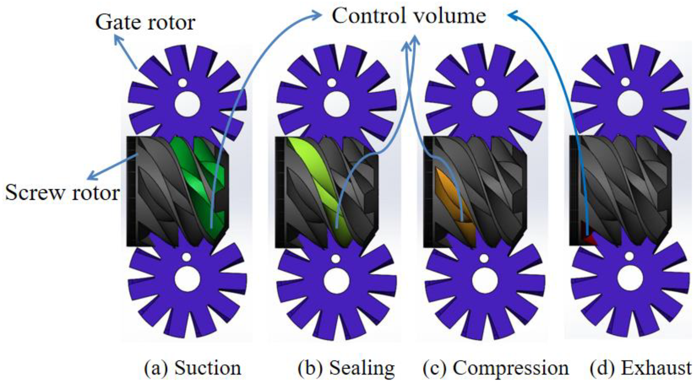
As shown in Figure 1, the primary structure of a single-screw compressor consists of a screw and two symmetrically arranged gate rotors. The control volume in Figure 1, which is the working chamber of the SSC, consists of six screw grooves. It forms a sealed compression chamber through the interaction of the screw, gate rotor, and external casing. As the screw and gate rotor rotate in tandem, the control volume gradually changes, enabling the four processes of suction, sealing, compression, and exhaust [28].
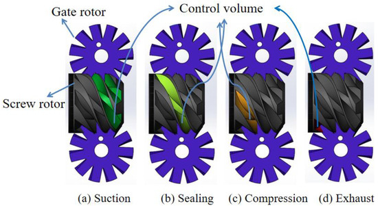
Figure 1.
The single-screw compressor structure and working principle.
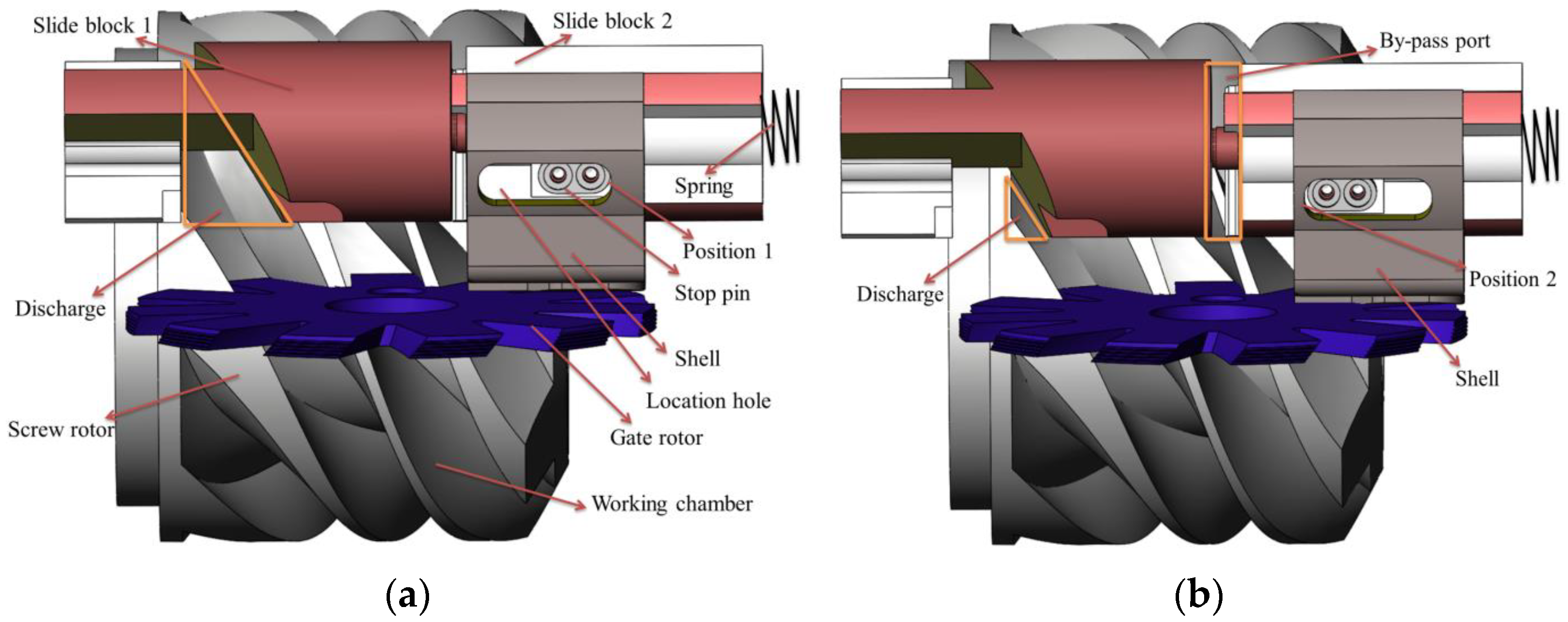
The CSV control structure designed by our team is illustrated in Figure 2. The CSV system has been ingeniously engineered to include two slide blocks (slide block 1 and slide block 2) to facilitate adjustable capacity and built-in volume ratio control using a singular slide valve. Slide block 2 is equipped with a stop pin on its surface, which can be anchored into a corresponding location hole in the shell to set its moving distance. When slide block 2 is secured at position 1, slide block 1 is mechanically coupled with it by a device such as the illustrated spring in Figure 2a, functioning as an internal volumetric ratio control slide valve. Here, the two blocks operate in unison as a single entity, propelled axially by a driving device. This arrangement seals off any bypass port, situating the SSC in a full-load condition with maximum discharge area and the internal volumetric ratio at its minimum.
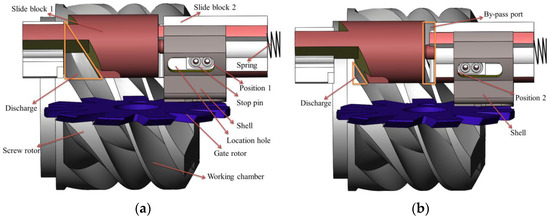
Figure 2.
Working mechanism of the CSV. (a) Full-load condition; (b) Part-load condition.
Conversely, Figure 2b depicts slide block 2 stationed at position 2 within the shell, where the CSV operates as a capacity control slide valve. In this mode, slide block 1 and slide block 2 decouple, allowing only slide block 1 to traverse axially via the driving device. Meanwhile, slide block 2 remains static at the preset location of position 2. Consequently, the gas from the working chamber is redirected back to the low-pressure side through the now-accessible bypass port created between the two blocks. This setup reduces the compressor’s operational load, with the discharge area attaining the designed minimum. The design of this structure is of great significance for the application and development of medium- and small-sized SSCs.
2.2. Working Process Model of the CSV
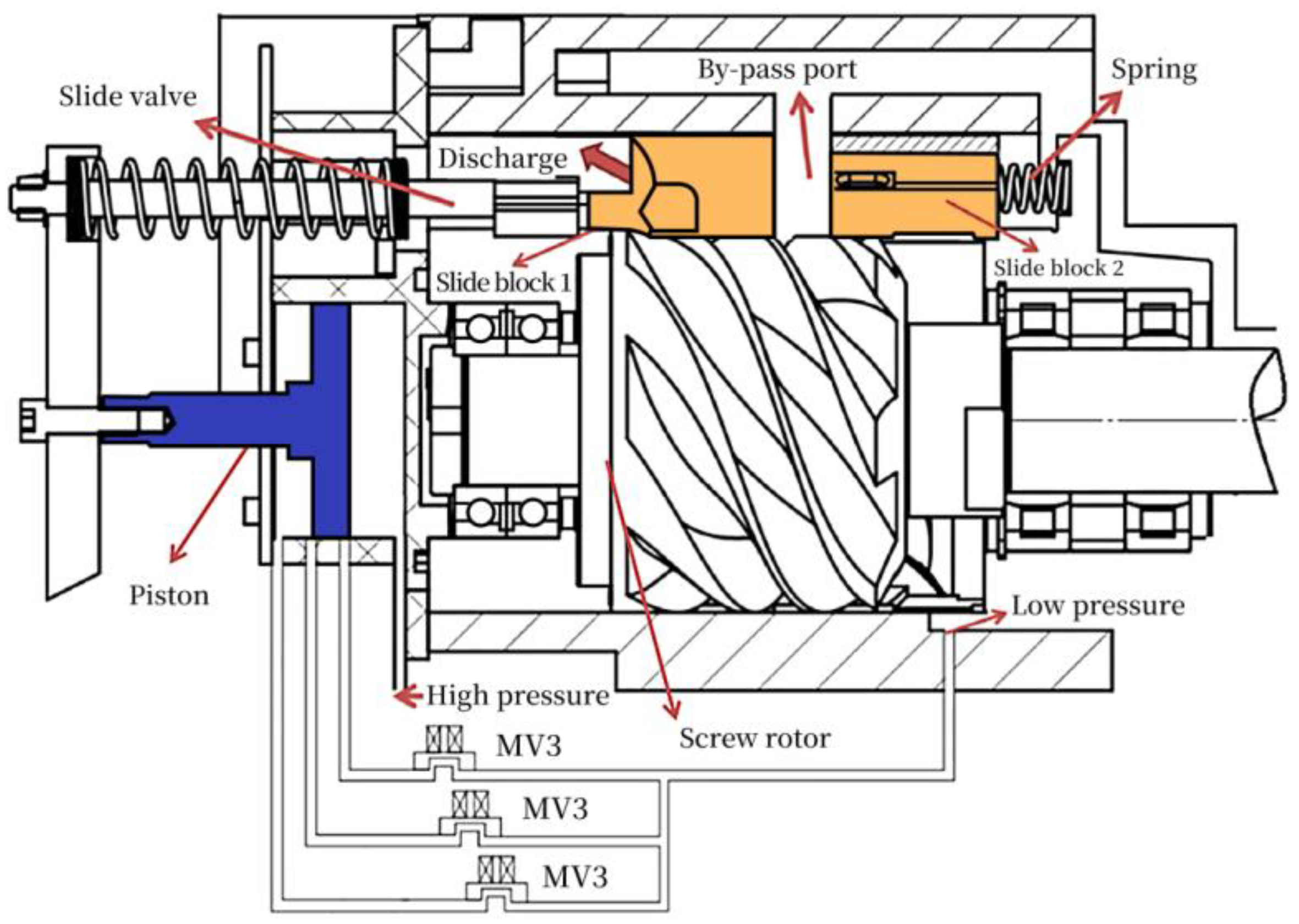
As shown in Figure 3, we employ three solenoid valves integrated into the compressor’s shell to manipulate the CSV. These valves are orchestrated by a Programmable Logic Controller (PLC), which sends switching signals to direct the CSV to the required position via piston movement, thereby modulating both the compressor’s load and internal volumetric ratio. Slide block 2 is actuated by a spring attached to the shell. The solenoid valves, labeled MV1, MV2, and MV3, connect to distinct ports in the piston. The movement of the piston is a result of the interplay between the working fluid’s differential pressure and the spring force connected to the piston. When all the magnetic valves are closed, the pressure at both ends of the piston will tend to balance due to leakage.
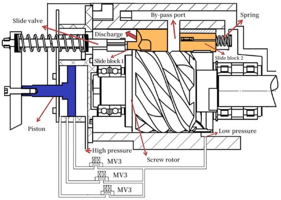
Figure 3.
The structure of the CSV control mechanism.
Owing to the differential pressure at both ends of the CSV, it will move toward the low-pressure end, and the discharge area reaches the maximum. At this point, the SSC operates at full-load condition, and the internal volumetric ratio of the SSC is 2.8. When MV3 is opened, the gas in the piston flows into the low-pressure end through MV3, causing the piston to move toward the high-pressure end, thereby driving the CSV because the piston’s force area is larger than that of the CSV. In this state, the SSC remains at full-load condition, and the internal volume ratio increases to 3.9. Similarly, when MV3 is closed and MV2 is opened, the piston shifts to the location where the port is connected to MV2, causing the CSV to move further toward the high-pressure end. The compressor maintains full-load condition with an internal volumetric ratio of 5.6. When MV3 and MV2 are closed and MV1 is opened, the piston moves to the port connected to MV1. At this juncture, the bypass port between slide block 1 and block 2 opens, and the compressor operates at 35% part load. The operating conditions for the CSV are delineated in Table 1, which shows that the SSC equipped with the CSV can be extensively employed in refrigeration and heat pump applications. The adoption of the CSV design provides a viable technical solution for optimizing SSC performance in the air conditioning sector.

Table 1.
Designed application conditions of the CSV.
2.3. Geometric Model of the CSV
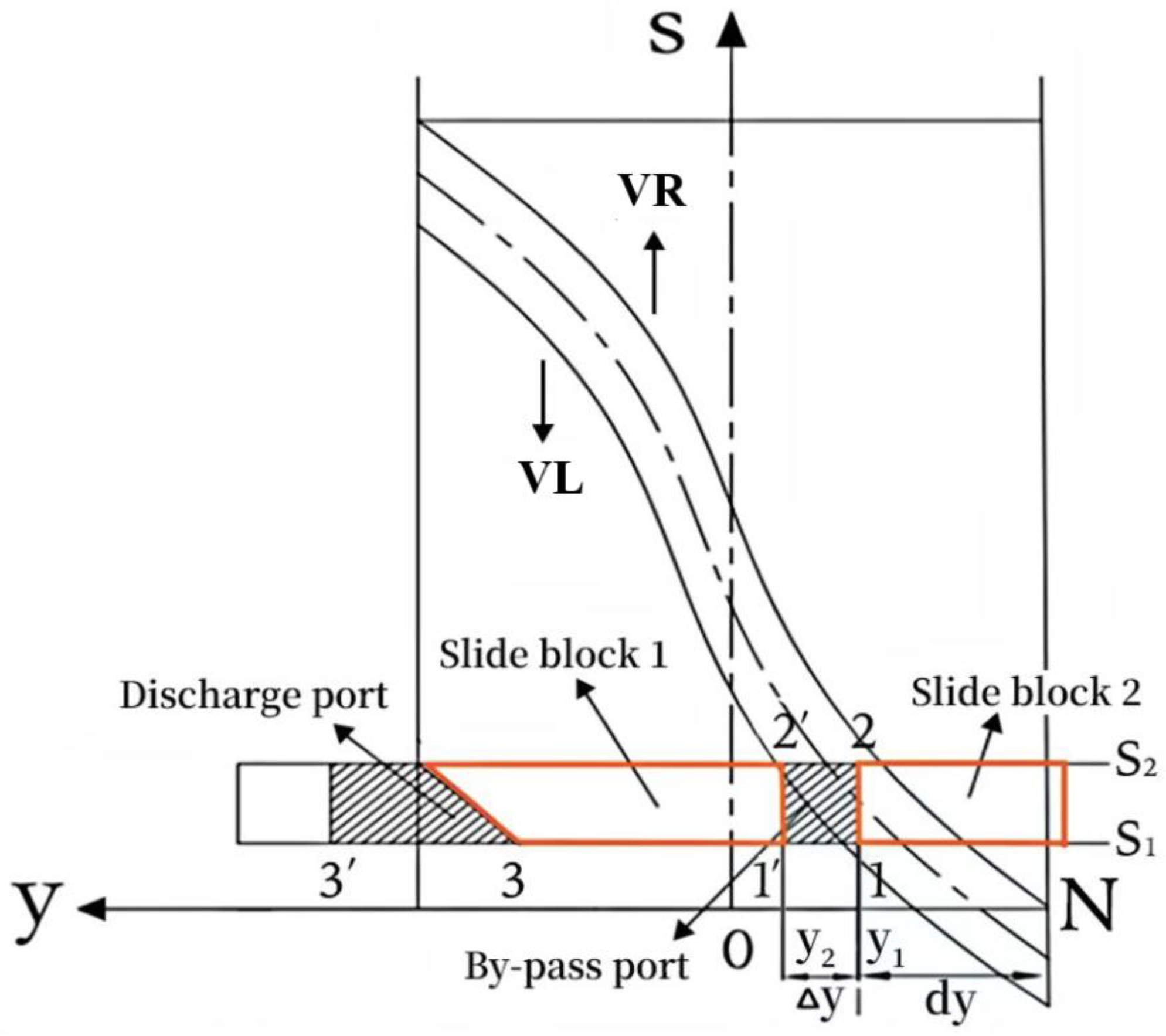
In order to study the operation characters of the SSC with the CSV, We need to establish a comprehensive geometric model of the CSV control structure. In the CSV system, the compressor operates under part load when the bypass port is opened. As shown in Figure 2, the bypass port is formed by the shell, slide block 1, and slide block 2. The area of the discharge port, which is formed by slide block 1 and shell, will be changed due to the movement of the CSV. In order to facilitate geometric analysis, the calculation model of one groove of the screw rotor shown in Figure 4 was established.
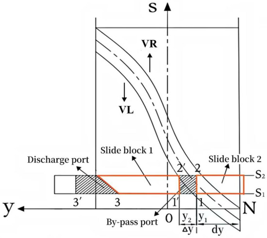
Figure 4.
Geometrical model of the CSV.
The curves VL and VR represent the left helical groove and the right helical groove, respectively. Point N, which is on the groove profile, is the start location where the refrigerant in the compression chamber begins to be compressed. When the CSV is located in different positions, the internal volumetric ratio and capacity will be changed. In Figure 4, Δy represents the axial distance between slide blocks 1 and 2, while dy denotes the axial distance from point 1 to point N. When the SSC runs under part-load condition and the VL crosses point 2, the bypass port will be opened to control the capacity. Then, the refrigerant in the compression chamber will flow back to the suction tube. The back flow will stop until the VR crosses point 1′. At this point, the bypass port is closed. When the curve of VL crosses point 3, the discharge port will open until the discharge process is over. As shown in Figure 4, when slide block 1 and slide block 2 are tightly fitted together, the compressor operates at 100% capacity. In this configuration, the CSV serves as a volume ratio adjustment slide valve, with the volume ratio value determined by the y-axis coordinate of point 3. This value is related to the length of slide block 1. The volume ratio range designed in this study is from 1 to 8.2. When slide block 1 and slide block 2 are separated, the bypass port opens, and the CSV functions as a capacity adjustment slide valve. The minimum capacity is determined by the y-axis coordinate of point 1’ in Figure 4, with the minimum capacity designed to be 25%. The actual operating load, as shown in Table 1, needs to be determined in conjunction with piston adjustment.
In order to obtain the effective discharge and bypass area, the equation of profile VL, VR, and the boundary curves surrounding the bypass port should be set up. The equation of VL can be obtained according to the literature [19]:
The equation of VR is as follows [19]:
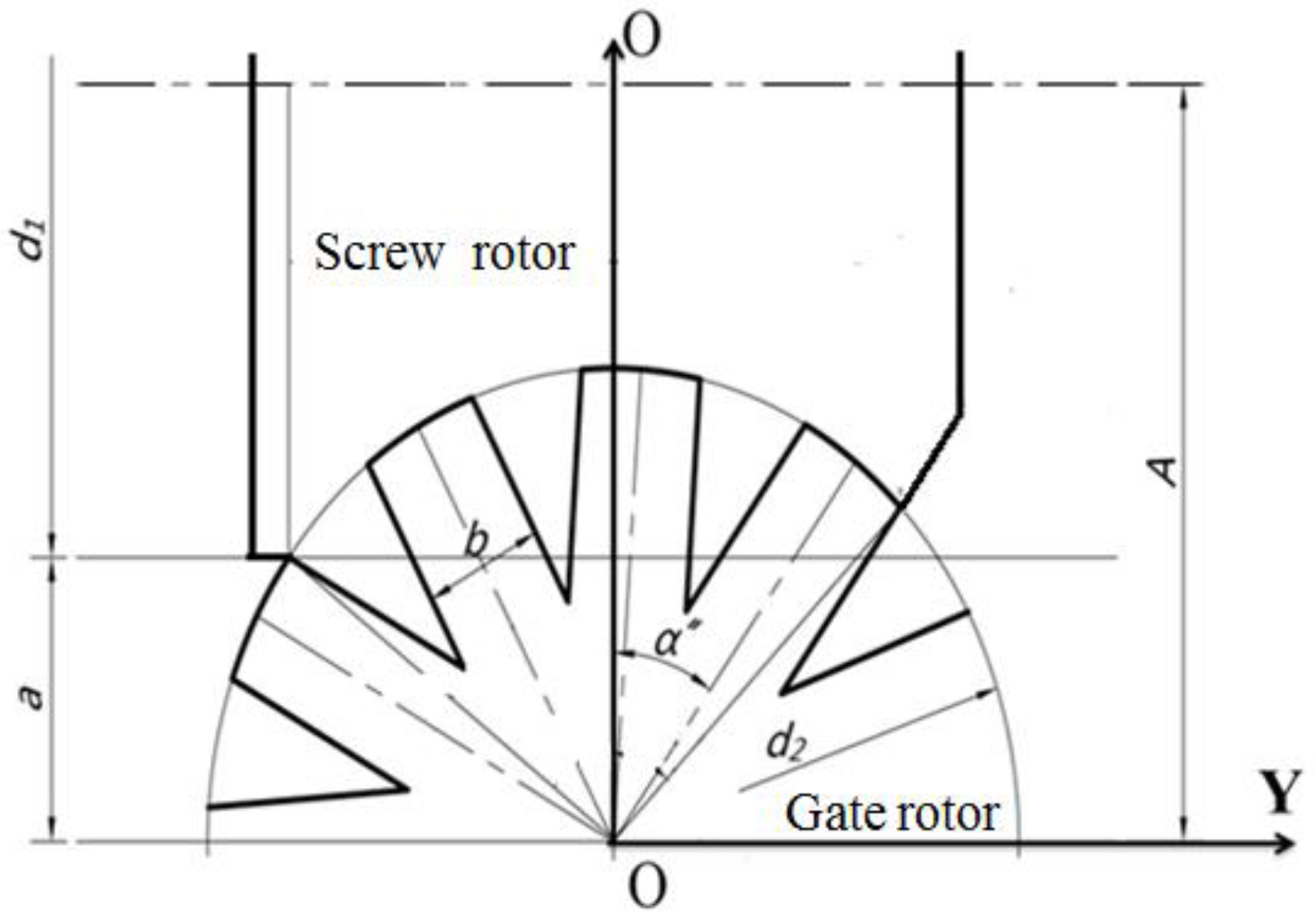
where (yw1, Sw1) stands for the coordinate point of the curve VL, and (yw2, Sw2) stands for the coordinate point of the curve VR. As shown in Figure 5, a is the distance between the screw rotor and gate rotor, b is the tooth width of the gate rotor, θ is the gate rotor angle, i12 is the transmission ratio, which is 11/6, α″ is the closed angle of the working chamber, and d1 and d2 are the diameter of the screw and gate rotor, respectively.
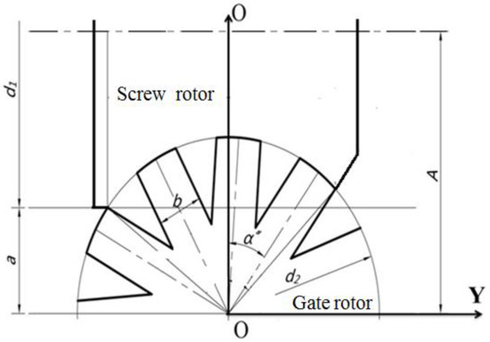
Figure 5.
The basic geometry of the meshing pair.
The formulation for the boundary curves of the bypass port is as follows:
where l is the distance of the axial motion of slide block 2, S0 is the distance of the radial spread of the CSV, which is 17.77 mm, and β is the radian of the CSV.
The intersection point coordinate of profile VL and the boundary equations of the bypass port are as follows:
The intersection point coordinate of profile VR and the boundary equations of the bypass port are as follows:
As shown in Figure 4, the profiles VL and VR will sequentially intersect with the bypass port’s boundary points. The critical angles are determined at the point where profiles VL and VR intersect with the bypass port’s boundary points. These angles are presented in Table 2 and represent the gate rotor angles. Figure 4 illustrates that the effective bypass port constitutes a closed area, delineated by both the groove profile and the bypass port’s boundary curves. Therefore, the calculation of the effective bypass area can be efficiently executed using Green’s theorem.

Table 2.
The geometric angles.
The anomalistic area formed by the curve VL and the bypass port can be calculated by the following equations:
Similarly, the anomalistic area formed by the curve VR and the bypass port can be obtained as follows:
In the equations, θ1bn = min(θ1b, θ1c), θ1cm = max(θ1b, θ1c), θ2bn = min(θ2b, θ2c), and θ2cm = max(θ2b, θ2c). Leveraging the geometric attributes of the CSV, the effective bypass area A(θ2, Δy) for varying gate rotor angles is derived by computing the difference between AL and AR.
The area A(θ2, Δy) can be expressed by the following equations:
Obviously, the internal volumetric ratio and the efficiency of the discharge process are influenced by both the size of the discharge area and the discharge port position. The calculation method for the discharge area is the same as the method for the bypass area.
The discharge area Ad(θ2, Δy) can be obtained by the following equations:
where the area AdL(θ, Δy) is bounded by VL and the discharge port, and the area AdR(θ, Δy) is bounded by VR and the discharge port.
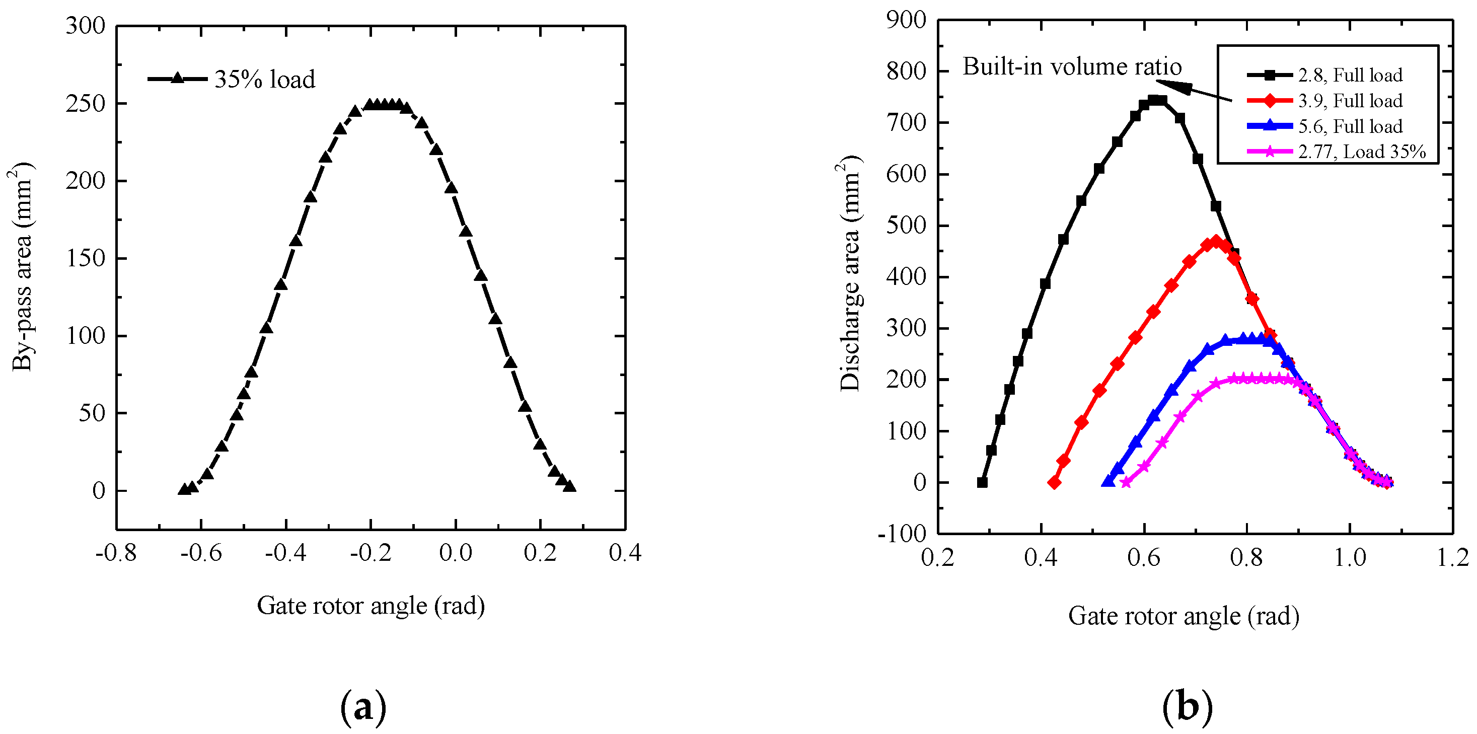
According to the equations above, the flow areas of the bypass and discharge ports under 35% load and variable internal volumetric ratios are depicted in Figure 6. Figure 6a shows that the bypass areas first increase and then decrease until the bypass port closes, at which point the working fluids start to be compressed. Figure 6b illustrates how the discharge areas are highly sensitive to the internal volumetric ratio. Under full-load operating conditions, the discharge area is inversely proportional to the internal volumetric ratio. For the testing SSC, the area of the discharge port reaches its smallest value under partial loading (35% load).
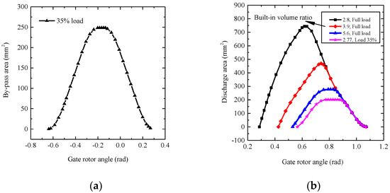
Figure 6.
The flow areas of the CSV change with the gate rotor angle. (a) Bypass area; (b) Discharge area.
2.4. Theoretical Equations
The working process of the compressor is influenced by many factors, including geometric structure, leakage, friction, heat transfer, and operating conditions. For convenience of analysis, this paper establishes the following reasonable simplified conditions:
- Within the working chamber, the temperature and pressure of the working fluid maintain uniformity, whereas the state parameters of the refrigerant gas undergo periodic changes;
- Within the defined control volume, the gas–oil mixture exhibits uniform properties, with the lubricating oil treated as an incompressible fluid;
- During the discharge process, the pressure loss can be neglected, and the impact exerted by the refrigerants’ body forces is also negligible.
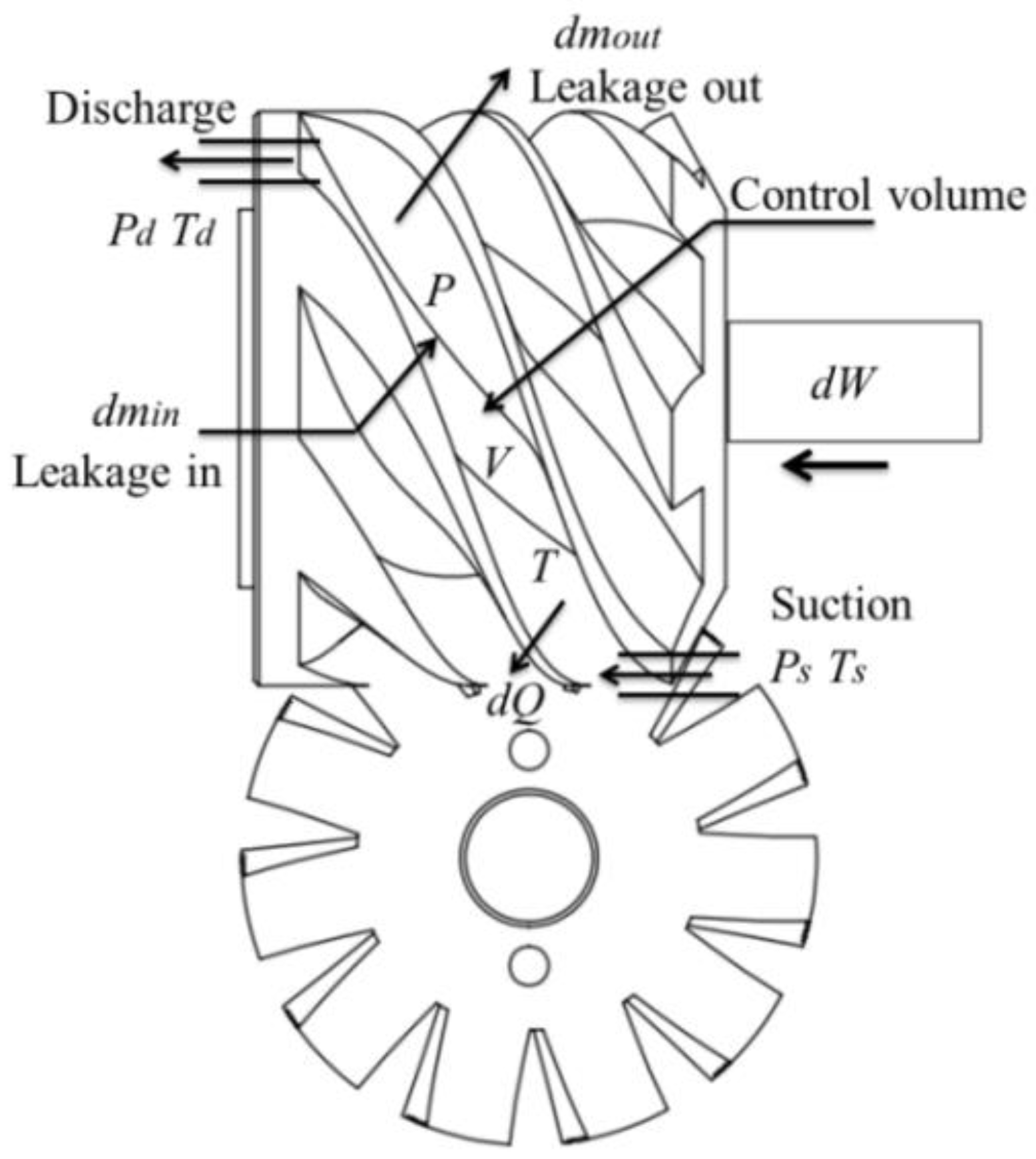
As shown in Figure 7, a single-screw groove is chosen as the control volume to streamline the analysis process. Based on the mass balance equation, the mass change equation of refrigerants is as follows:
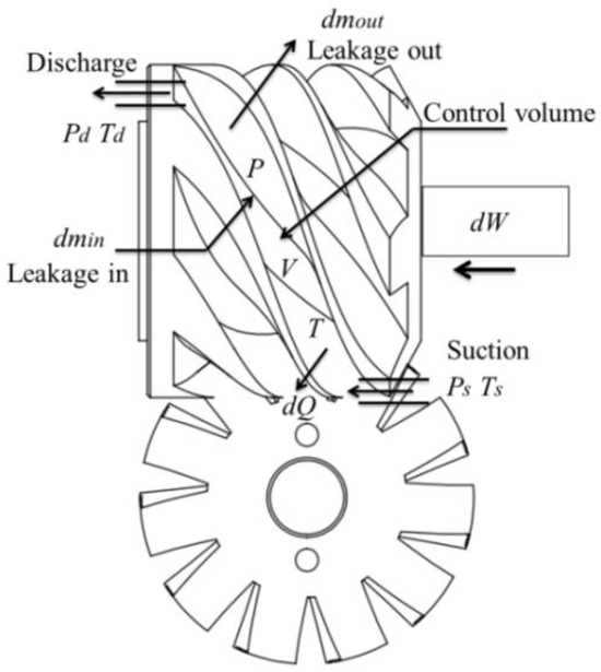
Figure 7.
The control volume.
For the control volume, the energy conservation equation is obtained as follows:
Assuming the potential and kinetic energies are negligible, the following equation is found:
where ṁ denotes the mass flow rate within the control volume, θ1 represents the rotation angle of the screw, ṁi signifies the combined suction and inflow rate of leakage for the working fluid, ṁo encapsulates both the discharge and outflow rate of leakage for the working medium, dQ represents the heat transfer capacity, dW is the compression work, and u and h, respectively, denote the internal energy and enthalpy of the working medium.
Drawing on fundamental thermodynamic principles, the state variables of the working mediums, such as temperature, pressure, and specific volume, are delineated as per the guidelines in reference [29]:
where P denotes the pressure within the volumetric element, Vc is identified as the maximum volume of a single groove, T represents the temperature of the volumetric element, v stands for the specific volume, and V refers to the volume of the element.
2.5. Leakage Model
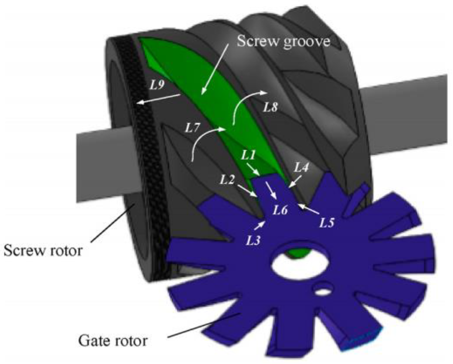
Figure 8 shows that there are nine leakage paths in SSC. Further details on the geometric relationships of these nine leakage paths are elaborated in our prior research [30] on a single-screw expander, revealing that they share identical leakage paths. In the SSC, lubricating oil is pivotal to the compressor’s performance efficiency. Therefore, it is essential to model the working fluid’s flow as a biphasic gas–oil mixture.
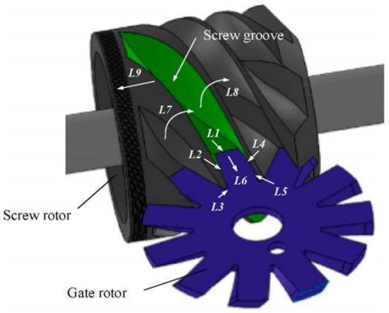
Figure 8.
Leakage paths of the SSC.
The leakage quality of the working is shown as follows:
The void fraction α and slip factor f is given by the following:
where Cl denotes the flow coefficient, established at 0.65 based on findings from references [31,32]. Sa denotes the leakage path area, vg represents the gas velocity, ρg is the gas density, ρl is the oil density, β represents the proportion of gas within the mixture, and hhp and hlp represent the enthalpy at the high-pressure and low-pressure ends, respectively, as they relate to the leakage paths. f is the slip factor.
2.6. Model for Calculating the Bypass and Discharge Flow Processes
Based on the geometric model of the CSV described in Section 2.1 and Section 2.2, the areas of the bypass and discharge ports were determined. Consequently, this enables the definition of the working fluid’s flow pattern through the discharge and bypass ports. Thus, the bypass and discharge processes can be considered as a form of leakage. The mass flow rate of the refrigerant gas through the bypass port can be calculated using the following equation:
where h(θ2) represents the enthalpy of the refrigeration gas in the compression chamber, hlow stands for enthalpy at the low-pressure end, and Cb is the flow coefficient [33].
2.7. Numerical Calculation
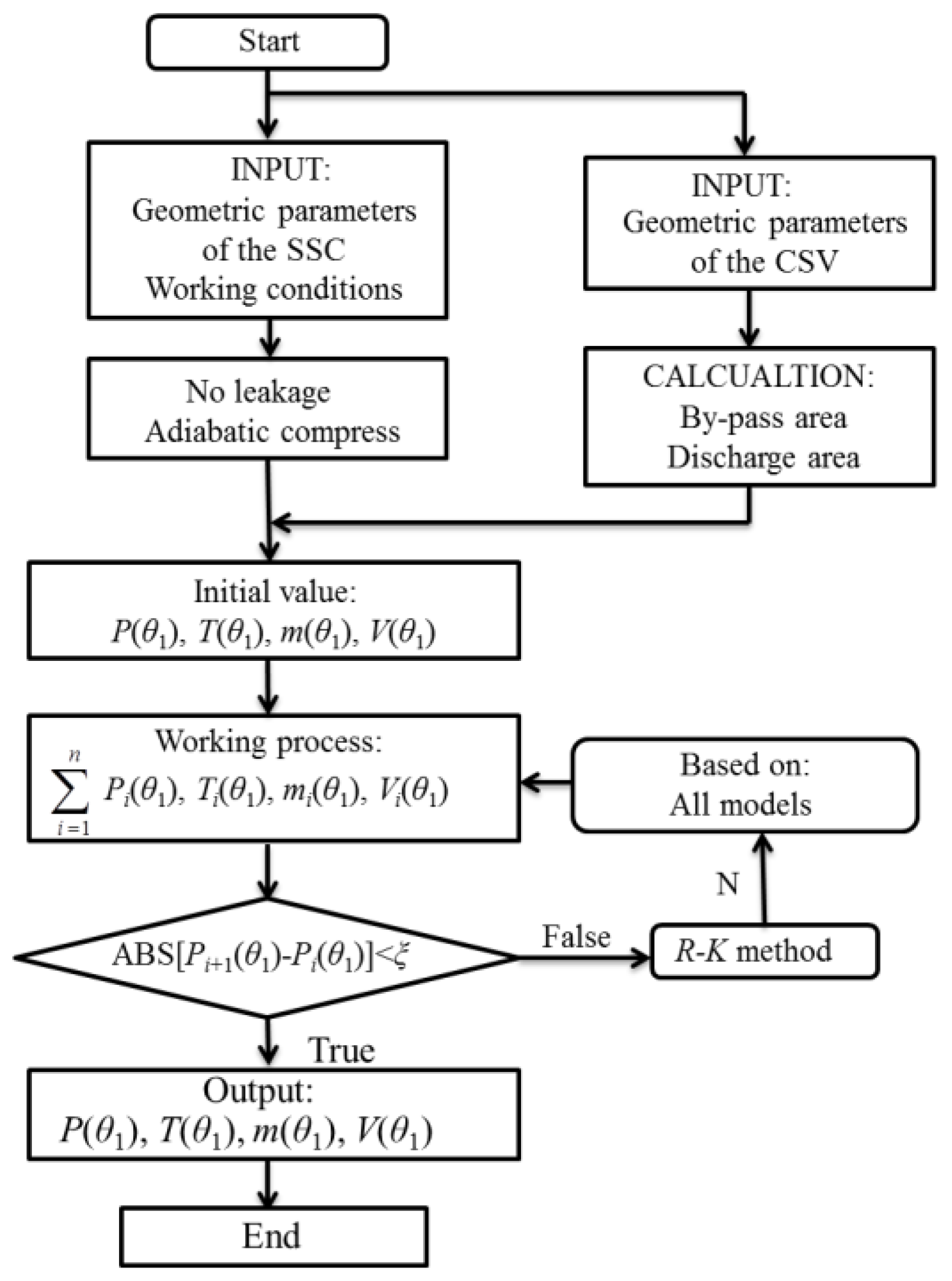
According to the theoretical equations mentioned above, a mathematical model that captures the thermodynamic operations of the SSC equipped with CSV was built. Figure 9 presents a flowchart illustrating the analysis process. Initially, the geometric parameters of the SSC with CSV, as detailed in Table 3, should be regarded as the foundational parameters. These parameters can then be initialized under the assumptions of no leakage and an adiabatic compression process. The Runge–Kutta method was applied to derive the numerical solutions for the equations and to ascertain the transient thermodynamic state variables of the operational cycle, such as m(θ1), T(θ1), and P(θ1). Once the absolute value of ξ, representing the pressure differential between successive calculations, satisfies the stipulated precision criteria, the necessary state variables of the working medium are achieved. The information relating to refrigeration can be obtained via the source code of the REFPROP program.
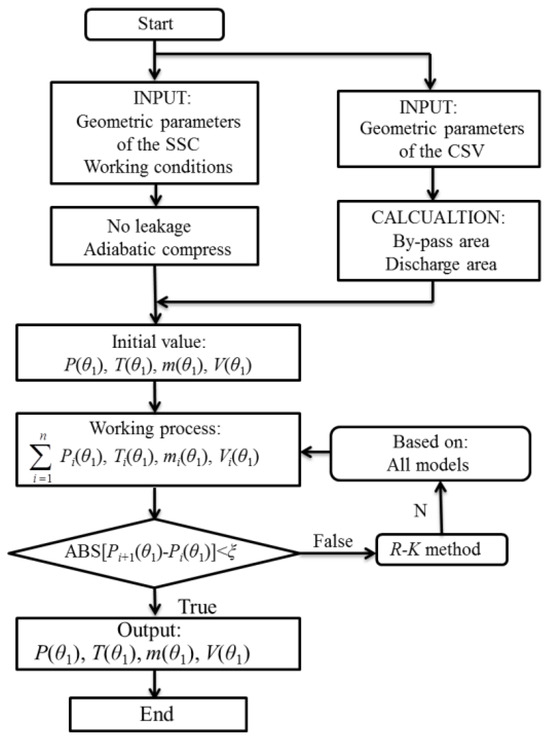
Figure 9.
Flow chart of analysis procedure.

Table 3.
Main structural and operational parameters.
3. Experimentation Research
3.1. Testing System
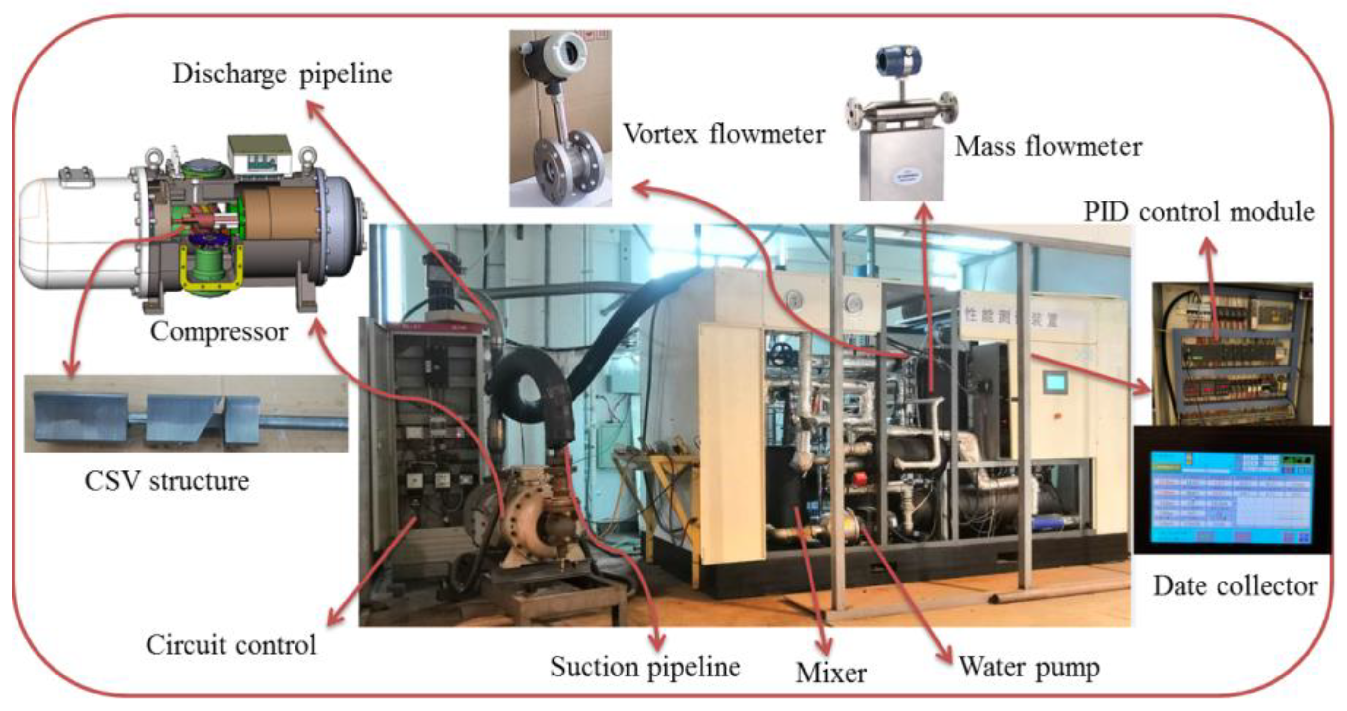
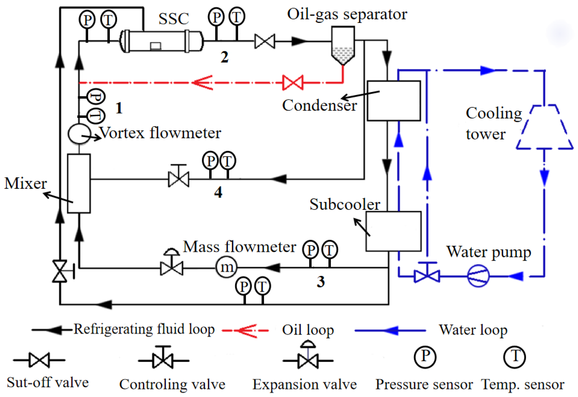
To validate the feasibility of the CSV and the accuracy of the mathematical model, a single-screw compressor equipped with the CSV system was meticulously designed and fabricated. Following the gas cooling loop method, the testing system was established, as depicted in Figure 10, with a schematic representation provided in Figure 11. The gas–oil mixture exiting the SSC is channeled into the gas–oil separator, where the lubricating oil is isolated and then recirculated back into the SSC. Subsequently, the gas exiting the gas–oil separator splits into two routes. The first route leads directly to the mixer, with its pressure finely adjusted via a pressure control valve to align with the compressor’s inlet parameters. The second route passes through the condenser and sub-cooler for cooling before being directed into the mixer, facilitated by a mass flow meter and an electronic expansion valve.
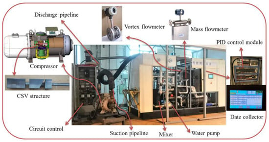
Figure 10.
The performance experimental system of the SSC.
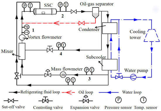
Figure 11.
The testing schematic diagram.
These two streams converge in the mixer to establish the compressor’s inlet conditions, ensuring the inlet gas is appropriately superheated. This process marks the completion of the entire cycle. The test working parameters, including temperature, pressure, and degree of superheat, can be automatically adjusted by the PID (Proportional, Integral, Derivative) control module. Moreover, the experimental setup incorporates both a water circuit and a liquid injection loop. The pressure and temperature are represented by the letters P and T, respectively, in Figure 11.
3.2. Experimental Device and Testing Method
In Figure 11, the mass flow meter, positioned downstream of the sub-cooler, is utilized to quantify the mass flow rate of the liquid working fluids. The gas flow rate entering the compressor is accurately measured using a vortex flow meter with a precision of ±1%. Pressure and temperature sensors are strategically positioned along the pipeline at locations 1, 2, 3, and 4. The power meter assesses the input power, and Table 4 details the measurement capabilities and accuracy of each utilized instrument.

Table 4.
Precision and measurement ranges of each instrument.
The principles of mass and energy conservation in the mixer are encapsulated by the following equations:
In the equations, ṁ1m represents the flow rate exiting the mixer, ṁ3m is the flow at the sub-cooler’s outlet, ṁ4m denotes gas flow in the mixer’s inlet pipe, h1m specifies the specific enthalpy at the mixer’s outlet, h3m specifies the specific enthalpy of the cooled liquid leaving the sub-cooler, and h4m indicates the specific enthalpy of the gas entering the mixer.
Based on the Equations (25) and (26), The volumetric flow rate at the inlet of the SSC can be determined as follows:
where ρ1 is the density of the mixer outlet, and h2m is the specific enthalpy of the compressor exhaust. It should be noted that the SSC’s inlet volumetric flow rate can also be gauged using a vortex flow meter. Therefore, to guarantee the precision of the experimental outcomes, the absolute disparity between the measured value V1c and the computed value V1m must remain within a specified margin (±5%).
The equation for calculating the cooling capacity is shown below:
In the equation, hf2 represents the specific enthalpy of the liquid refrigerant at the saturation temperature corresponding to the discharge pressure.
4. Results and Discussion
4.1. Thermodynamic Performance of Working Process
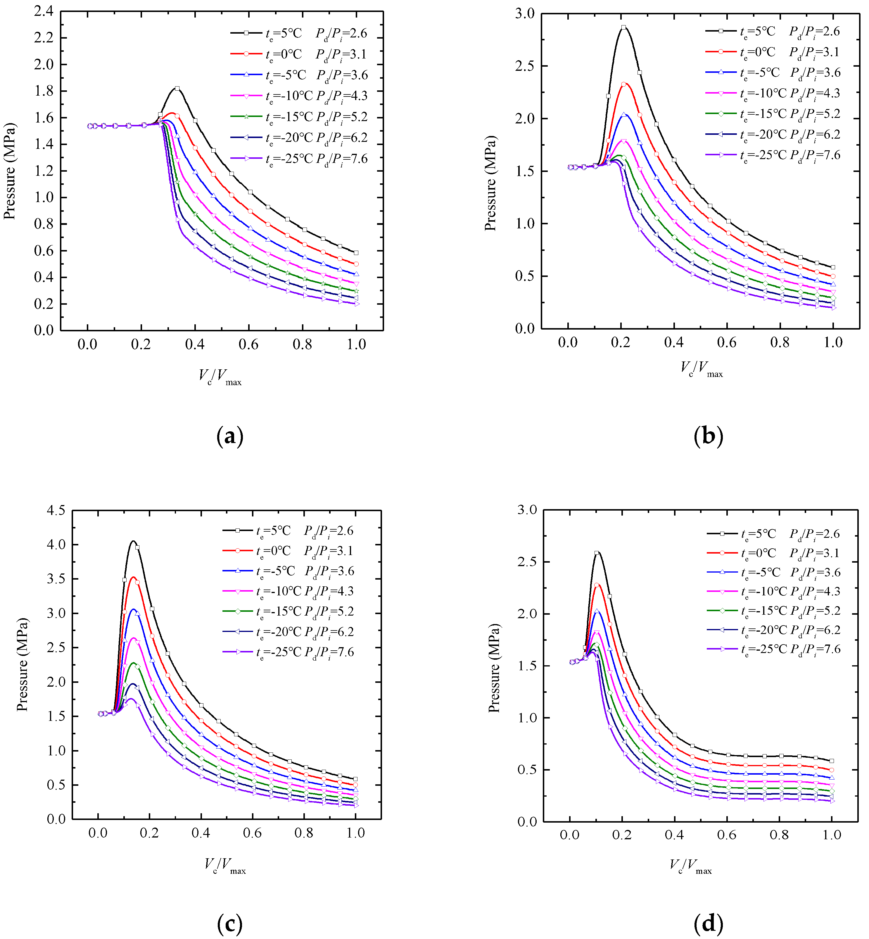
The operating performance of the SSC with CSV at different operating conditions is depicted in the P-V chart, which offers valuable insights for designing CSV systems. Based on the mathematical calculation models, the P-V charts of the SSC are illustrated in Figure 12. The variable te, ranging from −25 °C to 5 °C, represents the evaporating temperature, while the ratio Pd/Pi signifies the pressure ratio during operation, with Pi denoting the evaporating pressure and Pd the condensing pressure. The condensing temperature is established at 40 °C, accompanied by a superheat temperature of 10 °C.
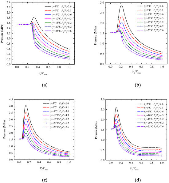
Figure 12.
Calculated values of P–V across varied pressure ratios and volume ratios. (a) Vi = 2.8, Pξ = 3.41; (b) Vi = 3.9, Pξ = 5.05; (c) Vi = 5.6, Pξ = 7.77; (d) Vi = 2.77, Pξ = 3.36.
Vc signifies the control volume of the compression chamber, whereas Vmax represents the maximum value of the control volume. Vi is the internal volume ratio of the SSC, and Pξ is the pressure ratio that corresponds to each value of the Vi. The importance of adjusting the internal volume ratio is evident from Figure 12. When the CSV serves as an internal volume ratio control slide valve, the internal volume ratio can be adjusted according to the demands of the actual working conditions. This adjustment guarantees a harmonization between the internal and external pressure ratios of the SSC.
Should the internal pressure ratio of the SSC, Pξ, which depends on Vi, exceed the external pressure ratio, pd/pi, as dictated by the condensing and evaporating pressures (e.g., for operating conditions like te = 5 °C in Figure 12a, −10 °C ≤ te≤ 5 °C in Figure 12b, and −25 °C ≤ te ≤ 5 °C in Figure 12c), then the gas within the compression chamber will experience over-compression. Consequently, the pressure in the control volume will exceed the discharge pressure when the discharge port opens. Given that the discharge port opens progressively, the gas pressure will initially rise for a period before subsequently decreasing, as illustrated in Figure 12. Should the internal pressure ratio fall below the external pressure ratio, as in scenarios where te varies from −25 °C to −10 °C (Figure 12a) and from −25 °C to −20 °C (Figure 12b), gas will retroflow into the operational chamber via the open discharge port until the pressures within the chamber and at the discharge align. Either over-compression or under-compression will lead to decreased compressor performance. Therefore, reasonable adjustment for the internal volume ratio at different working conditions can reduce energy consumption and improve efficiency.
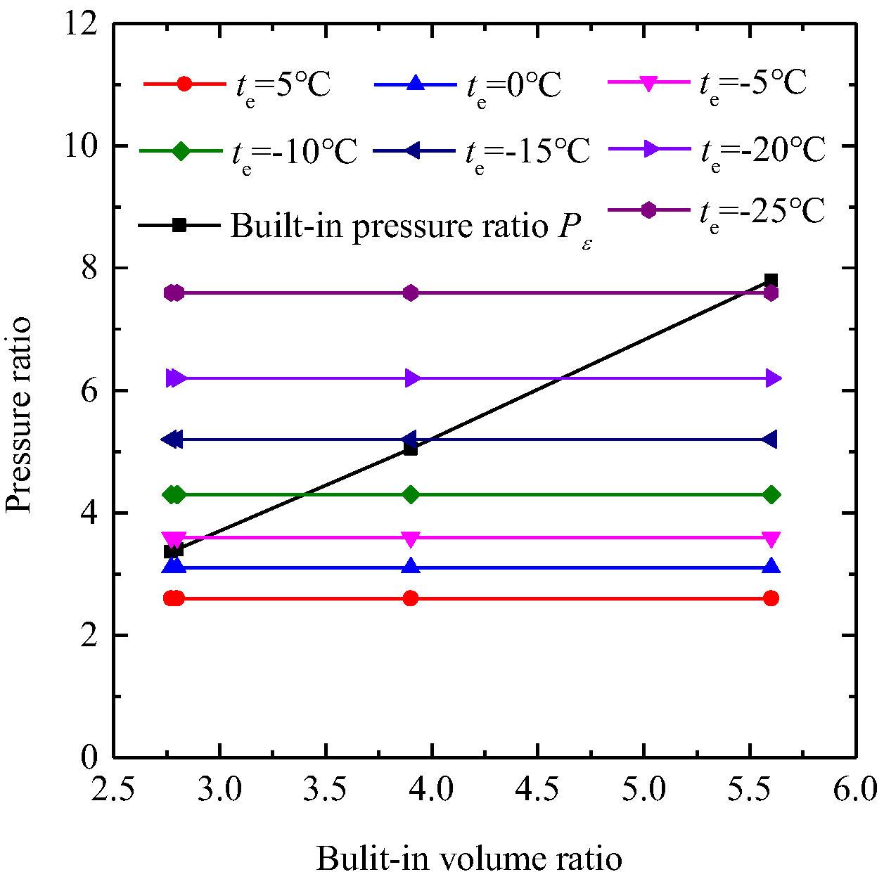
Figure 12d shows the operating conditions under a partial load of 35%. The pressure of the gas will slightly increase, remain unchanged for some time, and then rapidly increase. This pattern occurs because the gas in the compression chamber undergoes pre-compression as its volume decreases. When the compression chamber opens to the bypass port, the working medium flows back into the suction chamber through the bypass port. As the screw angle increases, the bypass port closes, and the gas continues to be compressed until the discharge port opens. Figure 13 presents the comparison between the internal pressure ratio, which depends on Vi, and the external pressure ratio, as dictated by ambient conditions. In an air source heat pump system, the evaporation temperature mainly depends on the ambient temperature. With the CSV structure, the pressure ratio can be adjusted from 3.3 to 7.8, covering most of the working conditions, including both refrigeration and heating. If there is a mismatch between the internal and external pressure ratios of the SSC, compression loss will occur.
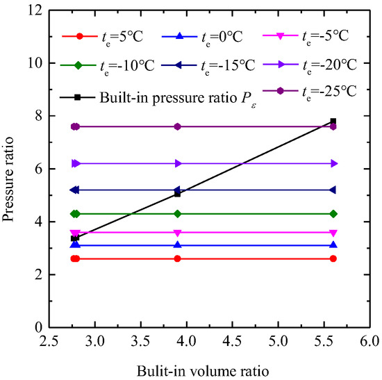
Figure 13.
Calculated results of internal and external pressure ratios.
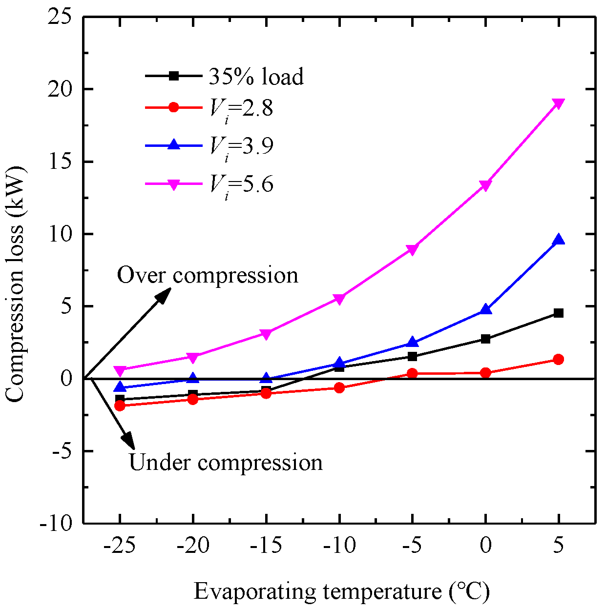
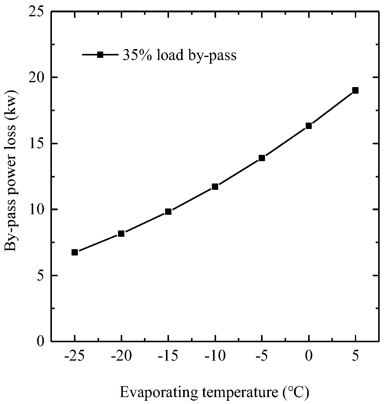
The calculated results of the compression loss are depicted in Figure 14, where negative values indicate a loss in compression power. The maximum over-compression loss can reach up to 19.1 kW, which accounts for approximately 31.5 percent of the input power when te is 5 °C and Vi is 5.6. We have found that the compression loss can be reduced to 1.33 kW through the adjustment of the CSV structure. When operating under partial load, the compressor’s bypass process also consumes energy, as depicted in Figure 15. The bypass power loss can vary from 19.01 kW to 6.74 kW. Moreover, the proportion of input power lost to bypass can range from 28.5% to 61.4% under the calculated conditions. So, it is necessary to optimize the CSV structure so as to reduce the bypass power loss in practical work.
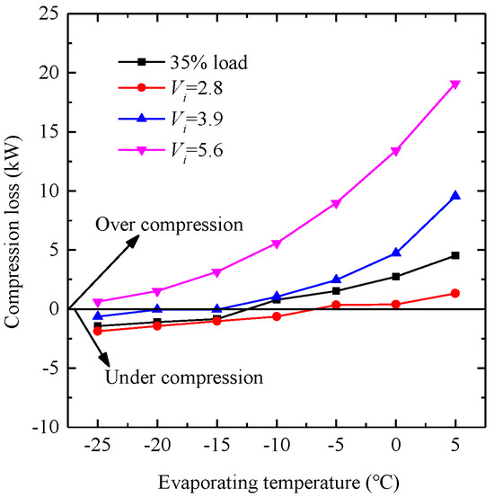
Figure 14.
Calculated results of the compression loss under different working conditions.
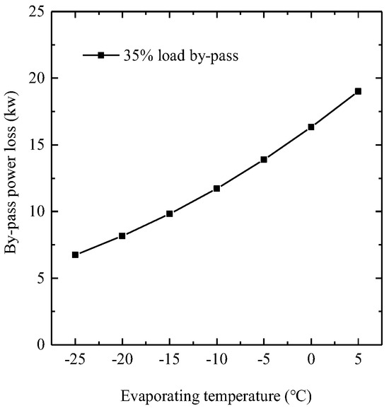
Figure 15.
Calculated results of the bypass process power loss.
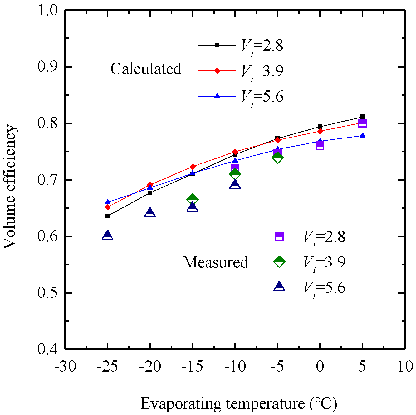
The calculated and measured parameter results under different working conditions of the SSC with CSV are shown in Figure 16, Figure 17, Figure 18, Figure 19 and Figure 20. For a range of built-in volume ratios, Figure 16 demonstrates that the volume efficiency decreases as the evaporating temperature decreases. The deviations between the measured and calculated values range from a minimum of 3.33% to a maximum of 8.98%. Under the same working conditions, the volume efficiency is related to the compression loss of the compressor, as shown in Figure 14. Taking te = 5 °C and te = −25 °C as examples, volume efficiency diminishes as Vi increases at te = 5 °C. In contrast, at te = −25 °C, volume efficiency rises with an increase in Vi. This phenomenon occurs because either over-compression or under-compression loss, which leads to increased leakage, adversely affects volume efficiency.
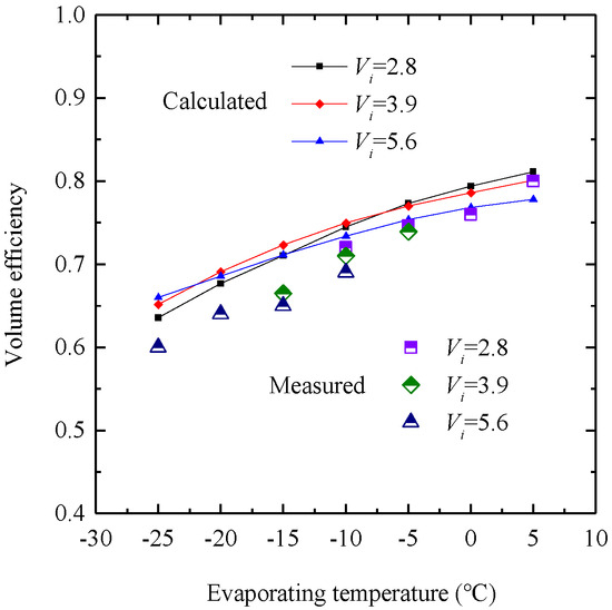
Figure 16.
Results of theoretical and experimental values.
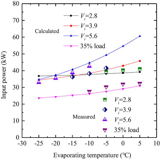
Figure 17.
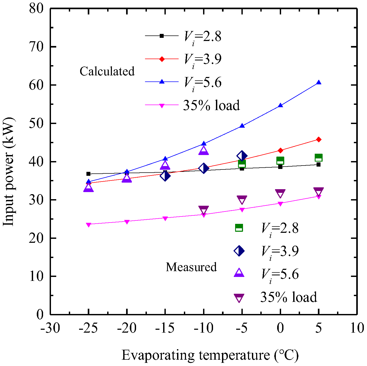
Measured and calculated data of input power.
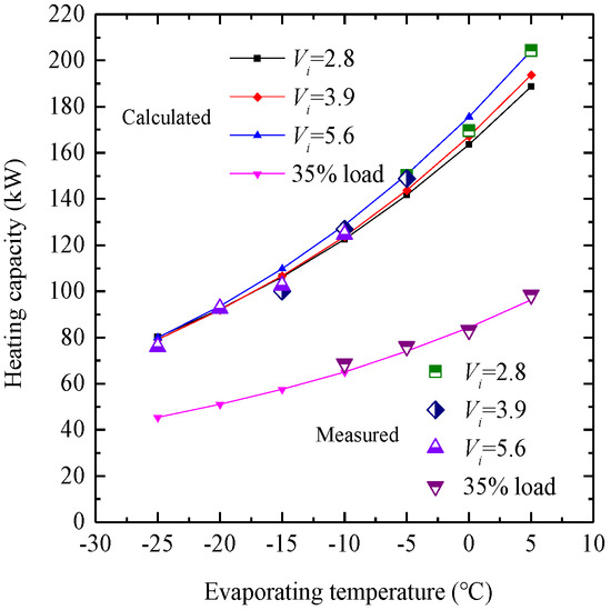
Figure 18.
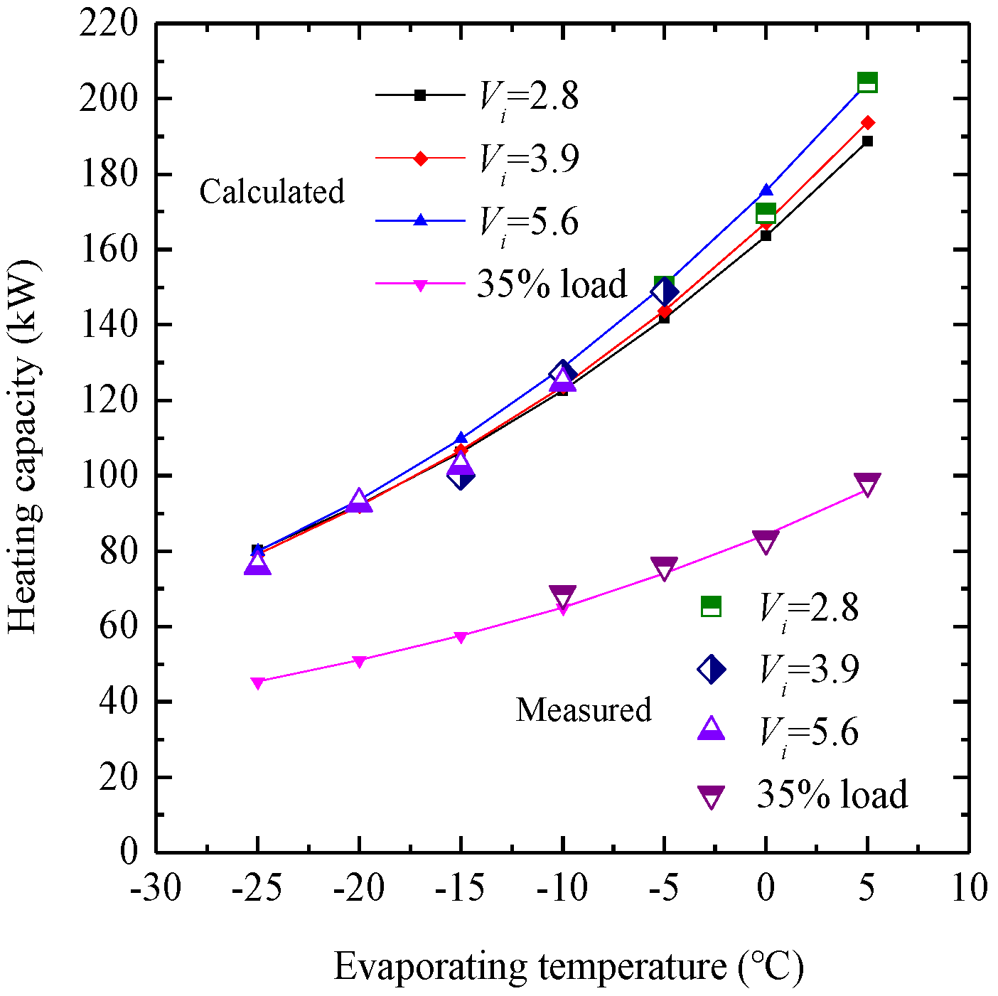
Measured and calculated data of heating capacity.
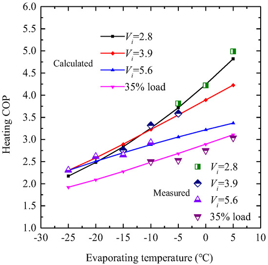
Figure 19.
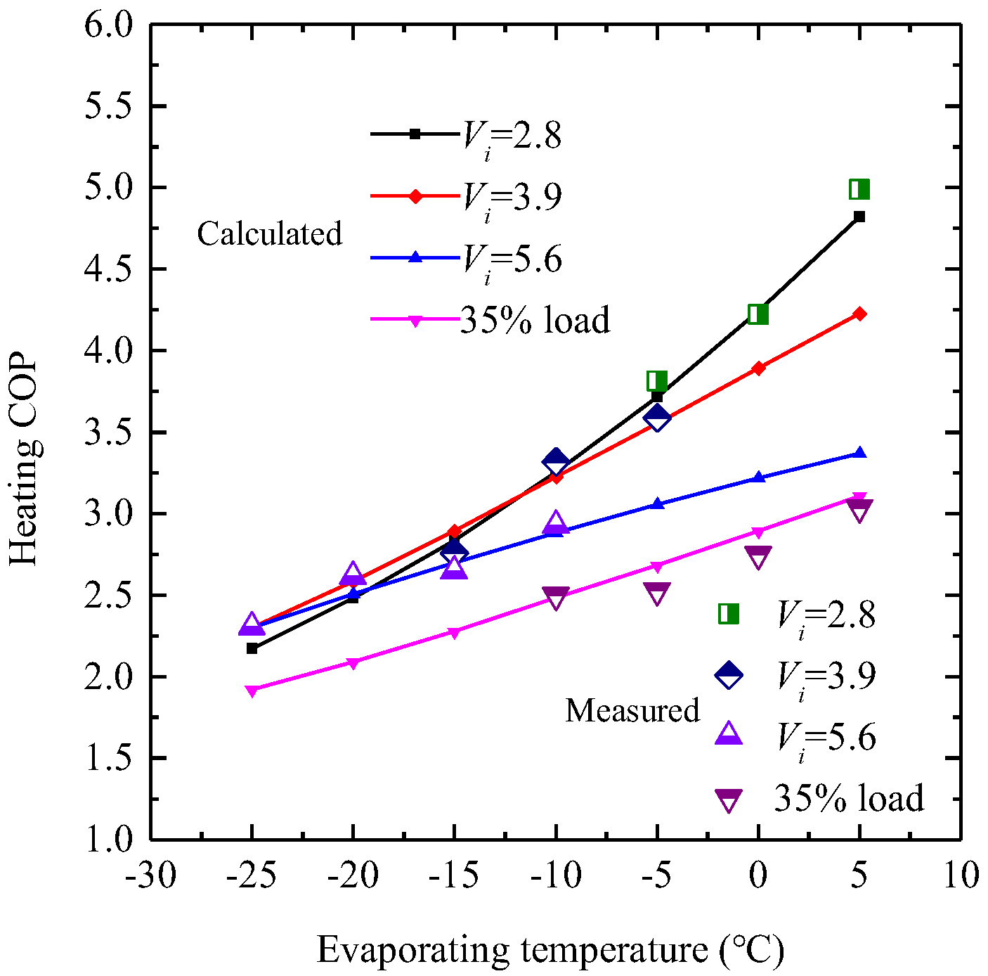
Measured and calculated results of heating COP.
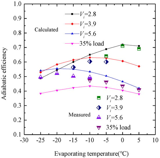
Figure 20.
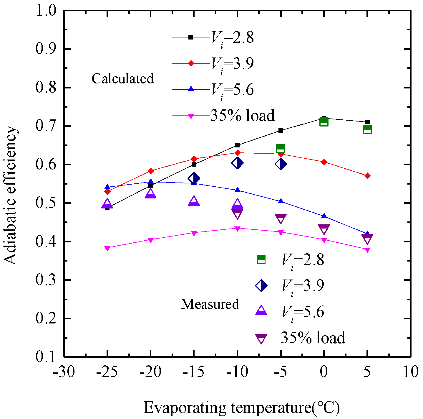
Measured and calculated data of adiabatic efficiency.
Figure 16 shows that the overall trend of measured volumetric efficiency is lower than the calculated value. This discrepancy is primarily attributed to leakage in the SSC, where greater leakage results in lower volumetric efficiency. As illustrated in Figure 8, there are nine main leakage paths in the compressor. Among them, leakage lines L7 and L8 are the primary pathways and reflect the complexity of the engagement profiles between the screw and gate rotor. In practice, the machining accuracy may not reach the designed level, leading to an actual leakage gap that is larger than the calculated value. This increase in leakage consequently results in the measured volumetric efficiency being lower than the calculated value.
The input power and heating capacity under various built-in volume ratios and partial loads are depicted in Figure 17 and Figure 18. The calculated results closely align with the measured data, indicating that the compressor’s input power under partial load is significantly lower than at full-load conditions because of the bypass process, with deviations of 4.46–8.93% and 0.32–5.35%, respectively. The experimental data show that the CSV can work efficiently. Figure 17 and Figure 18 illustrate that both the input power and heating capacity decrease with the evaporation temperature decrease. According to Figure 18, the heating capacity at partial load is notably lower than at full load, with deviations between the calculated and measured results ranging from 0.83% to 7.58%. The heating capacity is significantly reduced at low evaporating temperatures. Regarding different internal volume ratios, the heating capacity at Vi = 5.6 exceeds that at Vi = 2.8 when te = 5 °C due to over-compression increasing the input power, which in turn raises the heating capacity correspondingly.
According to Figure 13 and Figure 14, the differences between various internal volume ratios will diminish as compression loss decreases. As shown in Figure 19, the heating COP at partial load is lower than under full-load conditions. The deviations between the measured and calculated results range from a minimum of 0.92% to a maximum of 8.73%. Similarly, a mismatch between the internal and external pressure ratios of the SSC will lead to a notable decrease in the heating COP. Figure 20 illustrates the variations in adiabatic efficiency relative to the evaporating temperature, comparing calculated and measured results, with deviations ranging from 2.09% to 9.67%. During the test operations, the adiabatic efficiency initially increases and then decreases. The experimental results confirm the accuracy of the theoretical calculations.
It is also clear that energy losses during the compression process have a significant impact on the adiabatic efficiency. Thus, properly adjusting the internal volume ratio can effectively lower energy consumption and enhance the working parameters of the heat pump system. The alignment of measured and calculated outcomes affirms the reliability of the theoretical model that delineates the internal operational process of the SSC with CSV, proving it to be a dependable tool for predicting the compressor’s thermodynamic performance.
4.2. Uncertainty Analysis
Standard error analysis techniques were employed to assess the uncertainties associated with the theoretical findings. Systematic and random measuring errors are inevitable in the testing process. Within the testing framework, the key variables include pressure, temperature, power, and flow rate. The equation below captures the error propagation relationship:
More precisely, the target outcome is a stable function z(x1, x2, … xn) derived from the direct physical variables (x1, x2, … xn), each associated with uncertainties (δx1, δx2, … δxn). The overall relative precision of the experimental data is determined using the equation below:
Reflecting the precision of each measuring device as listed in Table 4, the aggregate relative accuracy for the heating capacity and the heating COP stand at 3.24% and 3.43%, respectively. Meanwhile, the adiabatic efficiency exhibits a relative accuracy of 3.28%.
5. Conclusions
Based on the SSC, a novel single-slide valve regulating mechanism called CSV was proposed. Through in-depth analysis and experimental research of the CSV mechanism, it has been demonstrated that the CSV system can effectively adjust both the internal volume ratio and capacity in response to varying working conditions. The geometric model of the CSV, alongside a theoretical model that elucidates the dynamic characteristics and thermodynamic efficiency of the SSC, has been developed to examine the operational processes of the SSC across various working conditions. According to the working conditions of the ASHPs, a compressor prototype with the CSV was exploited and tested. The CSV structure holds significant potential for enhancing the performance of small- to medium-sized single-screw compressors in various applications:
- The performance parameters of the compressor at full load are generally higher than at partial load. When operating at partial load, the proportion of input power lost through the bypass process can range from 28.5% to 61.4%. Based on the P-V indicator chart of the SSC, calculated using the theoretical model, the compressor will experience either over-compression or under-compression losses if the built-in and external pressure ratios of the working chamber do not align;
- The experimental outcomes for the compressor prototype, featuring built-in volume ratios of 2.8, 3.9, and 5.6 and operating under a partial load of 35%, demonstrate a close correlation with theoretical predictions. The deviations between the calculated and measured results for volume ratio and input power are 3.33–9.08% and 0.32–8.03%, respectively. Similarly, the deviations for heating capacity and adiabatic efficiency range from 0.92–8.73% to 2.09–9.67%, respectively. These findings suggest that the theoretical model accurately reflects the operational features of the SSC when outfitted with the CSV;
- The compressor’s efficiency is influenced by energy losses due to over-compression or under-compression. Utilizing the CSV system enables precise adjustment of the heat pump system’s heating capacity to align with real-world requirements, consequently enhancing the heating COP and minimizing energy losses.
Theory and experiments demonstrate that the internal volume ratio and capacity of the SSC can be effectively adjusted using the CSV. This enhancement can significantly improve the performance of the ASHPs. The insights provided furnish critical theoretical evidence and experimental backing for the development and refinement of SSCs and ASHPs.
Author Contributions
Conceptualization, S.L. and B.L.; methodology, Y.W. and B.L.; software, R.Z.; validation, C.M., Y.W. and R.Z.; formal analysis, S.L.; investigation, R.Z.; resources, Y.W.; data curation, S.L.; writing—original draft preparation, S.L.; writing—review and editing, S.L. and R.Z.; visualization, Y.L.; supervision, Y.L.; project administration, C.M.; funding acquisition, Y.W. All authors have read and agreed to the published version of the manuscript.
Funding
The authors are grateful for the financial support provided by R&D Program of Beijing Municipal Education Commission (KM202310005016), by the Scientific and Technological Project of Henan Province (232102321090) and by National Key Research and Development Program of China (2022YFB2405202).
Data Availability Statement
The data presented in this study are available on request from the corresponding author.
Conflicts of Interest
The authors declare no conflicts of interest.
Nomenclature
| Variables | Greeks | ||
| E | energy [J] | α | void fraction |
| h | specific enthalpy [J/kg] | θ | rotation angle [rad] |
| k | heat convection coefficient [w/(m2·k)] | ρ | working fluid density [kg/m3] |
| m | mass [kg] | β | proportion of gas within the mixture |
| ṁ | mass flow rate [kg/s] | subscripts | |
| p | pressure [Pa] | bp | bypass |
| A | area [m2] | CV | control volume |
| Q | heat transfer quantity [J] | d | outlet |
| S | area [m2] | f | friction |
| T | temperature [°C] | g | gas |
| u | specific built-in energy [J/kg] | i | in |
| U | built-in energy [J] | l | oil |
| V | volume [m3] | lg | leakage gas |
| v | specific volume [m3/kg] | low | low pressure |
| W | work [J] | o | out |
| v | volume | ||
| max | maximum | ||
References
- Adamson, K.M.; Walmsley, T.G.; Carson, J.K. High-temperature and transcritical heat pump cycles and advancements: A review. Renew. Sustain. Energy Rev. 2022, 167, 112798. [Google Scholar] [CrossRef]
- Niu, J.; Liang, Z.; Lv, T.; Wang, H.; Xu, S. A newly designed air-source heat pump system with liquid subcooling defrosting: Simulation and experiment. Appl. Therm. Eng. 2024, 242, 122472. [Google Scholar] [CrossRef]
- Reda, F.; Paiho, S.; Pasonen, R. Comparison of solar assisted heat pump solutions for office building applications in Northern climate. Renew. Energy 2020, 147, 1392–1417. [Google Scholar] [CrossRef]
- Hu, B.; Wang, R.Z.; Xiao, B.; He, L.; Zhang, W.; Zhang, S. Performance evaluation of different heating terminals used in air source heat pump system. Int. J. Refrig. 2018, 98, 274–282. [Google Scholar] [CrossRef]
- Zimmern, B. Worm Rotary Compressors with Liquid Joints, 1965. U.S. Patent No. 3180565, 27 April 1965. Available online: https://patents.google.com/patent/US3180565A/en (accessed on 4 May 2023).
- Wen, Q.; Zhi, R.; Wu, Y.; Lei, B.; Liu, S.; Shen, L. Performance optimization of a heat pump integrated with a single-screw refrigeration compressor with liquid refrigerant injection. Energy 2020, 207, 118–197. [Google Scholar] [CrossRef]
- Lu, Y.; Zhi, R.; Chen, F.; Lei, B.; Guo, Y.; Wu, Y. Experimental research on the performance of high-pressure single screw compressor for portable natural gas liquefaction system. Appl. Therm. Eng. 2023, 233, 121149. [Google Scholar] [CrossRef]
- Wu, W.; Zhang, Z.; Peng, C.; Li, X.; Yang, Y.; Lei, W. Refreshed internal working characteristics of the single screw compressor based on experimental investigation. Int. J. Refrig. 2022, 143, 118–125. [Google Scholar] [CrossRef]
- Wang, Z.; Dai, Z.; Shao, H.; Lv, Z. Study on the wall-approaching film formation characteristics of water injected in a single screw steam compressor. Int. J. Refrig. 2023, 156, 243–255. [Google Scholar] [CrossRef]
- Zimmern, B.; Patel, G.C. Design and operating characters of the Zimmern single screw compressors. In Proceedings of the 1972 Purdue Compressor Technology Conference, West Lafayette, IN, USA, 17–20 July 1972; pp. 96–99. [Google Scholar]
- Wu, W.; Feng, F.; Yu, X. Geometric Design Investigation of Single Screw Compressor Rotor Grooves Produced by Cylindrical Milling. J. Mech. Des. 2009, 131, 38–42. [Google Scholar] [CrossRef]
- Wu, W.; Feng, Q. A Multicolumn Envelope Meshing Pair for Single Screw Compressors. J. Mech. Des. 2009, 131, 074505. [Google Scholar] [CrossRef]
- Lubecki, M.; Stosiak, M.; Skačkauskas, P.; Karpenko, M.; Deptuła, A.; Urbanowicz, K. Development of Composite Hydraulic Actuators: A Review. Actuators 2022, 11, 365. [Google Scholar] [CrossRef]
- Wang, Z.; Wang, Z.; Wang, J.; Jiang, W.; Feng, Q. Research of thermal dynamic characteristics for variable load single screw refrigeration compressor with different capacity control mechanism. Appl. Therm. Eng. 2017, 110, 1172–1182. [Google Scholar] [CrossRef]
- Chen, Q.; Shen, P.F. The experimental study of single screw compressor with variable built-in volume ratio based on variable frequency technology. Refrig. Technol. China 2015, 35, 66–69+75. [Google Scholar] [CrossRef]
- Zimmern, B.; Sur Seine, N. Process to Control the Delivery of a Single Screw Compressor. U.S. Patent 4,373,866, 15 February 1983. Available online: https://patents.google.com/patent/US4373866A/en (accessed on 4 May 2023).
- Zimmern, B. Single Screw Compressor with Liquid Lock Preventing Slide. U.S. Patent 6,106,241, 2 August 2000. Available online: https://patents.google.com/patent/US6106241A/en (accessed on 5 May 2023).
- Zhou, L.; Lin, Q.; Jin, G.X.; Zhang, J. Economic analysis of capacity control equipment in single screw refrigeration compressor. Fluid Mach. China 1998, 10, 49–53. [Google Scholar]
- Wang, Z.; Liu, Z.; Liu, F.; Yu, X.; Feng, Q. Research on operating characteristics of single slide valve capacity control mechanism of the single screw refrigeration compressor. Proc. Inst. Mech. Eng. Part A J. Power Energy 2014, 228, 965–977. [Google Scholar] [CrossRef]
- Guo, X.; Hu, X.; Zhang, S. Application status of variable-frequency drive in hydrogen fuel cell air compressors from an industrial viewpoint: A review. Sustain. Energy Technol. Assess. 2024, 64, 103716. [Google Scholar] [CrossRef]
- Masuda, M.; Ueno, H.; Inoue, T.; Hori, K.; Hossain, M. Effect of variable volume index on performance of single screw compressor. In Proceedings of the 8th International Conference on Compressors and Their Systems, London, UK, 9–10 September 2013; pp. 257–264. [Google Scholar] [CrossRef]
- Feng, Y.; Shu, J.; Wang, C.; Ren, D.; Xing, Z.; Li, L.; Liu, L. Energy-saving control method for NH3-CO2 cascade refrigeration system by directly regulating slide valve position in twin-screw compressor. Appl. Therm. Eng. 2024, 239, 122116. [Google Scholar] [CrossRef]
- Sun, S.; Xing, Z.; Li, Y.; Su, P.C.; Chen, W. Experimental investigation on twin screw refrigeration compressor with different capacity control methods. Int. J. Refrig. 2021, 130, 370–381. [Google Scholar] [CrossRef]
- Zhou, L.; Jin, G.X. Design of energy-saving slide valve capacity regulator. Compress. Technol. China 1999, 1, 9–12. [Google Scholar]
- Wu, Y.; Wang, W.; Lei, B.; Zhi, R. Characteristics of Compound Slide Valve Capacity Control Mechanism in Single Screw Refrigeration Compressor Under Variable Load Conditions. J. Beijing Univ. Technol. 2018, 44, 289–295. [Google Scholar] [CrossRef]
- Pikute, J.L. The Compressor with Double Slide Valve. Patent Application CN200780052688.6, 25 March 2015. [Google Scholar]
- Wang, S.; Liang, S. The research of step less regulating technology used in single screw compressor. Refrig. Air-Cond. 2012, 12, 100–105. [Google Scholar]
- Arifin, A.; Chang, M.-C.; Wu, Y.-R. Cutter design and the machining strategy to resolve the tooth wear issue for both paired components of single-screw compressors. Mech. Mach. Theory 2023, 189, 105409. [Google Scholar] [CrossRef]
- Sangfors, B. Computer Simulation of the Oil Injected Twin Screw Compressor. In Proceedings of the International Compressor Engineering Conference at Purdue, West Lafayette, IN, USA, 17–20 July 1984; pp. 528–535. Available online: https://docs.lib.purdue.edu/cgi/viewcontent.cgi?article=1501&context=icec (accessed on 14 May 2020).
- Shen, L.; Wang, W.; Wu, Y.; Cheng, L.; Lei, B.; Zhi, R.; Ma, C. Theoretical and experimental analyses of the intenal leakage in single-screw expanders. Int. J. Refrig. 2018, 86, 273–281. [Google Scholar] [CrossRef]
- Tang, H.; Wu, H.; Wang, X.; Xing, Z. Performanc e study of a twin- screw expander used in a geothermal organic Rankine cycle power generator. Energy 2015, 90, 631–642. [Google Scholar] [CrossRef]
- Wu, H.; Li, J.; Xing, Z. Theoretical and experimental research on the working process of screw refrigeration compressor under superfeed condition. Int. J. Refrig. 2007, 30, 1329–1335. [Google Scholar] [CrossRef]
- Chen, W.; Xing, Z.; Tang, H.; Wu, H. Theoretical and experimental investigation on the performance of screw refrigeration compressor under part-load conditions. Int. J. Refrig. 2011, 34, 1141–1150. [Google Scholar] [CrossRef]
Disclaimer/Publisher’s Note: The statements, opinions and data contained in all publications are solely those of the individual author(s) and contributor(s) and not of MDPI and/or the editor(s). MDPI and/or the editor(s) disclaim responsibility for any injury to people or property resulting from any ideas, methods, instructions or products referred to in the content. |
© 2024 by the authors. Licensee MDPI, Basel, Switzerland. This article is an open access article distributed under the terms and conditions of the Creative Commons Attribution (CC BY) license (https://creativecommons.org/licenses/by/4.0/).

