Abstract
Nonlinear loads, crucial components of power system grids, pose a challenge due to harmonics injection. This work tackles this issue with a novel modified green plug–switched filter compensation scheme using fuzzy logic controllers. This innovative scheme presented in this paper utilizes dual action pulse width modulation to ensure switching functions from harmonics reduction and capacitive compensation for inrush nonlinear-type AC loads. The scheme’s multi-loop regulations and online switching effectively handle dynamic-type slow-acting inrush, motorized- and other rectifier-type nonlinear loads, enhancing the power factor, power quality at source and load buses, and reducing the total harmonics distortion at the key source and sensitive nonlinear load buses. A simulation model in the MATLAB/SIMULINK-2023b software environment demonstrates the efficiency of the proposed FACTS technique. The modulated dual mode switched filter-capacitive compensation scheme controlled by a fuzzy logic controller ensures less harmonics distortion and improved voltage stabilization. The results show that voltage, current, active power, reactive power, power factor regulation, and effective energy utilization are achievable with the designed Flexible AC Transmission System-Modulated Filter Capacitor Compensation–Switched Filter Compensator (FACTS-MFCC-SFC). The switched modulated AC green plug filter significantly improves power quality and enhances power factor in cases of inrush and nonlinear loads.
1. Introduction
Over the past two decades, power quality issues have become increasingly prevalent in electrical power transmission and distribution systems. Numerous devices connected to microgrids and modern distribution systems contribute to power quality issues, including harmonics distortions in grids. The key sources of harmonics in modern distribution systems include motor drives, electric vehicle chargers, Compact Fluorescent Lamps (CFLs), LEDs, and inverters utilized as interfaces for storage systems and Distributed Generation (DG) units [1]. Flexible Alternating Current Transmission System (FACTS) devices offer a viable solution to improve power quality by addressing various issues, such as long- and short-duration voltage variations, voltage imbalance, waveform distortion, voltage fluctuation, and power frequency variations, which are primarily caused by loads connected to electric supply systems [2]. Power outages, generator malfunctions, frequency control challenges, and unplanned prolonged blackouts are among the commonly encountered issues. Modern automation and industries rely on sensors, microprocessors, relays, and other sophisticated electrical equipment. While these devices enable complex operations, they are highly sensitive to power quality. As a result, utilities, customers, and load device suppliers all face financial implications [2].
The advantageous point of the proposed scheme is its performance by adding the fuzzy logic control type-2 scheme that reduces harmonics and improves the power factor as well as reduces transient over voltage conditions with FACTS-MFCC-SFC [3].
Various capacitor banks, including fixed, switched, and modulated types, have been widely deployed in modern electrical systems to mitigate feeder active and reactive power losses and enhance the system’s response to events like faults, load switching, and short circuits [4]. Fixed power filters, known for their cost-effectiveness and simple structures, are commonly used in industrial networks to enhance power quality [5]. However, these fixed-parameter power filters and capacitor banks may have limited effectiveness for dynamic loads and can potentially lead to resonance issues in certain scenarios [6].
This paper introduces an innovative AC switched filter compensation method employing dual-action pulse width modulation. This approach facilitates the switching functionality for both harmonics reduction and capacitive compensation, and it is particularly suitable for addressing inrush-type nonlinear AC loads. The novel multi-loop regulations and online switching mechanisms are designed to effectively mitigate the effects of dynamics and reduce the acting of the inrush current [7]. This compensation strategy aims to improve the power factor and power quality at source and load buses and reduce the total harmonic distortion at the critical source and sensitive nonlinear load buses.
Moreover, this paper delves into type-2 fuzzy logic, an advancement from type-1 fuzzy logic, which addresses uncertainties in defining membership functions by introducing an uncertainty zone between upper and lower membership functions. This enables each data point to possess two degrees of membership when mapped using interval type-2 fuzzy sets, managed by governing rules. However, direct defuzzification becomes impractical due to added encoded data, necessitating reduction techniques to simplify algorithm complexity. We utilize the defuzzification process from type-1 fuzzy logic to generate crisp values, employing triangle membership functions in our study. Shifting to dynamic controllers, we explore their enhanced functionality with additional loops operating in an error-sequential manner. Our research also investigates an innovative tri-loop regulation setup at the common source bus, strategically addressing changes in voltage and current. By leveraging a modulated filter capacitive compensator and a fast PWM-modulated switching system, we effectively reduce voltage transients and minimize inrush current ripple, addressing various scenarios arising from load switching and short-term faults [8]. The fuzzy logic controller is flexible as it can deal with hidden nonlinearities in the loads and other inrush transient load behaviors. The flexibility is busted by a fast response and tolerance to hidden nonlinear load dynamics [9].
The present paper proposes a novel low-cost FACTS-MFCC-SFC device that will improve system performance. The proposed device is validated in a MATLAB-Simulink-2023b software environment using a type-2 FLC controller for voltage stabilization and power delivery to the load. This FACTS-MFCC-SFC device uses switches for implementing dynamic error-driven control strategies, thereby achieving an improved response. This study also compares operations both with and without the MFCC-FACTS device, tests for harmonic reduction, power quality, and improvements in power factor correction.
2. Literature Review
Chao, Wujie et al. delved into the limitations of passive filters in LCC-HVDC projects, particularly regarding harmonic filtering and system impedance dependence. Conversely, they introduced Hybrid Active Power Filters (HAPFs) as a versatile solution offering high controllability and effective compensation for various harmonics, flicker suppression, and reactive power compensation. Unlike passive filters, a HAPF’s characteristics remain stable regardless of system impedance, mitigating resonance risks. The adaptive function enables automatic harmonics tracking and compensation, as evidenced by its successful application in the Fujian Guangdong DC interconnection project, indicating its suitability for high-voltage environments and future DC projects [10]. In a different vein, Wang, Lianjie et al. presented a TPMP Si and SiC hybrid inverter coupled with a specialized compensating current modulation strategy. This approach effectively addressed large low-frequency harmonic currents, showcasing high efficiency and comparable performance to all SiC-MOSFET inverters. The proposed hybrid inverter offered cost savings and compact filter volumes and was validated by simulation results [11].
Furthermore, Catata, Elmer O. Hancco et al. explored the presence of stroke components in an electrical grid and proposed in-line adaptive filters for DC-link voltage control loops. These filters aimed to mitigate stroke frequency components from Synchronous Reluctance Generators (SRGs), reducing distortion in grid current waveforms. The experimental results demonstrate the effectiveness of these adaptive filters in adapting to SRG stroke frequencies and minimizing distortion, particularly when integrated with voltage compensators [12]. Similarly, Singh, Vikram et al. addressed harmonic currents generated by nonlinear loads and evaluated the performance of a Shunt Active Power Filter (SAPF) in power distribution systems using MATLAB/Simulink. They implemented SAPF with a combination of hysteresis current control (HCC) and a Pulse Width Modulation (PWM) Generator, effectively maintaining the total harmonic distortion (THD) of supply currents below specified limits [13].
Moreover, Lima, Vitor Leobet, and Tiago Jackson May Dezuo proposed an adaptation to existing switching rule design methods to address time-varying nonlinearities in Shunt Active Power Filters (APFs). This modification aimed to improve harmonics compensation and power factor correction when dealing with nonlinear loads, outlining future research directions for extending the approach to three-phase systems and minimizing sensor information requirements [14]. Additionally, Lin et al. tackled limitations in traditional high-power Active Power Filters (APFs) using IGBT by proposing a novel approach employing Proportional–Integral (PI) and repetitive control with shorter sampling times. The simulation results demonstrate improved harmonic compensation with higher switching frequencies, ensuring accurate compensation even for high-order harmonics and dynamic load changes [15].
Furthermore, Daftary, Dhrumil, and M. T. Shah focused on modeling and simulating Hybrid Active Power Filters (HAPFs) to reduce the kVA rating of Shunt Active Power Filters (SAPFs), leading to improved power quality and a reduced VA rating. Their findings suggest the potential of hybrid power filters to enhance power quality in grid systems [16]. Lastly, Nolasco, Diego HS et al. introduced an automatic power quality diagnosis method based on the online estimation of voltage and current total harmonic distortion indices. This method utilizes a fuzzy system to assess the impact of harmonic distortions on power quality, providing linguistic and quantitative diagnoses without requiring external expertise [17].
3. System Description
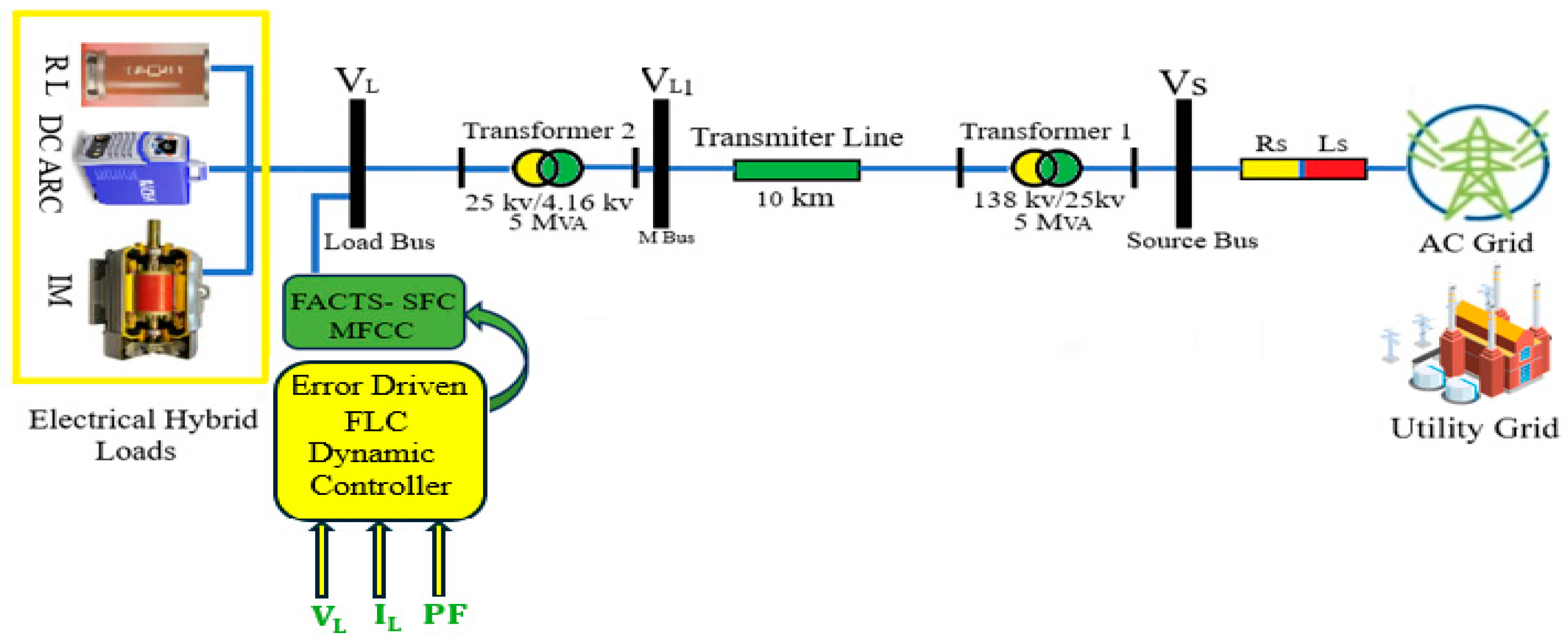
A single-line diagram of an AC system sample study of three-phase AC system supplying loads is shown in Figure 1. Figure 2 shows the FACTS-MFCC-SFC scheme of the AC three-phase system grid network. It represents the Simulink MATLAB software of the novel dynamic error-driven tri-loop FLC applied to lower switching transients, current inrush excursions, as well as in the low voltage utilization system for effective power/energy utilization and power quality improvement for the type of load depicted in [18].

Figure 1.
AC grid study system with hybrid loads and interface hybrid FACTS-switched filter system.
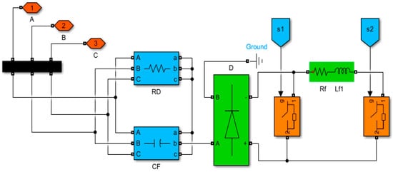
Figure 2.
The MFCC-SFC device.
The single-line diagram sample study of a three-phase AC system comprises a synchronous generator (driven by a source) that delivers the power to a local hybrid load (linear, DC ARC, and induction motor load) and is connected to an infinite bus through a 10 km transmission line. The main components of an AC system are as follows:
- A three-phase AC grid source;
- A novel modulated filter-capacitor compensator (MFCC-SFC) filter scheme;
- A novel dynamic error-driven tri-loop type-2 FLC;
- Three different electrical hybrid nonlinear loads;
- Transformers for voltage change from 138 kv to 25 kv and then from 25 kv to 4.16 kv.
The best way to ensure high efficiency is to minimize the active power loss during the power transmission process. Using active power loss reduction strategies with power factor regulation efforts can lead to a more efficient power transmission system [19]. At the same time, regulating the power factor (PF) is crucial during power transmission, as the PF contributes substantially to transmission efficiency (T.E.) [20]. Minimizing losses and maintaining reliability are crucial in providing end-consumers a stable and cost-effective electricity supply while also contributing to sustainable energy practices [21].
Transmission efficiency is the power obtained at the receiving end of a transmission line, which is generally less than the sending end power due to active power losses in the line resistance. The ratio of the receiving end power to the sending end power of a transmission line is known as the transmission efficiency of the line, as shown in Equation (1).
where are the receiving end voltage and current; cos is the receiving end power factor (lagging); are the sending end voltage and current; cos is the sending end power factor.
4. FACTS-MFCC-SFC Scheme
The proposed low-cost FACTS-MFCC-SFC dynamic voltage stabilization device is a member of the switched capacitor compensator and modulated switching/modulated power filter family [22]. Using a double-switched shunt capacitor bank and two shunt-linked fixed capacitors for the proposed FACTS-MFCC-SFC minimizes the overall harmonics distortion and improves power quality and the power factor. Moreover, the system’s ground is linked to a tuned arm filter to improve the overall performance. The FACTS-MFCC-SFC has two modes of operation: a capacitive compensation mode and a tuned arm filter mode that utilizes the controlled IGPT switches S1 and S2, as shown in Figure 2.
The MFCC filter acts as a modulated admittance and point of connection, usually near nonlinear loads. The duty cycle ratio is adjusted online using the multi regulation total error to ensure dynamic matching to fast- and slow-acting nonlinear variations. The dual function of the tuned arm filter is complemented by the adjusted capacitive compensation level for nonlinear reactive loads, motorized inrush loads, and cyclical loads.
5. Type-2 Fuzzy Logic Controller
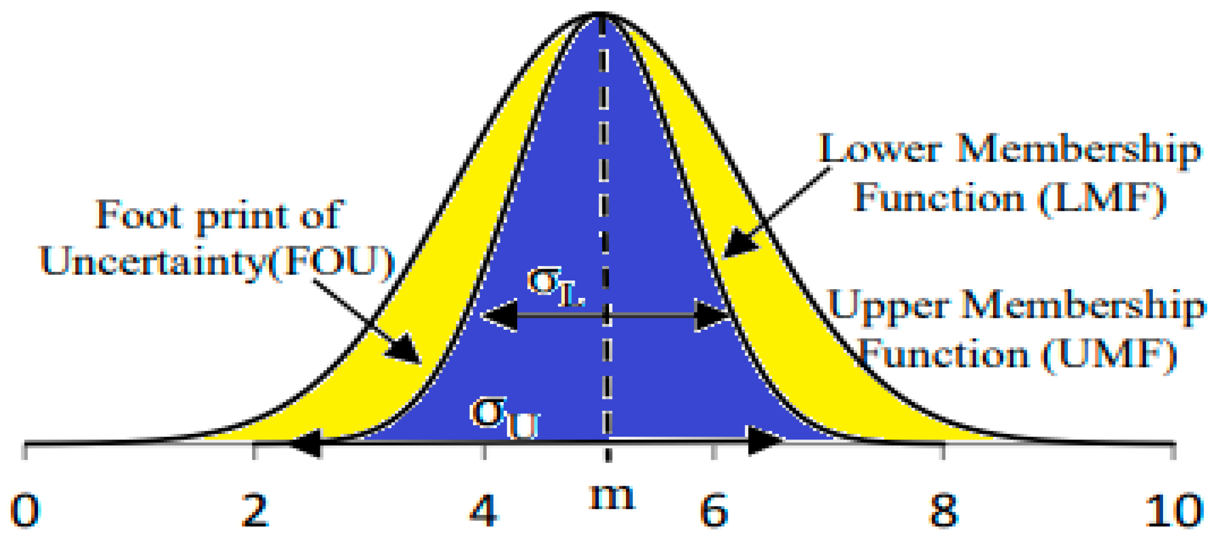
The fuzzy logic controller is flexible as it can deal with hidden nonlinearities in the loads and other inrush transient load behaviors. The flexibility is busted by fast response and tolerance to hidden nonlinear load dynamics [9]. The purpose of type-2 fuzzy logic, which is an expanded form of type-1 fuzzy logic, is to capture the ambiguities involved in defining type-1 fuzzy membership functions. To perform this task, a footprint of uncertainty is introduced in the type-1 fuzzy sets. Between the upper and lower fuzzy membership functions lies this ambiguous imprint. Consequently, when mapping real-world data using interval type-2 fuzzy sets, any such data will now have two degrees of membership [23]. The fuzzification procedure is now completed. The fuzzified lower and upper membership levels function according to rules, and each rule is assessed sequentially. Since there is additional encoded data, it is not possible directly accomplish defuzzification. As a result, a particular kind of reduction technique is presented to lessen the algorithm’s complexity. There are many other kinds of reduction algorithms, and the Karnik–Mendel technique is the most used one. Nevertheless, due to the complexity of this procedure, some computationally less expensive techniques have also been proposed. The same defuzzification process used for type-1 fuzzy logic is used to generate crisp value following this kind of reduction. In our study, we represent upper and lower fuzzy sets using triangle membership functions [24,25].
The main loops are used to keep the monitor out for any errors in the voltage or current of the bus. The controller’s time delay and scaling parameters are chosen using offline guided trial and error.
It is possible to mitigate any inrush, dynamic, sudden excursion changes that may appear in the bus voltage and current using the innovative tri-loop regulation set-up at the common source bus. In the meantime, loop decoupling in a dominant voltage stabilization loop is guaranteed by loop-weighing factors. This methodology guarantees a prompt reaction and a minimal quantity of errors in general. [26]. Using a modulated filter capacitive compensator, this method takes advantage of optimal switching based on system requirements. Furthermore, a fast PWM-modulated switching system consisting of a dynamic multi-regulation time-descaled error-driven controller is used for the green plug filter [27]. This design provides lower damped voltage transients, reduced inrush current ripple content, and dynamic interface bus voltage regulation by alternating between static capacitive compensation and the tuned arm filter. These situations can result from load switching, fluctuations in the wind pattern, self-excited capacitor banks within the system, and/or short-term faults in the SC and OC.
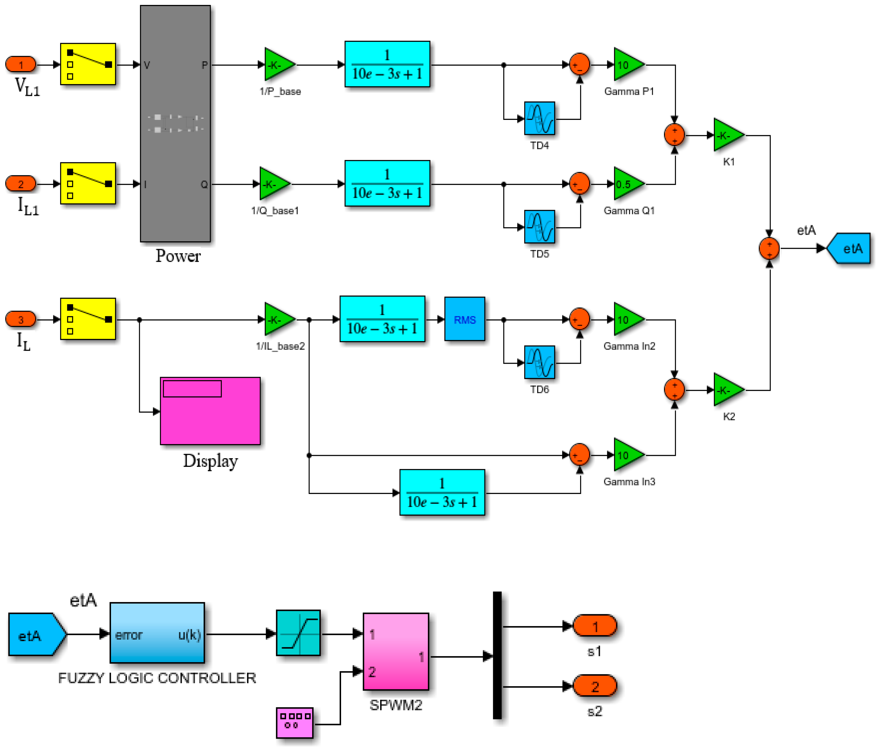
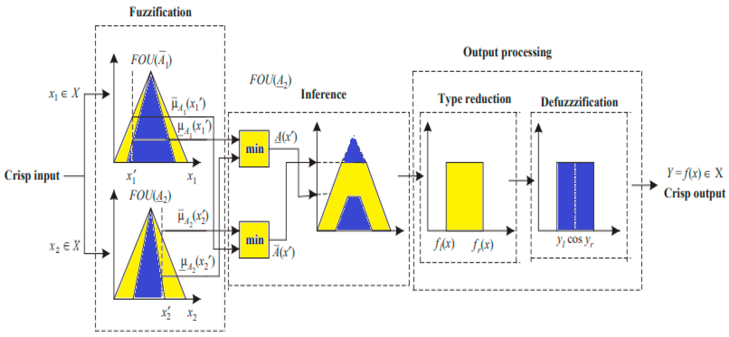
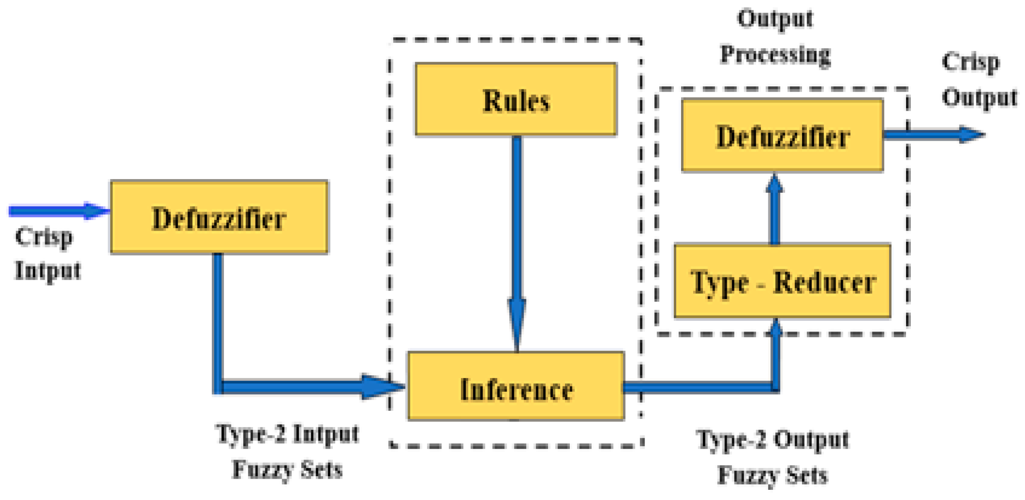
Dynamic controllers with extra loops are activated using an error sequential method. The dynamic quad-loop controller is made up of two main loops and two sub-loops, as shown in Figure 3. The inputs and/or outputs of the interval type-2 FLC are represented by interval type-2 fuzzy sets [28,29]. A real-time robot FLC design is made possible using interval type-2 FLC, which simplifies the calculation compared to the general type-2 FLC, which is computationally demanding [30]. The structure of an interval type-2 FLC and the fuzzifier, inference engine, rule base, type-reducer, and a de-fuzzifier are shown in Figure 4.
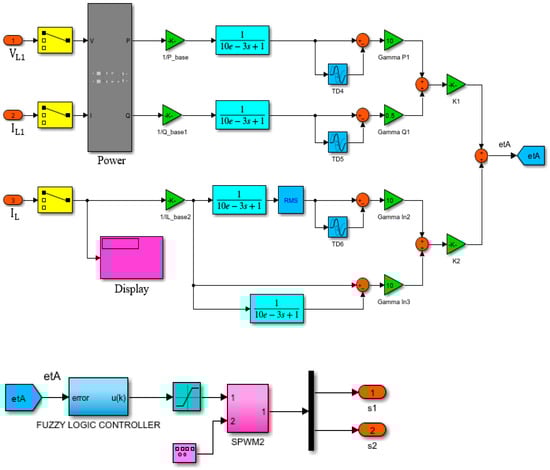
Figure 3.
Dynamic tri-loop tri-regulation controller for the AC SFC filter compensator.
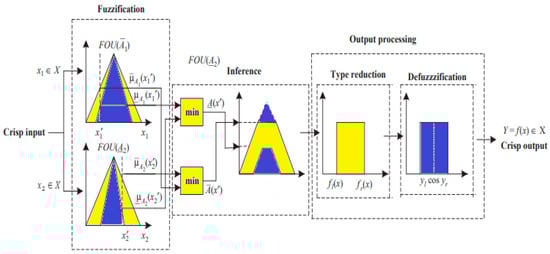
Figure 4.
Structure flow of interval type-2 fuzzy system.
The input type-2 fuzzy sets are created by fuzzifying the crisp inputs from the input sensors. Since singleton fuzzification is easy to apply and works well with embedded processors and real-time applications, it is typically employed in interval type-2 FLC applications [31]. The inference engine and the rule base are then triggered by the input type-2 fuzzy sets to generate output type-2 fuzzy sets, as shown in Figure 5 [32].
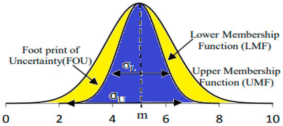
Figure 5.
An interval Gaussian type-2 fuzzy set.
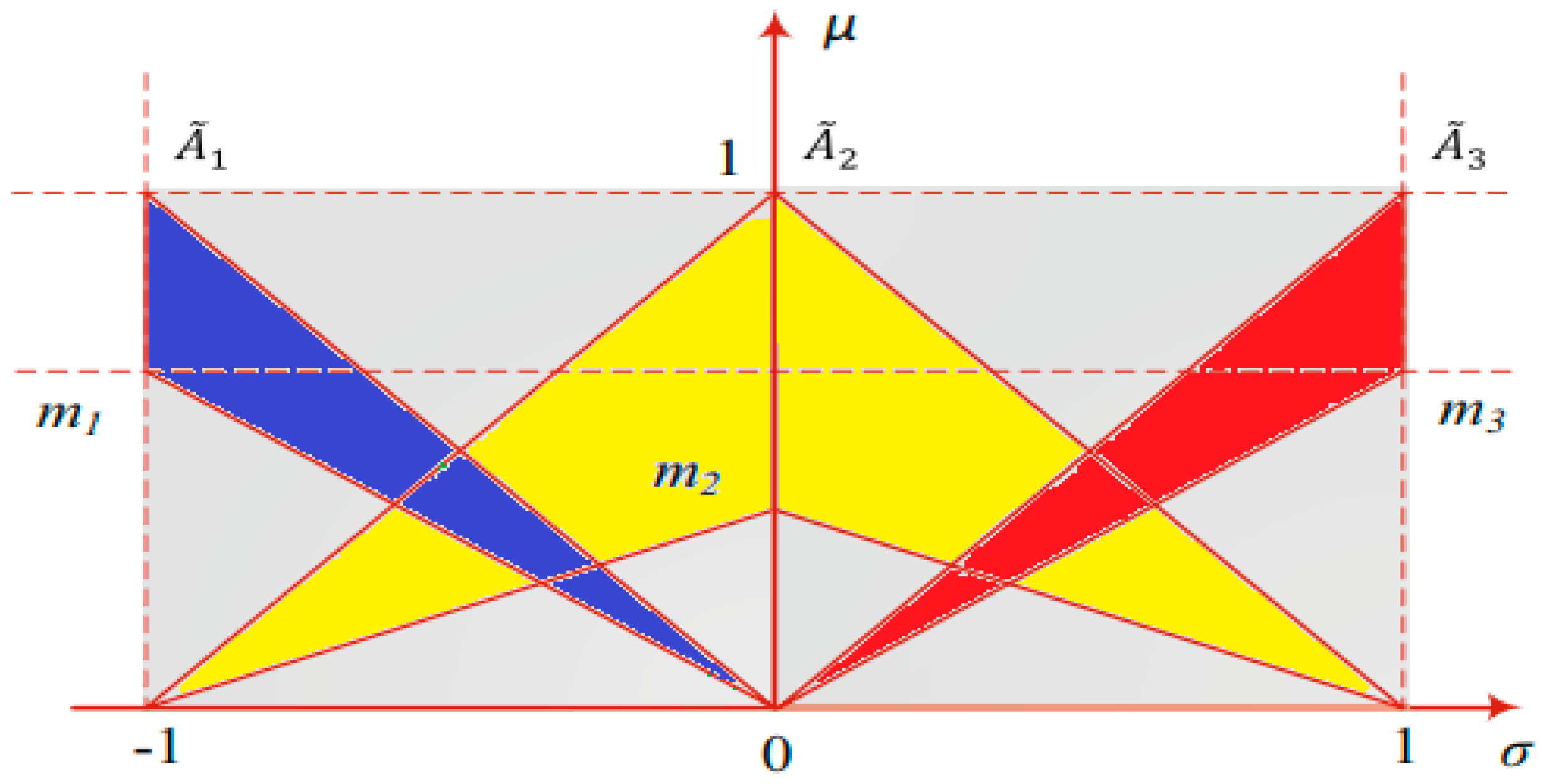
The rule structure of each S1-IT2-FLC is as follows, as shown in Figure 6:
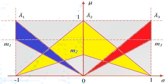
Figure 6.
Triangular IT2-FSs.
is described in terms of an upper membership function.
is described in terms of the lower membership function.
σ is the standard deviation.
represents crisp consequents 1, 2, and 3.
The equations describing the type-2 fuzzy logic are described as follows:
where represent the height of the lower membership function; Equation (3) describes the fuzzy rule base;
Equation (4) describes the type of reduction mechanism of a type-2 fuzzy controller.
where and are the end points of the type of reduced set, which are described as follows:
where are switching points.
Equation (5) describes the type of reduction mechanism of the type-2 fuzzy controller, as shown in Figure 6 and Figure 7.

Figure 7.
Type-2 fuzzy information processing.
6. Simulation Results and Discussion
Figure 8 shows the sample research AC system along with a certain supplementary component, FACTS-MFCC. It is connected to the infinite bus −138 kv and to a substation bus through the 10 km feeder, and it consists of a local hybrid load, which includes linear, nonlinear, and induction motor-type loads. Appendix A and Appendix B show the unified AC system, FACTS-MFCC, and the dynamic control parameters, respectively.
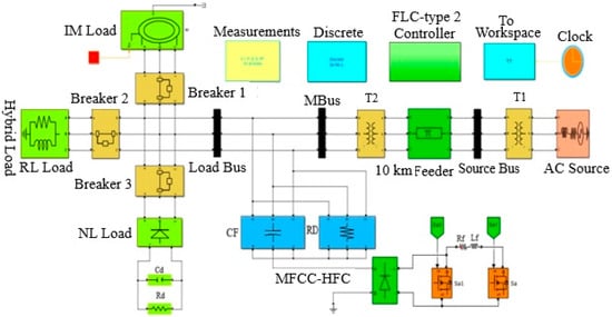
Figure 8.
Radial AC study system with FACTS -MFCC at load bus.
6.1. V, I, P, Q, and PF at Source Bus with Short Circuit Operation
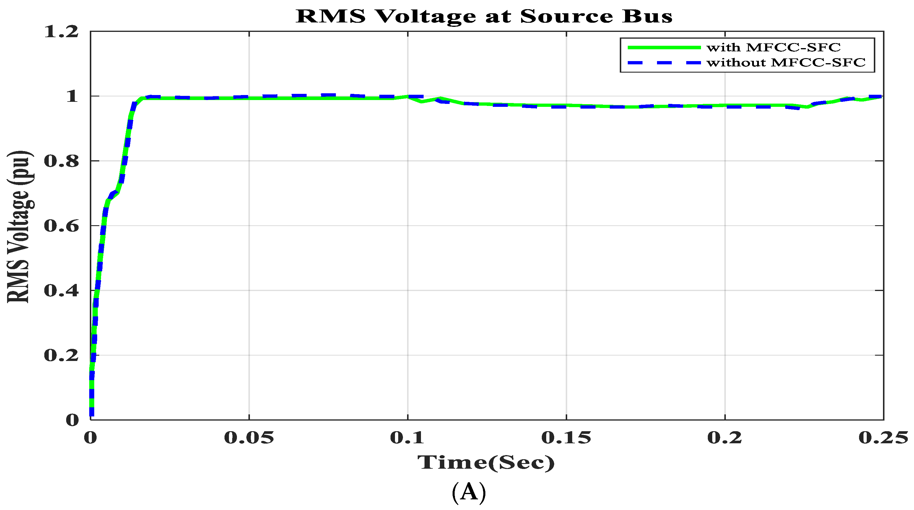
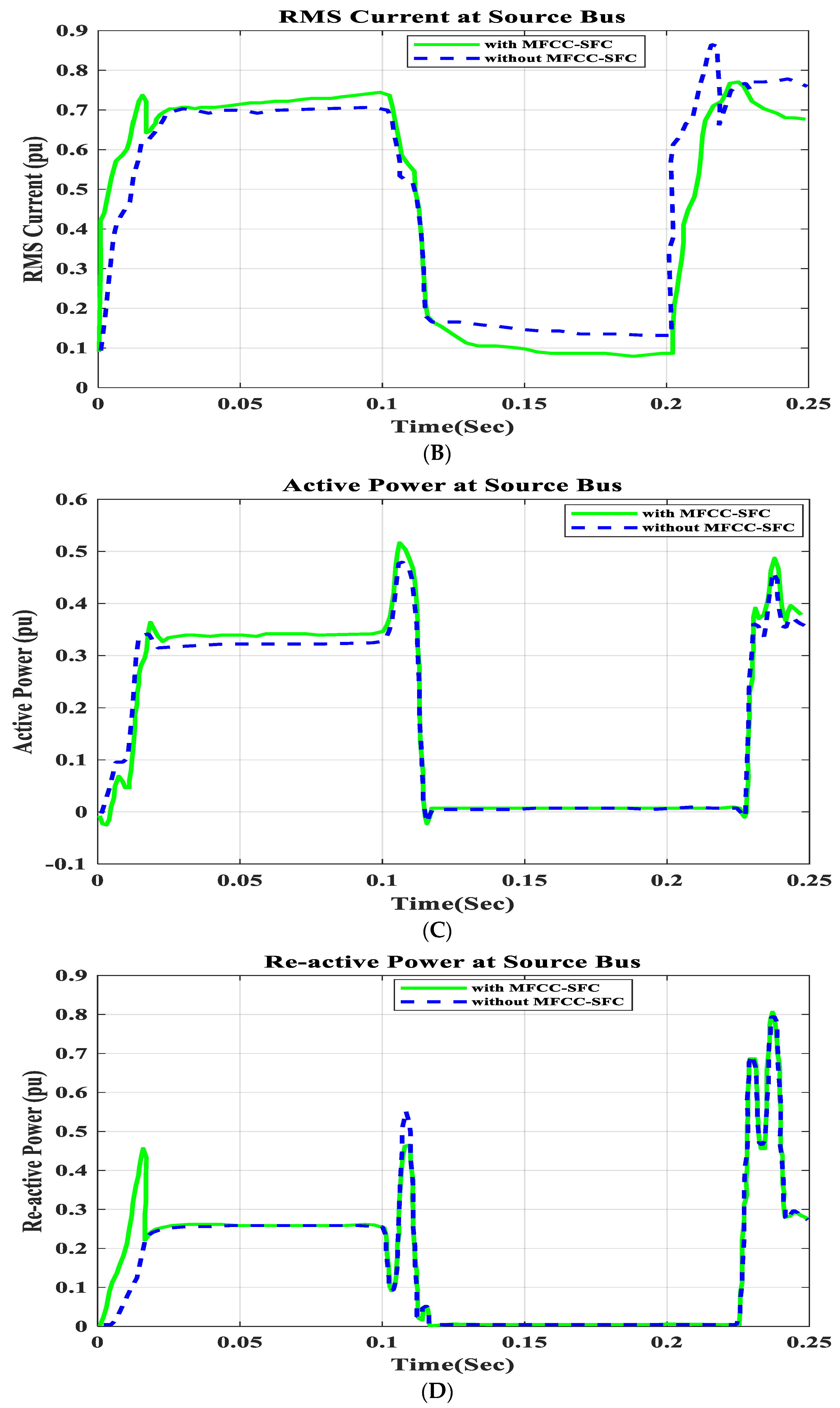
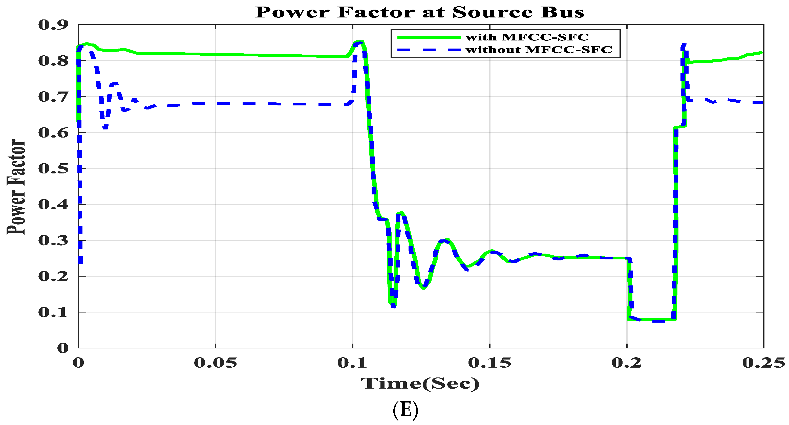
In this section the model is tested at source bus with short circuit for a duration of 100 ms to 200 ms and the voltage, current, active and reactive power and the power factor are calculated as seen in Figure 9.
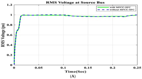
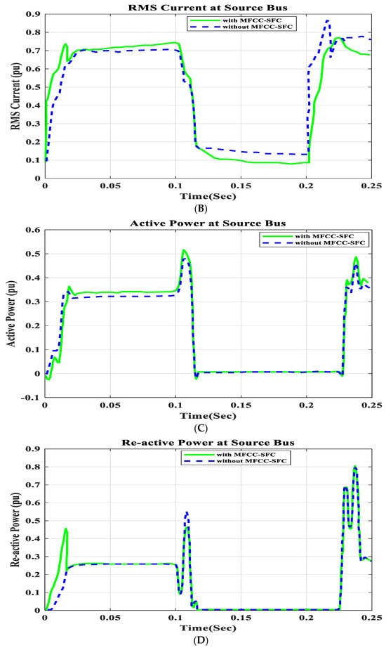
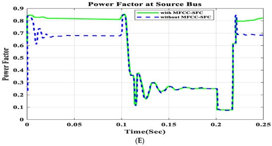
Figure 9.
V, I, P, Q, and PF at source bus with short circuit, duration of 100 ms to 200 ms. (A) RMS voltage waveform, (B) RMS current waveform, (C) active power waveform, (D) reactive power waveform, and (E) power factor waveform at source bus.
6.2. V, I, P, Q, and PF at Load Bus with Short Circuit Operation
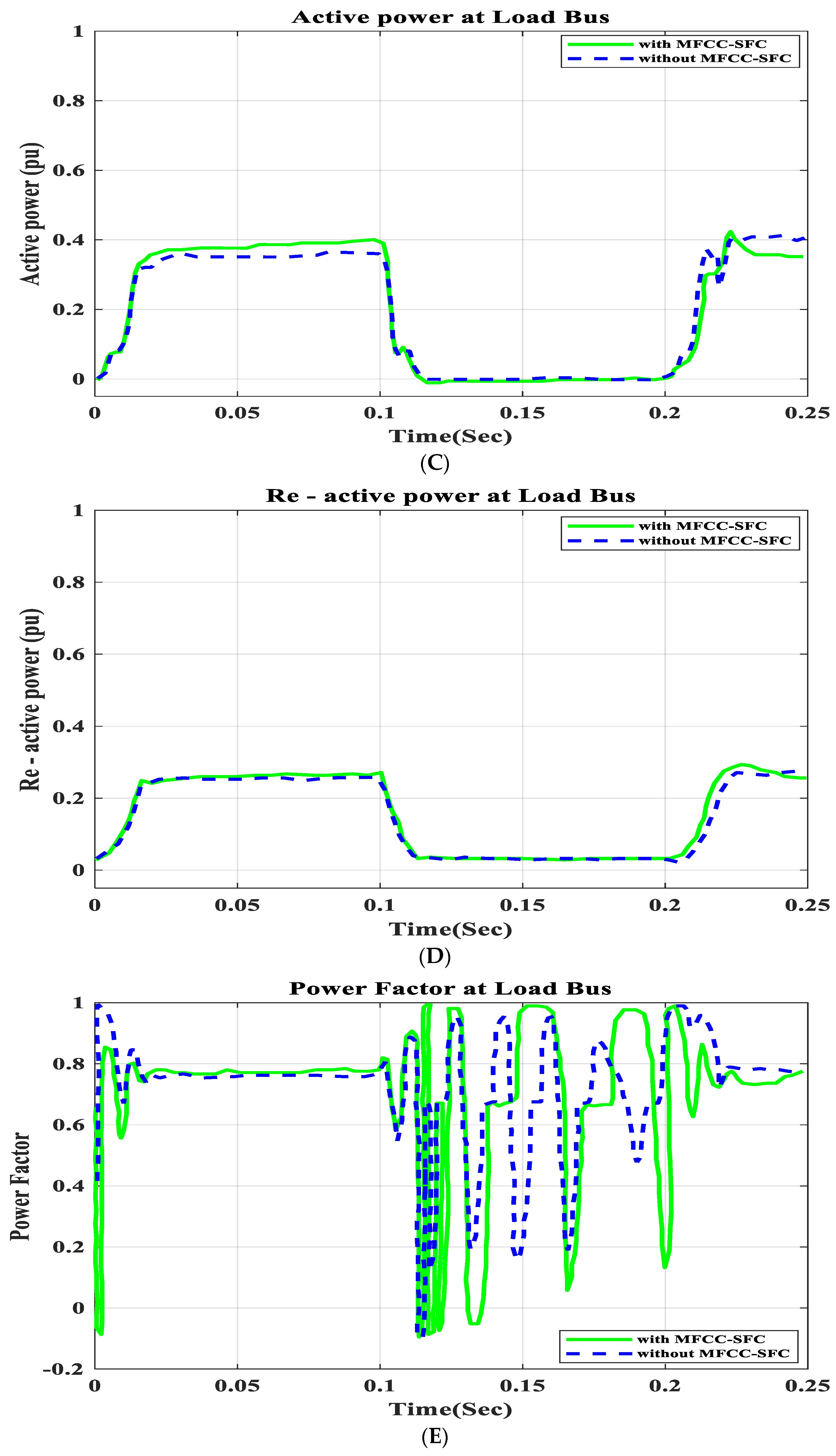
In this section the model is tested at the load bus with short circuit operation for a duration of 100 ms to 200 ms and the voltage, current, active and reactive power and the power factor are calculated as seen in Figure 10.
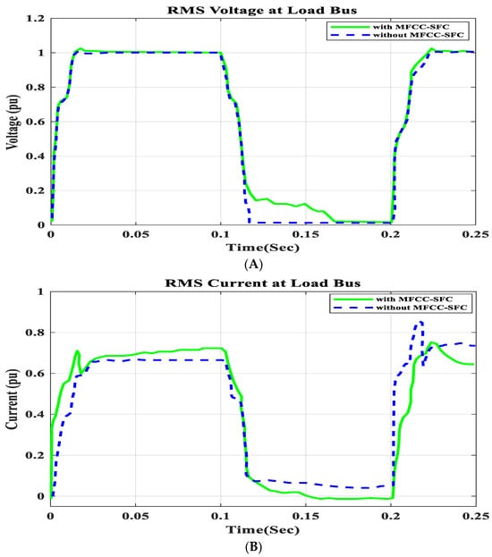
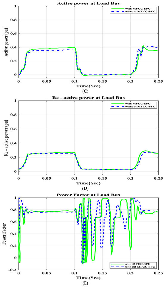
Figure 10.
V, I, P, Q, and PF at load bus with short circuit, duration of 100 ms to 200 ms. (A) RMS voltage waveform, (B) RMS current waveform, (C) active power waveform, (D) reactive power waveform, and (E) power factor waveform at load bus.
6.3. Application Short Circuit Condition
To demonstrate that the low-cost FACTS-MFCC scheme involving dynamic stabilization and efficient energy utilization works as intended, the proposed control schemes for stabilizing the host smart grid under a short circuit (SC), open circuit (OC), and other conditions were tested. All digital simulations used the MATLAB/SIMULINK-2023b software environment, which introduced a three-phase short circuit to the load bus of the AC grid at a time of 100 ms and cleared it after 200 ms. Figure 9 and Figure 10 demonstrate the outcomes of the simulations under the short circuit situation. Furthermore, the FACTS-MFCC-SFC scheme improved its efficiency in lowering inrush currents during short- and open-circuit failures, which helped enhance the power factor and stabilize bus voltages in the case study.
6.4. V, I, P, Q, and PF at Source Bus with Open Circuit Operation
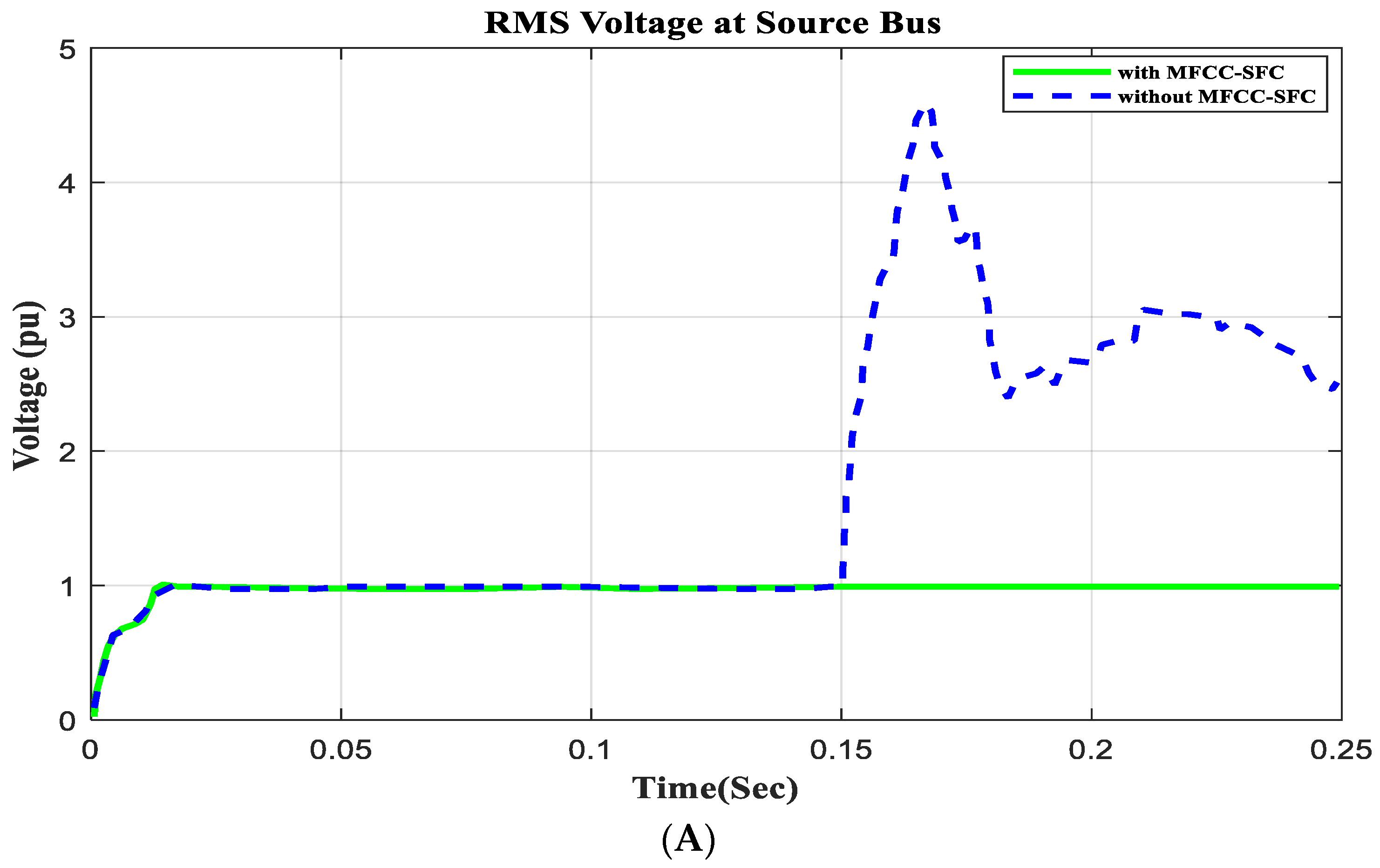
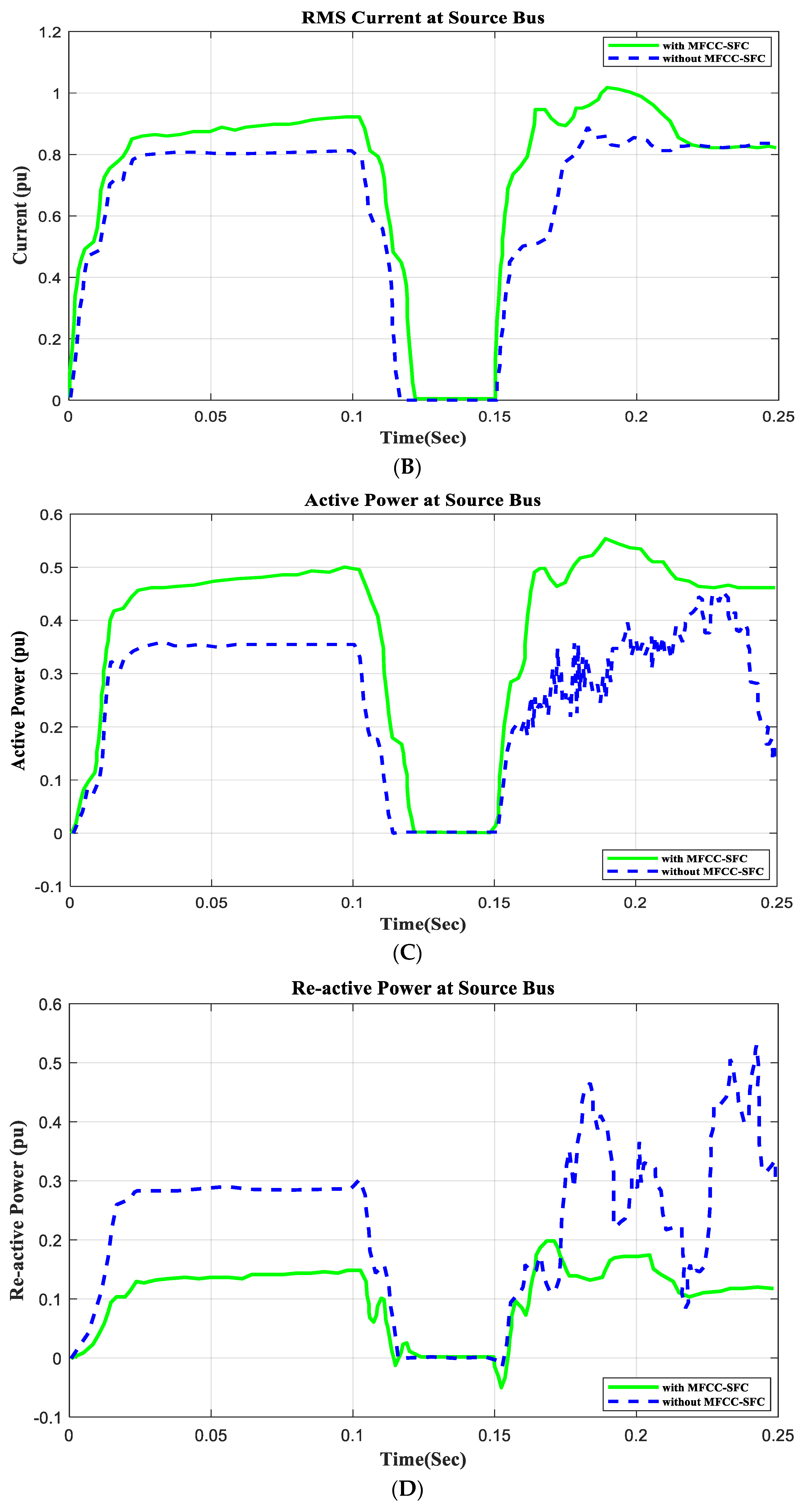
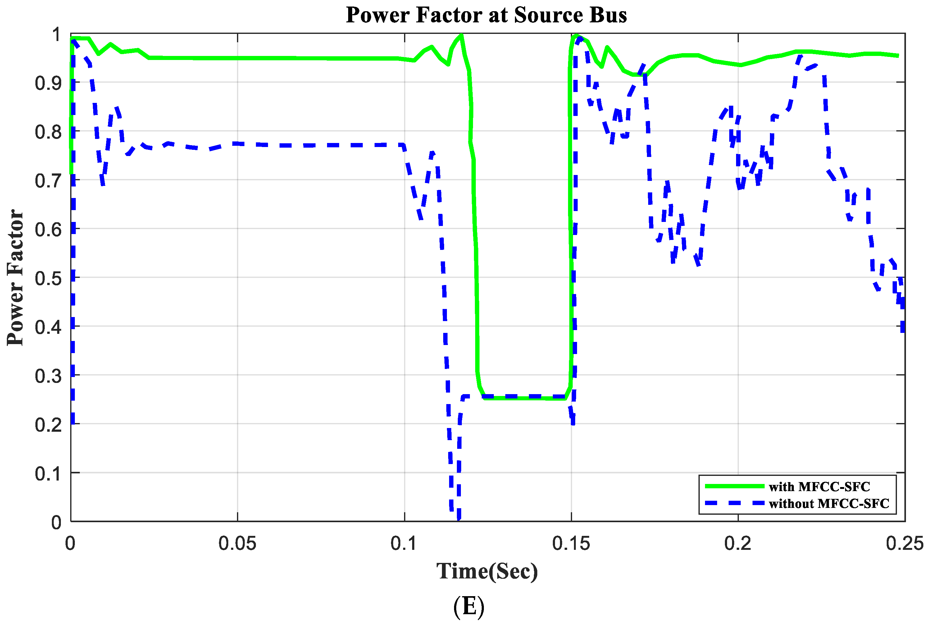
In this section the model is tested at the source bus with open circuit operation for a duration of 100 ms to 150 ms and the voltage, current, active and reactive power and the power factor are calculated as seen in Figure 11.
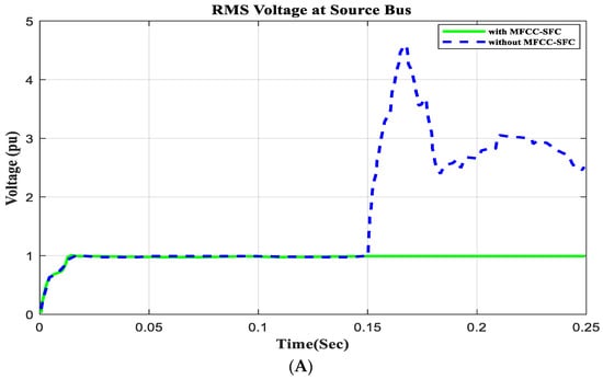
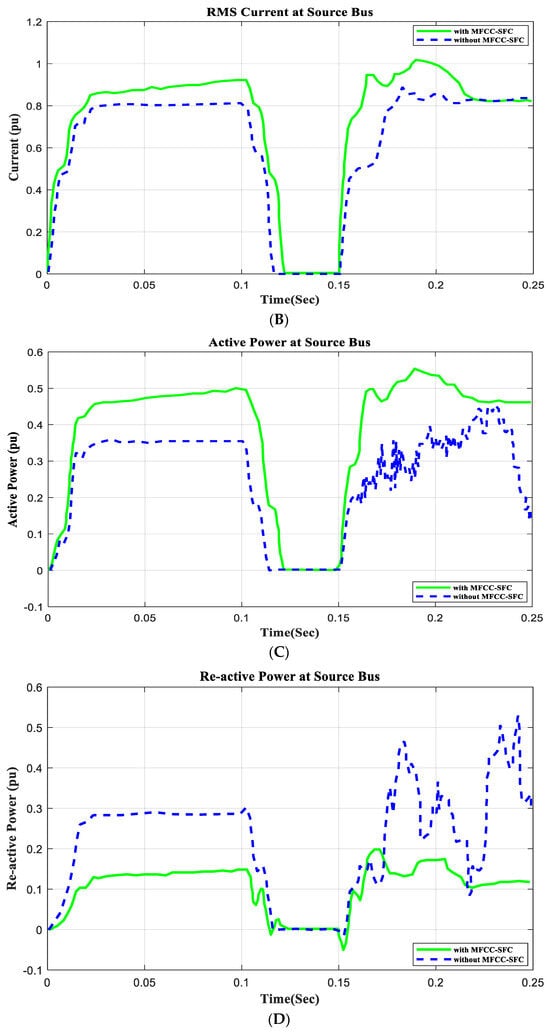
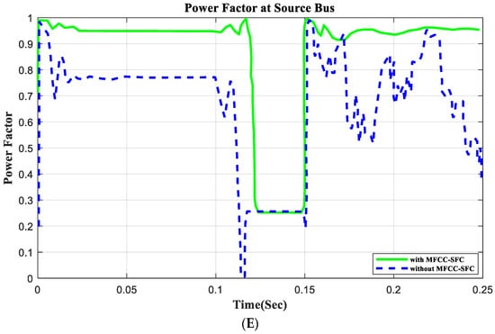
Figure 11.
V, I, P, Q, and PF at source bus with open circuit, duration of 100 ms to 150 ms. (A) RMS voltage waveform, (B) RMS current waveform, (C) active power waveform, (D) reactive power waveform, and (E) power factor waveform at source bus.
6.5. V, I, P, Q, and PF under at Load Bus with Open Circuit Operation
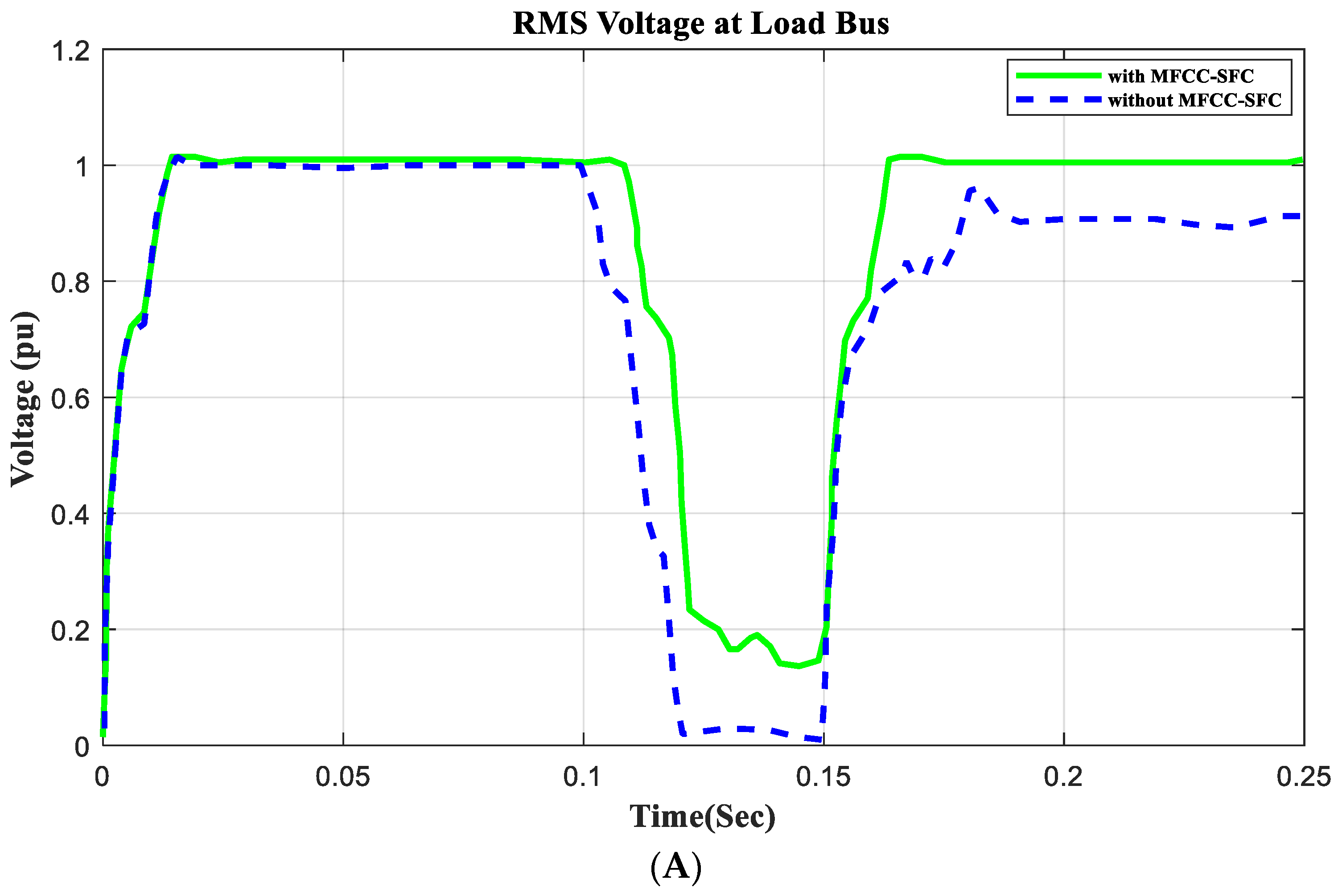
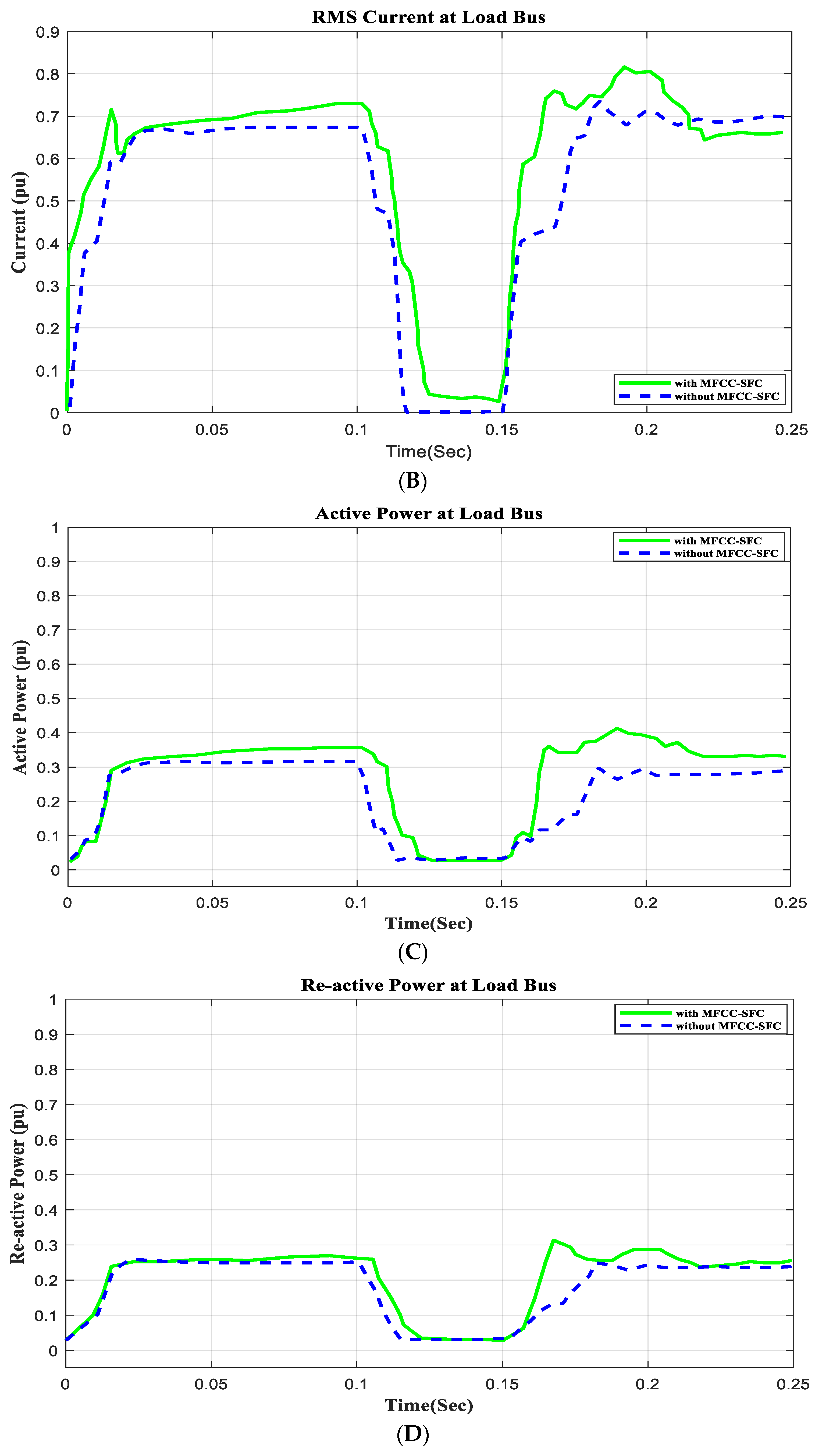
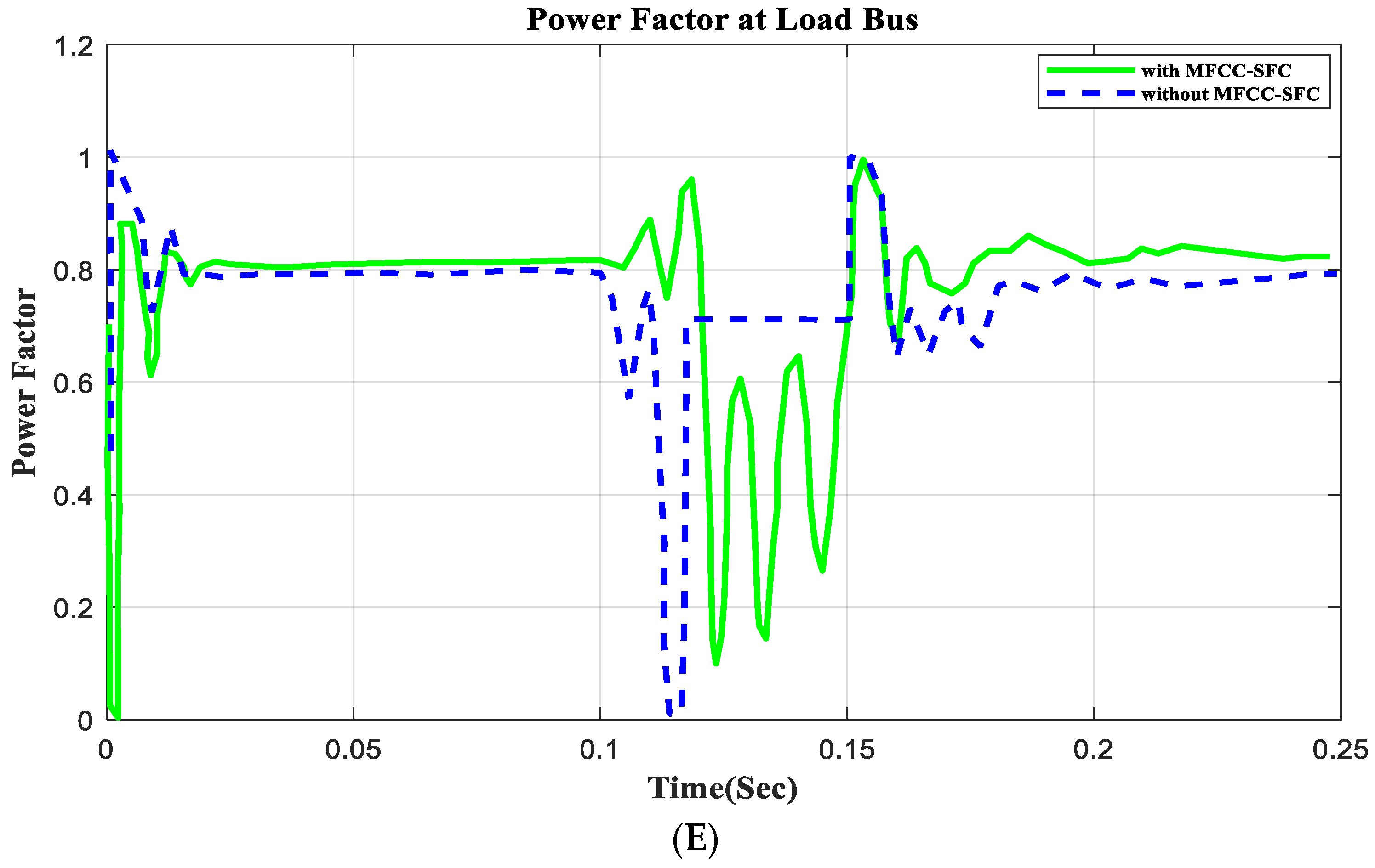
In this section the model is tested at the load bus with open circuit operation for a duration of 100 ms to 150 ms and the voltage, current, active and reactive power and the power factor are calculated as seen in Figure 12.
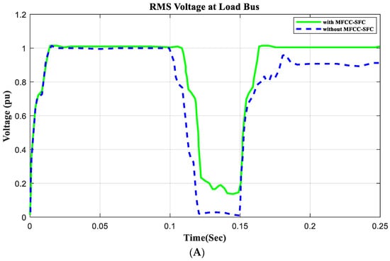
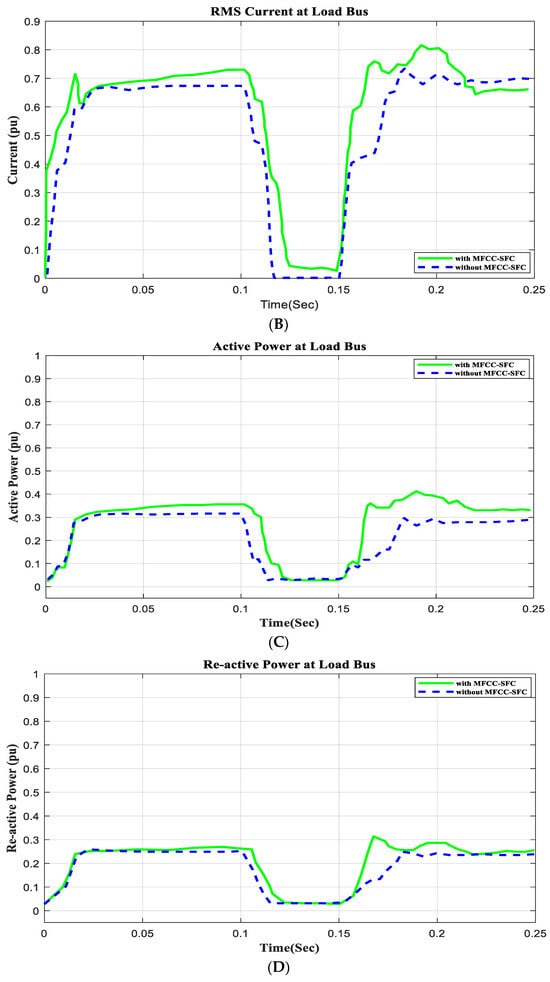

Figure 12.
V, I, P, Q, and PF at load bus with open circuit, duration of 100 ms to 150 ms. (A) RMS voltage waveform, (B) RMS current waveform, (C) active power waveform, (D) reactive power waveform, and (E) power factor waveform at load bus.
6.6. Application of Open Circuit Condition
In this section, an open circuit occurs close to the load, and the alteration in a critical parameter is demonstrated. All digital simulations used the MATLAB/SIMULINK-2023b software environment, which introduced a three-phase open circuit to both buses (source and load) of the AC grid at a time of 100 ms and cleared it after 150 ms. Figure 11 and Figure 12 demonstrate the outcomes of the simulations under the open-circuit situation. Furthermore, as can be seen, both buses (source and load) now have better dynamic response and power quality. Additionally, there are not many fluctuations in the power factor in open-circuit faults with FACTS-MFCC-SFC in essential buses, particularly in source buses.
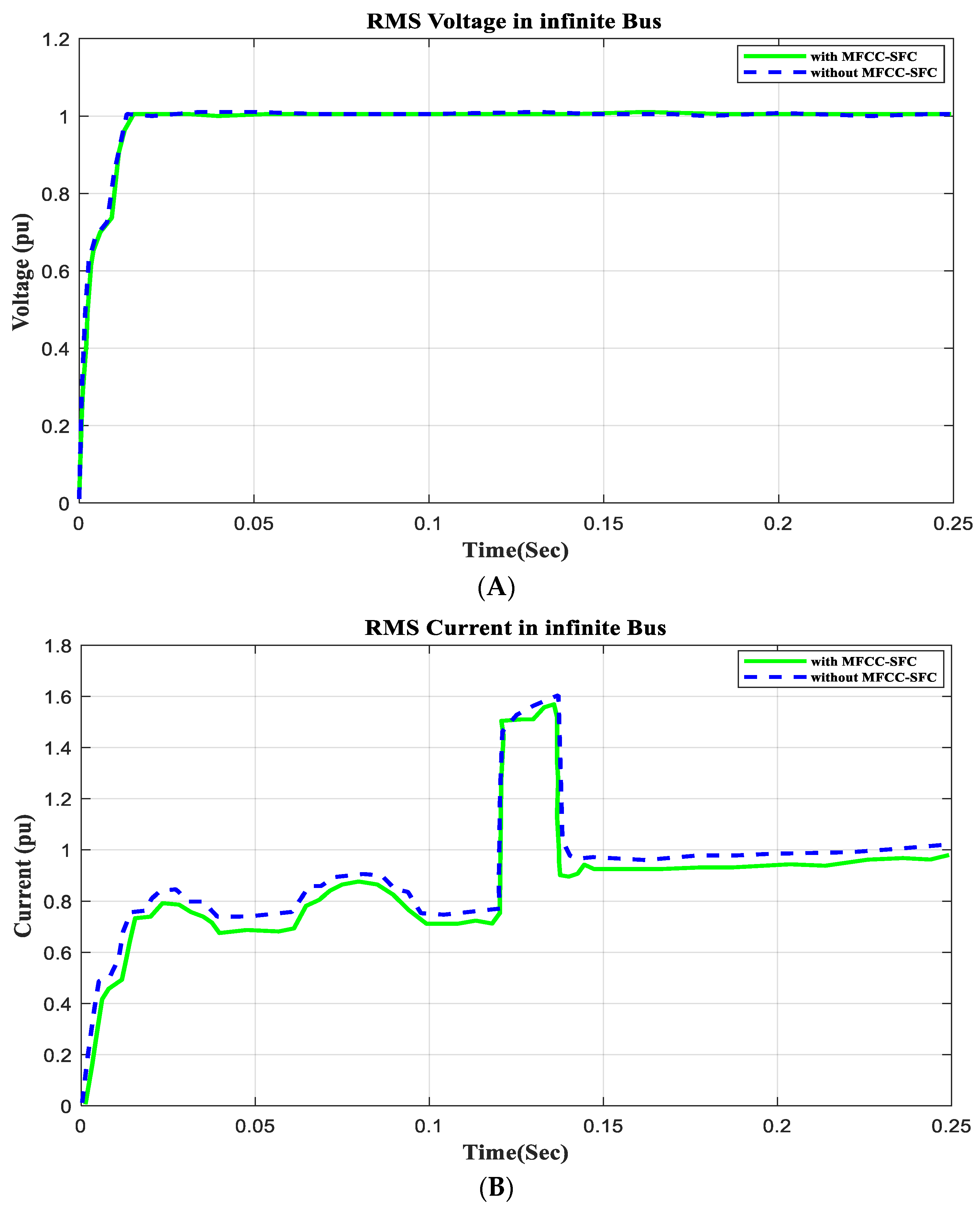
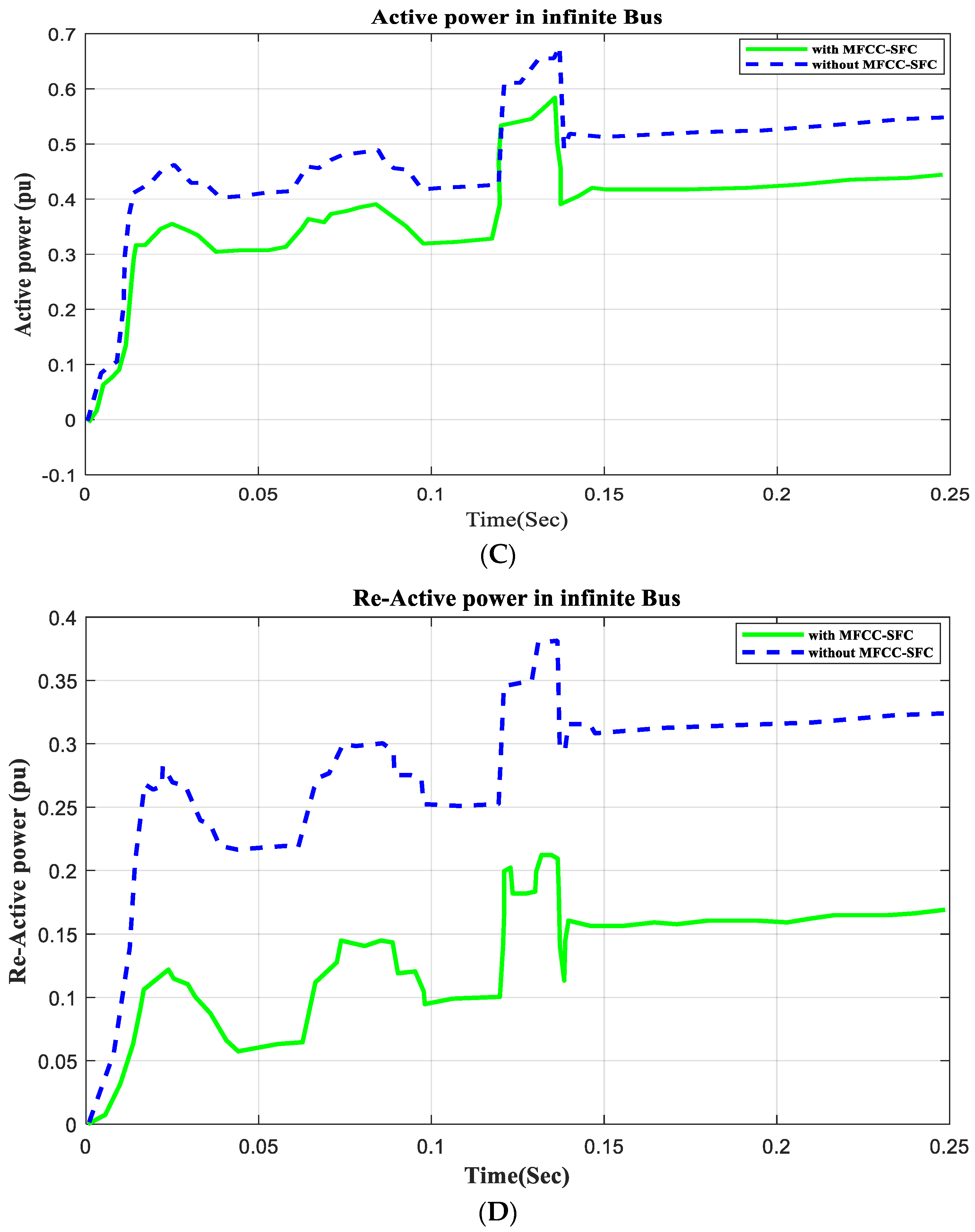
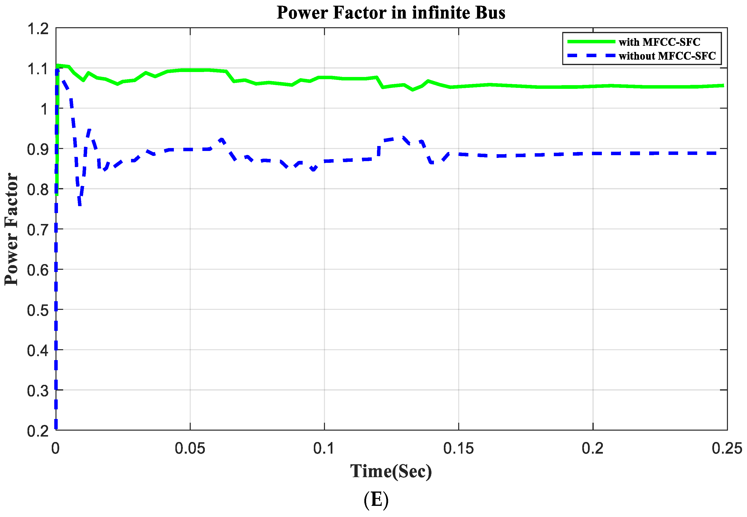
6.7. V, I, P, Q, and PF in Infinite Bus
In this section the model is tested at the infinite bus with open circuit operation for a duration of 100 ms to 150 ms and the voltage, current, active and reactive power and power factor are calculated as seen in Figure 11.
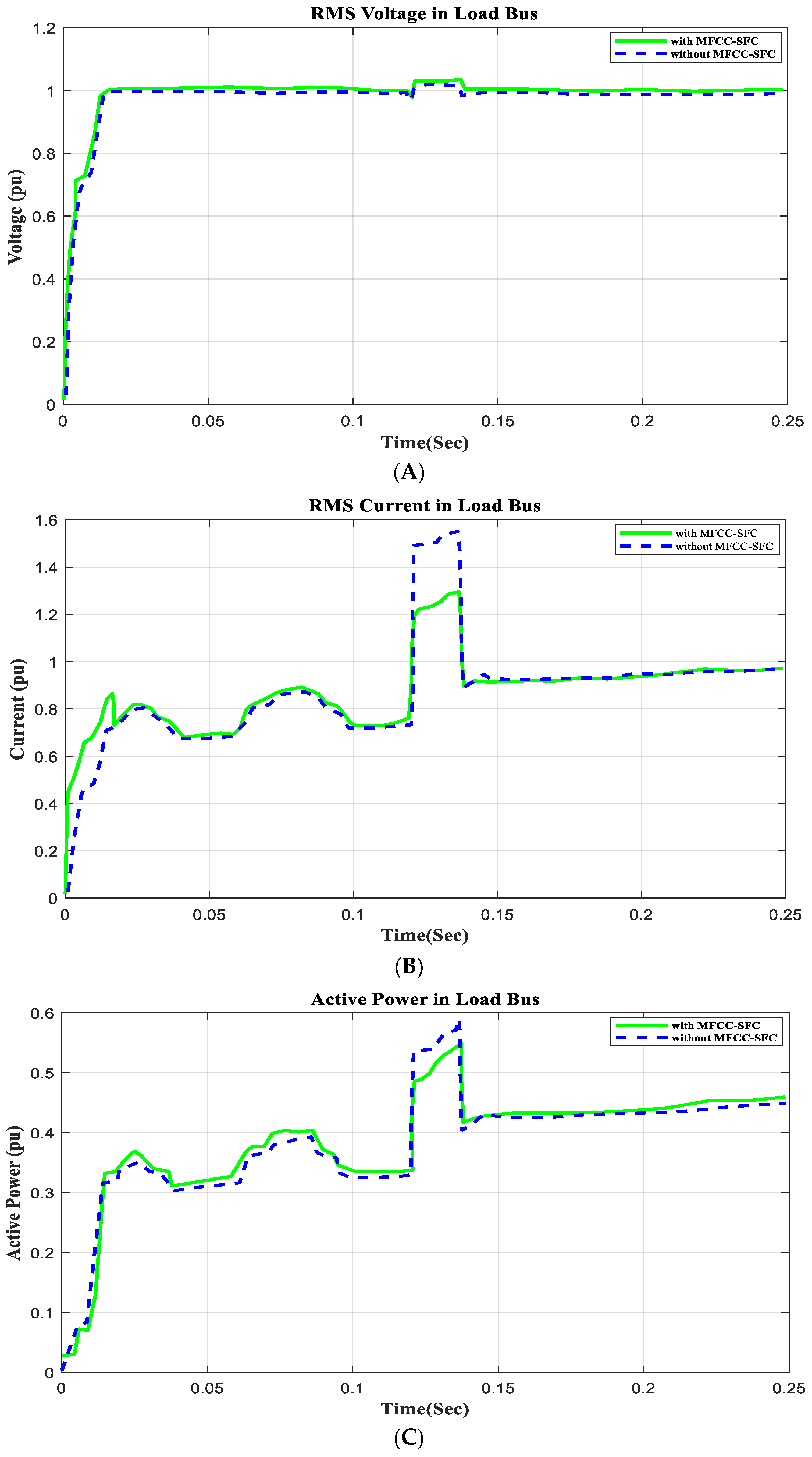
6.8. V, I, P, Q, and PF in Load Bus
In this section the model is tested at the load bus with open circuit operation for a duration of 100 ms to 150 ms and the voltage, current, active and reactive power and power factor are calculated as seen in Figure 12.
7. Open and Close Circuits
We used the on/off breakers, as seen in the Simulink model; the position of the breaker in the series was close to the ground at the open circuit and parallel at the short circuit, and the operations for both the open circuit and short circuit were carried out at the AC source and load bus for a short-circuit duration of 100 ms to 200 ms and an open-circuit duration of 100 ms to 150 ms, as shown in Table 1 and Table 2. Figure 9 shows the V, I, P, Q, and PF at the source side with short-circuit operation, and Figure 10 shows the V, I, P, Q, and PF at the load side with short-circuit operation at 100 ms to 200 ms. Figure 11 shows the V, I, P, Q, and PF at the source side with open-circuit operation, and Figure 12 shows the V, I, P, Q, and PF at the load side with open-circuit operation at 100 ms to 150 ms.

Table 1.
Voltage, current, active power, and power factor values at source and load buses without and with MFCC device under SC.
Table 2.
Voltage, current, active power, and power factor values at source and load buses without and with MFCC device under OC.
8. Hybrid Load Variations
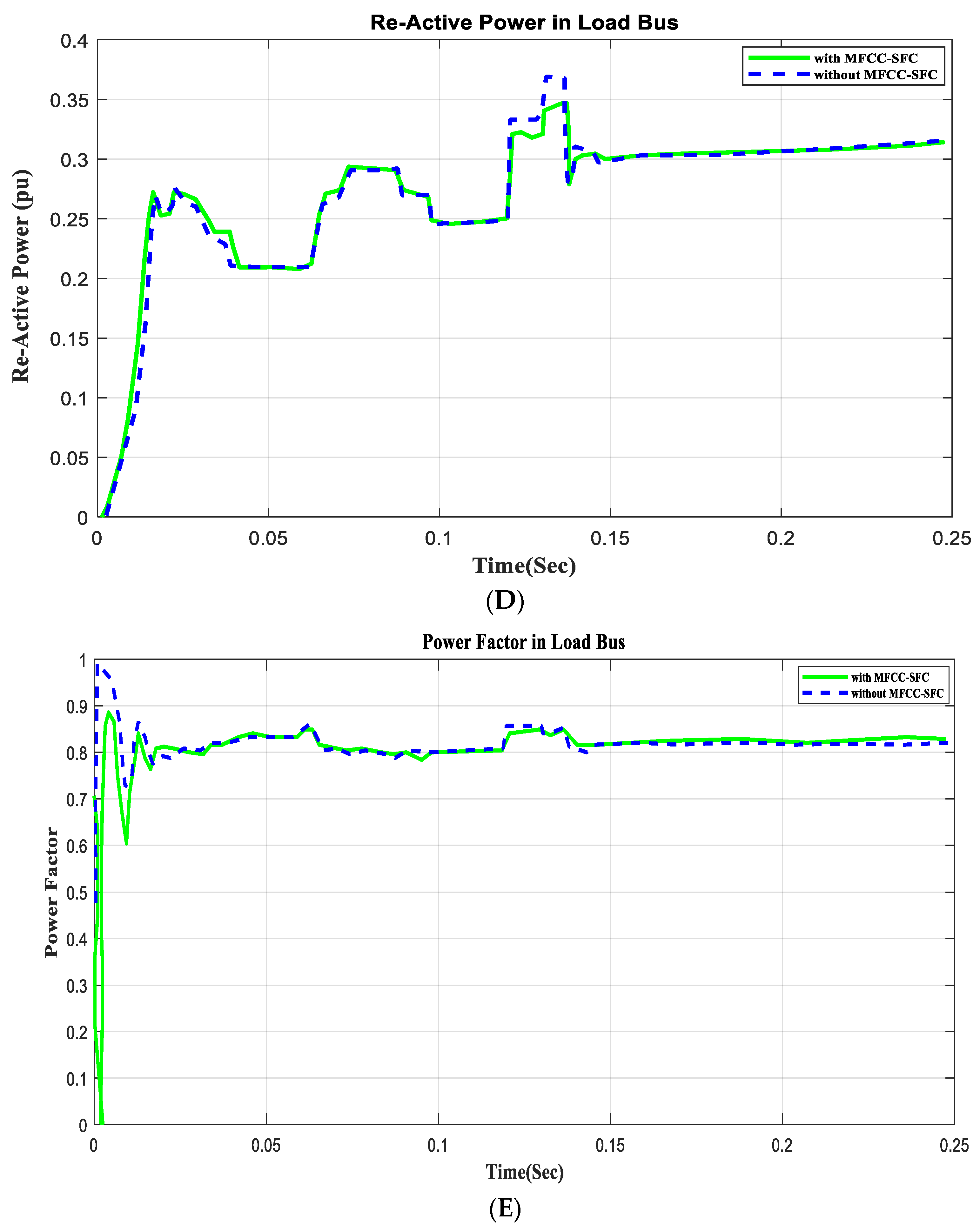
The grid is subjected to the following situations in order to study how the AC grid reacts to load excursions both with and without the FACTS-MFCC. The results for both the current and voltage values are shown in Figure 13 and Figure 14. Linear pressure is disconnected at 117 ms and then reconnected at 134 ms. Nonlinear demand is disconnected at 100 ms and then reconnected at 45 ms. The motor load torque drops at 170 ms by 50% and continues for a duration of 45 ms. The motor load torque rises by 50% at 250 ms seconds for a duration of 45 ms.
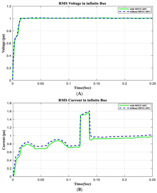
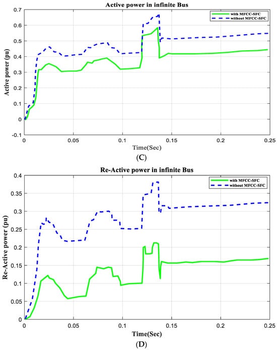
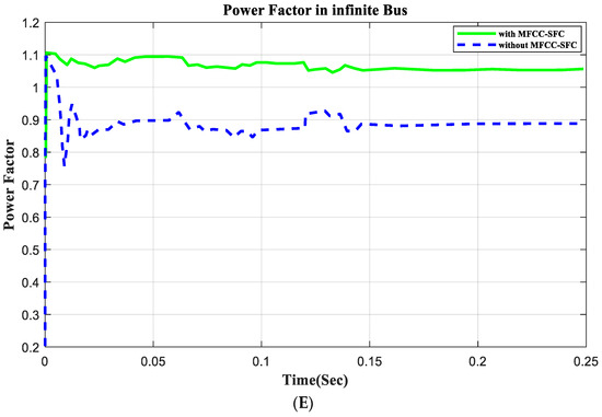
Figure 13.
V, I, P, Q, and PF at infinite bus with open circuit, duration of 100 ms to 150 ms. (A). RMS voltage waveform, (B) RMS current waveform, (C) active power waveform, (D) reactive power waveform, and (E) power factor waveform in infinite bus.
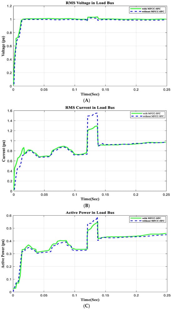
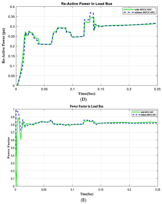
Figure 14.
V, I, P, Q, and PF at load bus with open circuit, duration of 100 ms to 150 ms. (A) RMS voltage waveform, (B) RMS current waveform, (C) active power waveform, (D) reactive power waveform, and (E) power factor waveform in load bus.
9. Power System Harmonics Analysis
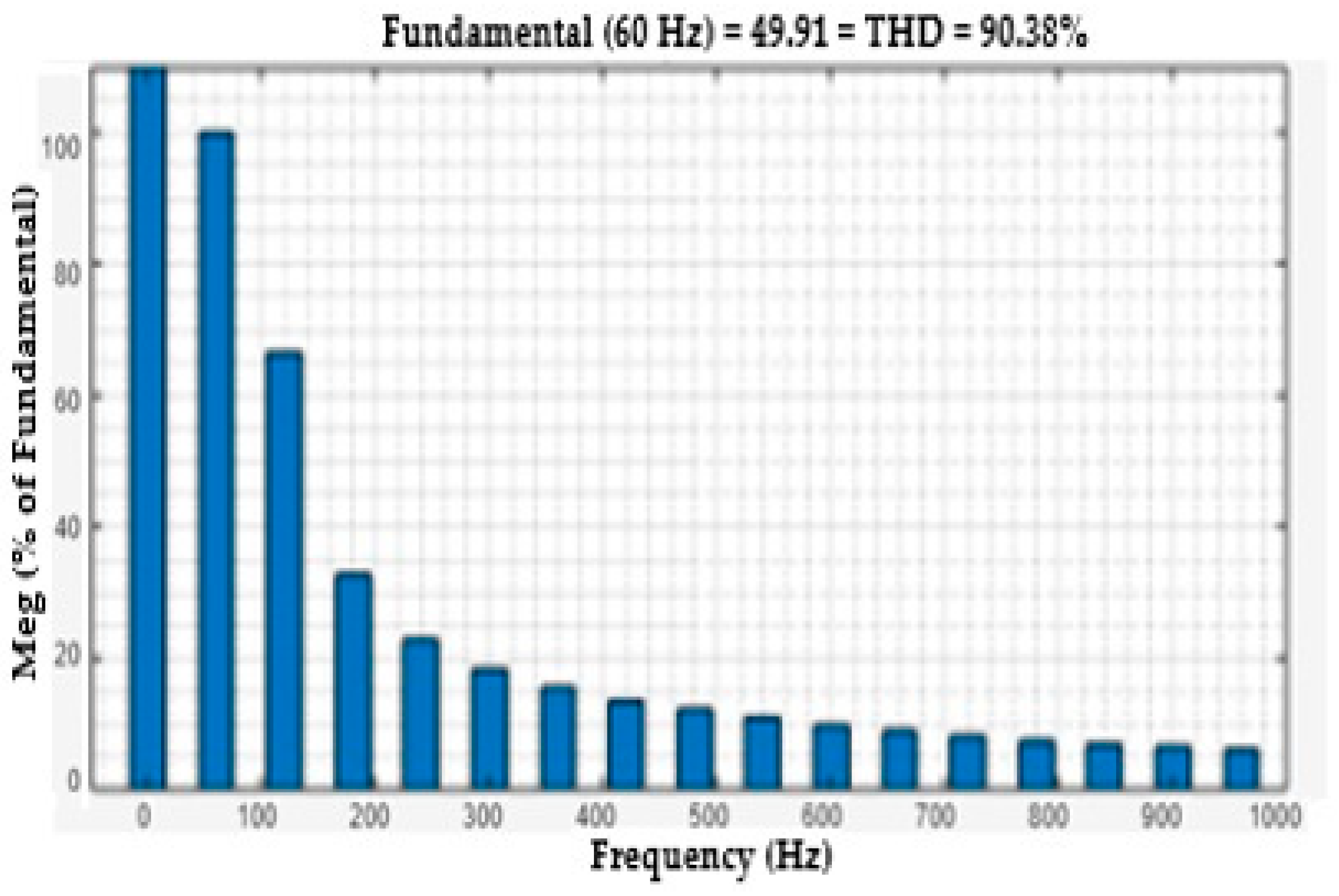
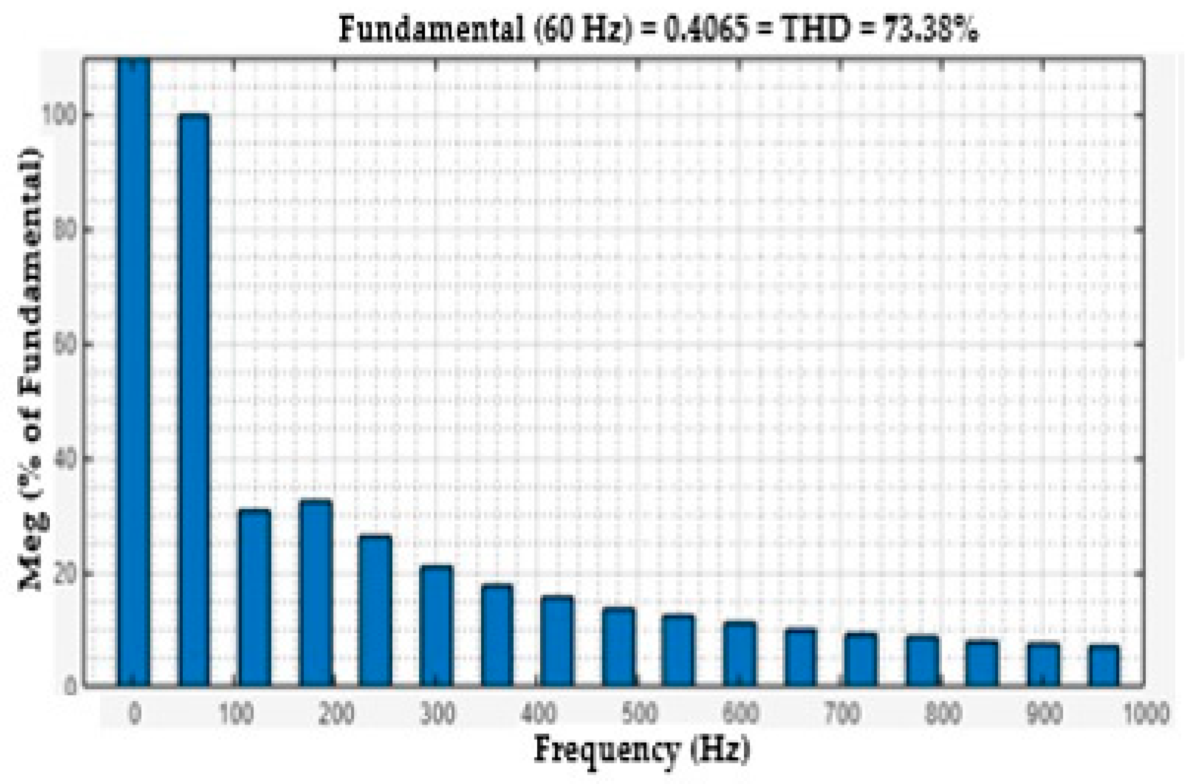
One useful metric for estimating the harmonics in voltage or current waveforms is the total harmonic distortion or THD. The harmonics effect of the voltage and current load bus are discussed in this section. The voltage THDs of the load bus without FACTS-MFCC-SFC as a function of time is seen in Figure 15. The rate of THD increased for constant series compensation, as shown in Figure 15, because the nonlinear loads are used on power systems; however, the THD of the voltage in the load bus was improved, as shown in Figure 16, by employing the FACTS-MFCC-SFC. The current THDs of the load bus without FACTS-MFCC-SFC as a function of time is seen in Figure 17. The rate of THD increased for constant series compensation, as shown in Figure 17 because the nonlinear loads are used on power systems; however, the THD of the current in the load bus was improved, as shown in Figure 18, by employing the FACTS-MFCC-SFC [33]. All variables values are shown in Appendix A and Appendix B.
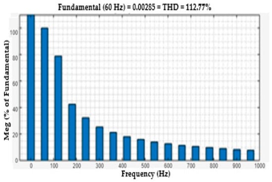
Figure 15.
FFT analysis of voltage at load bus without FACTS-MFCC for load-changing operation.

Figure 16.
FFT analysis of voltage at load bus with FACTS-MFCC for load-changing operation.
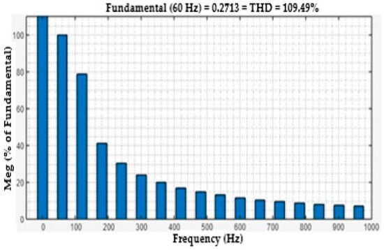
Figure 17.
FFT analysis of current at load bus without FACTS-MFCC for load-changing operation.
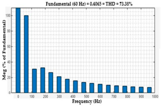
Figure 18.
FFT analysis of current at load bus with FACTS-MFCC for load-changing operation.
10. Discussion of Digital Simulation Results
There are many reasons to propose a new device, and the use of the low-cost structure of the dual-mode modulated filter is necessitated by the need for a dual-tuned arm filter plus capacitive compensation for dynamic inrush nonlinear loads. The function of the modulated pulse width duty cycle switching scheme is to dynamically cater the nonlinear loads and inrush current variations and reactive compensation tasks to stabilize the AC voltages at key load buses with FACTS-MFCC-SFC, as shown in Table 1 and Table 2.
11. Conclusions and Extended Work
This paper validates the concept of an AC plug switched filter modulated action using pulse width modulation based on a multi-loop self-adjusted modified weighted PID structure controller and FLC. The modulated filter AC green plug ensures enhanced efficient operation, power quality, reduced harmonics, and improved power factor operation at nonlinear-type motorized inrush and rectifier nonlinear loads. For strong interfacing to the smart AC grid, the same filter structure MFCC-SFC device with different control techniques is currently being extended for hybrid renewable wind and micro-hydro green energy systems and applications, such as using virtual inertia static synchronous machines and Energy Storage System (ESS) DC-AC utility grid systems. The digital simulation results validate the quick flexibility and efficiency of the proposed FACTS-MFCC-SFC scheme in improving voltage regulation, reducing inrush current conditions, and altering the power factor. The AC green plug filter is validated as an effective voltage stabilization and power factor improvement tool in the case of slow-dynamic-nonlinear- and inrush-type loads. The PWM switching modulation index is dynamically modified to modulate the tuned arm filter apparent admittance and capacitive VAR compensation level using the multi-loop multi-regulation fuzzy logic fast dynamic controller. The fuzzy logic fast dynamic multi-loop multi-regulator controller was validated as an effective tool in voltage stabilization, power factor improvement, and power quality enhancement.
Author Contributions
Conceptualization; methodology; software, A.M.B.; validation, A.M.B. and A.M.S.; formal analysis; investigation; resources, A.M.B., M.A., A.M.S. and H.H.A.; a curation, A.M.B. and H.H.A.; writing—original draft preparation, A.M.B. and M.A.; writing—review and editing; visualization, A.M.B. and H.H.A.; supervision, A.M.S., H.H.A. and J.G.; project administration, A.M.S., H.H.A. and J.G. All authors have read and agreed to the published version of the manuscript.
Funding
This research received no external funding.
Data Availability Statement
The data presented in this study are available on request from the corresponding author. The data are not publicly available due to its confidentiality.
Conflicts of Interest
The authors declare no conflict of interest.
Appendix A. System Specifications
| Parameters | Value |
| AC Utility Grid Parameters | |
| Nominal Voltage | 138 kv (L-L), 100 MW |
| Ratio X/R | 10 |
| Base Power Vs Bus | 100 MVA |
| Base Power VL Bus | 200 MVA |
| Frequency | 1.750 KHz |
| FACTS-MFCC Parameters | |
| 275 µF | |
| , , | 1 Ω, 0.15 Ω, 3 mH |
| Width Modulation Proportional Integral Derivative (WMPID) Controller Parameters | |
| Ke, Kp, , , , | 0.7, 5, 1.5, 0.5, 0.5, 0.1 |
| Transmission Line | |
| Feeder | 25 kv (L-L),10 km |
| R/km, L/km | 0.4 Ω, 0.45 Ω |
Appendix B. Transformer, Motor and Load Specifications
| Parameters | Value |
| Transformer Parameters | |
| Power Transformer 1 | 138 kv to 25 kv, 5 MW |
| Power Transformer 2 | 25 kv to 4.16 kv, 5 MW |
| Hybrid AC Load Parameters | |
| Induction Motor | 2.5 MVA, 4 poles |
| Rs = 0.02765 pu, Ls = 0.0498 pu | |
| Rr = 0.01807 pu, Lr = 0.0497 pu | |
| Lm = 1.354 pu | |
| Linear Load | P = 2500 KW, Q = 2 MVAr |
| Nonlinear Load | P = 1250 KW, Q = 2 MVAr |
References
- Kazemi-Robati, E.; Hafezi, H.; Sepasian, M.S.; Silva, B. Probabilistic planning of virtually-hybrid harmonic filters inmodern distribution systems. In Proceedings of the 2023 International Conference on Smart Energy Systems and Technologies (SEST), Mugla, Turkey, 9 April 2023. [Google Scholar]
- Biswas, S.D.; Chowdhury, S.; Nandi, C.; Das, B. Power quality improvement with hybrid shunt active power filter. In Proceedings of the 2023 IEEE International Conference on Power Electronics, Smart Grid, and Renewable Energy (PESGRE), Kerala, India, 17–20 December 2023. [Google Scholar]
- Sharaf, A.M.; Khaki, B. A novel FACTS hybrid modulated filter/capacitor compensator. In Proceedings of the 2012 International Conference on Smart Grid (SGE), Oshawa, ON, Canada, 27–29 August 2012; pp. 1–6. [Google Scholar]
- Golla, M.; Thangavel, S.; Simon, S.P.; Padhy, N.P.; Pannala, S. An improved hybrid control strategy for UAPF-based microgrid system for active power line conditioner with power flow control. In Proceedings of the 2023 IEEE International Conference on Power Electronics, Smart Grid, and Renewable Energy (PESGRE), Kerala, India, 17–20 December 2023. [Google Scholar]
- Yallamilli, R.S.; Mishra, M.K. Instantaneous symmetrical component theory based parallel grid side converter control strategy for microgrid power management. IEEE Trans. Sustain. Energy 2019, 10, 682–692. [Google Scholar] [CrossRef]
- Şahin, M.E.; Sharaf, A.M. A Robust Decoupled Microgrid Charging Scheme Using a DC Green Plug-Switched Filter Compensator. In Fast Charging and Resilient Transportation Infrastructures in Smart Cities; Springer International Publishing: Cham, Switzerland, 2022; pp. 89–116. [Google Scholar]
- Ayman, F.; Sharaf, A.M. A novel filter compensation scheme for hybrid (photovoltaic–fuel cell)-dc utilization systems. Int. J. Adv. Renew. Energy Res. 2012, 1, 283–291. [Google Scholar]
- Mohammed, A. Performance enhancement of stand-alone photovoltaic systems with household loads. In Proceedings of the 2019 2nd International Conference on Computer Applications & Information Security (ICCAIS), Riyadh, Saudi Arabia, 1–3 May 2019; pp. 1–6. [Google Scholar]
- Sophia, F.; Irtiza, M.; Hoffman, A.; Sardahi, Y. Fuzzy Logic Control for Flexible Joint Manipulator: An Experimental Implementation. Int. J. Mech. Mechatron. Eng. 2024, 18, 16–20. [Google Scholar]
- Chao, W.; Dai, L.; Huang, J.; Chen, M. Research on Hybrid Active Power Filter and Its Control and Protection System for LCC-HVDC. In Proceedings of the 2023 IEEE 11th Joint International Information Technology and Artificial Intelligence Conference (ITAIC), Chongqing, China, 8–10 December 2023; Volume 11. [Google Scholar]
- Wang, L.; Sun, W.; Xu, H.; Dong, J.; Li, C.; Li, W. A Three-Phase-Module-Parallel Si & SiC Hybrid Inverter with Smaller Filter Size and Low Cost. In Proceedings of the 2022 IEEE Transportation Electrification Conference and Expo, Asia-Pacific (ITEC Asia-Pacific), Haining, China, 28–31 October 2022. [Google Scholar]
- Catata, E.O.H.; Neto, P.J.D.S.; De Paula, M.V.; Silveira, J.P.C.; Barros, T.A.D.S.; Ruppert Filho, E. In-Loop Adaptive Filters to Improve the Power Quality of Switched Reluctance Generator in WECS. IEEE Access 2021, 10, 2941–2951. [Google Scholar] [CrossRef]
- Singh, V.; Iqbal, S.J.; Gupta, S.; Yadav, A. Performance Evaluation of a Shunt Active Power Filter for Current Harmonic Elimination. In Proceedings of the 2021 IEEE Region 10 Symposium (TENSYMP), Jeju, Republic of Korea, 23–25 August 2021. [Google Scholar]
- Lima, V.L.; Dezuo, T.J.M. Robust Switching Rule Design for Single-Phase Shunt Active Power Filter. In Proceedings of the 2021 Brazilian Power Electronics Conference (COBEP), Joao Pessoa, Brazil, 7–10 November 2021. [Google Scholar]
- Lin, H.; Wu, L.; Guo, X.; Chen, G. Shunt active power filter using SiC-MOSFET with high accuracy compensation. In Proceedings of the 2020 IEEE 9th International Power Electronics and Motion Control Conference (IPEMC2020-ECCE Asia), Nanjing, China, 29 November–2 December 2020. [Google Scholar]
- Daftary, D.; Shah, M.T. Design and analysis of hybrid active power filter for current harmonics mitigation. In Proceedings of the 2019 IEEE 16th India Council International Conference (INDICON), Rajkot, India, 13–15 December 2019. [Google Scholar]
- Nolasco, D.H.; Alves, D.K.; Costa, F.B.; Palmeira, E.S.; Ribeiro, R.L.; Nunes, E.A. Application of Fuzzy Systems in Power Quality: Diagnosis of Total Harmonic Distortions. In Proceedings of the 2018 IEEE International Conference on Fuzzy Systems (FUZZ-IEEE), Rio de Janeiro, Brazil, 8–13 July 2018. [Google Scholar]
- Absar, M.N.; Islam, M.F.; Ahmed, A. Power quality improvement of a proposed grid-connected hybrid system by load flow analysis using static VAR compensator. Heliyon 2023, 9, e17915. [Google Scholar] [CrossRef] [PubMed]
- Sharaf, A.M.; Huang, H.; Chang, L. Power quality and nonlinear load voltage stabilization using error driven switched passive power filter. In Proceedings of the IEEE International Symposium on Industrial Electronics, Athens, Greece, 10–14 July 1995; pp. 616–621. [Google Scholar]
- Sharaf, A.M.; Gandoman, F.H. A Flexible Facts Based Scheme for Smart Grid-PV-Battery Storage Systems. Int. J. Distrib. Energy Resour. 2014, 10, 261–271. [Google Scholar]
- Nejabatkhah, F.; Li, Y.; Tian, H. Power quality control of smart hybrid AC/DC Microgrids: An Overview. IEEE Access 2019, 7, 52295–52318. [Google Scholar] [CrossRef]
- Bloul, A.M.; Sharaf, A.M.; Aly, H.H.; Gu, J. An Energy Efficient Green Plug Filter Compensation Scheme for Hybrid Nonlinear Loads. Int. J. Eng. Innov. Res. 2023, 12, 2277–5668. [Google Scholar]
- Dendouga, A.; Dendouga, A.; Essounbouli, N. Performance Enhancement of Wind Turbine Systems using Type-2 Fuzzy Logic Control: Comparative study. In Proceedings of the 19th International Multi-Conference on Systems, Signals & Devices (SSD’22), Serif, Algeria, 6–10 May 2022. [Google Scholar]
- Al-Bashayreh, Q.A.H.; Kiftaro, A.; Alsheikh, M.; Jaradat, M.A. An Intelligent Controller for an Assisted Electric Wheelchair based on Interval Type-2 Fuzzy Logic. In Proceedings of the IEEE Advances in Science and Engineering Technology International Conferences (ASET), Dubai, United Arab Emirates, 21–24 February 2023. [Google Scholar]
- Zhang, J.; Zhang, L.; Sun, F.; Wang, Z. An Overview on Thermal Safety Issues of Lithium-ion Batteries for Electric Vehicle Application. IEEE Access 2018, 6, 23848–23863. [Google Scholar] [CrossRef]
- Dong, H.; Xi, J. Model Predictive Longitudinal Motion Control for the Unmanned Ground Vehicle with a Trajectory Tracking Model. IEEE Trans. Veh. Technol. 2022, 71, 1397–1410. [Google Scholar] [CrossRef]
- Agrawal, S.; Sharma, D.; Gupta, V.K.; Somani, R.K. Performance Evaluation of 3-Phase 4-Wire SAPF based on Synchronizing EPLL with Fuzzy Logic Controller. In Proceedings of the 2nd IEEE International Conference on Power Electronics, Intelligent Control and Energy Systems, ICPEICES, Delhi, India, 22–24 October 2018. [Google Scholar]
- Zobaa, A.F.; Abdel Aleem, S.H. Power Quality in Future Electrical Power Systems; Energy Engineering; IET Digital Library: London, UK, 2017; pp. 200–230. [Google Scholar]
- Hagras, H. A Hierarchical type-2 Fuzzy Logic Control Architecture for Autonomous Mobile Robots. IEEE Trans. Fuzzy Syst. 2004, 12, 524–539. [Google Scholar] [CrossRef]
- EI-Arini, M.M.; Youssef, M.T.; Hendawy, H.H. Voltage sag analysis and its reduction to improve power system performance. In Proceedings of the IEEE Eleventh International Middle East Power Systems Conference, Clemson, SC, USA, 19–21 December 2006. [Google Scholar]
- Mendel, J.; Hagras, H.; Tan, W.W.; Melek, W.W.; Ying, H. Introduction to Type-2 Fuzzy Logic Control: Theory and Applications; John Wiley & Sons, Inc.: Hoboken, NJ, USA, 2014. [Google Scholar]
- Mendel, J.; John, R. Type-2 Fuzzy Sets Made Simple. IEEE Trans. Fuzzy Syst. 2002, 10, 117–127. [Google Scholar] [CrossRef]
- Hamza, M.F.; Yap, H.J.; Choudhury, I. Advances on the Use of Meta-Heuristic Algorithms to Optimize Type-2 Fuzzy Logic Systems for Prediction, Classification, Clustering and Pattern Recognition. J. Comput. Theor. Nanosci. 2016, 13, 96–109. [Google Scholar] [CrossRef]


Disclaimer/Publisher’s Note: The statements, opinions and data contained in all publications are solely those of the individual author(s) and contributor(s) and not of MDPI and/or the editor(s). MDPI and/or the editor(s) disclaim responsibility for any injury to people or property resulting from any ideas, methods, instructions or products referred to in the content. |
© 2024 by the authors. Licensee MDPI, Basel, Switzerland. This article is an open access article distributed under the terms and conditions of the Creative Commons Attribution (CC BY) license (https://creativecommons.org/licenses/by/4.0/).