Abstract
Thermal energy storage technology has evolved as one of the prominent methods of storing thermal energy when it is available and utilized as per the requirements. In recent years, thermal energy storage has found a variety of applications for thermal management, such as buildings, batteries, electronics, cold storage, textiles, and solar thermal systems. Phase Change Material (PCM) has taken the lead among all other thermal energy storage materials because of various merits such as high energy density, ease of use, low cost, low volume change, environmental friendliness, easy availability, and chemical stability. However, limitations such as poor thermal conductivity and leakage during phase transformation limit their applicability. In this study, Shape Stabilized Composite PCM (SSCPCM) was developed to overcome these drawbacks. Paraffin wax and soya wax were used as PCMs and multi-walled carbon nanotubes and graphene oxide were used as nano-additives. High-Density Polyethylene (HDPE) is used as a supporting matrix. Leakage test suggest maximum loading of 40 wt% and 35 wt% of paraffin wax and soya wax in HDPE without any leakage at elevated temperature. The prepared SSCPCM shows substantially better thermal energy storage capacity along with improved thermal conductivity. A maximum rise of 260.8% in thermal conductivity was observed in paraffin wax supported by HDPE and loaded with 3 wt% of multi-walled carbon nanotube nanoparticles. The heating and cooling performance suggests an improvement in the heating and cooling rate by adding nano-additives. The prepared SSCPCM are also thermally stable at elevated temperatures up to 150 °C.
1. Introduction
Thermal energy storage using Phase Change Material has evolved as a prominent method of improving the thermal performance of a variety of thermal systems. PCMs store thermal energy at almost constant temperatures with small volume changes. These have high energy density [1] and are available over wide temperature ranges. In addition, they are easily available, low cost, and physically and chemically stable. Over the years, PCMs have been widely used for enhancing thermal management in various applications, such as batteries [2], buildings [3,4], solar dryers [5], solar desalination photovoltaics [6], textiles [7], cold chain delivery [8], and power generation. However, having various merits as a TES material, PCMs suffer from drawbacks such as leakage during phase transformation and low thermal conductivity. Leakage during phase transformation (solid–liquid) causes loss of PCM [9]. Consequently, this reduces the latent heat storage capacity of the TES system, which results in poor thermal performance. In addition, poor thermal conductivity increases the charging and discharging time of the PCM because of the poor heat transfer rate. As a result, the thermal performance of the TES system is reduced. Therefore, it is evident to overcome these drawbacks of PCM to improve the performance of TES systems. In recent years, numerous attempts have been made by researchers to find ways to improve the thermal conductivity and leakage problem of the PCM [10]. Thermal conductivity is the material property and cannot be altered easily. Therefore, to improve the thermal conductivity, composite PCMs are prepared by loading highly thermal conductive additives such as nanoparticles [11]. Nanoparticles such as aluminum oxide, copper oxide, titanium oxide, carbon nanotubes, silver nanoparticles, graphene nanoplatelets, and graphene oxide are widely used as additives to improve the thermal conductivity of PCM. Nanoparticles are loaded in varying wt% to assess the effect of additives on thermal conductivity [12]. Variation in thermal conductivity primarily depends on the mass fraction of the nano-additives in composite PCM. A general trend was observed that by increasing the mass fraction of nano-additives, the thermal conductivity of the composite PCM increases. Moreover, it has also been observed that by increasing the mass fraction of nano-additives, the latent heat storage capacity of the composite PCM reduces in comparison with pure PCM. In addition, deviation in the melting and freezing points of the composite PCM in comparison with pure PCM is also noticed. Leakage of PCM during phase transformation was overcome by providing a matrix of three-dimensional skeleton support. Researchers have used porous materials such as copper foam [13], nickel foam [14], expanded perlite [15], expanded graphite [16], biochar, carbon foam, and melamine to provide shape stability to the PCM to reduce leakage. The PCM composites prepared after adding nano-additives and loading into a matrix are called shape-stable composite PCMs or simply shape-stable PCMs. In some of the literature, they are also referred to as face-stable composite PCMs or simply face-stable PCMs. Shape-stable PCMs provide good mechanical strength and stability along with improved thermal conductivity. In addition, there are various polymers that are commonly used to provide shape stability to PCM. One such polymer is High-Density Polyethylene (HDPE). HDPE is known for its high strength-to-density ratio and is derived from petroleum. It is used in a variety of applications, such as in making containers, bottles, toys, wall panels, pipes, and wood–plastic composites. Due to its favorable thermo–physical properties (latent heat of storage, melting point, specific heat, density, thermal conductivity), HDPE can also be used as matrix support for PCM [17]. No leakage of myristic acid was observed below 70% loading in HDPE [18]. Also, the thermal conductivity of the composite was enhanced by 95% and 121% when loaded with 12 wt% nano-Al2O3 and nano-graphite, respectively. PCM n-octadecane is supported by HDPE and loaded with two hybrid carbon nano-additives, namely, expanded graphite–multi-walled carbon nanotube (MWCNT) and expanded graphite–carbon nanofiber [19]. PCM composites with a mass ratio of expanded graphite and MWCNT of 4:1 show optimal thermal performance. Paraffin was supported by HDPE and loaded with graphite powder and expanded graphite [20]. The results suggest that when expanded graphite was loaded by 4.6 wt%, the thermal conductivity of 1.36 W/mK was at maximum compared with other samples. A composite PCM using HDPE, D-mannitol, and expanded graphite for medium-temperature TES application was prepared [21]. Observations suggest that 70% PCM and 30% HDPE show no leakage. The highest thermal conductivity value of 2.66 W/mK was noticed. Graphene nanoplates were added in 1-hexadecanol/HDPE to enhance thermal conductivity [22]. A rise of 1.86 times in thermal conductivity was observed when 3 wt% of graphene nanoplates were added. Paraffin, HDPE, and expanded graphite exhibit excellent anti-leakage performance along with high thermal conductivity [23]. HDPE 10 wt% and expanded graphite 5 wt% exhibit a thermal conductivity of 0.641 W/mK, which is 2.7 times higher than pure paraffin. The novelty of this study is that none of the previous studies have performed comparative analyses of soya wax and paraffin wax with different types of nano-additives supported with HDPE for thermal energy storage applications. In this study, paraffin wax (PW) and soya Wax (SW) were loaded in HDPE to reduce the chances of leakage of PCM during phase transformation. An optimized amount of PCM and HDPE were used to prepare shape-stable PCM, which showed no leakage at elevated temperatures. Furthermore, multi-walled carbon nanotubes (MWCNT) and graphene oxide (GO) were used as nano-additives and were loaded in HDPE/PW and HDPE/SW shape-stable composite PCM. The prepared shape-stable composite PCM samples were then characterized for TES parameters, thermal stability, physical stability, and chemical stability. In addition, the surface morphology and thermal transient response of the samples were also analyzed.
2. Materials and Methods
High-Density Polyethylene (HDPE) was purchased from GAIL (India) Ltd., New Delhi, India. It was purchased in a granule form of 5 mm in diameter and white in color. Paraffin wax and soya wax were purchased from Sigma-Aldrich, St. Louis, MO, USA, and had a purity of more than 95%. MWCNT (density of 0.03 g/cm3, purity of more than 98%, average diameter of 8.7 nm–10 nm, thermal conductivity of more than 3000 W/mK) and graphene oxide (density of 0.014 g/cm3, purity of more than 99.99%, average diameter of 1 nm–5 nm, thermal conductivity of more than 4000 W/mK) were purchased from Sigma-Aldrich, USA. Table 1 shows the thermo–physical properties of HDPE, paraffin wax, and soya wax.

Table 1.
Thermo–physical properties of materials used to prepare SSPCM.
2.1. Preparation of Shape-Stable PCM
Preparation of ss-PCM was performed through physical mixing of HDPE with paraffin or soya wax. Initially, HDPE granules were heated on a hot plate at 110 °C. Since the melting point of HDPE is between 110 °C and 120 °C, this high temperature was chosen because utilization of latent heat of PCM occurs between 40 °C and 60 °C. At this temperature range, HDPE does not melt and holds the liquid PCM to avoid leakage. The heating was continued for 15 min, which resulted in the melting of HDPE. After this, paraffin wax or soya wax in liquid form was added to molten HDPE. Manual mixing of HDPE/paraffin wax or soya wax was performed for 10 min at constant temperature of 110 °C. The properly mixed sample was then placed for cooling at room temperature for 60 min. When the sample solidified, it was taken out of the ceramic dish carefully for further testing. All the HDPE/paraffin wax or soya wax samples were prepared using the abovementioned process, and the flow process diagram is shown in Figure 1. Samples of HDPE/paraffin wax or soya wax were prepared by varying wt% of HDPE, and both the PCM as shown in Table 2. All these samples were then tested for anti-leakage to identify shape-stable PCM among these samples. The leakage test was conducted on a hot plate at constant temperature of 65 °C for 30 min. Each sample underwent heating for 30 min. Weight of the sample before heating and weight of the sample after heating were recorded to identify any weight loss of PCM due to leakage.
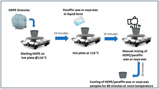
Figure 1.
Schematic of preparation of HDPE/paraffin wax and soya wax samples.
Table 2.
Composition HDPE/paraffin wax and soya wax samples.
2.2. Preparation of Shape-Stable Composite PCM
The HDPE(60)/PW(40) and HDPE(65)/SW(35) were selected as SSPCM and were used to synthesize SSCPCM. SSCPCM were prepared by loading additives, namely, multi-walled carbon nanotubes (MWCNTs) and graphene nanoparticles (GNPs). These additives were loaded in varying percentages, as shown in Table 3. Initially, PW was melted on a hot plate at constant temperature of 70 °C for 15 min. MWCNT weighing 1 wt% of PW was added to the liquid PW. Hot plate magnetic stirring at constant temperature of 70 °C and at 800 RPM for 60 min was conducted. After this, ultrasonication of PW/MWCNT at 70 °C and at 20 kHz for 90 min was conducted so that MWCNT particles were homogeneously dispersed in PW. After ultrasonication, PW/MWCNT sample was allowed to cool at room temperature for 30 min. A total of 40 wt% of PW/MWCNT was then mixed in 60 wt% of HDPE. The mixing was performed on a hot plate that was maintained at constant temperature of 110 °C. The sample was then cooled at room temperature for 60 min. Finally, the HDPE (60)/PW(39)/MWCNT(1) sample was prepared and named SSCPCM/PW/M1, as presented in Table 2. Similarly, all other samples, i.e., SSCPCM/PW/M2, SSCPCM/PW/M3, SSCPCM/PW/G1, SSCPCM/PW/G2, SSCPCM/PW/G3, SSCPCM/SW/M1, SSCPCM/SW/M2, SSCPCM/SW/M3, SSCPCM/SW/G1, SSCPCM/SW/G2, and SSCPCM/SW/G3, were also prepared by following the same procedure. The schematic of procedure of preparation of SSCPCMs is depicted in Figure 2.
Table 3.
Composition of SSCPCM samples.
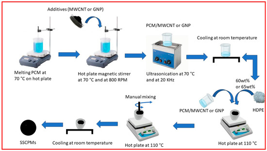
Figure 2.
Schematic of preparation of SSCPCM samples.
3. Results
3.1. Leakage Test
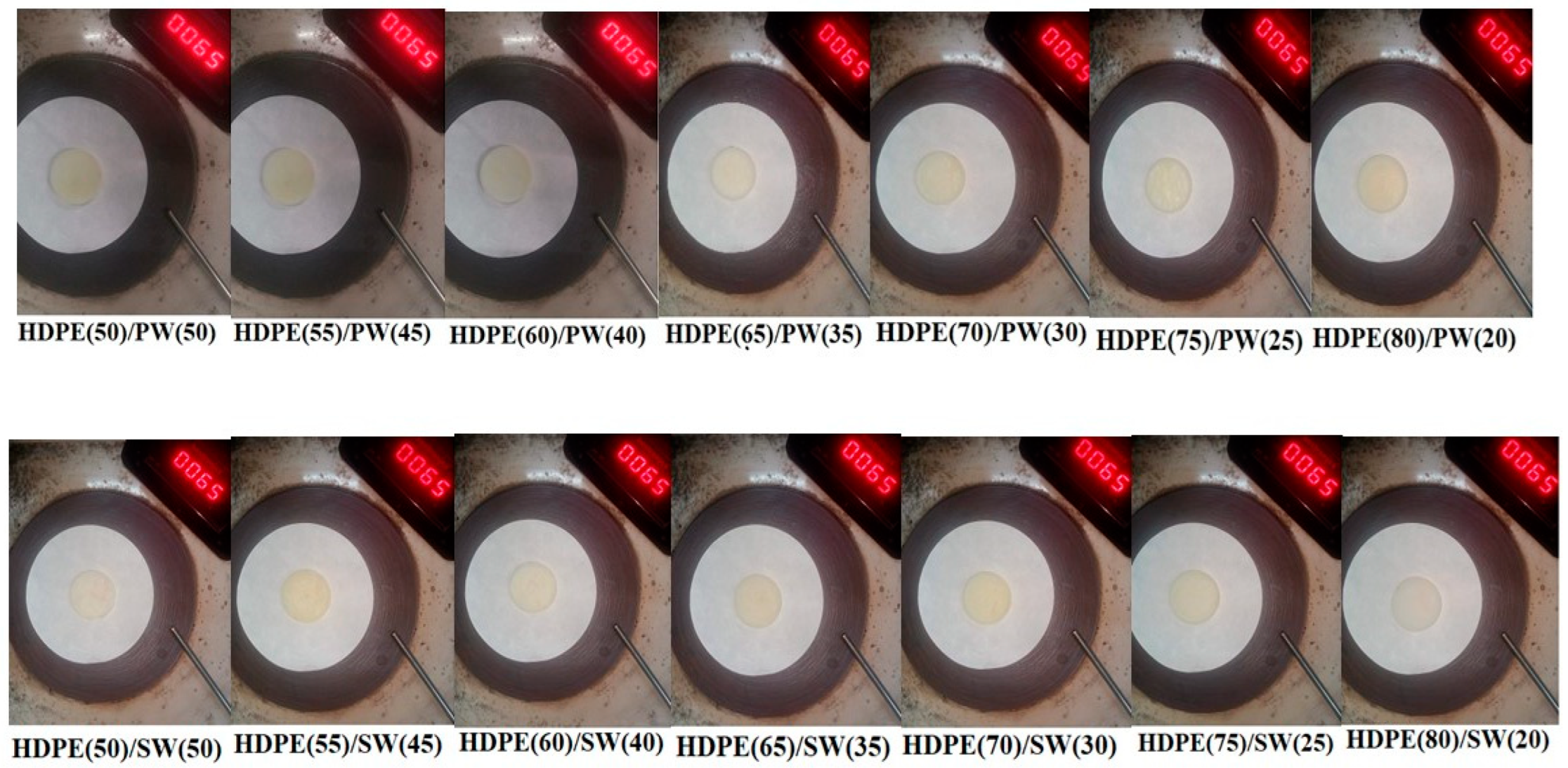
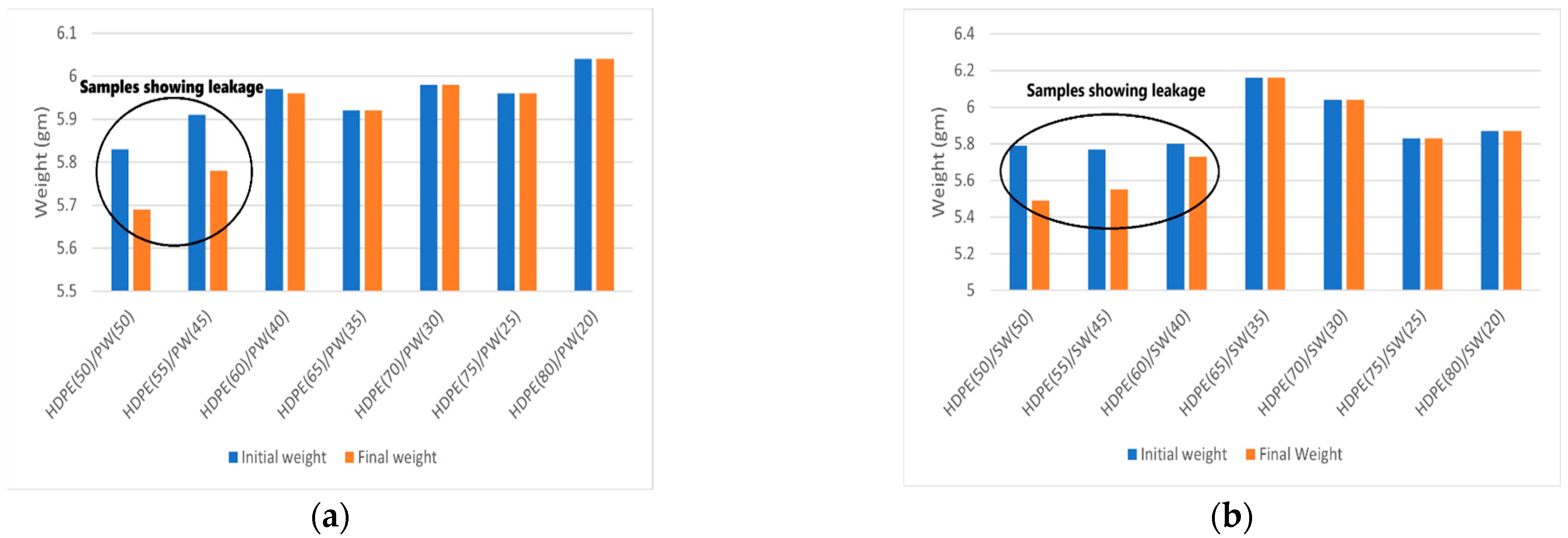
The leakage test of all the samples is shown in Figure 3, and the corresponding weight loss is presented in Figure 4a,b. It can be seen that HDPE(50)/PW(50) and HDPE(55)/PW(45) show weight loss due to leakage of PCM among paraffin wax-loaded samples. No other paraffin wax-loaded samples showed any weight loss, which suggests that HDPE provides sufficient skeleton support to liquid PCM. The maximum loading of paraffin wax observed was 40 wt% in HDPE without any leakage. Therefore, the HDPE (60)/PW(40) sample was selected as ss-PCM-loaded with PW. Similarly, the HDPE(65)/SW(35) sample was selected as ss-PCM with a maximum 35 wt% of SW loading without any leakage.
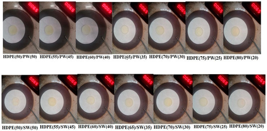
Figure 3.
Leakage test performance of SSPCMs.
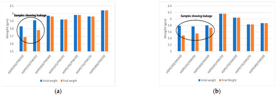
Figure 4.
Weight loss representation of SSPCMs before and after heating for (a) HDPE/PW samples (b) HDPE/SW samples.
3.2. Heating and Cooling Profile
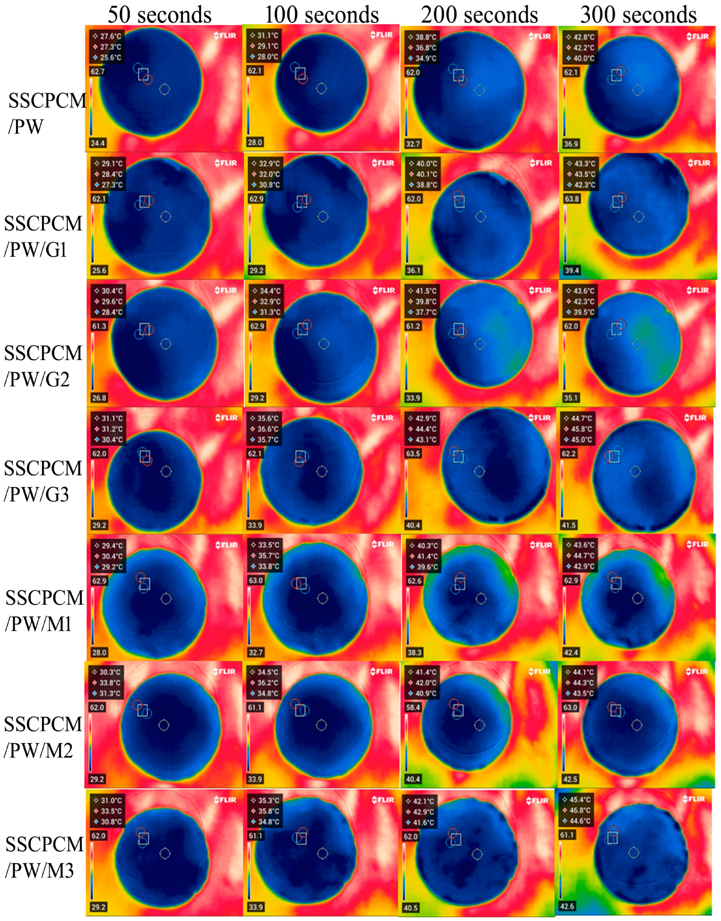
The heating profiles of all SSCPCMs are analyzed using infrared thermal images. Initially, the samples were at room temperature and were placed one-by-one over a hot plate, which was maintained at a constant temperature of 65 °C. The thermal images were taken at time intervals of 50 s, 100 s, 200 s, and 300 s, as shown in Figure 5 and Figure 6. A rise in temperature with respect to time was observed in every sample. The rise in temperature trend was also observed as the mass fraction of the MWCNT, and the GNP increased. Thus, for every sample, the maximum surface temperature was obtained at 300 s and at 3 wt% loading of MWCNT and GNP, respectively. The maximum temperature of SSCPCM/PW/G and SSCPCM/PW/M was observed in SSCPCM/PW/G3 and SSCPCM/PW/M3 at 44.3 °C and 44.8 °C, respectively, at 300 s. Similarly, the maximum temperature of SSCPCM/SW/G and SSCPCM/SW/M was observed in SSCPCM/SW/G3 and SSCPCM/SW/M3 at 44.7 °C and 45.4 °C, respectively, at 300 s. The temperature profile of each sample was greatly affected by the concentration of nanoparticles. It is easily visible that the sample containing a higher concentration of nanoparticles heated faster in comparison with other samples. SSCPCM/PW and SSCPCM/SW show the smallest rise in temperature. This is because of the absence of nanoparticles, resulting in lower thermal conductivity of the samples. The heating rate of samples improves as the wt% of nano-additives increases.
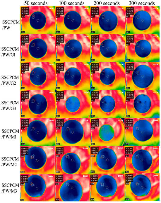
Figure 5.
Surface temperature profile of SSCPCM/PW, SSCPCM/PW/G, and SSCPCM/PW/M samples.
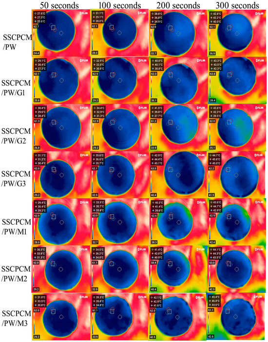
Figure 6.
Surface temperature profile of SSCPCM/SW, SSCPCM/SW/G, and SSCPCM/SW/M samples.
3.3. Steady-State Thermal Performance
The temperature profile of all SSCPM samples was analyzed with respect to time at a constant temperature. This helps in understanding the steady-state temperature profile of SSCPCMs. The samples were placed on a hot plate at a constant temperature of 60 °C. The heat at 60 °C was supplied for 30 min, and after this, the samples were allowed to cool for 30 min at room temperature.
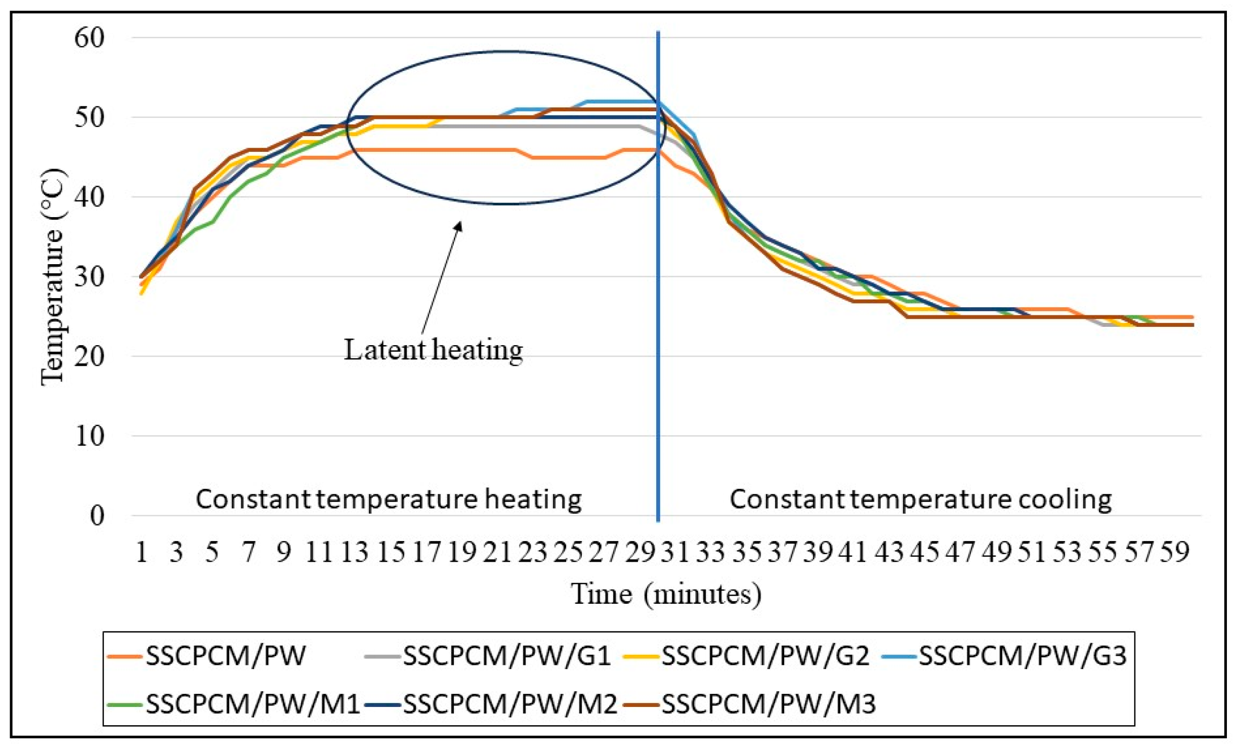
The heating and cooling profiles of PW-loaded and SW-loaded SSCPCMs are depicted in Figure 7 and Figure 8. The heating and cooling trend of all the SSCPCMs is almost similar. However, due to variations in additive loading, the magnitude of heating and cooling of each sample differs. Among PW-loaded samples, SSCPCM/PW/G3 reached the highest temperature at 52 °C, followed by 51 °C by SSCPCM/PW/M3, in 30 min. The cooling rate of these two samples is the fastest among all the PW-loaded samples. This can be attributed to the fact that the loading of nanoparticle additives enhances the heat transfer rate, causing faster charging and discharging. Similarly, among all SW-loaded samples, SSCPCM/SW/G3 and SSCPCM/SW/M3 reached the highest temperature mark at 50 °C in the shortest time. All samples show a linear increase in the rise in temperature with respect to time until the phase transformation of PCM starts. This rise in temperature is faster in samples having high loading of nano-additives. As soon as the phase transformation of PCM starts in SSCPCM, there is no change in temperature observed. A similar trend is visible in the cooling curve of SSCPCMs.
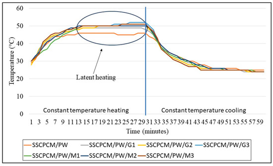
Figure 7.
Heating and cooling temperature profile of paraffin wax-loaded SSCPCMs.
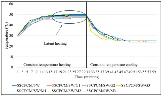
Figure 8.
Heating and cooling temperature profile of soya wax-loaded SSCPCMs.
3.4. Thermal Energy Storage
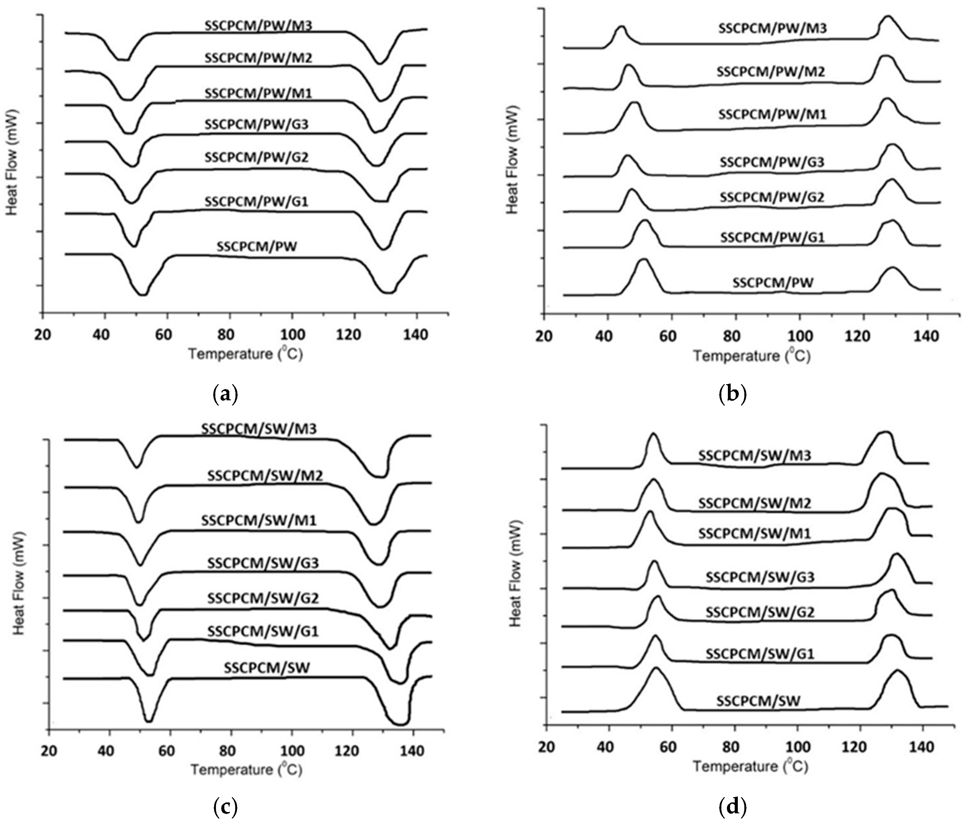
Thermal energy storage parameters, such as melting point, freezing point, melting enthalpy, and freezing enthalpy, are obtained using DSC. All the SSCPCM samples underwent DSC under similar conditions. The DSC thermographs of SSCPCM/PW and SSCCPCM/SW loaded with nanoparticles are presented in Figure 9a and Figure 9b, respectively. The trend of DSC is almost similar for all the samples. The melting point, freezing point, melting enthalpy, and freezing enthalpy of SSCPCMs are presented in Table 4. The melting enthalpy and freezing enthalpy of SSCPCM/PW and SSCPCM/SW are 93.5 J/g and 86.8 J/g, respectively. Adding nano-additives in SSCPCM reduces the enthalpy of SSCPCM. This reduction can be correlated with the reduction in wt% of PW and SW in SSCPCM. However, the reduction in enthalpy of SSCPCM is not significant, and it has a substantially good thermal energy storage capacity. The higher the percentage of additives, the less the enthalpy of SSCPCM in comparison with SSCPCM/PW and SSCPCM/SW. It has also been observed that there is variation in the melting point and freezing point of all the SSCPCM samples. The melting of SSCPCM/PW/G1, SSCPCM/PW/G2, SSCPCM/PW/G3, SSCPCM/PW/M1, SSCPCM/PW/M2, SSCPCM/PW/M3, SSCPCM/SW/G1, SSCPCM/SW/G2, SSCPCM/SW/G3, SSCPCM/SW/M1, SSCPCM/SW/M2, and SSCPCM/SW/M3 is earlier than SSCPCM/PW and SSCPCM/SW. This can be correlated with the fact that loading nano-additives will enhance the heat transfer rate, causing faster melting.
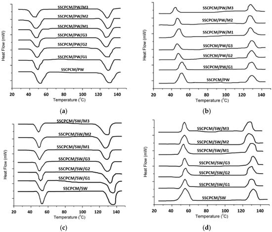
Figure 9.
DSC thermographs of (a) endotherm of SSCPCM/PW samples; (b) exotherm of SSCPCM/PW samples; (c) endotherm of SSCPCM/SW samples; and (d) exotherm of SSCPCM/SW samples.
Table 4.
Thermal energy storage parameters of SSCPCM samples.
3.5. Thermal Stability
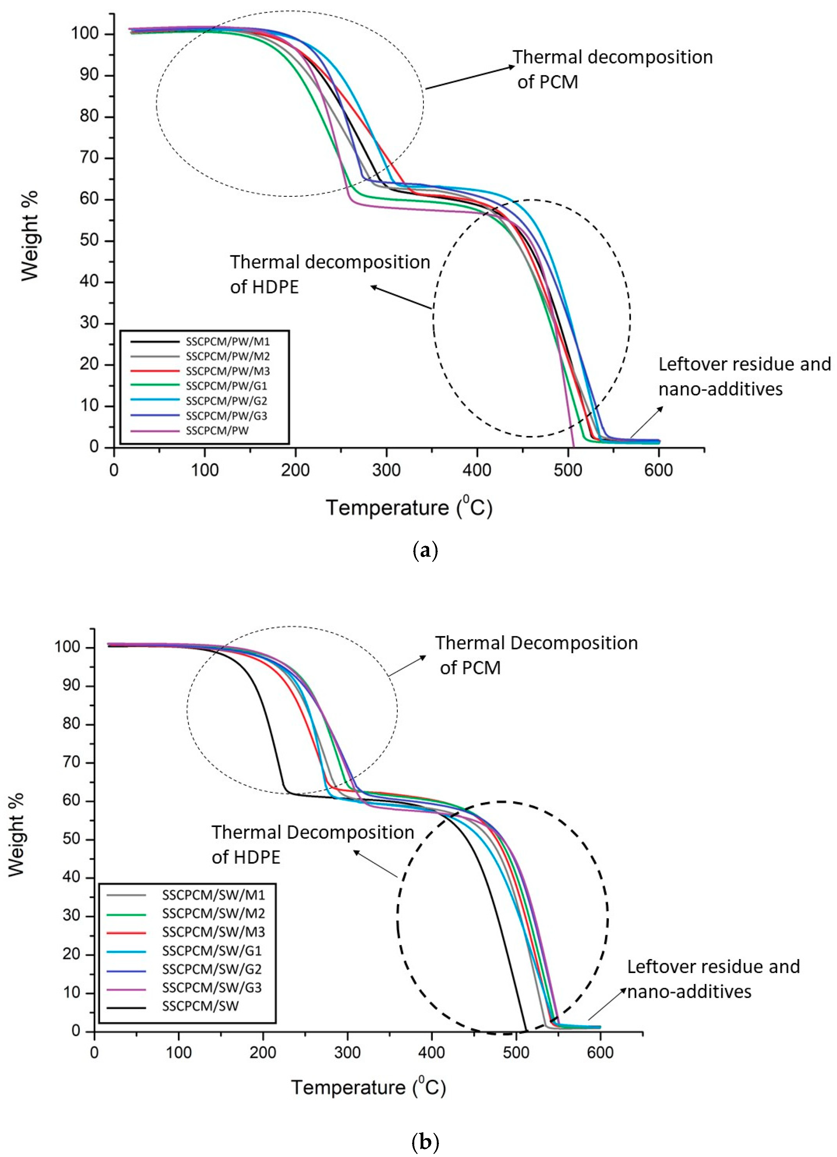
Thermal stability is the ability of a material to remain stable at elevated temperatures. To evaluate it, thermogravimetric analysis (TGA) of all the SSCPCM samples was conducted. TGA is conducted between the temperature range of room temperature and 600 °C at a heating rate of 5 °C/min. It was conducted in a nitrogen atmosphere at a purge rate of 20 mL/minute. The TGA thermographs of SSCPCM/PW and SSCPCM/SW samples are shown in Figure 10. For a better understanding of the thermal decomposition of the samples, TGA thermographs can be divided into four steps. In step one, the samples are heated from room temperature to 150 °C. In this step, only the phase transition of the PCM occurs, and an almost negligible weight loss occurs. Also, in this step, only volatile impurities are decomposed. In step two, weight loss of PCM occurs between the temperature range of 150 °C and 300 °C. The PCM present in the composite samples completely decomposes, and the sample is left with HDPE and nano-additives. In step three, the temperature further increases from 300 °C to 450 °C. In this step, no significant weight loss was observed among all the samples. HDPE completely liquifies in this temperature range. In step four, upon further rising temperature, HDPE starts decomposing. It completely decomposes at 550 °C. After 550 °C, only the nano-additives and carbon residue of the composite are left in the pan of TGA. These results suggest that the SSCPCM is completely stable up to 150 °C and can be used as a TES material for the applications where temperature range is up to 150 °C. It seems that the trend of TGA thermographs for SSCPCM loaded with PW and graphene nanoparticles and SSCPCM loaded with SW and MWCNT nanoparticles are the same. In both cases, major weight loss occurs due to the decomposition of PCM and HDPE. Above 500 °C, only the carbon residue of HDPE and PCM along with nano-additives are left. No decomposition of graphene nanoparticles and MWCNT was observed. SSCPCM/PW and SSCPCM/SW samples show 100% weight loss above 500 °C.
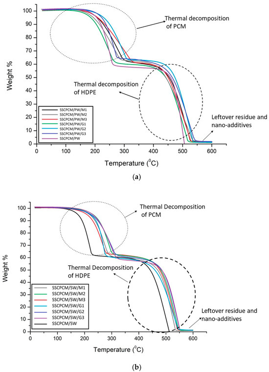
Figure 10.
TGA thermographs of (a) SSCPCM/PW and (b) SSCPCM/SW samples.
3.6. Thermal Conductivity
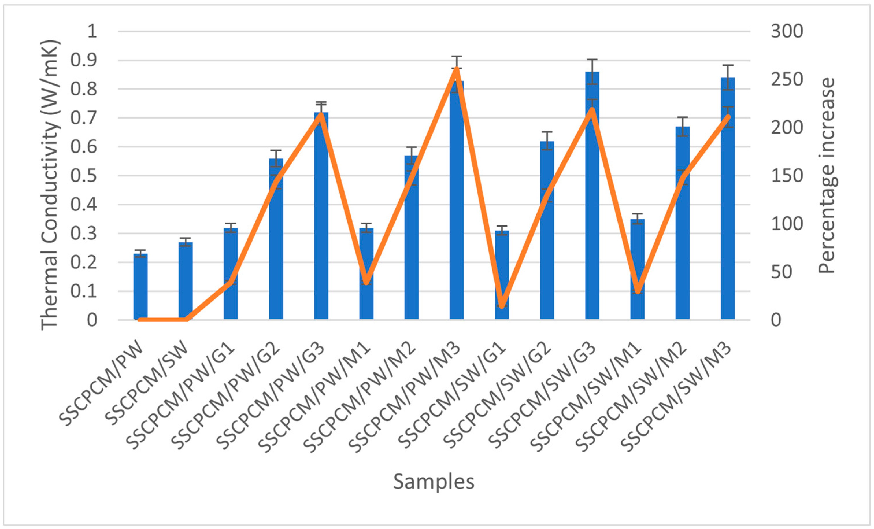
Thermal conductivity is how quickly a material transfers heat. The thermal conductivity of all SSCPCM samples was measured using the TPS (Transient Plane Source) technique. In this method, a spiral-shaped sensor made of nickel sandwiched between two layers of Kapton is kept in contact with the measuring material. The thickness of the nickel was 10 µm and the thickness of Kapton was 25 µm. The sensor was clamped between two samples of the same material and heat was supplied to the sensor. Consequently, the temperature rises and can be recorded. Changes in temperature with respect to time and heat made it possible to calculate the thermal conductivity of the samples. Each sample underwent a thermal conductivity test three consecutive times. This was performed to ensure repeatability and minimize the chances of errors in the readings. The average of three readings was taken as the value of thermal conductivity. In general, PCMs have low thermal conductivity, resulting in poor charging and discharging of heat. Consequently, they reduce the heat transfer rate, resulting in poor utilization of latent heat storage of the PCM. This limitation can be overcome by loading high thermal conductivity nanoparticles into PCMs [24]. In this study, MWCNT and GO were used as nano-additives. These nanoparticles have a high specific surface area and three-dimensional structure, which improves the heat transfer rate without altering the chemical composition of the PCM [11]. The thermal conductivity value of each sample was investigated experimentally. The thermal conductivity of each SSCPCM sample is presented in Figure 11. It can be seen that a rising trend in thermal conductivity is visible as nano-additive content increases. There are thermal conductivity values of 0.23 W/mK, 0.27 W/mK, 0.32 W/mK, 0.56 W/mK, 0.72 W/mK, 0.32 W/mK, 0.57 W/mK, 0.83 W/mK, 0.31 W/mK, 0.62 W/mK, 0.86 W/mK, 0.35 W/mK, 0.67 W/mK, and 0.84 W/mK for SSCPCM/SW, SSCPCM/PW, SSCPCM/PW/G1, SSCPCM/PW/G2, SSCPCM/PW/G3, SSCPCM/PW/M1, SSCPCM/PW/M2, SSCPCM/PW/M3, SSCPCM/SW/G1, SSCPCM/SW/G2, SSCPCM/SW/G3, SSCPCM/SW/M1, SSCPCM/SW/M2, and SSCPCM/SW/M3, respectively. Rises in thermal conductivity of 39.1%, 143.4%, 213.0%, 39.1%, 147.8%, and 260.8% were observed in SSCPCM/PW/G1, SSCPCM/PW/G2, SSCPCM/PW/G3, SSCPCM/PW/M1, SSCPCM/PW/M2, and SSCPCM/PW/M3 in comparison with SSCPCM/PW, respectively. Percentage rises in thermal conductivity of 14.8%, 129.6%, 218.5%, 29.6%, 148.1%, and 211.1% were observed in SSCPCM/SW/G1, SSCPCM/SW/G2, SSCPCM/SW/G3, SSCPCM/SW/M1, SSCPCM/SW/M2, and SSCPCM/SW/M3 in comparison with SSCPCM/SW, respectively.
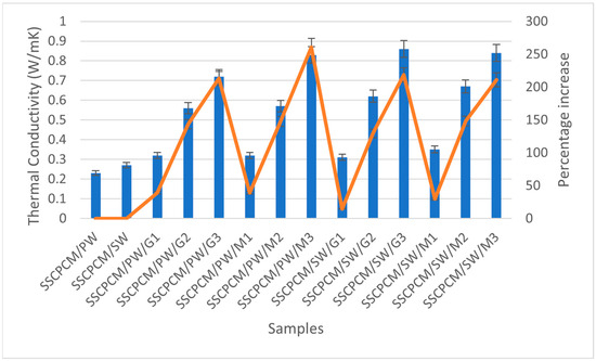
Figure 11.
Thermal conductivity (represented by blue bars) and corresponding percentage increase (represented by orange line) in comparison with SSCPCM/PW and SSCPCM/SW of all the SSCPCM samples.
4. Recommendation for Future Work
The extension of this study may include further thermo–physical analysis to access the potential capabilities that can be candidates for thermal energy storage. Thermal reliability is an important parameter that can be investigated to evaluate TES properties after heating and cooling cycles. It helps in identifying the ability of SSCPM samples to work for a longer duration. In addition, chemical and physical analysis can also be conducted to evaluate the physical and chemical stability of the composite. Furthermore, morphological analysis is also helpful in understanding the surface structure of the SSCPCM.
5. Conclusions
In this study, SSCPCM samples using paraffin wax and soya wax as PCMs, supported with HDPE and loaded with graphene oxide and MWCNT, were prepared. It was observed that a maximum 40 wt% and 35 wt% of paraffin wax and soya wax, respectively, are supported by HDPE without any leakage at elevated temperatures. The heating rate and cooling rate of SSCPCM samples increase with an increase in wt% of nano-additives. The fastest heating and cooling behavior with respect to time is shown by SSCPCM/PW/M3, SSCPCM/PW/G3, SSCPCM/SW/M3, and SSCPCM/SW/G3 among all SSCPCMs. A maximum rise in temperature of 45.4 °C is observed in SSCPCM/SW/G3 after heating for 300 s in comparison with other SSCPCMs. A maximum rise in thermal conductivity of 260.8% and 218.5% is shown by SSCPCM/PW/M3 and SSCPCM/SW/G3 in comparison with SSCPCM/PW and SSCPCM/SW, respectively. However, a maximum thermal conductivity of 0.86 W/mK and 0.84 W/mk is shown by SSCPCM/SW/G3 and SSCPCM/SW/M2. There is no significant change in the TES parameters of SSCPCM. However, there is a reduction in melting enthalpy and almost negligible deviation in the melting and freezing points of SSCPCM. The loss in enthalpy is not significant and thus it can be used for a variety of TES applications. Furthermore, SSCPCM is thermally stable at elevated temperatures and can easily withstand 150 °C temperature without losing its TES properties.
Author Contributions
Data curation, D.K.Y. and R.K.S.; Formal analysis, A.K.G., R.K.S. and B.S.S.; Funding acquisition, D.K.Y. and B.S.S.; Investigation, P.K.S.R.; Methodology, P.K.S.R.; Project administration, A.K.G. and B.S.S.; Resources, D.K.Y.; Visualization, R.K.S.; Writing—original draft, P.K.S.R.; writing—review and editing, A.K.G. and B.S.S. All authors have read and agreed to the published version of the manuscript.
Funding
This research received no external funding.
Data Availability Statement
Data are unavailable due to privacy or ethical restrictions.
Acknowledgments
Science and Engineering Research Board (SERB), Government of India (Project number CRG/2021/005669) is acknowledged for the use of equipment in this project to carry out this current study.
Conflicts of Interest
The authors declare no conflict of interest.
Nomenclature
| TES | Thermal Energy Storage |
| PCM | Phase Change Material |
| SSPCM | Shape Stabilized Phase Change Material |
| SSCPCM | Shape Stabilized Composite Phase Change Material |
| HDPE | High-Density Polyethylene |
| MWCNT | multi-walled carbon nanotube |
| GO | Graphene oxide |
| PW | Paraffin wax |
| SW | Soya wax |
| DSC | Differential scanning calorimetry |
| TGA | Thermogravimetric analysis |
References
- Zhu, C.; Hao, Y.; Wu, H.; Chen, M.; Quan, B.; Liu, S.; Hu, X.; Liu, S.; Ji, Q.; Lu, X.; et al. Self-Assembly of Binderless MXene Aerogel for Multiple-Scenario and Responsive Phase Change Composites with Ultrahigh Thermal Energy Storage Density and Exceptional Electromagnetic Interference Shielding. Nanomicro Lett. 2024, 16, 57. [Google Scholar] [CrossRef] [PubMed]
- Khan, M.M.; Alkhedher, M.; Ramadan, M.; Ghazal, M. Hybrid PCM-based thermal management for lithium-ion batteries: Trends and challenges. J. Energy Storage 2023, 73, 108775. [Google Scholar] [CrossRef]
- Al-Yasiri, Q.; Szabó, M. Energetic and thermal comfort assessment of phase change material passively incorporated building envelope in severe hot Climate: An experimental study. Appl. Energy 2022, 314, 118957. [Google Scholar] [CrossRef]
- Patel, B.; Rathore, P.K.S.; Gupta, N.K.; Sikarwar, B.S.; Sharma, R.K.; Kumar, R.; Pandey, A.K. Location optimization of phase change material for thermal energy storage in concrete block for development of energy efficient buildings. Renew Energy 2023, 218, 119306. [Google Scholar] [CrossRef]
- Balasundaram, P.; Baranidharan, B.; Sivaram, N.M. A VIKOR based selection of phase change material for thermal energy storage in solar dryer system. Mater. Today Proc. 2023, 90, 245–249. [Google Scholar] [CrossRef]
- Yang, X.; Sun, L.; Yuan, Y.; Zhao, X.; Cao, X. Experimental investigation on performance comparison of PV/T-PCM system and PV/T system. Renew Energy 2018, 119, 152–159. [Google Scholar] [CrossRef]
- Iqbal, K.; Khan, A.; Sun, D.; Ashraf, M.; Rehman, A.; Safdar, F.; Basit, A.; Maqsood, H.S. Phase change materials, their synthesis and application in textiles—A review. J. Text. Inst. 2019, 110, 625–638. [Google Scholar] [CrossRef]
- Calati, M.; Hooman, K.; Mancin, S. Thermal storage based on phase change materials (PCMs) for refrigerated transport and distribution applications along the cold chain: A review. Int. J. Thermofluids 2022, 16, 100224. [Google Scholar] [CrossRef]
- Mert, M.S.; Mert, H.H.; Arıcı, M. Development and properties of n-octadecane/kaolinite composites as form-stabilized phase change materials for energy storage. J. Clean. Prod. 2023, 410, 137304. [Google Scholar] [CrossRef]
- Gupta, K.K.; Rathore, P.K.S.; Sikarwar, B.S.; Pandey, A.K. Solar to thermal energy storage performance of composite phase change material supported by copper foam loaded with graphite and boron nitride. Sol. Energy 2024, 272, 112459. [Google Scholar] [CrossRef]
- Cheng, P.; Chen, X.; Gao, H.; Zhang, X.; Tang, Z.; Li, A.; Wang, G. Different dimensional nanoadditives for thermal conductivity enhancement of phase change materials: Fundamentals and applications. Nano Energy 2021, 85, 105948. [Google Scholar] [CrossRef]
- Rathore, P.K.S.; Gupta, K.K.; Patel, B.; Sharma, R.K.; Gupta, N.K. Beeswax as a potential replacement of paraffin wax as shape stabilized solar thermal energy storage material: An experimental study. J. Energy Storage 2023, 68, 107714. [Google Scholar] [CrossRef]
- Zhang, H.; Wang, L.; Xi, S.; Xie, H.; Yu, W. 3D porous copper foam-based shape-stabilized composite phase change materials for high photothermal conversion, thermal conductivity and storage. Renew Energy 2021, 175, 307–317. [Google Scholar] [CrossRef]
- Xiao, X.; Zhang, P.; Li, M. Preparation and thermal characterization of paraffin/metal foam composite phase change material. Appl. Energy 2013, 112, 1357–1366. [Google Scholar] [CrossRef]
- Yao, C.; Kong, X.; Li, Y.; Du, Y.; Qi, C. Numerical and experimental research of cold storage for a novel expanded perlite-based shape-stabilized phase change material wallboard used in building. Energy Convers Manag. 2018, 155, 20–31. [Google Scholar] [CrossRef]
- Huo, Y.; Yan, T.; Chang, X.; Pan, W. Expanded graphite@octadecanol composite phase change material with photothermal conversion interface. Solar Energy 2023, 263, 111922. [Google Scholar] [CrossRef]
- Zauner, C.; Hengstberger, F.; Etzel, M.; Lager, D.; Hofmann, R.; Walter, H. Experimental characterization and simulation of a fin-tube latent heat storage using high density polyethylene as PCM. Appl. Energy 2016, 179, 237–246. [Google Scholar] [CrossRef]
- Tang, Y.; Su, D.; Huang, X.; Alva, G.; Liu, L.; Fang, G. Synthesis and thermal properties of the MA/HDPE composites with nano-additives as form-stable PCM with improved thermal conductivity. Appl. Energy 2016, 180, 116–129. [Google Scholar] [CrossRef]
- Qu, Y.; Wang, S.; Tian, Y.; Zhou, D. Comprehensive evaluation of Paraffin-HDPE shape stabilized PCM with hybrid carbon nano-additives. Appl. Therm. Eng. 2019, 163, 114404. [Google Scholar] [CrossRef]
- Cheng, W.; Zhang, R.; Xie, K.; Liu, N.; Wang, J. Heat conduction enhanced shape-stabilized paraffin/HDPE composite PCMs by graphite addition: Preparation and thermal properties. Sol. Energy Mater. Sol. Cells 2010, 94, 1636–1642. [Google Scholar] [CrossRef]
- Wang, H.; Rao, Z.; Li, L.; Liao, S. A novel composite phase change material of high-density polyethylene/d-mannitol/expanded graphite for medium-temperature thermal energy storage: Characterization and thermal properties. J. Energy Storage 2023, 60, 106603. [Google Scholar] [CrossRef]
- Chen, Y.; Zhang, H.; Xu, C.; Cong, R.; Fang, G. Thermal properties of 1-hexadecanol/high density polyethylene/graphene nanoplates composites as form-stable heat storage materials. Sol. Energy Mater. Sol. Cells 2022, 237, 111580. [Google Scholar] [CrossRef]
- Xie, Y.; Yang, Y.; Liu, Y.; Wang, S.; Guo, X.; Wang, H.; Cao, D. Paraffin/polyethylene/graphite composite phase change materials with enhanced thermal conductivity and leakage-proof. Adv. Compos. Hybrid Mater. 2021, 4, 543–551. [Google Scholar] [CrossRef]
- Wu, S.; Yan, T.; Kuai, Z.; Pan, W. Thermal conductivity enhancement on phase change materials for thermal energy storage: A review. Energy Storage Mater. 2020, 25, 251–295. [Google Scholar] [CrossRef]


Disclaimer/Publisher’s Note: The statements, opinions and data contained in all publications are solely those of the individual author(s) and contributor(s) and not of MDPI and/or the editor(s). MDPI and/or the editor(s) disclaim responsibility for any injury to people or property resulting from any ideas, methods, instructions or products referred to in the content. |
© 2024 by the authors. Licensee MDPI, Basel, Switzerland. This article is an open access article distributed under the terms and conditions of the Creative Commons Attribution (CC BY) license (https://creativecommons.org/licenses/by/4.0/).