
Energy Analysis of Waste Heat Recovery Using Supercritical CO2 Brayton Cycle for Series Hybrid Electric Vehicles


 , and
, and 
Abstract
1. Introduction
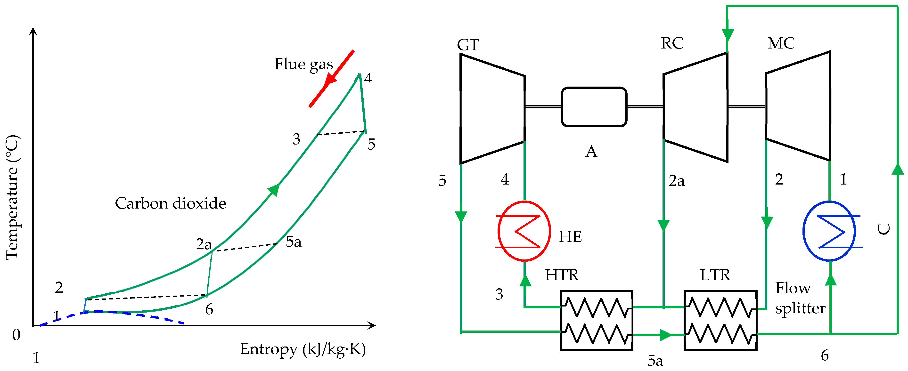
2. System Analysis
3. Thermodynamic Model
3.1. Model Validation
3.2. Simulation of Split-Flow sCO2 Recompression Brayton Cycle Applied to an Internal Combustion Engine of a Serial Diesel-Electric Hybrid Bus
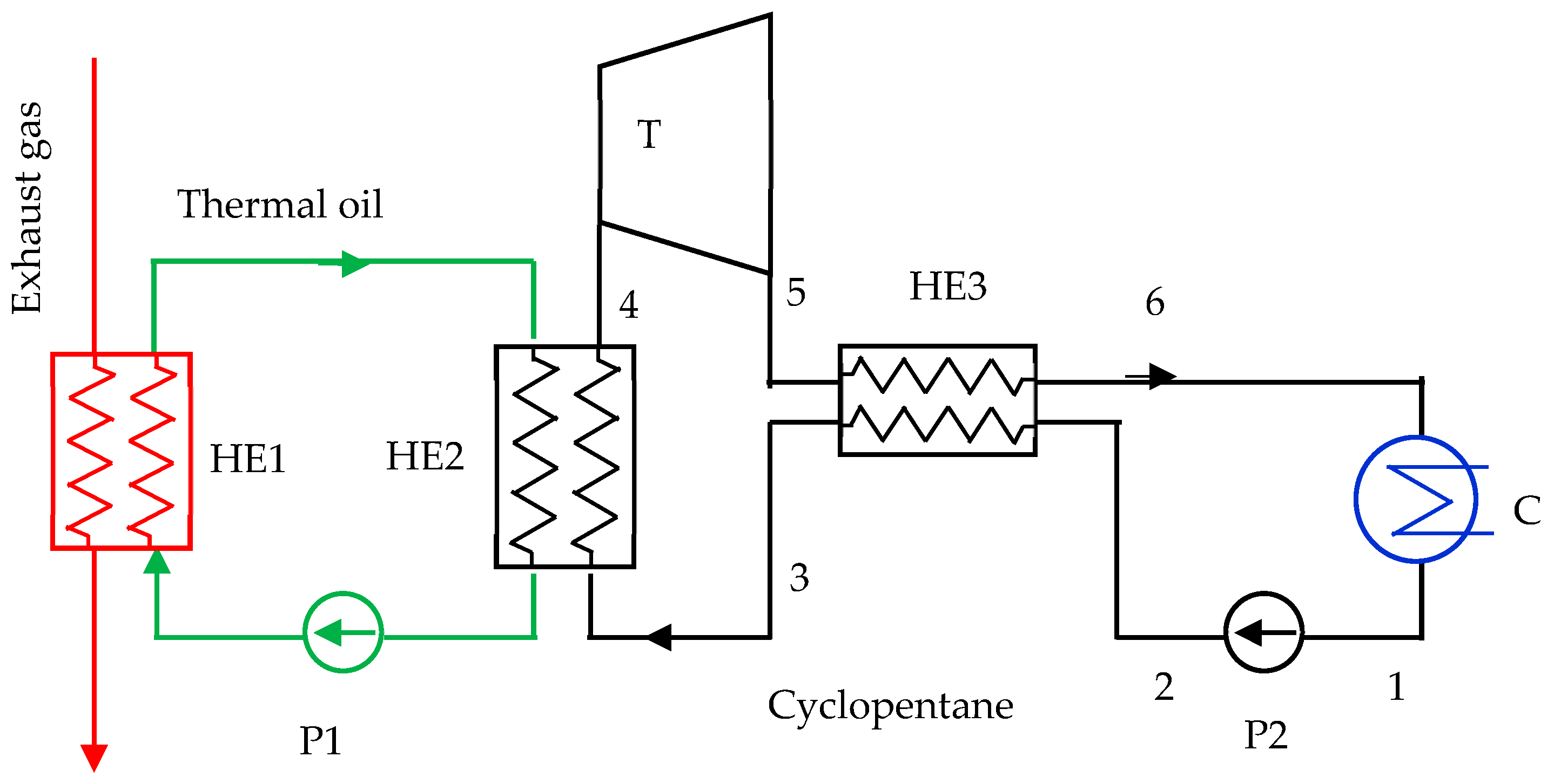
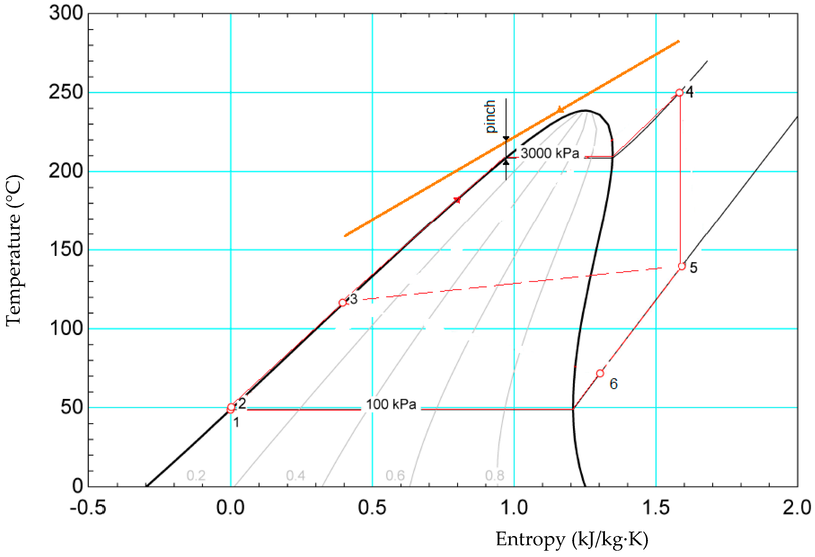
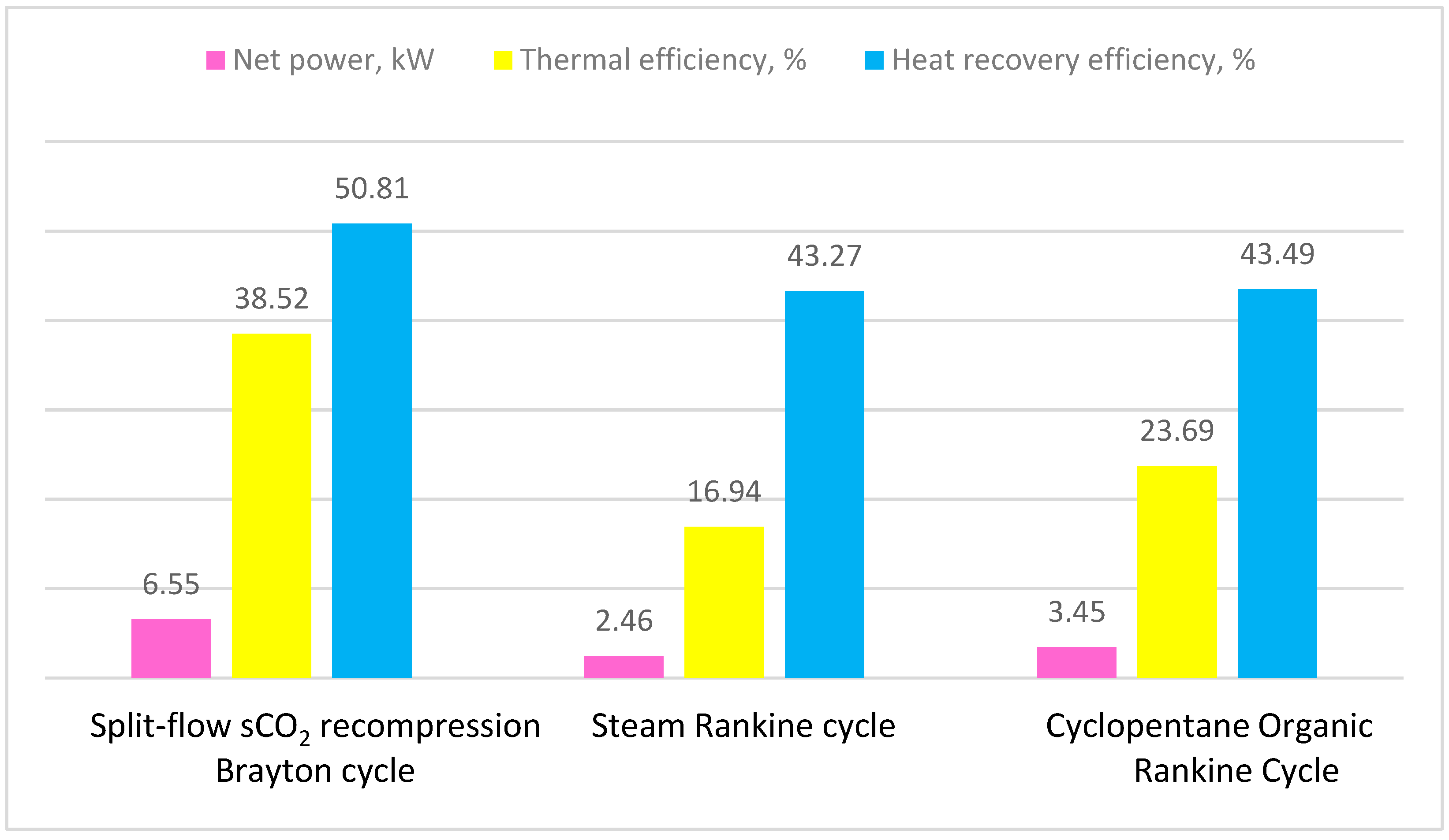
4. Performance Comparison of Split-Flow sCO2 Recompression Brayton Cycle with Other Cycles
5. Conclusions
Author Contributions
Funding
Data Availability Statement
Conflicts of Interest
Nomenclature
| Abbreviations or Symbol | |
| A | heat transfer surface area, m2; |
| cp | specific heat, kJ/(kg·K); |
| d | diameter, m; |
| h | enthalpy, kJ/kg |
| hl | latent heat of water vapor, kJ/kg |
| k | thermal conductivity, W/(m·K) |
| L | length, m |
| m | mass, kg |
| SR | flow split ratio |
| t | temperature, °C |
| T | temperature, K |
| U | overall heat transfer coefficient, W/(m2·K) |
| v | velocity, m/s |
| α | heat transfer coefficient, W/(m2·K) |
| δ | thickness, mm |
| ε | effectiveness |
| λ | thermal conductivity, W/(m·K) |
| η | efficiency |
| μ | dynamic viscosity, kg/(m·s). |
| ρ | density, kg/m3; |
| mass flow rate, kg/s | |
| power, kW | |
| Subscripts | |
| CO2 | carbon dioxide |
| env | environmental |
| exh | exhaust gas |
| f | fluid |
| GT | gas turbine |
| H2O | water |
| HR | heat recovery |
| HTR | higher temperature recuperator |
| i | inlet or inner |
| LTR | lower temperature recuperator |
| MC | main compressor |
| N2 | nitrogen |
| o | outlet/outer |
| O2 | oxygen |
| RC | recompressor |
| t | thermal or tube |
| w | cooling water |
References
- European Environment Agency. Available online: https://www.eea.europa.eu/en (accessed on 10 January 2024).
- Heber, L.; Schwab, J.; Knobelspies, T. 3 kW Thermoelectric Generator for Natural Gas-Powered Heavy-Duty Vehicles—Holistic Development, Optimization and Validation. Energies 2022, 15, 15. [Google Scholar] [CrossRef]
- Bou Nader, W.; Chamoun, J.; Dumand, C. Thermoacoustic engine as waste heat recovery system on extended range hybrid electric vehicles. Energy Convers. Manag. 2020, 215, 112912. [Google Scholar] [CrossRef]
- Aghaali, H.; Ångstrom, H.-E. A review of turbocompounding as a waste heat recovery system for internal combustion engines. Renew. Sustain. Energy Rev. 2015, 49, 813–824. [Google Scholar] [CrossRef]
- Freymann, R.; Ringler, J.; Seifert, M.; Horst, T. The second generation turbosteamer. MTZ Worldw. 2012, 73, 18–23. [Google Scholar] [CrossRef]
- Jelmer, R.; Olof, E.; Sven, B.A.; Karin, M. Exhaust waste heat recovery from a heavy-duty truck engine: Experiments and simulations. Energy 2022, 238 Pt B, 121698. [Google Scholar]
- Güven, M.; Bedir, H.; Anlas, G. Optimization and application of Stirling engine for waste heat recovery from a heavy-duty truck engine. Energy Convers. Manag. 2019, 180, 411–424. [Google Scholar] [CrossRef]
- Galindo, J.; Serrano, J.; Dolz, V.; Kleut, P. Brayton cycle for internal combustion engine exhaust gas waste heat recovery. Adv. Mech. Eng. 2015, 7, 1687814015590314. [Google Scholar] [CrossRef]
- Shi, L.; Shu, G.; Tian, H.; Chang, L.; Huang, G.; Chen, T. Experimental investigations on a CO2-based Transcritical Power Cycle (CTPC) for waste heat recovery of Diesel engine. Energy Procedia 2017, 129, 955–962. [Google Scholar] [CrossRef]
- Johnson, V. Heat-Generated Cooling Opportunities in Vehicles; SAE Technical Paper 2002-01-1969; SAE International: Warrendale, PA, USA, 2022. [Google Scholar] [CrossRef]
- Gequn, S.; Mingru, Z.; Hua, T.; Haiqiao, W.; Xingyu, L.; Yongzhan, H.; Weijie, Z. Experimental investigation on thermal OS/ORC (Oil Storage/Organic Rankine Cycle) system for waste heat recovery from Diesel engine. Energy 2016, 107, 693–706. [Google Scholar]
- Vyacheslav, R.; Timur, A.; Alexander, C.; Anatoly, V. Determination of the required power for bus hybrid engine. E3S Web Conf. 2020, 178, 01076. [Google Scholar] [CrossRef]
- Ruixiao, S.; Yuche, C.; Abhishek, D.; Philip, P. Hybrid electric buses fuel consumption prediction based on real-world driving data. Transp. Res. Part D Transp. Environ. 2021, 91, 102637. [Google Scholar]
- Jung, D.; Park, S.; Min, K. Study on the Application of the Waste Heat Recovery System to Heavy-Duty Series Hybrid Electric Vehicles; SAE Technical Paper 2013-01-1455; SAE International: Warrendale, PA, USA, 2013. [Google Scholar] [CrossRef]
- Arias, D.; Shedd, T.; Jester, R. Theoretical Analysis of Waste Heat Recovery from an Internal Combustion Engine in a HYBRID vehicle; SAE Technical Paper 2006-01-1605; SAE International: Warrendale, PA, USA, 2006. [Google Scholar] [CrossRef]
- Upendra, K.; Grauers, A. Synergy and Conflicts between Waste Heat Recovery System and Hybrid Electric Vehicle; Chalmers University of Technology: Gothenburg, Sweden, 2015. [Google Scholar]
- U.S. Department of Energy. 4R Supercritical Carbon Dioxide Brayton Cycle, Quadrennial Technology Review. 2015. Available online: www.energy.gov (accessed on 27 October 2023).
- Liu, L.; Yang, Q.; Cui, G. Supercritical Carbon Dioxide(s-CO2) Power Cycle for Waste Heat Recovery: A Review from Thermodynamic Perspective. Processes 2020, 8, 1461. [Google Scholar] [CrossRef]
- Rochau, G.E.; Pasch, J.J.; Carlson, M.D.; Fleming, D.D.; Kruizenga, A.M.; Sharpe, R.A.; Wilson, M.C. Supercritical CO2 Brayton Cycles, NP-NE Workshop #2–4 August 2014. Available online: https://www.osti.gov/biblio/1221819 (accessed on 21 March 2023).
- Da, L.; Qiang, S.; Ke, S.; Guodong, Z.; Shuzhan, B.; Guoxiang, L. Diesel engine waste heat recovery system comprehensive optimization based on system and heat exchanger simulation. Open Phys. 2021, 19, 331–340. [Google Scholar]
- Ion, V.I.; Popescu, F. Efficiency Improvement of a Biogas Engine-Driven CHP plant. Sci. Work. Univ. Food Technol. 2016, 63, 255–261. [Google Scholar]
- Wang, T.; Zhang, Y.; Zhang, J.; Peng, Z.; Shu, G. Comparisons of system benefits and thermo-economics for exhaust energy recovery applied on a heavy-duty Diesel engine and a light-duty vehicle gasoline engine. Energy Convers. Manag. 2014, 84, 97–107. [Google Scholar] [CrossRef]
- Dal, C.E.; Lazzaretto, A.; Toffolo, A. A novel extension of the SYNTHSEP methodology for the optimal synthesis and design of supercritical 2 cycles in waste heat recovery applications. Energy Convers. Manag. 2023, 276, 116535. [Google Scholar]
- White, C. Analysis of Brayton Cycles Utilizing Supercritical Carbon Dioxide. United States. 2014. Available online: https://www.osti.gov/biblio/1490264 (accessed on 12 March 2023).
- Seong, J.B.; Minseok, K.; Seong, K.C.; Seungjoon, B.; Jeong, I.L.; Jae, E.C. Review of supercritical CO2 power cycle technology and current status of research and development. Nucl. Eng. Technol. 2015, 47, 647–661. [Google Scholar]
- U.S. Department of Energy. Quadrennial Technology Review 2015, Chapter 4—Advancing Clean Electric Power Technologies. Available online: https://www.energy.gov/quadrennial-technology-review-2015-omnibus (accessed on 20 November 2023).
- Wang, R.; Wang, X.; Bian, X.; Zhang, X.; Cai, J.; Tian, H.; Shu, G.; Wang, M. An optimal split ratio in design and control of a recompression supercritical 2 Brayton system. Energy 2023, 277, 127676. [Google Scholar] [CrossRef]
- Mark, A. Optimization of the Closed Supercritical CO2 Brayton Cycle with the Detailed Simulation of Heat Exchangers; SoftInWay Inc.: Burlington, MA, USA, 2021. [Google Scholar]
- Battista, D.; Cipollone, D.R. Waste Energy Recovery and Valorization in Internal Combustion Engines for Transportation. Energies 2023, 16, 3503. [Google Scholar] [CrossRef]
- Chen, Y.; Lundqvist, P.; Platell, P. Theoretical research of carbon dioxide power cycle application in automobile industry to reduce vehicle’s fuel consumption. Appl. Therm. Eng. 2005, 25, 2041–2053. [Google Scholar] [CrossRef]
- Gequn, S.; Lingfeng, S.; Hua, T.; Xiaoya, L.; Guangdai, H.; Liwen, C. An improved CO2-based transcritical Rankine cycle (CTRC) used for engine waste heat recovery. Appl. Energy 2016, 176, 171–182. [Google Scholar]
- Walnum, H.T.; Neksa, P.; Nord, L.O.; Andresen, T. Modelling and simulation of CO2 (carbon dioxide) bottoming cycles for offshore oil and gas installations at design and off-design conditions. Energy 2013, 59, 513–520. [Google Scholar] [CrossRef]
- Hou, S.; Wu, Y.; Zhou, Y.; Yu, L. Performance analysis of the combined supercritical CO2 recompression and regenerative cycle used in waste heat recovery of marine gas turbine. Energy Convers. Manag. 2017, 151, 73–85. [Google Scholar] [CrossRef]
- Lingfeng, S.; Gequn, S.; Hua, T.; Tianyu, C.; Peng, L.; Ligeng, L. Dynamic tests of CO2-Based waste heat recovery system with preheating process. Energy 2019, 171, 270–283. [Google Scholar] [CrossRef]
- Correa, F.; Barraza, R.; Too, Y.C.S.; Padilla, R.V.; Cardemil, J.M. Optimized operation of recompression sCO2 Brayton cycle based on adjustable recompression fraction under variable conditions. Energy 2021, 227, 120334. [Google Scholar] [CrossRef]
- Yunus, A.Ç.; Boles, M.A. Thermodynamics: An Engineering Approach, 9th ed.; McGraw-Hill Education: New York, NY, USA, 2018. [Google Scholar]
- Bell, I.H.; Wronski, J.; Quoilin, S.; Lemort, V. Pure and Pseudo-pure Fluid Thermophysical Property Evaluation and the Open-Source Thermophysical Property Library CoolProp. Ind. Eng. Chem. Res. 2014, 53, 2498–2508. [Google Scholar] [CrossRef]
- Monjurul, M.E.; Guan, Z.; Klimenko, A.Y. A comprehensive review on heat transfer and pressure drop characteristics and correlations with supercritical CO2 under heating and cooling applications. Renew. Sustain. Energy Rev. 2018, 29, 658–675. [Google Scholar] [CrossRef]
- Han, S.; Cha, J.E.; Kim, J.; Sah, I.; Kim, Y.W. Design and Performance Analysis of a Supercritical Carbon Dioxide Heat Exchanger. Appl. Sci. 2020, 10, 4545. [Google Scholar] [CrossRef]
- Lemmon, E.W.; McLinden, M.O.; Friend, D.G. Thermophysical Properties of Fluid Systems. In NIST Chemistry WebBook, NIST Standard Reference Database Number 69; Linstrom, P.J., Mallard, W.G., Eds.; NIST: Gaithersburg, MD, USA, 2015. Available online: https://webbook.nist.gov/chemistry/fluid (accessed on 15 April 2023).
- Ginosar, D.M.; Petkovic, L.M.; Guillen, D.P. Thermal Stability of Cyclopentane as an Organic Rankine Cycle Working Fluid. Energy Fuels 2011, 25, 4138–4144. [Google Scholar] [CrossRef]


| Component | Energy Equations |
|---|---|
| Gas turbine | Gas turbine power: —gas turbine isentropic efficiency —CO2 mass flow rate, kg/s h—CO2 enthalpy, kJ/kg |
| High-temperature recuperator | Effectiveness: |
| Low-temperature recuperator (LTR) | |
| CO2 cooler (C) | Heat rejected from the cycle: —cooling water mass flow rate, kg/s; —specific heat of cooling water, kJ/(kg·K); twi, two—temperatures of cooling water at the entrance and exit of cooler, °C |
| Main compressor | —main compressor isentropic efficiency |
| Recompressor | —recompressor isentropic efficiency |
| CO2 heater (HE) | Heat introduced in the cycle: —mass flow rate of exhaust gas, kg/s; hexhi, hexho—exhaust gas enthalpy at the heater inlet and outlet, respectively, kJ/kg |
| Cycle net power | Cycle net power: |
| Cycle thermal efficiency | |
| Heat recovery efficiency | ; henv—exhaust gas enthalpy at the environmental temperature, °C. |
| , kJ/kg (T in K) | ||||
|---|---|---|---|---|
| Gas | A0 | B0 | C0 | D0 |
| Carbon dioxide | 0.505 | 1.359 × 10⁻³ | −7.955 × 10⁻⁷ | −1.697 × 10⁻¹⁰ |
| Water vapor | 1.789 | 0.106 × 10⁻⁴ | 5.856 × 10⁻⁷ | 1.995 × 10⁻¹⁰ |
| Nitrogen | 1.0316 | −0.5608 × 10⁻⁴ | 2.884 × 10⁻⁷ | −1.0256 × 10⁻¹⁰ |
| Oxygen | 0.7962 | 4.75 × 10⁻⁴ | −2.235 × 10⁻⁷ | 4.1 × 10⁻¹¹ |
| Parameter | Results | |
|---|---|---|
| [17] | Present Study | |
| p1, MPa | 7.8 | 7.8 |
| p2, MPa | 20 | 20 |
| texh, °C | 660 | 660 |
| t4, °C | 650 | 650 |
| , kg/s | 900 | 900 |
| Cooling liquid temperature, tw, °C | 22 | 22 |
| Split-flow ratio | 0.4 | 0.4 |
| Turbine isentropic efficiency, ηGT | 0.93 | |
| Compressor isentropic efficiency, ηC | 0.89 | |
| Effectiveness of high-temperature recuperator, εHTR | 0.83 | |
| Effectiveness of low-temperature recuperator, εLTR | 0.74 | |
| Heater average temperature difference, Δta, °C | 10 | 10 |
| Cooler average temperature difference, Δtw, °C | 5 | 5 |
| , MW | 200 | 209.85 |
| , MW | 100 | 103.37 |
| , MW | 10.1 | 9.91 |
| , MW | 21 | 20,37 |
| , MW | 131.1 | 136.7 |
| , MW | 100 | 106.42 |
| Thermal efficiency, ηt, % | 50 | 50.74 |
| Parameter | Value |
|---|---|
| Displacement | 4.5 L |
| Number of cylinders | 4 |
| Speed | 2500 rpm |
| Max. power | 149 kW |
| Min. power | 90 kW |
| Temperature of exhaust gas, texhi | 410 °C |
| 0.0738 kg/s | |
| Composition (mass fraction) of exhaust gas | = 11.93; = 4.67; = 3.86; = 79.54 |
| Parameter | Value |
|---|---|
| p1, MPa | 7.8 |
| p2, MPa | 20 |
| t4, °C | 400 |
| , kg/s | 0.09 |
| Cooling fluid temperature, tw, °C | 22 |
| Split-flow ratio | 0.4 |
| Turbine isentropic efficiency, ηGT | 0.93 |
| Compressor isentropic efficiency, ηC | 0.89 |
| Effectiveness of high-temperature recuperator, εHTR | 0.64 |
| Effectiveness of low-temperature recuperator, εLTR | 0.74 |
| Heater average temperature difference, Δta, °C | 10 |
| Cooler average temperature difference, Δtw, °C | 5 |
| Parameter | Value |
|---|---|
| , kW | 17.01 |
| , kW | 10.46 |
| , kW | 12.77 |
| , kW | 12.56 |
| , kW | 0.99 |
| , kW | 2.06 |
| , kW | 9.60 |
| , kW | 6.55 |
| Thermal efficiency, ηt, % | 38.51 |
| Efficiency of waste heat recovery, ηHR, % | 50.81 |
| Point | Pressure (MPa) | Temperature (°C) | Enthalpy (kJ/kg) |
|---|---|---|---|
| 1 | 7.4 | 27 | −231.8 |
| 2 | 20 | 47.09 | 213.5 |
| 2a | 20 | 151.6 | 19.03 |
| 3 | 20 | 252.6 | 160.9 |
| 4 | 20 | 400 | 349.9 |
| 5 | 7.4 | 296.3 | 296.3 |
| 5a | 7.4 | 170.2 | 101.3 |
| 6 | 7.4 | 61.29 | −38.2 |
| Point | Temperature (°C) | Pressure (bar) | Mass Flow Rate (kg/s) | Enthalpy (kJ/kg) | Steam Quality |
|---|---|---|---|---|---|
| 1 | 99.51 | 0.1 | 0.005356 | 417.5 | 0 |
| 2 | 100 | 30 | 0.005356 | 421.3 | 0 |
| 3 | 235.7 | 30 | 0.005356 | 798.9 | 0 |
| 4 | 235.7 | 30 | 0.005356 | 1016.6 | 1 |
| 5 | 250 | 30 | 0.005356 | 2850.8 | 0.88 |
| 6 | 99.51 | 0.1 | 0.005356 | 2392 | 0 |
| Point | Temperature (°C) | Pressure (bar) | Mass Flow Rate (kg/s) | Enthalpy (kJ/kg) |
|---|---|---|---|---|
| 1 | 48.86 | 0.1 | 0.002639 | −0.3636 |
| 2 | 50.57 | 30 | 0.002639 | 4.704 |
| 3 | 116.6 | 30 | 0.002639 | 144.6 |
| 4 | 250 | 30 | 0.002639 | 696.3 |
| 5 | 156.8 | 0.1 | 0.002639 | 560.5 |
| 6 | 71.8 | 0.1 | 0.002639 | 420.6 |
| Cycle | (kW) | (kW) | (kW) | ηt | ηHR |
|---|---|---|---|---|---|
| Split-flow sCO2 recompression Brayton cycle | 6.55 | 17.01 | 10.46 | 38.52 | 50.81 |
| Steam Rankine cycle | 2.46 | 14.52 | 12.09 | 16.94 | 43.27 |
| Cyclopentane ORC | 3.45 | 14.56 | 11.11 | 23.69 | 43.49 |
Disclaimer/Publisher’s Note: The statements, opinions and data contained in all publications are solely those of the individual author(s) and contributor(s) and not of MDPI and/or the editor(s). MDPI and/or the editor(s) disclaim responsibility for any injury to people or property resulting from any ideas, methods, instructions or products referred to in the content. |
© 2024 by the authors. Licensee MDPI, Basel, Switzerland. This article is an open access article distributed under the terms and conditions of the Creative Commons Attribution (CC BY) license (https://creativecommons.org/licenses/by/4.0/).
Share and Cite
Mocanu, G.; Iosifescu, C.; Ion, I.V.; Popescu, F.; Frătița, M.; Chivu, R.M. Energy Analysis of Waste Heat Recovery Using Supercritical CO2 Brayton Cycle for Series Hybrid Electric Vehicles. Energies 2024, 17, 2494. https://doi.org/10.3390/en17112494
Mocanu G, Iosifescu C, Ion IV, Popescu F, Frătița M, Chivu RM. Energy Analysis of Waste Heat Recovery Using Supercritical CO2 Brayton Cycle for Series Hybrid Electric Vehicles. Energies. 2024; 17(11):2494. https://doi.org/10.3390/en17112494
Chicago/Turabian StyleMocanu, Gabriel, Cristian Iosifescu, Ion V. Ion, Florin Popescu, Michael Frătița, and Robert Mădălin Chivu. 2024. "Energy Analysis of Waste Heat Recovery Using Supercritical CO2 Brayton Cycle for Series Hybrid Electric Vehicles" Energies 17, no. 11: 2494. https://doi.org/10.3390/en17112494
APA StyleMocanu, G., Iosifescu, C., Ion, I. V., Popescu, F., Frătița, M., & Chivu, R. M. (2024). Energy Analysis of Waste Heat Recovery Using Supercritical CO2 Brayton Cycle for Series Hybrid Electric Vehicles. Energies, 17(11), 2494. https://doi.org/10.3390/en17112494