
Electromagnetic Impact of Overhead High-Voltage Lines during Power Transmission on Buried Signaling Cables of the Traffic Control Systems in Modernized Railway Lines


Abstract
:1. Introduction
- Signal current circuits galvanically connected or magnetically coupled with traction return current circuits:
- Track occupancy control circuits;
- Train axle sensors;
- Circuits for continuous or temporary transmission of information.
- Circuits mechanically connected to the rails and galvanically isolated from the traction return current:
- Drive circuits;
- Switch position control circuits.
- Circuits located in the vicinity of rails, i.e., all circuits using cables arranged along the tracks, e.g., information transmission circuits in railway traffic control devices. The most common continuous current track circuits with insulated connectors are:
- Electronic superimposed circuits (EON3);
- Junctionless station track circuits (SOT-2);
- Jointless line track circuits (SOT-1);
- Train passage sensor (EON-6 and EOC-1, 2, and 3).
- Normal, steady-state operation with symmetrical and asymmetrical loads. In this case, the inductive coupling is considered. The capacitive coupling may be neglected, as it is of concern mainly when the exposed circuit is located aboveground [46].
- Phase-to-ground fault. Inductive and conductive couplings to the railway signaling cable are considered.
2. Case Simulation and Methods
- Electric and magnetic field calculations;
- Calculation of inductively coupled disturbances in the steady-state condition;
- Calculation of inductively and conductively coupled disturbances in the fault condition;
- Modeling a jagged line (pipeline, railroad, etc.);
- Line parameter calculation.
- The line parameter matrix is determined. The conductor-based line parameters are computed, taking into account the presence of a uniform soil. If the phase or shield wire is a bundle of conductors, a bundle reduction procedure is applied to retrieve the phase-based line parameters. If the sequence components are requested, a neutral wire elimination procedure is applied.
- The current induced in the neutral wire is computed, assuming the transmission line is infinitely long.
- In the steady-state conditions, the potentials induced in the exposed line due to the currents flowing in the phase and shield wires are calculated.
- During a single phase-to-ground fault on a transmission line (or a substation), the faulted structure discharges a large current into the earth and raises the soil potential in its vicinity. The fault current distribution in the neutral wire and the towers is calculated. The ground potential distribution is computed by assuming point sources (or hemispherical electrodes if close enough to the pipe). If the pipeline is coated, the coating stress voltages (difference between the pipe ground potential rise and the soil potential at the coating surface) are also computed.
- The electric and magnetic fields produced by the phase and neutral wires are computed. The presence of transmission line towers is taken into account in the computation of the electric field.
2.1. Computational Method Implemented in SESTLC
- Based on field theory, determine the ground impedances of all grounding systems and the impedance to earth per unit length of long buried conductors. These values constitute shunt impedances for the circuit theory model.
- Based on simplified field theory formulas, determine the self and mutual impedances of all long conductors, such as phase wires, skywires, pipelines, and mitigation wires (a mitigation wire is any long, bare, buried wire that, by default, is bonded neither to the transmission towers nor pipelines).
- Use the impedance values determined in steps 1–2 to create a circuit model representing the long conductors. The model should also include the source voltages, the impedances of transmission line conductors, and any ground impedances specified by the user.
- Solve the circuit model created in step 3 using the generalized double-sided elimination method. The potentials and currents computed in the pipelines, other exposed lines, and mitigation wires are the result of electromagnetic coupling termed as “inductive interference effects”.
- Once the currents in all the conductors are known, including those injected into the grounding systems made up of short conductors, use the field theory to calculate the earth potentials as well as the electrical potentials and currents in nearby long conductors, being the result of the currents flowing from the grounding systems to the earth. These potentials and currents in the long conductors are due to conductive effects in close proximity, which are neglected by the circuit model created in step 3. They can be termed as “conductive interference effects”.
- Summate the inductive and conductive interference effects determined in steps 4 and 5 to obtain the final results. If pipeline coatings have been specified to maintain a constant resistance for varying stress voltages, the computation ends. Otherwise, subsequent iterations are performed (starting with step 1 and skipping step 2) with new coating resistance values corresponding to the computed stress voltages, until successive iterations produce similar results.
2.2. Description of the Case under Study
- Burial depth: 0.8 m;
- Length: 30 km;
- Diameter: 10 mm;
- Material: copper;
- Coating resistance: 1 MΩ;
- Ground impedance: 1 MΩ at both ends.
3. Results
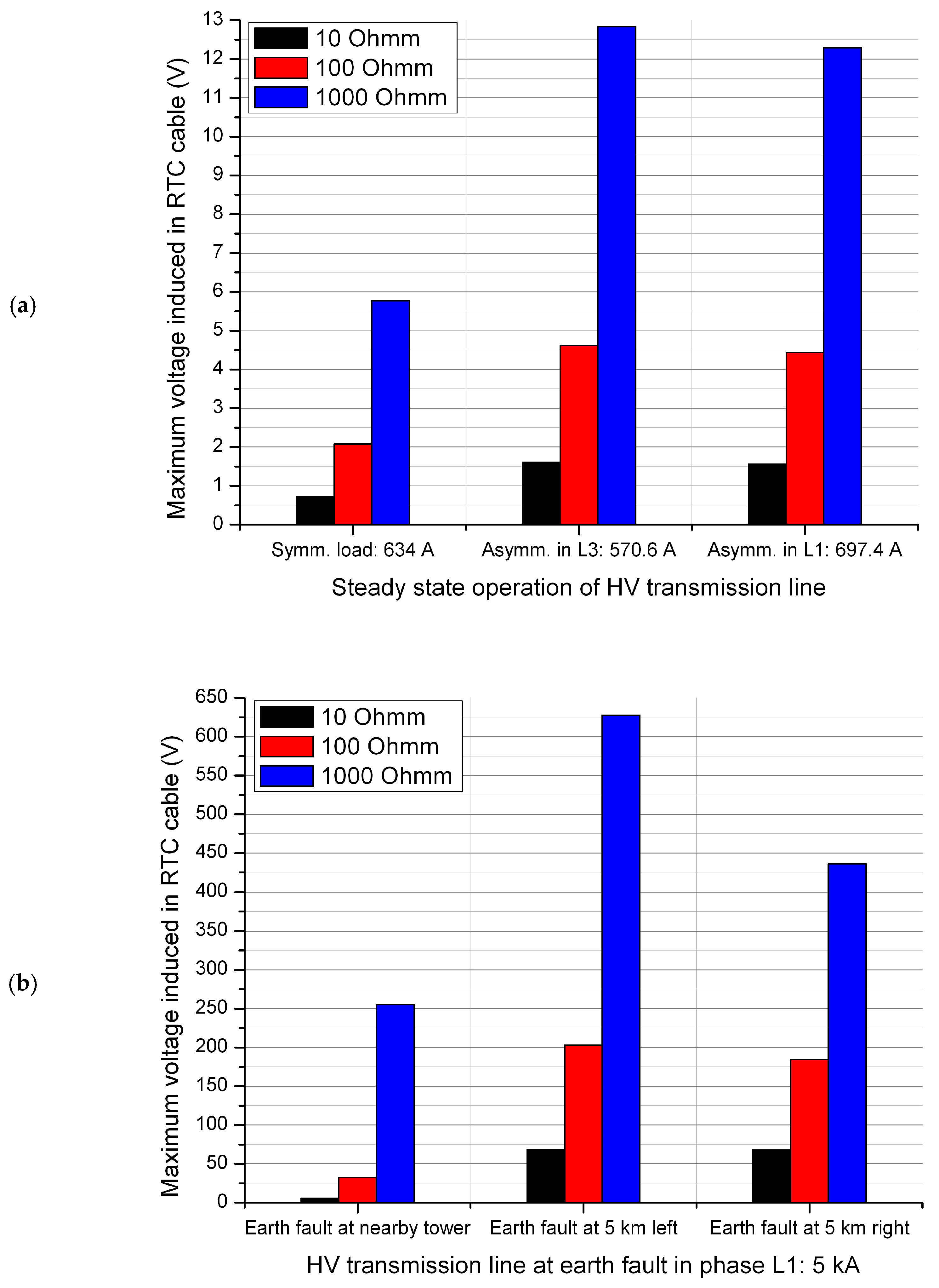
- Normal operation of the HV transmission line under a symmetrical load, with phase currents equal to the nominal current IN = 634 A.
- Normal operation of the HV transmission line under asymmetrical load, with one of the phase currents equal to 0.9 IN = 571 A or 1.1 IN = 697 A.
- Phase-to-ground fault at the tower closest to the place of crossing the signaling cable with the HV line and at the towers located 5 km left and right from that tower, with fault current IF = 5 kA.
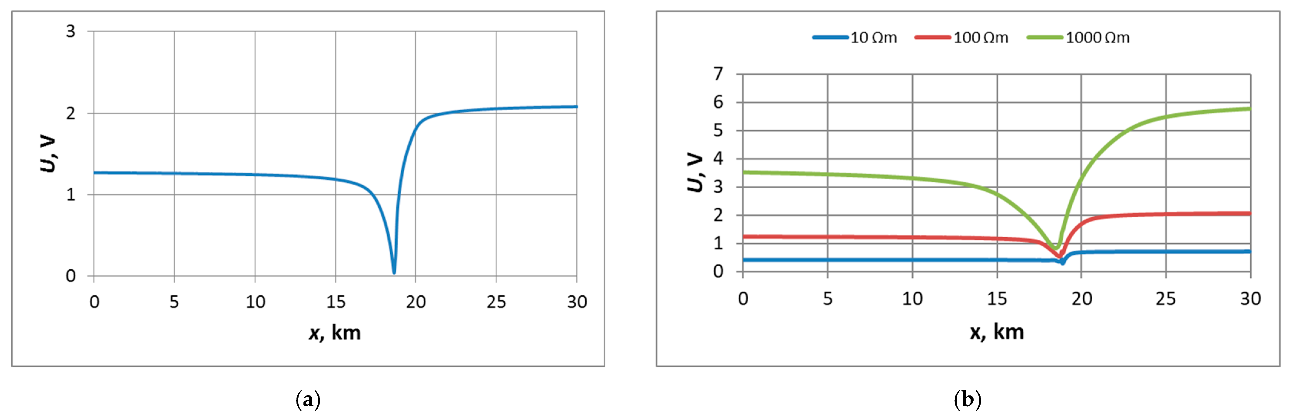
3.1. Normal, Steady-State Operation of the HV Power Line at Nominal Load—Inductive Coupling Effect
3.1.1. Symmetrical Load with Phase Currents Equal to the Nominal Current IN
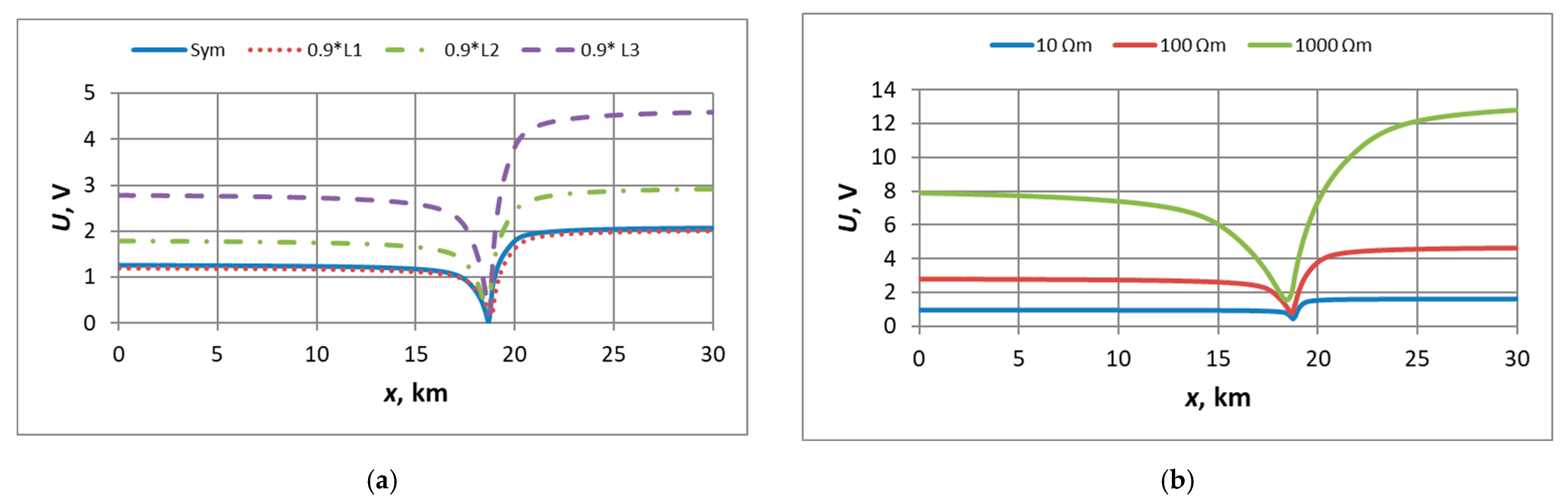
3.1.2. Asymmetrical Load with One of the Phase Currents Equal to 0.9 IN
3.1.3. Asymmetrical Load with One of the Phase Currents Equal to 1.1 IN
3.2. Operation of the HV Transmission Line under the Earth Fault Condition—Inductive Coupling Effect
3.2.1. Earth Fault at the HV Line Tower Nearest to the RTC Signaling Cable
3.2.2. Earth Fault at the HV Line Tower Distant from the Signaling Cable to the Left (Rzesz)
3.2.3. Earth Fault at the HV Line Tower Distant from the Signaling Cable to the Right (Wid)
3.3. Operation of the HV Transmission Line under the Earth Fault Condition—Conductive Coupling Effect
4. Discussion
- A ten-fold higher soil resistivity leads to around 2.7–3 times higher maximum values of the induced voltage;
- A 10% decrease in current in the phase L3 wire located farther from the signaling cable or a 10% increase in the current in the phase L1 wire located closer to the cable causes the increase of the maximum value of the induced voltage around 2.1–2.3 times with respect to the reference case of normal operation with symmetrical load.
- The earth fault at the HV line tower nearest to the signaling cable results in much lower maximum values of the voltages induced in the cable than the distant earth faults. This is due to the fact that the fault current flows to the fault place on the tower nearest to the cable from both directions, which causes the cancellation of voltage components originating from the HV line sections located left and right to that place, whereas in the case of a distant fault, the current flows in one direction over that place;
- In the case of a nearby earth fault, unlike in all the other cases, the maximum value of the induced voltage occurs at end 1 of the signaling cable, which is mainly due to the different directions of the fault currents at both sides of the fault place and the asymmetry of the layout of the HV transmission line with respect to the signaling cable;
- The highest maximum values of the voltages induced in the signaling cable occurred in the case of a distant earth fault located left (direction Rzesz) from the tower nearest to the cable, which again might be explained by the asymmetry of the layout of the HV transmission line with respect to the signaling cable;
- In the case of the distant earth fault located right (direction Wid) from the tower nearest to the signaling cable, the maximum values of the voltages induced in the cable are comparable to those obtained for the case of the distant earth fault located left. However, unlike the other fault places, the increase in voltage with respect to the reference case of the normal operation of the HV line with symmetrical load is getting lower with increasing soil resistivity;
- In the case of the nearby earth fault, 10 times increase in soil resistivity for low-resistivity soils, i.e., from 10 Ωm to 100 Ωm, caused an increase in the maximum voltage induced in the signaling cable of about 5.9 times, whereas a 10 times increase in soil resistivity for high-resistivity soils, i.e., from 100 Ωm to 1000 Ωm, caused an increase in the maximum voltage induced in the cable of 7.8 times;
- In the cases of distant earth faults, the increase in the maximum value of the voltage induced in the signaling cable with increasing soil resistivity is similar to that in normal operation of the HV line, i.e., increasing the soil resistivity 10 times resulted in the increase of the voltage about 2.9 times and 3.1 times for low- and high-resistivity soil, respectively, in the case of a fault located left, and about 2.7 times and 2.4 times for low- and high-resistivity soil, respectively, in the case of a fault located right.
5. Conclusions
- A variety of RTC devices;
- Multi-parameter dependence of the system: traction network, return network, and cable network.
Author Contributions
Funding
Data Availability Statement
Conflicts of Interest
References
- Dąbrowa-Bajon, M. Podstawy Sterowania Ruchem Kolejowym; Oficyna Wydawnicza Politechniki Warszawskiej: Warszawa, Poland, 2002. [Google Scholar]
- Białoń, A.; Zając, W. Badanie zakłóceń lokomotyw tyrystorowych dużych mocy na urządzenia sterowania ruchem. In Proceedings of the Konferencja Naukowo-Techniczna Oddziaływanie Trakcji Elektrycznej na Środowisko i Pierwsza Szkoła Kompatybilności Elektromagnetycznej w Transporcie Szynowym, Zakopane, Poland, 14–16 October 1999. [Google Scholar]
- Laskowski, M.; Malesa, R.; Wróbel, Z. Określenie Istniejących Poziomów Zakłóceń Elektromagnetycznych w Ruchomych i Stacjonarnych Obiektach Kolejowych; Praca CNTK (Zakład Telekomunikacji) nr 1049/24: Warszawa, Poland, 1997. [Google Scholar]
- Laskowski, M.; Wróbel, Z. Poziomy zaburzeń elektromagnetycznych w energetycznej sieci pokładowej niskiego napięcia pojazdów trakcyjnych i wagonów pasażerskich. In ”Problemy Kolejnictwa”, 50 lat Problemów Kolejnictwa; Zeszyt 143; Centrum Naukowo-Techniczne Kolejnictwa: Warszawa, Poland, 2006. [Google Scholar]
- Laskowski, M.; Wróbel, Z. Poziomy zaburzeń radioelektrycznych i impulsowych zaburzeń elektromagnetycznych w energetycznej sieci niskiego napięcia, zasilającej stacjonarne obiekty kolejowe. In Problemy Kolejnictwa; Zeszyt 145; Centrum Naukowo-Techniczne Kolejnictwa: Warszawa, Poland, 2007. [Google Scholar]
- Michna, S. Kłopotliwe zakłócenia obwodów kontroli niezajętości–czyli kompatybilność taboru z urządzeniami przytorowymi. In Infrastruktura Transportu; Elamed MEDIA GROUP: Katowice, Poland, 2011; Volume 5. [Google Scholar]
- Zabłocki, W. Modelowanie stacyjnych systemów sterowania ruchem kolejowym. In Prace Naukowe TRANSPORT; Zeszyt 65; Oficyna Wydawnicza Politechniki Warszawskiej: Warszawa, Poland, 2008. [Google Scholar]
- EN 50129:2003/AC:2010; Zastosowania Kolejowe—Systemy Łączności, Przetwarzania Danych i Sterowania ruchem—Elektroniczne Systemy Sterowania Ruchem Związane z Bezpieczeństwem. Available online: https://www.globalspec.com/ (accessed on 17 May 2024).
- EN 50159:2010; Zastosowania Kolejowe—Systemy Łączności, Sterowania Ruchem i Przetwarzania Danych—Łączność Bezpieczna w Systemach Transmisyjnych. Available online: https://www.globalspec.com/ (accessed on 17 May 2024).
- Pawlik, M. (Ed.) Interoperacyjność Systemu Kolei UE, Infrastruktura, Sterowanie, Energia, Tabor; KOW: Warszawa, Poland, 2015; ISBN 978-83-943085-0-6. [Google Scholar]
- Pawlik, M. Europejski System Zarządzania Ruchem Kolejowym, Przegląd Funkcji i Rozwiązań Technicznych—OD idei do Wdrożeń i Eksploatacji; KOW: Warszawa, Poland, 2015; ISBN 978-83-943085-1-3. [Google Scholar]
- Napolitano, F.; Borghetti, A.; Nucci, C.A.; Rachidi, F.; Paolone, M. Use of the full-wave Finite Element Method for the numerical electromagnetic analysis of LEMP and its coupling to overhead lines. Electr. Power Syst. Res. 2013, 94, 24–29. [Google Scholar] [CrossRef]
- Wróbel, Z. The Horn Gap Arresters Modelling in a Lightning Discharge Analysis. In Proceedings of the 13th Scientific Conference on Selected Issues of Electrical Engineering and Electronics (WZEE), Rzeszow, Poland, 4–8 May 2016; Analysis and Simulation of Electrical and Computer Systems; Lecture Notes in Electrical Engineering. Volume 452, pp. 289–303. [Google Scholar]
- Wróbel, Z. Surge threats appear in railway devices feeding lines. In Proceedings of the 34th International Conference on Lightning Protection, ICLP2018, Rzeszow, Poland, 2–7 September 2018; p. 8503380. [Google Scholar]
- Wróbel, Z. The Group and Individual Connection to the Rail System Modelling in a Lightning Discharge Analysis. In Proceedings of the 11th Scientific Conference on Selected Issues of Electrical Engineering and Electronics (WZEE), Rzeszow, Poland, 27–30 September 2013; Analysis and Simulation of Electrical and Computer System; Book Series: Lecture Notes in Electrical Engineering, 2015. Volume 324, pp. 393–410. [Google Scholar]
- Wróbel, Z. Simulation Possibility of Performance of Avalanche Diode Using a Combination Wave Generator. In Proceedings of the 20th IEEE International Symposium on Industrial Electronics (ISIE), Gdansk, Poland, 27–30 June 2011. [Google Scholar]
- Wróbel, Z. The use of the PN-EN 62305-2 standard to the risk assessment of losses in the equipped object in station-devices of the railway traffic controlling. In Proceedings of the 13th International Conference Modern Electrified Transport (MET), Warsaw, Poland, 5–7 October 2017; Book Series: MATEC Web of Conferences, 2018. Volume 180, p. 05006. [Google Scholar]
- Wróbel, Z.; Jagiełło, A.S. The Risk of Lightning Losses in a Structure Equipped with RTC Devices According to the Standard EN 62305-2.2008.2021. Energies 2021, 14, 1704. [Google Scholar] [CrossRef]
- Markowska, R.; Wróbel, Z. Selected Issues of Safe Operation of the Railway Traffic Control System in the Event of Exposition to Damage Caused by Lightning Discharges. Energies 2021, 14, 5808. [Google Scholar] [CrossRef]
- Mielnik, R.; Wróbel, Z. Integrated power supply system for station equipment of rail traffic control. In Proceedings of the 13th International Conference Modern Electrified Transport (MET), Warsaw, Poland, 5–7 October 2017; Book Series: MATEC Web of Conferences, 2018. Volume 180, p. 05004. [Google Scholar]
- Mielnik, R.; Wróbel, Z. The use of renewable energy sources in the power supply systems of selected level crossings devices. In Proceedings of the 34th International Conference on Lightning Protection, ICLP2018, Rzeszow, Poland, 2–7 September 2018. [Google Scholar] [CrossRef]
- Mickiewicz, T. Oddziaływanie Trakcji Elektrycznej na Urządzenia Zabezpieczenia Ruchu Kolejowego; Wydawnictwa Komunikacji i Łączności: Warszawa, Poland, 1968. [Google Scholar]
- Machczyński, W. Oddziaływania Elektromagnetyczne na Obwody Ziemnopowrotne–Rurociągi Podziemne; Wydawnictwo Politechniki Poznańskiej: Poznań, Poland, 1998. [Google Scholar]
- Machczyński, W.; Sokolski, W. Oddziaływanie Indukcyjne Linii Elektroenergetycznych Wysokiego Napięcia na Gazociągi–Część I. In Ochrona Przed Korozją; SIGMA-NOT: Warsaw, Poland, 2005; Volume 8, pp. 267–271. Available online: https://sigma-not.pl/ (accessed on 17 May 2024).
- Bąchorek, W.; Kot, A.; Nowak, W.; Szpyra, W.; Tarko, R. Problemy projektowania i eksploatacji napowietrznych linii elektroenergetycznych w aspekcie pól elektromagnetycznych. In Proceedings of the V Konferencja Naukowo-Techniczna Elektroenergetyczne Linie Napowietrzne, PTPiREE, Dźwirzyno, Poland, 15 May 2012; pp. 6-1–6-11. [Google Scholar]
- Nowak, W.; Tarko, R.; Jaglarz, A.; Kozioł, J. Analiza warunków eksploatacyjnych linii 110 kV Klikowa–Połaniec i 220 kV Klikowa–Niziny w aspekcie oddziaływania elektromagnetycznego. Energetyka 2006, 2, 118–123. [Google Scholar]
- PSE Operator SA. Linia Napowietrzna 400 kV, Standardowe Specyfikacje Techniczne; Konstancin-Jeziorna, Poland, 2009. Available online: https://www.pse.pl/home (accessed on 17 May 2024).
- Nowak, W.; Tarko, R. Analysis of the feasibility of locating 110 kV line in 400 kV right-of-way in terms of electromagnetic interaction. Acta Energetica 2013, 1, 102–113. [Google Scholar]
- Nowak, W.; Tarko, R. Analiza możliwości lokalizacji linii 110 kV w pasie technologicznym linii 400 kV w aspekcie oddziaływań elektromagnetycznych. Zesz. Nauk. Wydziału Elektrotechniki I Autom. Politech. Gdańskiej 2013, 19–22. [Google Scholar]
- PN-E-05100-1: 1975; Elektroenergetyczne Linie Napowietrzne. Projektowanie i Budowa. Available online: https://sklep.pkn.pl/ (accessed on 17 May 2024).
- PN-EN 50341-1:2013; Elektroenergetyczne Linie Napowietrzne Prądu Przemiennego Powyżej 1 kV. Część 1: Wymagania Ogólne—Specyfikacje Wspólne. Available online: https://sklep.pkn.pl/ (accessed on 17 May 2024).
- PN-EN 50341-2-22:2016; Elektroenergetyczne linie napowietrzne prądu przemiennego powyżej 1 kV. Część 2-22: Krajowe Warunki Normatywne (NNA) dla Polski (oparte na EN 50341-1:2012). Available online: https://sklep.pkn.pl/ (accessed on 17 May 2024).
- PN-EN 50388:2006; Zastosowania Kolejowe: Zasilanie Energią a Tabor. Kryteria Techniczne Dotyczące Koordynacji Zasilania Energią (Podstacja) z Taborem w Celu Uzyskania Interoperacyjności. Available online: https://sklep.pkn.pl/ (accessed on 17 May 2024).
- Rozporządzenie Ministra Środowiska z Dnia 30 Października 2003 r. w Sprawie Dopuszczalnych Poziomów Pól Elektromagnetycznych w Środowisku Oraz Sposobów Sprawdzania Dotrzymania tych Poziomów. Dz.U. nr 192, poz. 1883, Warszawa, Poland, 14 Novermber 2003. Available online: https://isap.sejm.gov.pl/isap.nsf/home.xsp (accessed on 17 May 2024).
- Zeńczak, M. Analiza pola elektrycznego i magnetycznego wokół linii elektroenergetycznych i wybranych urządzeń elektroenergetycznych. Autom. W Energetyce—Napędy I Sterow. 2011, 9, 148–153. Available online: http://beta.nis.com.pl/userfiles/editor/nauka/92011_n/Zeczak_09-2011.pdf (accessed on 17 May 2024).
- Zeńczak, M. Analiza Technicznych Problemów Związanych z Dozymetrią Pól Elektromagnetycznych o Częstotliwości Przemysłowej; Prace Naukowe Politechniki Szczecińskiej: Szczecin, Poland, 1998. [Google Scholar]
- Krakowski, M. Obwody Ziemno Powrotne; Wydawnictwa Naukowo-Techniczne: Warszawa, Poland, 1979. [Google Scholar]
- FFTSES User’s Manual, Fast Fourier Transforms; Safe Engineering Services & Technologies Ltd.: Montreal, Canada, 1997.
- Linie i Stacje Elektroenergetyczne w Środowisku Człowieka (Power Lines and Power Stations in the Human Environment); Informator (Register); PSE–Operator: Warszawa, Poland, 2008; Available online: https://docplayer.pl/7544474-Linie-i-stacje-elektroenergetyczne-w-srodowisku-czlowieka.html (accessed on 17 May 2024).
- Sokólski, W.; Machczyński, W.; Rozwadowski, J. Oddziaływanie indukcyjne linii elektroenergetycznych wysokiego napięcia na gazociągi–Część II. In Ochrona Przed Korozją; SIGMA-NOT: Warsaw, Poland, 2006; Volume 8, pp. 244–248. Available online: https://sigma-not.pl/ (accessed on 17 May 2024).
- Racasan, A.; Munteanu, C.; Topa, V.; Pop, I.T.; Merdan, E. 3D electromagnetic field model for numerical analysis of the electromagnetic interferences between overhead power lines and pipelines. In Proceedings of the 11th International Conference on Electrical Power Quality and Utilisation, Lisbon, Portugal, 17–19 October 2011; pp. 1–6. [Google Scholar] [CrossRef]
- Czumbil, L.; Micu, D.D.; Stet, D.; Ceclan, A. A neural network approach for the inductive coupling between overhead power lines and nearby metallic pipelines. In Proceedings of the 2016 International Symposium on Fundamentals of Electrical Engineering (ISFEE), Bucharest, Romania, 30 June–2 July 2016; pp. 1–6. [Google Scholar] [CrossRef]
- Munteanu, C.; Topa, V.; Mates, G.; Purcar, M.; Racasan, A.; Pop, I.T. Analysis of the electromagnetic interferences between overhead power lines and buried pipelines. In Proceedings of the International Symposium on Electromagnetic Compatibility-EMC EUROPE, Rome, Italy, 17–21 September 2012; pp. 1–6. [Google Scholar] [CrossRef]
- Rabah, D.; Chafik, H.A.; Bessedik, S.A. Electrostatic and electromagnetic effects of HV overhead power line on above metallic pipeline. In Proceedings of the 2017 5th International Conference on Electrical Engineering-Boumerdes (ICEE-B), Boumerdes, Algeria, 29–31 October 2017; pp. 1–6. [Google Scholar] [CrossRef]
- Al Shahri, A.S.; Nair, N.-K.C. Mitigation system for protecting buried pipeline located close to HV OHTL/power cable. In Proceedings of the 2016 IEEE International Conference on Power System Technology (POWERCON), Wollongong, NSW, Australia, 28 September–1 October 2016; pp. 1–6. [Google Scholar] [CrossRef]
- Nourredine, T.; Rabah, D.; Abdechafik, H. Modeling of inductive coupling on aerial metallic Pipeline from HV overhead power line. In Proceedings of the 2022 19th International Multi-Conference on Systems, Signals & Devices (SSD), Sétif, Algeria, 6–10 May 2022; pp. 1813–1819. [Google Scholar] [CrossRef]
- Al Shahri, A.S.; Nair, N.-K.C. Overhead shielding wire and induced potential on pipeline located close to high voltage transmission. In Proceedings of the 2016 Australasian Universities Power Engineering Conference (AUPEC), Brisbane, QLD, Australia, 25–28 September 2016; pp. 1–4. [Google Scholar] [CrossRef]
- Chai, C.S.; Abidin Ab Kadir, M.Z.; Izadi, M.; Jasni, J.; Gomes, C. The effect of electromagnetic fields due to hv line on the parallel pipeline. In Proceedings of the 2014 IEEE International Conference on Power and Energy (PECon), Kuching, Malaysia, 1–3 December 2014; pp. 21–26. [Google Scholar] [CrossRef]
- ANSI/IEEE 80:2013; IEEE Guide for Safety in AC Substation Grounding. IEEE: Piscataway, NJ, USA, 2013. [CrossRef]
- Harun, Z.A.; Osman, M.; Ariffin, A.M.; Zainal Abidin Ab Kadir, M. Effect of AC Interference on HV Underground Cables Buried Within Transmission Lines Right of Way. In Proceedings of the 2021 IEEE International Conference on the Properties and Applications of Dielectric Materials (ICPADM), Johor Bahru, Malaysia, 11–15 July 2021; pp. 73–76. [Google Scholar] [CrossRef]
- Shen, M.; Shah, S.; Eftekhari, R. Study of electromagnetic interference on distribution conductors from parallel transmission line and practical mitigation solutions. In Proceedings of the 2014 IEEE PES T&D Conference and Exposition, Chicago, IL, USA, 14–17 April 2014; pp. 1–9. [Google Scholar] [CrossRef]
- Xing, L.; Wen, Y.; Xiao, J.; Chen, S.; Zhang, D.; Ma, C. Low frequency magnetic protection design of railway signal lines on rail-road bridge. In Proceedings of the 2017 7th IEEE International Symposium on Microwave, Antenna, Propagation, and EMC Technologies (MAPE), Xi’an, China, 24–27 October 2017; pp. 268–272. [Google Scholar] [CrossRef]
- Zhang, L.; Zhu, Y.; Chen, S.; Zhang, D. Research on the Magnetic Effect of Ground-laid Traction Net Protective Wire on the Signal Cable. In Proceedings of the 2020 6th Global Electromagnetic Compatibility Conference (GEMCCON), Xi’an, China, 20–23 October 2020; pp. 1–4. [Google Scholar] [CrossRef]
- How to… Engineering Guide: SESTLC–EM Field and AC Interference Study; Safe Engineering Services & Technologies Ltd.: Laval, QC, Canada, 2017.
- Dawalibi, F.P.; Southey, R.D. Analysis of electrical interference from power lines to gas pipelines, Part I: Computation methods. IEEE Trans. Power Deliv. 1989, 4, 1840–1846. [Google Scholar] [CrossRef]
- Dawalibi, F.P.; Southey, R.D. Analysis of electrical interference from power lines to gas pipelines, Part II: Parametric analysis. IEEE Trans. Power Deliv. 1990, 5, 415–421. [Google Scholar] [CrossRef]
- Łapiński, T.; Perkowski, Z. Przewody Telekomunikacyjne; WKŁ: Warszawa, Poland, 1972. [Google Scholar]
- IEEE Std 1410-2004; IEEE Guide for Improving the Lightning Performance of Electric Power Overhead Distribution Lines. IEEE: Piscataway, NJ, USA, 2004.


| Operation Conditions of the HV Transmission Line | HV Line Current | Soil Resistivity | Maximum Voltage in the Signaling Cable | |||
|---|---|---|---|---|---|---|
| Value (A) | Times Higher Than Reference | (Ωm) | Occurrence at End 1 (V) | Occurrence at End 2 (V) | Times Higher Than Reference | |
| Symmetrical load with nominal current IN * | 634 | 1 | 10 | 0.7 | 1 | |
| 100 | 2.1 | 1 | ||||
| 1000 | 5.8 | 1 | ||||
| Asymmetrical load with current of 0.9 IN in phase L3 | 571 | 0.9 | 10 | 1.6 | 2.3 | |
| 100 | 4.6 | 2.2 | ||||
| 1000 | 12.8 | 2.2 | ||||
| Asymmetrical load with current of 1.1 IN in phase L1 | 697 | 1.1 | 10 | 1.6 | 2.3 | |
| 100 | 4.4 | 2.1 | ||||
| 1000 | 12.3 | 2.1 | ||||
| Earth fault in phase L1 at the HV line tower nearest to the RTC signaling cable | 5000 | 7.9 | 10 | 5.5 | 7.9 | |
| 100 | 32.6 | 15.5 | ||||
| 1000 | 255.2 | 44 | ||||
| Distant earth fault in phase L1 at the HV line tower, left from the tower nearest to the cable | 5000 | 7.9 | 10 | 68.8 | 98.3 | |
| 100 | 203 | 96.7 | ||||
| 1000 | 627.8 | 108.2 | ||||
| Distant earth fault in phase L1 at the HV line tower, right from the tower nearest to the cable | 5000 | 7.9 | 10 | 67.9 | 97 | |
| 100 | 184.6 | 87.9 | ||||
| 1000 | 436.1 | 75.2 | ||||
| Description of the Case | Maximum Voltage Induced (V) | ||||
|---|---|---|---|---|---|
| Ref. | Exposed Line | High-Voltage Line | Mutual Location | Steady-State of HV Line | Earth Fault in HV Line |
| [40] | Buried pipeline; length 37 km; straight route | Double-track HV transmission line; 400 kV/220 kV; irregular route | Parallel route 16 km; distance 50–200 m; crossing with angle 90° | 57–122 | - |
| [41,43] | Buried pipeline; length 1–10 km; straight route | HV transmission line 345 kV; straight route | Parallel route 1–10 km; distance 1–25 m | 4.4 | 4200 |
| [42] | Buried pipeline; length 10 km; straight route | HV transmission line 400 kV; straight route | Parallel route 10 km, distance 30–150 m; 3-layer horizontal soil structure | 40 | 450 |
| [44] | Aboveground pipeline; length 10 km; straight route | HV transmission line 400 kV; straight route | Parallel route 10 km; distance 0–50 m; electrostatic and electromagnetic induction | 3800 | - |
| [45] | Buried pipeline; length 3.5 km; straight route | HV transmission line and underground HV power cable 132 kV; length 5 km; straight route | Parallel route 3.5 km; distance 150 m | 1.6 (HV cable) 9.5 (HV line) | 165 (HV cable) 430 (HV line) |
| [46] | Aboveground pipeline; length 15 km; straight route | HV transmission line 220 kV; straight route | Parallel route 15 km; distance 0–60 m | 340 | |
| [47] | Buried pipeline; length 15 km; straight route | HV transmission line 220 kV; length 15 km, straight route | Parallel route 15 km | 28 | 3348 |
| [50] | Underground HV power cable 275 kV; length 1 km/3 km/5 km; straight route | Double-circuit HV transmission line 275 kV; length 5 km; straight route | Parallel route 1 km/3 km/5 km; distance 19 m | HV cable sheath: 43–182 (both cable and line energized) | - |
| [51] | Distribution line 25 kV; length 5 km; straight route | HV transmission line 110 kV; length 10 km; straight route | Parallel route 5 km; distance 12 m | Neutral (single point grounded): 0.3 (capacitive) 60 (inductive) | - |
| [52] | Railway signal line; straight route | HV transmission line; short circuit 35 kA; straight route | Parallel route 2 m/4 m/6 m; distance 11 m | - | 8.6–26.1 (signal line) 8.5–25.6 (protective tray) |
| [53] | Railway signal cable on the ground; length 30 km | Traction network; length 30 km | Parallel route 30 km; distance to protective wire 0.675 m/7.1 m | Longitudinal electromotive force: 56–89 | - |
| Present | Buried railway signal cable; length 30 km; straight route | HV transmission line 110 kV; length 22 km; straight route | Crossing with an angle of 60° | 2.1–4.6 | 32.6–203 |
Disclaimer/Publisher’s Note: The statements, opinions and data contained in all publications are solely those of the individual author(s) and contributor(s) and not of MDPI and/or the editor(s). MDPI and/or the editor(s) disclaim responsibility for any injury to people or property resulting from any ideas, methods, instructions or products referred to in the content. |
© 2024 by the authors. Licensee MDPI, Basel, Switzerland. This article is an open access article distributed under the terms and conditions of the Creative Commons Attribution (CC BY) license (https://creativecommons.org/licenses/by/4.0/).
Share and Cite
Wróbel, Z.; Ziemba, R.; Markowska, R.; Mielnik, R. Electromagnetic Impact of Overhead High-Voltage Lines during Power Transmission on Buried Signaling Cables of the Traffic Control Systems in Modernized Railway Lines. Energies 2024, 17, 2554. https://doi.org/10.3390/en17112554
Wróbel Z, Ziemba R, Markowska R, Mielnik R. Electromagnetic Impact of Overhead High-Voltage Lines during Power Transmission on Buried Signaling Cables of the Traffic Control Systems in Modernized Railway Lines. Energies. 2024; 17(11):2554. https://doi.org/10.3390/en17112554
Chicago/Turabian StyleWróbel, Zofia, Robert Ziemba, Renata Markowska, and Ryszard Mielnik. 2024. "Electromagnetic Impact of Overhead High-Voltage Lines during Power Transmission on Buried Signaling Cables of the Traffic Control Systems in Modernized Railway Lines" Energies 17, no. 11: 2554. https://doi.org/10.3390/en17112554