Article

First Successful Wireline Stress Testing in a Gas Hydrate Reservoir in the Hyuganada Sea, Japan

1
Japan Organization for Metals and Energy Security (JOGMEC), 1-2-2 Hamada Mihama-ku, Chiba-shi, Chiba 261-0025, Japan
2
Schlumberger K.K., 2-14-30 Hokuyo, Nagaoka-shi, Niigata 940-0871, Japan
3
Japan Methane Hydrate Operating Co., Ltd. (JMH), 1-7-12 Marunouchi, Chiyoda-ku, Tokyo 100-0005, Japan
*
Authors to whom correspondence should be addressed.
Current address: Japan Petroleum Exploration Co., Ltd. (JAPEX), 1-7-12, Marunouchi, Chiyoda-ku, Tokyo 100-0005, Japan.
Energies 2024, 17(11), 2610; https://doi.org/10.3390/en17112610
Submission received: 30 January 2024 / Revised: 16 May 2024 / Accepted: 21 May 2024 / Published: 28 May 2024

Abstract

:
This study presents a stress testing operation conducted using a wireline formation tester in a newly discovered gas hydrate prospect located offshore in Japan. The campaign, which spanned from December 2021 to January 2022, involved drilling a well using logging-while-drilling technology. Subsequently, wireline formation testing and stress testing were successfully conducted at three different depths within a gas hydrate-concentrated zone. The testing was accomplished in a single riserless descent, with the primary goal of obtaining crucial data such as mobility, formation pressure, and fracture gradient for one of the prospects. This operation marked the first stress testing job performed with dual packers in an open water and deepwater environment specifically for gas hydrate reservoirs. The study also provides a comprehensive interpretation of the data gathered during the operation. Moreover, it evaluates various properties such as formation mobility, formation pressure, initial breakdown pressure, closure pressure, fracture propagation pressure, and instantaneous shut-in pressure.

1. Introduction

Natural gas hydrates are expected to become an alternative hydrocarbon resource with the capacity to support replenishing the conventional natural gas supply. Laboratory studies, modeling, simulations, and short-term field gas production tests have demonstrated that extracting gas from gas hydrate-bearing reservoirs via depressurization is technically feasible. However, there has not been a long-term demonstration of gas production from such reservoirs. The MH21-S R&D consortium (MH21-S), consisting of the Japan Organization for Metals and Energy Security (JOGMEC), the National Institute of Advanced Industrial Science and Technology (AIST), and the Japan Methane Hydrate Operating Co., Ltd. (JMH), has been continuously working to develop technologies for extracting natural gas from gas hydrate-bearing reservoirs. MH21-S initiated a pre-exploration drilling campaign targeting new gas hydrate prospects located offshore in Japan. As a key part of this campaign, which ran from December 2021 to January 2022, a well was drilled using logging-while-drilling (LWD) technology in the Hyuganada Sea. Following this, wireline formation testing and stress testing were successfully conducted at three different depths within a gas hydrate-concentrated zone. The testing was accomplished in a single riserless descent with the objective of obtaining crucial data on mobility, formation pressure, and fracture gradient in a prospect situated in the Hyuganada Sea (Figure 1).
This study focuses on a stress testing operation conducted using a wireline formation tester (WFT) and acquires data specifically for gas hydrate reservoirs. Furthermore, it evaluates various hydraulic and mechanical properties such as formation mobility, formation pressure, initial breakdown pressure, closure pressure, fracture propagation pressure, and instantaneous shut-in pressure (ISIP).

2. Challenges and Objectives of WFT and Stress Testing

Historical gas hydrate production tests have shown that geomechanical instability represents a major challenge to the exploitation of gas hydrate reservoirs. Found in considerably shallow and unconsolidated formations, gas hydrates undergo physical changes owing to the applied production techniques and dissociation during production. These changes can cause mechanical effects such as deformation and formation failure (e.g., formation collapse after hydrate dissociation), potentially leading to issues in gas production operations [1]. Stress is a vital parameter when characterizing the mechanical properties of formations.
In the past, anelastic strain recovery (ASR) [2] measurements and numerical modeling based on a multiphase simulator [3,4,5,6] have been conducted in locations such as the Nankai Trough. However, these methods do not provide direct measurements under real downhole pressure and temperature conditions. Stress testing using a WFT is a technology suited for obtaining the representative mechanical properties of formations. Although it was used in the Mallik, Daini-Atsumi, and Iġnik Sikumi wells in cased-hole and drill pipe conveyance environments, the associated operation costs were extremely high. A wireline riserless open-hole operation is a considerably more cost-effective alternative for acquiring critical data, such as the fracture gradient essential for wellbore stability studies. However, there is no precedent for this operation with respect to stress testing in gas hydrate applications owing to several concerns. First, stress testing intentionally breaks a formation and creates fractures, causing a risk to well control in a riserless operation. Moreover, the cycle of a proper stress testing operation at a single depth station, encompassing injection, fracturing, and repeated observation of the falloff, can extend over several hours. This duration increases the risk of a tool getting stuck in an unconsolidated formation environment, particularly when combined with potential differential pressure. A tool recovery operation in deepwater environments, devoid of risers or guide pipes, poses even greater risks. Therefore, addressing the two major concerns, namely well control and tool recovery, is paramount, requiring careful evaluation of geological conditions and operational procedures, beyond ensuring measurement integrity.
In addition to determining the fracture gradient, the second objective is to evaluate formation properties such as formation mobility to understand the permeability profile in gas hydrate zones. The operational procedure described in this paper was designed to meet both objectives.

3. Review of Past WFT Cases in Gas Hydrate Operations

3.1. Overview of Past WFT Cases in Gas Hydrate Operations

Before embarking on offshore field operations, it is imperative to conduct a thorough examination and address numerous considerations. This is particularly crucial for the first exploratory drilling in a new prospect, where the deployment strategy plays a pivotal role in ensuring the success of an operation. The ongoing challenge posed by unconsolidated formations in offshore fields, which can affect measurement quality, necessitates thorough planning. Therefore, extensive reviews of past WFT formation testing programs and other formation testers used in gas hydrate applications have been conducted. The objective of this review is to draw lessons from these experiences and create an optimal logging program that effectively captures data on mobility, formation pressure, and fracture gradient data in the Hyuganada Sea.
Between 2002 and 2015, at least six notable instances of formation testing field operations using a WFT and other formation testers were reported in gas hydrate applications, both onshore and offshore (Table 1) [7,8,9,10,11,12,13]. These tests aimed to measure various parameters, including formation pressure, mobility, or fracture gradient via injection as well as to collect gas or water samples. Although there was an additional instance of WFT usage in the Nankai Trough in 1999, it has been excluded from this discussion owing to its objectives not being solely focused on gas hydrate exploration.
As indicated in Table 1, acquiring fracture gradient data in an open-hole, offshore environment within a gas hydrate reservoir, similar to the conditions encountered in this campaign in the Hyuganada Sea, lacks precedent. However, dual-packer modules paired with a WFT have been deployed in a few instances.

3.2. Review of Fracture Gradient Measurement by WFT in Gas Hydrate Operations

Three cases of fracture gradient measurements in gas hydrate operations, which utilized WFTs and other formation testers, have been documented. Among these, two employed a WFT, while the third used a cased-hole dynamic tester (CHDT). The operational conditions varied: one was conducted in a cased hole on land, another in an offshore cased hole, and the last in an open hole on land.
Mallik 5L-38 cased-hole WFT
In this operation, a WFT was deployed in a cased hole, positioning the dual-packer module across a perforated interval of 0.5 m in 9–5/8-inch casing [7]. However, accurately determining the fracture closure pressure proved challenging owing to the absence of typical fracture breakdown pressure behavior, likely caused by cross-flow from the cementing path.
Conducted on land within a cased hole, this operation presented the least deployment challenge and safety risk among the cases reviewed. The operational conditions and mitigation strategies employed here suggest that the risks identified in the Hyuganada operation could be effectively managed under similar conditions.
Daini-Atsumi No. 31 cased-hole WFT
The extremely unconsolidated nature of the formation in this field necessitated the use of a CHDT. The tool drilled through the 9–5/8-inch casing and injected wellbore fluid to conduct a mini-frac test [8]. The fracture closure pressure was obtained at three depths.
Being an offshore operation with a riser, it utilized a single-packer formation tester operated directly by a hydraulic system, facilitating a much quicker operation than the dual-packer systems that require inflation and deflation using wellbore fluid.
Iġnik Sikumi #1 open-hole WFT
For this operation, a WFT equipped with a dual packer and a full sampling suite was run via a drill pipe. This approach sought to minimize the risk of a stuck tool in the 9–7/8-inch open hole filled with oil-based drilling mud (OBM). The fracture closure pressure was determined at two depths [10].
Although this was an open-hole land operation, utilizing drill pipe conveyance as a mitigation strategy for tool recovery limits its applicability as a direct reference for the Hyuganada campaign. Nevertheless, using OBM to mitigate the risk of a stuck tool offers valuable insights into drilling fluid selection, crucial for maintaining optimal borehole conditions for packer seals, although environmental considerations preclude OBM’s use in riserless operations.
The Hyuganada campaign is unique as it involves open-hole offshore conditions. Therefore, a well-prepared risk mitigation plan was required to increase the likelihood of successful tool deployment and measurement.

4. Geologic Conditions

4.1. Regional Geology

The Hyuganada Sea, located off the eastern coast of the Kyusyu Island in southwest Japan, is characterized by a low-gravity anomaly known as the Miyazaki-oki forearc basin. This basin comprises the Early Miocene to Early Pleistocene Miyazaki Group and the Hyuganada Group. Through the interpretation of 3D seismic volume data, it has been revealed that these groups can reach thicknesses of up to 5000 m in environments ranging from deep to shallow marine settings [14]. Such substantial accumulations of young sediments are believed to contribute significantly to methane generation, which in turn feeds into the gas hydrate reservoirs in the region.

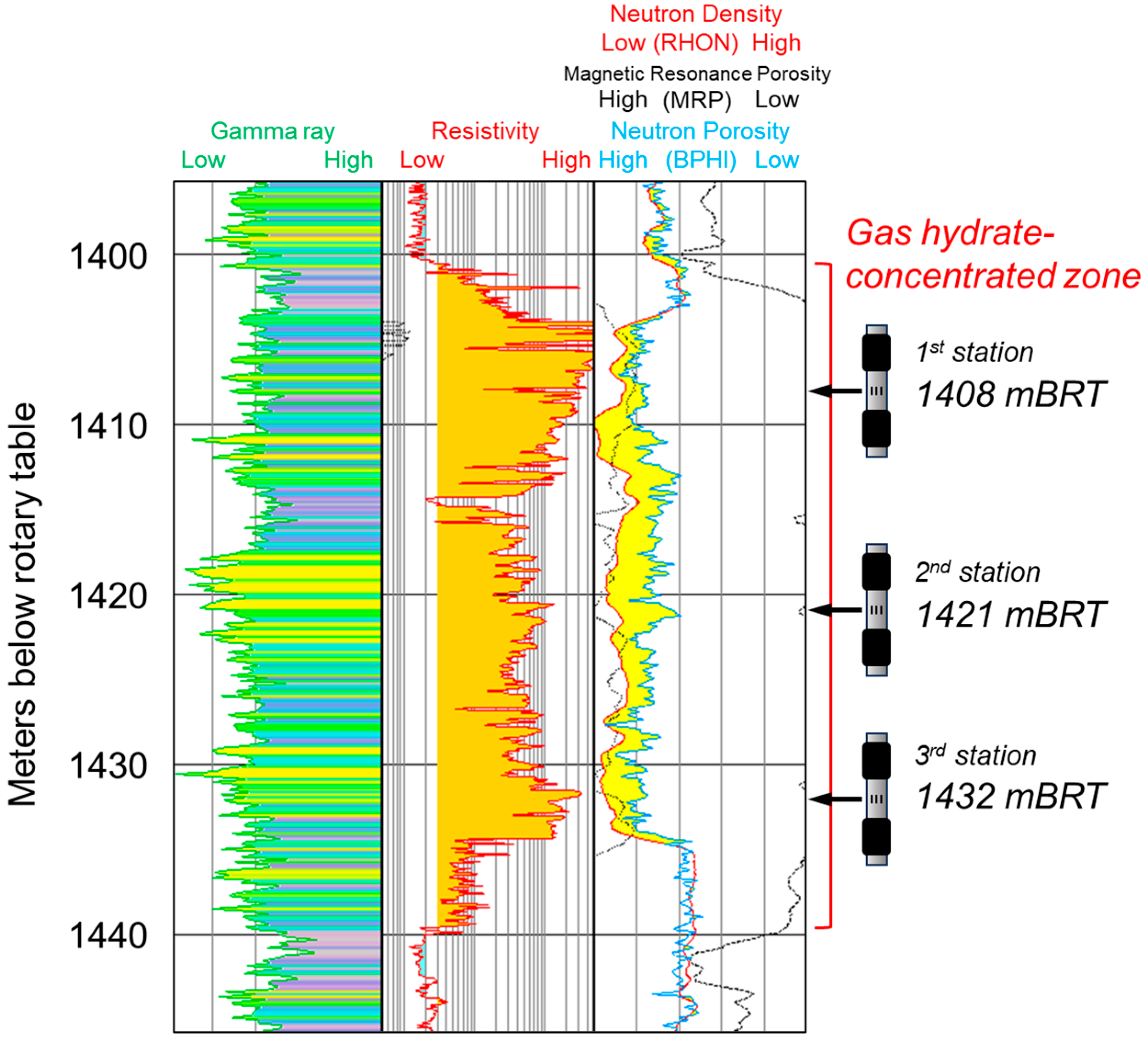
4.2. Reservoir Conditions

The gas hydrate reservoir under study is located within the upper part of the Pliocene Miyazaki Group. The water depth at this site exceeds 1000 m relative to the mean sea level. The top of the reservoir is situated up to 250 m below the sea floor, and the gross vertical thickness of the reservoir can extend up to 35 m. The reservoir is composed of sand-dominant alternating layers of sand and mud. The depositional environment of the reservoir is interpreted as deep marine turbidite lobes based on the formation evaluations conducted using LWD data and microfossil analysis [15]. To ensure borehole stability, the reservoir section was drilled at a slow rate of penetration. Subsequent caliper log confirmed the gaged hole (bit size: 8.5 inch), indicating it is well-suited for effective sealing by the packer module of a WFT.

5. WFT Operation and Data Acquisition

Stress magnitude can be inferred using continuous sonic-based measurements; however, such estimates need to be calibrated using direct stress measurements, such as core experiments or in situ stress measurements conducted through downhole techniques. The unique characteristics of gas hydrates, including phase changes and variations in mechanical properties in response to pressure, temperature, and time, make it challenging to perform stress tests in a core lab setting. Instead, the WFT, a downhole technique, can be adapted as a wireline micro-fracturing tool. This tool is equipped with a high-performance gauge designed to measure injection pressure and falloff across an interval packer [16]. Additionally, this tool string can perform single-run descent pressure measurements. To achieve the testing objective, a packer was selected that satisfies both injection and drawdown requirements with a high degree of pressure gauge accuracy. Table 2 presents the specifications for the key module dual packer and pressure gauge.

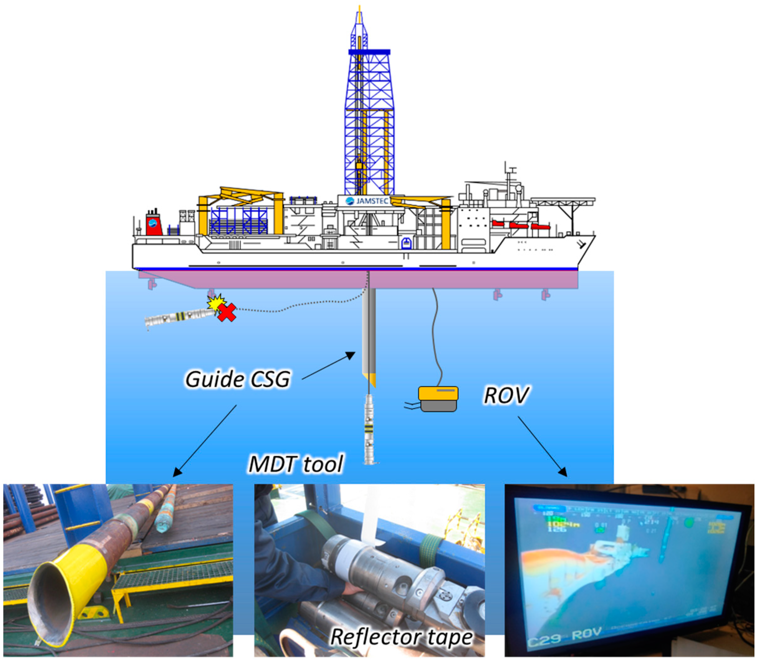
5.1. Operation Preparation

Preparing for a WFT operation in this gas hydrate well necessitated addressing two operational issues: conducting operations in the open water (riserless) environment and drilling with seawater, which might result in the absence of mudcake on the wellbore and potential leaks at the flow inlet (dual packer).
The main challenges associated with open water operations are the following:
  • The potential drift of the wireline cable and tool string owing to ocean currents.
  • Compensating for heave without a fixed reference point.
  • Successfully driving the tool string into the well.
To overcome these challenges, a remotely operated vehicle (ROV) was employed. By painting the tool string fluorescent yellow and applying a reflector tape, visibility was enhanced, allowing the ROV to effectively guide the tool string through the dark sea into the well for the WFT operation (Figure 2). Furthermore, a 9–5/8-inch casing × 56 m guide casing was used to protect the cable from damage caused by the thrusters of the drilling vessel.
To form mudcake on the borehole wall after drilling with seawater, the mud engineer on the rig prepared a special mud system for the wiper trip. This was done to ensure the proper formation of mudcake for the WFT operation. Figure 3 shows the mud sample and mudcake test conducted before the wiper trip to verify the effectiveness of the mud system. The mud consisted of a seawater-based bentonite gel mud with a specific gravity of 1.03, and a funnel viscosity of 151 s/qt.

5.2. Operation Execution

The WFT objectives were achieved through a series of meticulously designed pressure pretests and stress testing, utilizing a dual-packer module. This module functioned as the main inlet of the WFT string. As shown in Figure 4, the gas hydrate zones targeted for testing were isolated at 1 m intervals using both elements of the packer. These packers were inflated with wellbore fluid, effectively isolating the selected sections from the rest of the borehole while sealing against the borehole wall. Following packer inflation, pressure pretests were conducted to determine the formation pressure and mobility. The subsequent phase involved stress testing, where wellbore fluid was injected into a 1 m interval of the formation through a downhole pump module and wireline cable conveyance. After injection, the pressure dissipation was monitored along the pressure and pressure derivative profiles.
Before initiating WFT operations, the interpretation of LWD logs, including nuclear magnetic resonance (NMR), resistivity, neutron density, porosity, sonic velocity, and gamma rays, was carefully processed and finalized to identify the most suitable depths for WFT applications. As shown in Figure 5, three depth stations were selected as test intervals based on their relatively high resistivity (indicative of estimated gas hydrate saturation), located at various segments within the gas hydrate-bearing reservoir, specifically in the top, middle, and bottom sections. Additionally, caliper data for not only the test interval but also for the surrounding formation both below and above the test interval were scrutinized to confirm the absence of hole enlargement, thereby ensuring the effective functioning of the packer.
Given the shallow and unconsolidated nature of gas hydrate formation, it was crucial to carefully manage the pretest drawdown and injection pressure to prevent sand issues, a complication that could severely disrupt the stress testing process. Figure 6a shows a comprehensive test from a stress testing station in the Hyuganada Sea, which included a filtrate test and three injections and falloff cycles. During these operations, two to three cycles were determined in real-time, each consisting of an injection phase followed by a falloff phase. This approach was adopted because increasing the number of cycles might heighten the risk of the tool becoming lodged within the highly unconsolidated formation.
The detailed stress testing illustrated in Figure 6a encompasses five phases. The process begins with an initial filtrate test (cycle 1) aimed at confirming the seal integrity of the dual packer’s seal by injecting mud into the formation at a low flow rate. Following this, the procedure transitions into several hydraulic fracturing cycles (cycles 2−5).

6. Results and Discussion

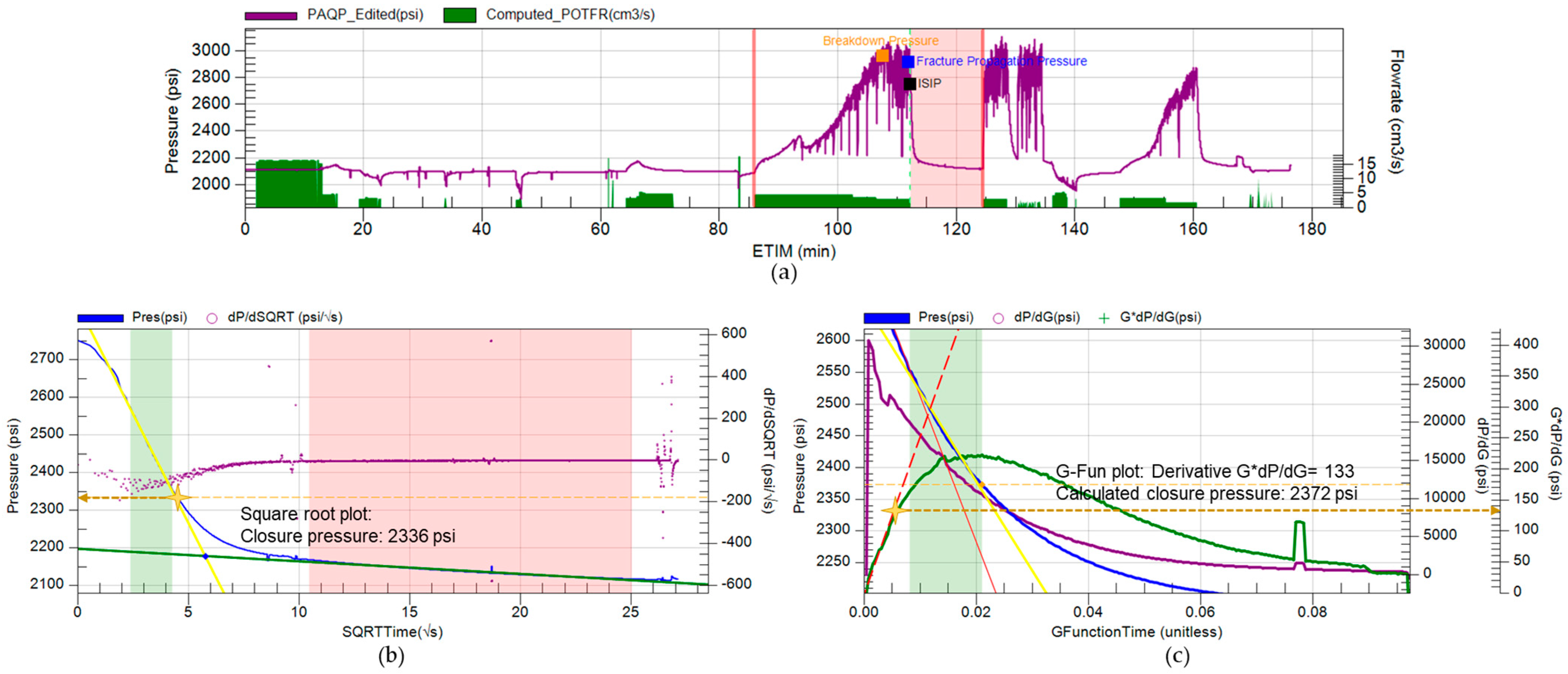
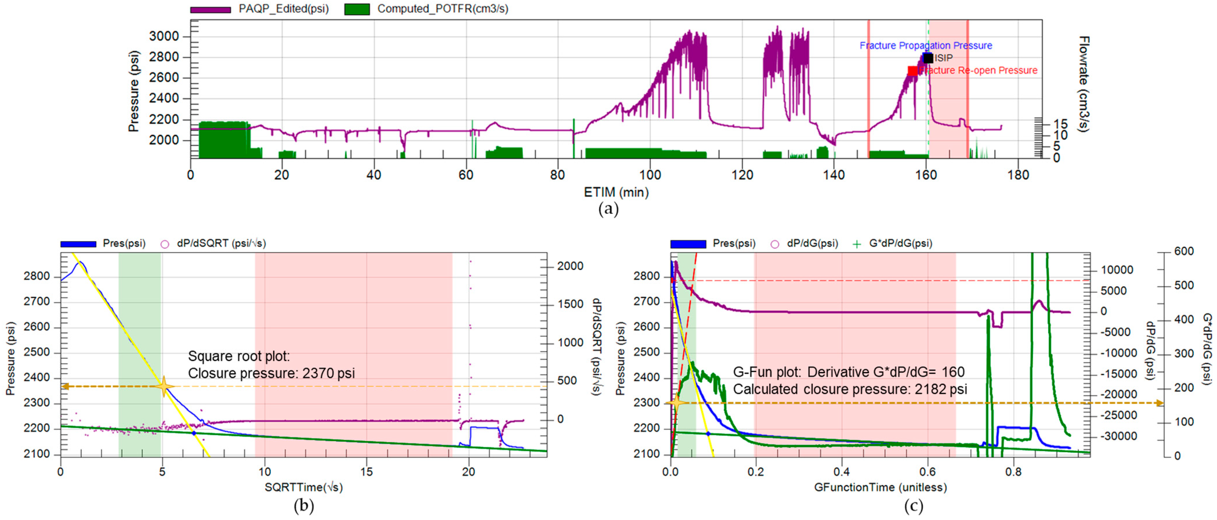
6.1. Stress Testing by WFT

During cycles 2–5, the fluid was continuously injected into the targeted interval at a constant pump speed until the onset of initial tensile failure, also known as fracture breakdown, was observed. Formation breakdown was achieved during the injection of cycle 2. The fracture was then extended for 5 min before the pump was shut off. After that, the pressure declined toward the hydrostatic pressure level, followed by another two cycles of injections/falloff to reopen, propagate, and close the fracture. The data from falloff in cycles 2 and 5 indicate fracture alignment with the wellbore axis and repeatability across tests, indicating that the far-field stress is measured. The absence of falloff in cycles 3 and 4 suggests that falloff time was insufficient for such observations, despite the alignment and repeatable propagation pressure signature noted in cycle 2. This iterative process not only confirmed the repeatability of the test but also allowed for potential adjustments in injection parameters, such as volume and flow rate. Following cycles 3 and 4, an immediate drawdown test was conducted during the falloff phase (elapsed time: 136.2–146.2 min) to confirm any fracture signature from pressure analysis. Figure 6b shows the pressure transient flow regime transitioning from radial flow to bilinear flow, and then back to radial flow further away from the wellbore. This bilinear flow regime confirmed the fracture induced by stress testing. The cycle 2 data have a very good quality of closure pressure indication, and the plan was to perform one more falloff in cycle 5 to repeat the falloff result, which was conducted nicely and repeated the closure pressure measurement. To reduce the operation time and confirm whether the hydraulic fracture was formed, during real-time we decided to perform drawdown and buildup to validate the hydraulic fracture. Even when we performed falloff in cycle 3, we expected the same result to cycles 2 and 5. From the stress testing operation, fracture breakdown, reopening, and closure pressures were all successfully acquired at three depth stations. As shown in Figure 7 and Figure 8 and Table 3, both G-function and square root (SQRT) plot techniques were used to fracture closure pressure estimation, with both techniques providing consistent results.
Square root plot analysis: The SQRT plot contains pressure and pressure derivative curves (with respect to square root of time since shut-in) plotted against the square root (Δt). This analysis offers a straight line fit for periods before and after closure, allowing for manual picking of the closure point on the pressure curve. In Figure 7 and Figure 8, the intersection of the two straight line slopes from cycles 2 and 5 of falloff was identified as the best representation of closure pressure from the square root time plot. The exact value of closure pressure, as determined by the interpreter, was marked at the upper bound of closure, signifying the departure of the pressure data from the initial straight line and thus representing the best estimate of the max closure.
G-Function plot analysis: The G-function analysis utilizes the G-function concept to compute closure pressure and fracture properties. The G-function represents the elapsed time after shut-in, normalized to the duration of fracture extension [17]. This analysis includes three curves: pressure, its derivative dp/dG, and the G-function semilog derivative G dp/dG, as shown in Figure 7 and Figure 8. By drawing linear flow from the semilog derivative G dp/dG (red dash line in G-function plot), the closure pressure is calculated from the point that departs from the linear flow line; the value of closure pressure is quite aligned with the square root analysis, which confirmed the closure value.
The geomechanical properties of the gas hydrate zone indicated that the formation was relatively homogenous rather than showing strong heterogeneity.

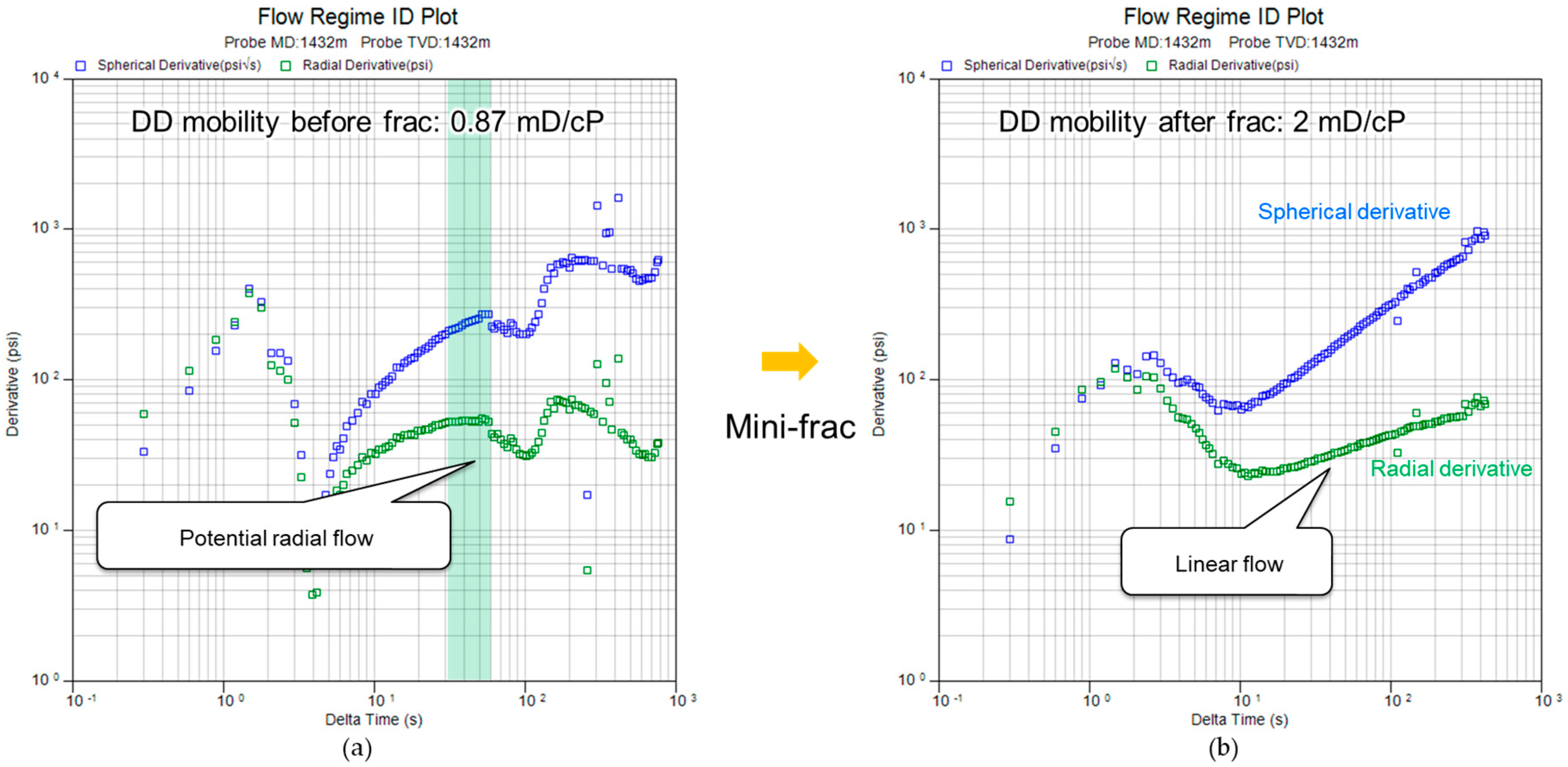
6.2. Pressure Measurement by a Dual Packer

Before conducting stress testing at each depth station, pressure measurements, known as pretests, were performed using a dual-packer module. Each measurement session included one to two repeated tests, with the fluid volume drawn from the formation ranging from hundreds to thousands of milliliters. Unlike single-probe measurements used in other gas hydrate explorations, which only penetrate a maximum of 20 cm owing to the limited pretest volume of 5 to 10 mL, these pretests allowed for a more substantial investigation of the wellbore.
Table 4 presents the formation mobility and buildup pressure observed in each pretest per depth station. A consistent pattern emerged from these measurements: the final buildup pressure recorded in the first pretest at each station was slightly higher than that of the subsequent pretest, indicating a minor degree of supercharging. Similarly, the formation mobility derived from the initial pretest consistently exceeded that measured in the second. Even at the third depth station, where three pretests were conducted, the mobilities recorded in the second and third tests closely matched. This discrepancy can be attributed to the tool storage volume expansion impacting the first pretest. Given the considerable flowline volume of the dual packer, the drawdown pressure observed during the first pretest was not solely from the formation. This explains why the formation mobility from the first pretest was higher compared to subsequent tests.
Figure 9 shows a comparison of the pressure derivatives before and after a mini-frac test. The pressure derivatives illustrate a shift in the flow pattern from a potential radial flow to a fracture linear flow. In addition, following the mini-frac test, the drawdown mobility nearly doubled. These results suggest that stress testing successfully induced fractures within the formation.

7. Recommendations

To improve the data quality in future operations, it is recommended to consider the following strategies:
  • Implementing a rebound test by adding a sample chamber close to the dual packer to the procedure could help confirm the fracture and fine-tune the closure pressure.
  • Conducting additional injection cycles could facilitate the observation of repeated pressure response behaviors, and potentially reduce pressure noise compared with that observed in the initial cycles.

8. Conclusions

The first worldwide WFT stress test was successfully conducted in a deepwater riserless open-hole environment, specifically for gas hydrate reservoirs. This operation was carried out safely and smoothly through the collaborative effort between the operators and the service company. This test was conducted as a part of a pre-exploration drilling activity aimed at identifying a promising candidate site among several gas hydrate prospects, considering the volume of gas hydrate resources in place and their productivity. The primary objectives of the test were achieved, including the acquisition of hydraulic fracture-related properties and determining formation pressure and mobility. The success of this downhole acquisition marks an important milestone in understanding rock mechanical behavior under in situ conditions in gas hydrate reservoirs, providing essential data to complement core tests. This information on gas hydrate-bearing sediments lays a foundational basis for future studies on the hydraulic and mechanical responses of gas hydrate-bearing reservoirs. Such studies are crucial as they inform the planning and execution of drilling, completion, gas production testing, and potential enhanced recovery techniques, such as hydraulic fracturing.

Author Contributions

All authors contributed to the planning, field operation, data analysis, and interpretation work of the WFT stress testing and the publication of this paper. T.Y. (wellsite geologist) led the planning and operation on board; D.W. (wireline tool engineer) operated the WFT on board; S.O. (reservoir engineer) performed technical support on board; B.G. and Z.F. performed remote technical supports during operation; T.K. reviewed past WFT operations in gas hydrate reservoirs and supported the planning of the operation; B.G. and S.O. performed data analysis and interpretation; Y.M. supported the data interpretation and made a presentation at ICGH10; S.O., B.G., T.Y. and T.K. wrote the paper. All authors have read and agreed to the published version of the manuscript.

Funding

This research received no external funding.

Data Availability Statement

No new data were created or analyzed in this study. Data sharing is not applicable to this article.

Acknowledgments

This study was conducted as part of activities that the Ministry of Economy, Trade and Industry (METI), Japan entrusted to the MH21-S R&D consortium (MH21-S). We would like to express our sincere appreciation to METI for providing permission to disclose this research and to SLB for its technical support and cooperation with the operator.

Conflicts of Interest

Author Takanao Yoshii was employed by the company Japan Methane Hydrate Operating Co., Ltd. (JMH). The remaining authors declare that the research was conducted in the absence of any commercial or financial relationships that could be construed as a potential conflict of interest.

Nomenclature

ASRAnelastic strain recovery
BHDBorehole diameter
BPHINeutron porosity
BRTbelow rotary table
BUBuildup
CHCased hole
CHDTCased-hole dynamic tester
CSGCasing
DDDrawdown
ETIMElapsed time
ISIPInstantaneous shut-in pressure
LWDLogging while drilling
MDTModular formation dynamics tester
MRPMagnetic resonance porosity
NMRNuclear magnetic resonance
OBMOil-based drilling mud
OHOpen hole
PAQPQuartz gauge pressure
POTFRTotal pumpout flow rate
RHONNeutron density
ROVRemotely operated vehicle
SQRTSquare root
TVDTrue vertical depth
WFTWireline formation tester

References

  1. Yamamoto, K.; Terao, Y.; Fujii, T.; Ikawa, T.; Seki, M.; Matsuzawa, M.; Kanno, T. Operational overview of the first offshore production test of methane hydrates in the Eastern Nankai Trough. In Proceedings of the Offshore Technology Conference, Houston, TX, USA, 5–8 May 2014. [Google Scholar]
  2. Nagano, Y.; Lin, W.; Yamamoto, K. In-situ stress analysis using the anelastic strain recovery (ASR) method at the first offshore gas production test site in the eastern Nankai Trough, Japan. Mar. Pet. Geol. 2015, 66, 418–424. [Google Scholar] [CrossRef]
  3. Ghezzehei, T.A.; Kneafsey, T.J. Measurements of the Capillary Pressure-Saturation Relationship of Methane Hydrate Bearing Sediments. In Proceedings of the 2010 Offshore Technology Conference, Houston, TX, USA, 3–6 May 2010. [Google Scholar]
  4. Sakamoto, Y.; Komai, T.; Kawamura, T.; Tenma, N.; Yamaguchi, T. Field Scale Simulation for the Effect of Relative Permeability on Dissociation and Gas Production Behavior during Depressurization Process of Methane Hydrate in Marine Sediments. In Proceedings of the 7th ISOPE Ocean Mining Symposium, Lisbon, Portugal, 1–6 July 2007. [Google Scholar]
  5. Mohana, L.; Grozic, J.L.H. Prediction Performance of Permeability Models in Gas-Hydrate-Bearing Sands. SPE J. 2013, 18, 274–284. [Google Scholar]
  6. Yoneda, J.; Takiguchi, A.; Ishibashi, T.; Yasui, A.; Mori, J.; Kakumoto, M.; Aoki, K.; Tenma, N. Mechanical Response of Reservoir and Well Completion of the First Offshore Methane-Hydrate Production Test at the Eastern Nankai Trough: A Coupled Thermo-Hydromechanical Analysis. SPE J. 2019, 24, 531–546. [Google Scholar] [CrossRef]
  7. McLellan, P.; Gillen, K.; Podetz, C.; Dallimore, S.; Inoue, T.; Hancock, S. In situ stresses in the Mallik area. In Scientific Results from the Mallik 2002 Gas Hydrate Production Research Well Program, Mackenzie Delta, Northwest Territories, Canada, Geological Survey of Canada, Bulletin 585; Geological Survey of Canada: Ottawa, ON, Canada, 2005. [Google Scholar]
  8. Yamamoto, K.; Yasuda, M.; Kin, C.; Kusaka, K. Application of Wireline Conveyed Through Casing Formation Tester to Methane Hydrate Research in Japan. In Proceedings of the 11th Formation Evaluation Symposium of Japan, Chiba, Japan, 5–6 October 2005. [Google Scholar]
  9. Boswell, R.; Hunter, R.; Collett, T.; Digert, S.; Hancock, S.; Weeks, M.; Mount Ebert Science Team. Investigation of gas hydrate bearing sandstone reservoirs at the “Mount Elbert” stratigraphic test well, Milne Point, Alaska. In Proceedings of the 6th International Conference on Gas Hydrates (ICGH 2008), Vancouver, BC, Canada, 6–10 July 2008. [Google Scholar]
  10. Schoderbek, D.; Farrel, H.; Hester, K.; Howard, J.; Raterman, K.; Silpngarmlert, S.; Martin, K.L.; Smith, B.; Klein, P. ConocoPhillips Gas Hydrate Production Test Final Technical Report; Prepared by ConocoPhillips Company for the United States Department of Energy, National Energy Technology Laboratory; ConocoPhillips Company: Houston, TX, USA, 2013. [Google Scholar]
  11. Fujii, T.; Suzuki, K.; Takayama, T.; Tamaki, M.; Komatsu, Y.; Konno, T.; Yoneda, J.; Yamamoto, K.; Nagao, J. Geological setting and characterization of methane hydrate reservoir distributed at the first offshore production test site on the Daini-Atsumi Knoll in the eastern Nankai Trough, Japan. Mar. Pet. Geol. 2015, 66 Pt 2, 310–322. [Google Scholar] [CrossRef]
  12. Kumar, P.; Collett, T.; Yadav, U.; Singh, J. Formation pressure and fluid flow measurements in marine gas hydrate reservoirs, NGHP-02 expedition, offshore India. Mar. Pet. Geol. 2019, 108, 609–618. [Google Scholar] [CrossRef]
  13. Collett, T.; Boswell, R.; Waite, W.; Kumar, P.; Roy, S.; Chopra, K.; Singh, S.; Yamada, Y.; Tenma, N.; Pohlman, J.; et al. India National Gas Hydrate Program Expedition 02 Summary of Scientific Results: Gas hydrate systems along the eastern continental margin of India. Mar. Pet. Geol. 2019, 108, 39–142. [Google Scholar] [CrossRef]
  14. Komatsu, Y.; Kobayashi, T.; Fujii, T. 3D seismic geomorphology and geologic controls on gas hydrate accumulation mechanism in the Miyazaki-oki forearc basin, Japan. In Proceedings of the AGU Fall Meeting, San Francisco, CA, USA, 14–18 December 2015. [Google Scholar]
  15. Imai, T.; Tin, A.; Tano, K.; Fujimoto, A.; Ohtsuki, S.; Otomo, S.; Shimoda, N.; Yoshii, T.; Sakata, R.; Suzuki, K.; et al. Data Acquisition of Logging While Drilling at the New Gas Hydrate Reservoir in Hyuganada sea, Japan. In Proceedings of the 10th International Conference on Gas Hydrates (ICGH10), Singapore, 9–14 July 2023. [Google Scholar]
  16. Carnegie, A.; Thomas, M.; Efnik, M.S.; Hamawi, M.; Akbar, M.; Burton, M. An Advanced Method of Determining Insitu Reservoir Stresses: Wireline Conveyed Micro-Fracturing. In Proceedings of the Abu Dhabi International Petroleum Exhibition and Conference, Abu Dhabi, United Arab Emirates, 13–16 October 2002. [Google Scholar]
  17. Barree, R.D.; Barree, V.L.; Craig, D.P. Holistic Fracture Diagnostics. In Proceedings of the Rocky Mountain Oil & Gas Technology Symposium, Denver, CO, USA, 16–18 April 2007. [Google Scholar]
Figure 1. Hyuganada Sea, one of the survey areas in the drilling campaign that ran from December 2021 to January 2022.
Energies 17 02610 g001
Figure 2. ROV-guided WFT in the well and tool string painted yellow on board.
Energies 17 02610 g002
Figure 3. Mud samples and mudcake tests on board.
Energies 17 02610 g003
Figure 4. WFT stress testing operating procedures and testing steps.
Energies 17 02610 g004
Figure 5. Interpretation of the LWD and WFT depth selections.
Energies 17 02610 g005
Figure 6. (a) Full test cycles (injection and falloff from stress testing) at 1432 mBRT; (b) pressure transient analysis (flow regime identification).
Energies 17 02610 g006
Figure 7. (a) Full test cycles (injection and falloff from stress testing) at 1432 mBRT; (b) square root and (c) G-function plots to estimate fracture closure pressures: cycle 2 at 1432 mBRT.
Energies 17 02610 g007
Figure 8. (a) Full test cycles (injection and falloff from stress testing) at 1432 mBRT; (b) square root and (c) G-function plots to estimate fracture closure pressures: cycle 5 at 1432 mBRT.
Energies 17 02610 g008
Figure 9. Drawdown mobility (a) before cycle 1 and (b) after cycle 4 at 1432 mBRT.
Energies 17 02610 g009
Table 1. Summary of past WFTs and other formation testers used in gas hydrate operations (CH, cased hole; OH, open hole).
Year2004200420072011201220152022
SiteMallik, CanadaDaini-Atsumi, JapanNorth slope, AlaskaNorth slope, AlaskaDaini-Atsumi, JapanKG Basin, IndiaHyuganada, Japan
LandOffshoreLandLandOffshoreOffshoreOffshore
Well name5L-38No.31 A1-EMt. Elbert Strat.Iġnik Sikumi #1AT1-MCNGHP-02-23-CNGHP-02-09-DHY1-L2
Well typeCased-holeCased-holeOpen-holeOpen-holeCased-holeOpen-holeOpen-hole
ToolWFTCH WFTWFTWFTCH WFTWFTWFT
ObjectivesMobility
Formation pressure
Sampling--
Fracture gradient---
Table 2. Dual packer and pressure gauge specifications.
Tool SpecificationTemp Max (degC)Min BHD * (in)Max BHD * (in)Differential Pressure @ BHD * (psi)
Dual Packer1757.8759.6254500 psi @ 350 degF
* BHD: Borehole diameter
GaugeTemp Max (degC)Pressure Max (psi)AccuracyResolution (psi)
Quartz Gauge17515,0002.0 psi + 0.01% of reading0.01
Table 3. Stress testing results from the three depth stations.
Test Depth (mBRT)CycleBreakdown Pressure (psi)Fracture Reopen Pressure (psi)ISIP (psi)SQRT Closure Pressure (psi)G-function Closure Pressure (psi)
140833273__285522692356
142113753__328225102653
143222957__275023362372
5__2700278723702182
Table 4. Pressure measurement results from the dual packer for three depth stations.
Test Depth (mBRT)Drawdown 1 Mobility (mD/cP)Last Buildup Pressure (psi)Drawdown 2 Mobility (mD/cP)Last Buildup Pressure (psi)Drawdown 3 Mobility (mD/cP)Last Buildup Pressure (psi)
14083.752062.851.852057.30____
14211.972084.450.852083.42____
14322.452096.550.822096.120.872093.63
Disclaimer/Publisher’s Note: The statements, opinions and data contained in all publications are solely those of the individual author(s) and contributor(s) and not of MDPI and/or the editor(s). MDPI and/or the editor(s) disclaim responsibility for any injury to people or property resulting from any ideas, methods, instructions or products referred to in the content.

