Article

Techno-Economic Evaluation of CSP–PV Hybrid Plants with Heat Pump in a Temperature Booster Configuration

1
German Aerospace Center (DLR), Institute of Solar Research, Linder Höhe, 51147 Köln, Germany
2
German Aerospace Center (DLR), Institute of Solar Research, Pfaffenwaldring 38-40, 70569 Stuttgart, Germany
*
Authors to whom correspondence should be addressed.
Energies 2024, 17(11), 2634; https://doi.org/10.3390/en17112634
Submission received: 19 April 2024 / Revised: 13 May 2024 / Accepted: 27 May 2024 / Published: 29 May 2024
(This article belongs to the Section A2: Solar Energy and Photovoltaic Systems)

Abstract

:
Concentrated solar power (CSP)—photovoltaic (PV) hybrid power plants allow for the generation of cheap electrical energy with a high capacity factor (CF). A deep integration of both technologies offers synergies, using parts of the PV generated electricity for heating the thermal storage tank of the CSP unit. Such configurations have been previously studied for systems coupled by an electric resistance heater (ERH). In this work, the coupling of a CSP and a PV plant using a heat pump (HP) was analyzed due to the higher efficiency of heat pumps. The heat pump is used as a booster to lift the salt temperature in the storage system from 383 to 565 °C in order to reach higher turbine efficiency. A techno-economic analysis of the system was performed using the levelized cost of electricity (LCOE), the capacity factor and nighttime electricity fraction as variables for the representation. The CSP–PV hybrid with a booster heat pump was compared with other technologies such as a CSP–PV hybrid plant coupled by an electric heater, a standalone parabolic trough plant (PT), a photovoltaic system with battery storage (PV–BESS), and a PV thermal power plant (PVTP) consisting of a PV plant with an electric heater, thermal energy storage (TES) and a power block (PB).

1. Introduction

The growing need to decarbonize the power sector requires the rapid deployment of renewable energies. Solar technologies have emerged as an effective solution to meet this challenge. Photovoltaic (PV) technology has become a cheap and reliable technology to generate electrical energy. However, it still has the disadvantage of not being able to provide inexpensive electricity at night due to the high costs associated with battery storage [1]. On the other hand, concentrating solar power plants (CSP) can efficiently produce heat and store it thermally, typically using molten salts, allowing for energy utilization after sunset or during periods of low solar radiation. Thermal energy storage (TES) is economical and has low marginal costs due to its ease of scalability. In a CSP power plant, this thermal energy is converted to electricity in a power block (PB). The power block can operate efficiently over a wide range of partial load conditions and is relatively flexible in terms of dispatchability (generation on demand). The primary drawback of CSP lies in its higher electricity production costs, largely due to its limited market penetration. Consequently, solar hybrid power plants combining PV and CSP emerge as an attractive option for providing economical and flexible energy with high capacity factors. This is attributed to the synergies arising from the low electricity production cost with PV and the cost-effective thermal storage with CSP plants. In this way, it becomes feasible to produce solar electricity at a reduced cost after sunset or during periods of low solar radiation. Numerous studies have analyzed hybrid plants [1,2,3,4,5,6,7,8,9,10] and some plants have already been constructed [11,12,13]. Different levels of hybridization are possible [1]. The simplest case is a grid-level integration, where the power output of both subsystems is hybridized in the transmission grid and the grid operator is responsible for controlling the different outputs. In this scenario, plants could even be situated in different locations, connected to the same branch of a transmission grid. A deeper integration of both technologies with a single common grid access point can yield additional benefits. In the case of full integration, the plant operator is responsible for controlling the separate outputs, their interactions, and their contribution to the grid and ancillary services supply. Numerous synergies are possible. For instance, the CSP system can charge a thermal storage system during the day, while the PV system meets grid demand. Moreover, the output of the integrated PV plant can supply the auxiliary demand of the CSP plant, and surplus electricity that the grid cannot accept can be stored in the thermal storage using power-to-heat technologies. Physical proximity and integration reduce grid load and enable coordinated operation and production planning for subsequent days. Some studies [1,3,4] have investigated this integration using an electric resistance heater (ERH). Heat pumps (HP) represent another promising technology for the coupling due to their higher efficiency, but their investment costs are also higher. In this work, the coupling of the CSP and PV plants using a heat pump was studied and a techno-economic comparison of this system with other solar power plants configurations was conducted.
A previous study by the DLR [1] investigated the hybridization of CSP and PV systems through close coupling by means of an electric heater. The electricity from the PV field was not only used to feed it directly into the grid, but also to boost the temperature of the CSP field with an electric heater. This raised the temperature of the storage medium, enhancing the efficiency of the power block and reducing the electricity production cost. Hybrid plants showed a lower levelized cost of electricity (LCOE) than pure CSP plants due to the lower electricity production costs of the photovoltaic systems. Similarly, the hybrid plants showed lower LCOE than the photovoltaic system with battery storage (PV–BESS) for nighttime electricity fractions above 20–25%. This was due to the higher costs of battery energy storage system (BESS) compared to the thermal storage as capacity increased. Additionally, the cost of heat production with PV plus an electric heater was found to be comparable to that of CSP, and highly dependent on techno-economic assumptions. Both parabolic trough (PT) and central receiver tower (CRT) CSP technologies were studied. Various sites were considered for the study. A coupling of CSP and PV with a heat pump was not considered. The present work is a continuation of [1], employing an already standardized methodology, and extends it by investigating a CSP–PV hybrid system coupled with a heat pump. This system constitutes the primary focus of this study, presenting novel findings not previously documented in the literature. Additionally, new operating strategies and sensitivity analyses were incorporated to offer a comprehensive techno-economic comparison of different solar technologies.
Numerous publications in recent years have also conducted techno-economic evaluations of hybrid CSP and PV plants. Giuliano et al. [2] compared the costs of different systems using CSP and PV, including hybrid configurations, with the aim of increasing the solar share and thereby reducing greenhouse emissions. The study showed that CSP–PV hybrid plants are an economically interesting option, enabling the adjustment of feed-in according to demand. Gedle et al. [3] developed a systematic optimization methodology for an integrated hybrid CSP–PV plant, which included electric heaters to utilize part of the electricity from the PV plant to heat a fluid that was then thermally stored. This energy was later converted back into electricity. Different parameters were varied to find the optimal design of the plant. The study revealed that different tariffs for nighttime peak hours consistently led to the same optimal TES size, and all analyzed parameters in the optimization were interrelated. Mahdi et al. [4] modeled an electric resistance heater for use in hybrid CSP–PV plants and conducted CFD simulations. The results indicated that the hottest regions were located on the electric rod surface behind the last baffle. A technical optimization was performed, demonstrating that the temperature difference between the maximum and average outlet temperature of the salt was within the acceptable limits. Starke et al. [5] presented the outcomes of a techno-economic study evaluating the performance of hybrid CSP–PV plants in northern Chile. Due to the very high irradiation levels, the potential of high CSP–PV plants in this region was demonstrated through a parametric analysis and optimization. Benitez et al. [6] carried out a techno-economic analysis of a hybrid plant for sites in Jordan, Tunisia, and Algeria. The hybridization resulted in competitive LCOE values and extensive coverage of local demand, even during nighttime hours. To achieve the minimum LCOE, the fraction of energy provided by the CSP plant was in most cases higher than that supplied by the PV plant. Hybridization with natural gas was also considered. In this case, the volatility of its price had to be taken into account. At prices above EUR 40/MWh, the optimum shifts to configurations with lower gas consumption. Sumayli et al. [7] studied the integration of a CSP–PV hybrid solar power plant for two cities in Saudi Arabia, emphasizing the significance of the weather data in the plant design. Furthermore, several hybrid plants have been constructed in recent years [11,12,13]. Rohani et al. [14] are developing a molten salt electric heater for use in large-scale hybrid power plants, with a design capacity of 50 to 100 MWth. A prototype with a reduced size of 1 MWth will be designed and fabricated. In addition, Prenzel et al. [15] built a setup featuring two 360 kW electric heaters. The test run with the first heater was successful and showed good visual condition and drainability.
Heat pumps, on the other hand, are one of the most promising and current technologies for addressing decarbonization, with the potential to reduce global carbon dioxide emissions by at least 500 million tonnes in 2030 [16]. While industrial heat pumps have mainly been used for low-temperature processes below 100 °C, recent research has focused on high-temperature heat pumps. Numerous studies have explored various aspects of heat pump technology. Arpagus et al. [17] conducted a comprehensive literature review on the state of the art, research, application potential and the refrigerants of high-temperature heat pumps. Jesper et al. [18] provided an overview of the potential scale, market size and barriers for large-scale heat pumps, focusing on applications in industry, commerce and district heating systems. The DLR’s Institute of Low-Carbon Industrial Processes is developing two prototypes of high-temperature heat pumps. The first is based on a Brayton cycle with air as the working fluid (CoBra), while the second is based on a Rankine cycle with water as the working fluid (ZiRa). The objectives are to provide heat at a temperature level of at least 500 °C and to demonstrate an industrial-scale high-temperature heat pump. Finger et al. [19] published a description of the pilot plants. There are also case studies in the literature analyzing the application of high-temperature heat pumps. Walden et al. [20] developed a non-linear operational optimization of an industrial power-to-heat system using a high-temperature heat pump, thermal energy storage and wind energy to create an electrified energy system for the supply of super-heated steam. The optimization revealed that optimal operating strategies allow for substantial decarbonization potential for future industries with minimum operating costs or emissions. Dumont et al. [21] investigated the techno-economic integrability of high-temperature heat pumps for the decarbonization of process heat in the food and beverage industry. Moreover, pumped thermal energy storage is an interesting application of high-temperature heat pumps. Truong et al. [22] carried out a techno-economic evaluation and assessment of repurposing a coal-fired power plant into an energy storage system by integrating the retiring asset with a Malta long-duration pumped thermal energy storage (PTES) system. The techno-economic benefits of this transformation were demonstrated.
There are still few studies on the integration of heat pumps in CSP plants. McTigue et al. [8] investigated methods of integrating PTES with concentrating solar power systems and assessed their feasibility using techno-economic models. Several solar–PTES systems with different power cycles, working fluids, and storage fluids were studied. The main solar technology analyzed was a solar–PTES system where an existing CSP plant was retrofitted with a Joule–Brayton heat pump sharing the molten salt storage. The results showed a round-trip efficiency of 56.6–60.5%. The former figure was achieved with one heat pump expansion stage and the latter with three expansion stages. The PB efficiency increased by approximately two percentage points due to cooling with cold storage. The calculated payback periods were long, but they could be reduced to less than 25 years by increasing the renewable penetration and reducing capital costs. The system was compared to a CSP plant using an electric heater instead of a heat pump. This system was significantly less efficient, with a round-trip efficiency of ~40%. However, it was cheaper and less complex to implement. Therefore, payback periods of around 5–10 years could be achieved. Mahdi et al. [9] analyzed the use of high-temperature heat pumps to boost the salt temperature in the thermal energy storage of a parabolic trough collector system from 385 °C up to 565 °C. Different heat transfer fluids (HTF) for the heat pump were simulated and compared. The simulations with argon yielded the best results for the coefficient of performance (COP) and pressure ratio values, but the components required were more complex and cost-intensive for the higher mass flow rates. Consequently, N2 was selected as the optimal HTF for the system. Different configurations of PV–CSP–HP systems were developed, simulated, and compared. A system where the oil–salt preheater and the heat exchanger on the low temperature side of the HP were connected in parallel showed the most promising results. Linares et al. [10] presented the integration of a PV plant and a CSP plant through a high-temperature heat pump. The heat pump and the heat engine were based on Brayton supercritical CO2 thermodynamic cycles. The results showed a heat engine efficiency of 44.4% and a COP of 2.32. The calculated LCOE for a 50 MWel plant with up to 12 h of storage capacity was USD 171/MWh. This was lower than the LCOE of existing CSP plants of comparable performance but higher than that of a photovoltaic plant with battery storage.
This study presents the techno-economic analysis of a hybrid CSP–PV plant with a close coupling by means of a heat pump. First, the analyzed system with a heat pump and its operating strategy are shown. One of the central objectives was to compare the operation of a heat pump with an electric heater in a hybrid plant, but also to other systems like a parabolic trough plant, a PV–BESS, and a PV thermal power plant (PVTP) consisting of a PV plant with ERH, TES, and PB. These alternative plants’ concepts are also outlined for comparison. This is followed by the methodology section detailing tools, evaluation criteria, and techno-economic assumptions. Different thermal storage capacities were simulated, and the systems were optimized trough parametric variation. The results were comprehensively compared for the different technologies, including sensitivity analysis.

2. Technologies and Investigated Plant Concepts

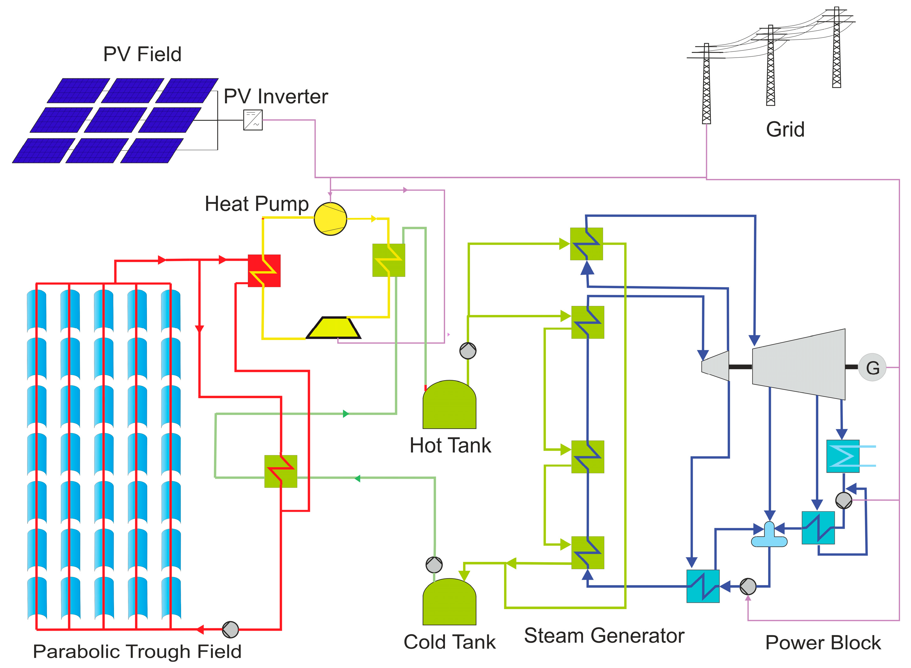
2.1. Hybrid CSP–PV Power Plant with Heat Pump

The main system analyzed in this study was a CSP–PV hybrid plant coupled with a heat pump (HP). Solar hybrid power plants that combine PV and CSP can offer economic and flexible energy solutions with high demand coverage. The CSP plant can store heat in the thermal storage during sunny periods to capitalize on the lower electricity production costs of the PV plant. The CSP solar field has a relevant electrical demand of around 10% of its nominal power, but the steam turbine cannot operate at these partial load conditions. To address this issue, the integrated PV plant can fulfill the electric demand of the CSP field. Moreover, when the PV field cannot cover the load curve of the power plant, the heat stored in the thermal energy storage (TES) can be utilized by the power block to generate electricity. Parabolic troughs with oil are the state-of-the-art for CSP, but they lack efficiency due to low temperatures. Heat pumps present an interesting option to boost this temperature, thereby enhancing the efficiency of the power block. They also have higher efficiencies than electric heaters.
There are several possible configurations for a CSP–PV system with a heat pump. Madhi et al. [9] investigated three different concepts combining parabolic trough collectors with oil as heat transfer fluid, a PV field, molten salt thermal storage, and a heat pump. In the first configuration, the molten salt was preheated by the CSP field and further heated by the HP using ambient air as the heat source. In the second configuration, the CSP field preheated the molten salt, and a heat pump boosted the temperature. The CSP field also provided the heat input to the HP. The oil–salt heat exchanger and the low-temperature side heat exchanger of the HP were connected in parallel. The third configuration also preheated the molten salt and supplied the heat for the HP booster using the CSP field. In this case, the oil–salt preheater and the low temperature side heat exchanger of the HP were connected in series. All three configurations featured an oil–salt preheater and a high temperature side heat exchanger of the HP in series. The study showed the most promising results for the second configuration due to its higher coefficient of performance (COP) and estimated round-trip efficiency from electricity to heat to electricity. This second configuration, depicted in Figure 1, was selected for this study. Furthermore, the study highlighted that the HP exhibits a low COP when utilizing ambient heat due to the substantial temperature rise it must provide. Hence, configurations where the CSP–TES heat exchanger and the heat exchanger of the HP high temperature side are placed in parallel were dismissed for this investigation. This is the case, for example, with a central receiver tower or a parabolic trough field using molten salt as the working fluid. A booster function is not possible in this case. Other configurations with thermal storage allowing for higher temperatures (e.g., particles or regenerator storage) were not considered as the cost of the heat pump materials increases significantly above 600 °C.
The system analyzed and depicted in Figure 1 consists of a parabolic trough field, a PV field, a heat pump, a two-tank molten salt thermal energy storage, and a power block. The parabolic trough collectors were chosen to take advantage of the heat pump booster with a high COP. The heat transfer fluid of the CSP field is oil, reflecting the current state of the art. The CSP field provides the heat source for the heat pump. The medium of the heat pump is air, as the results are similar to N2 (best fluid in [9]) and it is easier to obtain. The PV field supplies the heat pump with electricity. The molten solar salt storage allows for high operating temperatures, improving the efficiency of the power block and reducing the storage costs of the system. The hot tank has a temperature of 565 °C and the cold tank has a temperature of 290 °C. Figure 2 shows the model of the heat pump in EBSILON®Professional [23] with nominal temperatures for a given oil mass flow from the parabolic trough field. As also shown in Figure 1, the oil–salt (CSP–TES) heat exchanger is connected in series with the high temperature side heat exchanger of the HP and in parallel with the low temperature side heat exchanger of the HP to increase the COP of the HP. The heated oil leaves the CSP field at 393 °C. Part of the oil flow is directed to the heat exchanger with the molten salt, preheating it from the cold tank temperature of 290 °C to 383 °C. The remaining oil flow is directed to the low temperature side heat exchanger of the HP. The high temperature side heat exchanger of the HP elevates the molten salt temperature from 383 °C to the hot tank temperature of 565 °C. Figure 2 also illustrates the temperature values as well as the distribution of mass flows in each section. The HP has a COP of 2.

2.2. Operating Strategy of a Hybrid CSP–PV with Heat Pump in a Temperature Booster Configuration

The operating strategy of the system plays a fundamental role in the techno-economic analysis of the plant. Depending on this strategy, the system optimization can result in different plant designs. The objective of the operating strategy of CSP–PV hybrid systems is to produce electricity as cost-effectively as possible, with a high proportion of nighttime electricity production. The operating strategy defines when the PV system feeds electricity directly into the grid, when the electricity is used to raise the temperature of the molten salt by the heat pump, and when it is used to fulfill the auxiliary needs of the plant. The operating strategy also determines when the power block produces electricity.
During sunlight hours, the PV field produces electricity and the CSP field produces heat. How this is used for a hybrid CSP–PV system with a heat pump in a temperature booster configuration is defined in this study with the following operating strategy:
  • PV power is used in the following order of priority:
    • Auxiliary demand: initially, the auxiliary demand of the CSP solar field is met (e.g., pumps, additional heating).
    • Booster function: Subsequently, the PV field supplies electricity to the heat pump, raising the temperature of the molten salt from the outlet temperature of the oil–salt preheater (383 °C) to the nominal temperature of the hot storage tank (565 °C). This improves the efficiency of the power block (PB) and increases the thermal storage capacity.
    • Excess electricity is fed into the grid.
  • CSP heat output is used to preheat the molten salt from the cold tank temperature of 290 °C to 383 °C and supply the heat input of the heat pump (HP).
  • HP heat output is used to boost the molten salt temperature from 383 °C to the hot tank temperature of 565 °C.
  • PB generates electricity at night using heat from the thermal storage. The PB is not allowed to produce electricity during the day.
Therefore, the load curve during daytime hours is covered by the PV field, while the PB fulfills the demand during nighttime hours. The optimization of the system tends to design a PV field large enough to cover the majority of the daytime demand, after the priority use of PV power for the auxiliary demand and the booster function.

2.3. Alternative Plants Concepts for Comparison

The hybrid CSP–PV system with a heat pump was subjected to a techno-economic comparison with other technologies:
  • Hybrid CSP–PV system coupled by an electric heater (Hybrid Trough ERH) (Figure 3a):
    -
    CSP output heat is used to preheat the molten salt from the cold tank temperature of 290 °C to 383 °C.
    -
    PV power is used in the following order of priority:
    • Auxiliary demand: initially, the auxiliary demand of the CSP field is met.
    • Booster function: subsequently, the PV field supplies electricity to the ERH, raising the temperature of the molten salt from 383 °C to the nominal temperature of the hot tank of 565 °C.
    • Excess electricity is fed into the grid.
    -
    An electric heater instead of a heat pump acts as a booster, raising the temperature of the molten salt from 383 °C to the hot tank temperature of 565 °C. The ERH is connected in series with the oil–salt preheater.
    -
    There is a two-tank molten salt thermal storage.
    -
    PB generates electricity at night using heat from the thermal storage. The PB is not allowed to produce electricity during the day.
  • PV thermal power plant (PVTP) (Figure 3b): Combination of a PV field with electric heater, two-tank molten salt thermal storage and power block. There is no CSP field. The PV electricity is used to feed into the grid, cover auxiliary demand and charge the thermal storage with the electric heater. The power block uses the stored heat to generate electricity. Two different operating strategies were considered for this system. The reason for this is explained in Section 4.2.
    -
    Operating strategy 1 (OS1): The use of PV electricity to charge the thermal storage has priority over the direct grid injection. The PV electricity is first used to cover the auxiliary demand of the PB and the TES. Then, the electricity is used by the ERH to charge the thermal storage. Finally, surplus electricity is used for grid injection. The PB uses the heat from the TES to generate electricity at night. The PB is not allowed to produce electricity during the day.
    -
    Operating strategy 2 (OS2): The injection of PV electricity directly into the grid has priority over charging the thermal storage. The PV electricity is first used to cover the auxiliary demand of the PB and the TES. The electricity is then fed into the grid. Excess electricity is used by the ERH to charge the thermal storage. The PB uses the heat from the TES to generate electricity at night. The PB is not allowed to produce electricity during the day.
  • Standalone parabolic trough (Figure 3c): There is no PV system. The power block can operate during the day and night. There is a two-tank molten salt thermal storage. The heat from the CSP unit is primarily used to run the power block when it reaches the minimum required level. Excess heat or insufficient heat to run the power block are stored in the TES. If the heat provided by the CSP field is not sufficient to meet the demand, the heat stored in the TES is also used to operate the PB. System optimization tends to design the CSP field large enough so that the thermal storage is generally only discharged at night.
  • PV with battery energy storage system (PV–BESS) (Figure 3d): There is no CSP field. The PV feeds electricity into the grid during the day and the excess electricity is stored in the battery. The battery is discharged when the PV field is unable to meet the demand. System optimization tends to design the PV field large enough so that the battery storage is generally only discharged at night.

2.4. Technical Assumptions

The technical assumptions are shown in Table 1 and were made for each component of the different systems based on [1]:
The limit of electrical feed-in to the grid was set at 150 MWel for all systems, both the power block and the net power of the battery. This also avoided difficulties in the design of the photovoltaic plant. The gross power of the power block had to be set at 160 MWel to ensure the coverage of the auxiliary demand under all conditions and achieve a net output of 150 MWel. The load curve was assumed to remain constant throughout the day. Therefore, the demand was 150 MWel for both day and night for all systems. The auxiliary demands were defined as either dependent on the ambient temperature or fixed depending on the component. The connection to the grid, substations, or transmission lines were not factored into the results.

3. Materials and Methods

3.1. Simulation Tools Used

The systems were modeled and simulated using the software YACOP [24]. This is a tool for the techno-economic evaluation and optimization of energy systems on a plant scale. The tool is developed by the DLR Solar Research Institute and is currently only available for internal use. It uses mass flow-based models including temperature and pressure information to model energy flows between components as well as losses and conversion efficiencies inside the components. To evaluate the annual yield of an energy system, YACOP applies time series calculations, usually with a time fidelity of 15–60 min. To account for dynamic effects in the scope of the time fidelity, a quasi-dynamic modeling approach is used describing the availability of components depending on their operation modes in previous time steps. YACOP is designed to provide high flexibility to the user, enabling the easy exchange or addition of new components by using a modular structure. The tool is programmed in Python and presents interfaces to other programs such as EBSILON®Professional.
For this study, models based on [25] for the PV field, battery storage, and electric heater components were used. The modeling of the parabolic trough field and the thermal energy storage system is based on [26]. For the heat pump and the power block, stationary models were created in EBSILON®Professional. These models were evaluated across various operating points and integrated into YACOP as characteristic maps. The models for the parabolic trough field and the power block were extended in order to be able to map the start-up and cool-down behavior in a simplified manner. The overall system is solved in each time step of the annual yield calculation using iterative procedures. The operating strategy is integrated into the solution process and determines the distribution of the electrical and fluid flows. As a result, all electrical flows in the form of power and all fluid flows in the form of mass flow, temperature, and pressure between the components are determined at each time step. In a downstream post-processing stage, various techno-economic key performance indicators are calculated based on the results of the time step calculation.

3.2. Evaluation Criteria

The LCOE, the capacity factor (CF) and the nighttime electricity fraction were chosen for the representation of the results. The LCOE measures the lifetime cost of a system, including the cost of capital, divided by its energy production, and is very useful for comparing different technologies as it indicates the minimum constant price at which electricity must be sold to have an economically viable project, strongly depending on the financial assumptions made. Equation (1) [25] shows how the LCOE was calculated.
LCOE = Total   Investment   Costs + t = 1 t ges Annual   Running   Costs t ( 1 + r ) t t = 1 t ges Annual   Electricity   Solar t × 1 d t 1 ( 1 + r ) t ,
where r is the interest rate, t is the year within the period of use (1, 2, … tges), tges is the period of use (system life time in years) [a] and d is the yearly degradation rate.
However, the LCOE cannot be the sole metric considered when analyzing a power plant. One of the primary objectives of a hybrid system is to increase the number of hours in which electricity is produced. This can be as crucial as reducing the cost of electricity. In certain scenarios, maximizing night production may be the most desirable objective. In this study, the capacity factor and the nighttime electricity fraction were selected to reflect both aspects. The capacity factor is defined as the annual gross electricity generation divided by the net capacity times 365 (days/year) times 24 (hours/day) [27]. Given the assumption of a constant load profile in this study, the CF also represents the percentage of the load curve covered by the power plant covers throughout a year. On the other hand, the nighttime electricity fraction denotes the percentage of the plant’s electricity production occurring during nighttime hours. Each of these two parameters offers a different perspective in the techno-economic analysis. Therefore, both were used to present the results. Equation (2) [27] was utilized to calculate the CF, while Equation (3) [1] was applied to calculate the nighttime electricity fraction. Night hours were defined beforehand for each month. An hour was considered to be nighttime if the PV output on a sunny day in the middle of the month did not reach 25% of its nominal value for that hour.
Capacity   factor = annual   gross   electricity   generation net   capacity   ×   8760
Nighttime   electricity   fraction = annual   night   electricity   production total   annual   electricity   production

3.3. Parameter Variations

A variation of parameters was carried out for the simulation and optimization of the systems. For this purpose, four different storage capacities were simulated: 3 h, 6 h, 9 h and 12 h. The CSP field size, the PV field size and the nominal electric input of the heat pump and electric heater were varied in small steps to identify the optimal design in terms of resulting LCOE for each storage capacity.
The steps taken in the parametric variation for each variable defining the system are shown in Table 2.
The parameter variation produced numerous results for all the simulated configurations. To provide a simpler and more visually accessible representation of the results, the designs with the lowest LCOE for a given storage capacity were selected. Specifically, for each technology, a results curve is presented with four points representing the designs with the lowest LCOE for 3 h, 6 h, 9 h and 12 h of storage capacity. By employing this methodology, optimized system configurations with the lowest LCOE value across a wide range of capacity factors were obtained. In addition, a sensitivity analysis was conducted on the costs of the heat pump, the electric heater and the parabolic troughs.

3.4. Cost Assumptions

The cost assumptions are shown in Table 3 and were derived from the expertise gained in DLR projects [1], the relevant literature [28,29], and market research, reflecting values applicable for the year 2021. The economic situation since then has been very dynamic, influencing costs in recent years and presenting challenges in making assumptions. Particularly within the CSP field, there has been scant citable information in the literature and a limited number of projects, complicating the task of updating cost assumptions. Consequently, it was deemed appropriate to utilize the costs previously assumed in [1], providing a consistent and referenceable database. Moreover, BESS costs decreased again in 2023 and are expected to continue declining in the coming years, as shown in [30]. While this trend warrants consideration in future analyses, it was not incorporated into the current study due to the utilization of the uniform database.
Another notable challenge encountered was determining the cost of the heat pump, as this component was not studied in previous projects, and the literature data on these costs were scarce due to the limited availability of such systems in the market. Consequently, a sensitivity analysis was carried out using variable costs for the heat pump. A reference value of USD 400/kW was assumed for technology comparison purposes. For the detailed comparison with the heat pump, a cost sensitivity analysis was also performed for the electric heater, although in this case a reference value of USD 100/kW was available from previous projects [1] for the general comparison with all the other systems. Engineering, procurement and construction (EPC) surcharges were related to the capital expenditure (CAPEX) and calculated with different values for each subsystem, reflecting the varying levels of maturity of each technology. An additional operation and maintenance (O&M) cost was also allocated for the batteries to account for their replacement or addition, with the aim of ensuring a 25-year lifetime. A sensitivity analysis of the specific costs of the parabolic trough collectors was also performed to assess their influence on the results.
For the economic evaluation, the land costs were disregarded, as their influence on the LCOE was deemed negligible (assuming low cost desert sites). On the other hand, an interest rate of 5%, an operation period of 25 years and the degradation values of Table 1 were assumed.

3.5. Location of the Power Plant

The location chosen for the simulations was the Plataforma Solar Almeria (PSA) [31] in Spain. The meteorological dataset had a time resolution of one hour.
  • Annual DNI: 2207 kWh/m2
  • Annual GHI: 1860 kWh/m2
  • Average temperature: 16.6 °C
  • Latitude: 37.09 °N
  • Longitude: 2.36 °W
  • Height: 492 m

4. Results and Discussion

Firstly, the systems with a heat pump and electric heater were compared through a sensitivity analysis of the costs associated with these components. Subsequently, a comparison of all the technologies included in the study was carried out using reference costs. These results were analyzed, and finally, an additional sensitivity analysis was performed, varying the costs of the parabolic trough collectors to gain a better understanding of the results.

4.1. Comparison CSP–PV Hybrid Systems with HP and ERH

The first objective of the simulation was to compare the results of the hybrid CSP–PV plant with heat pump (HP) and the hybrid CSP–PV plant with electric resistance heater (ERH), both based on a booster setup. Given the limited availability of data in the literature regarding the costs of a heat pump with these characteristics, a sensitivity analysis of the costs of the HP and ERH was conducted initially. For this reason, costs of USD 300/kW, USD 400/kW and USD 500/kW were used for the heat pump. For the electric heater, costs of USD 70/kW, USD 100/kW and USD 150/kW were assumed for the sensitivity analysis. The results are shown in Figure 4. The solid lines show the results for the system with a heat pump, while the dashed lines show the results for the system with an electric heater. It can be seen that the system with an electric heater exhibits lower values of the LCOE for all simulated costs. The LCOE of the system with a heat pump ranges between USD 0.07/kWh and USD 0.08/kWh, depending on the storage capacity and assumed cost for the heat pump. The system with electric heater presents LCOE values between USD 0.65/kWh and USD 0.075/kWh.
Since the system with the electric heater shows lower LCOE values than the system with the heat pump, the driving factors of the higher costs when using the HP were analyzed. From a thermodynamic perspective, the heat pump configuration should be more efficient as the electricity is used with a COP of 2 instead of almost 1 in the case of the electric heater. However, the specific investment costs of the heat pump are higher and the CSP field required for the heat pump system is larger. Figure 1, Figure 2 and Figure 3a show the hybrid concepts with the heat pump and electric heater. The CSP field is responsible for increasing the temperature of the molten salts from the cold tank temperature (290 °C) to 383 °C in both systems. The booster then raises the temperature from 383 °C to the hot tank temperature (565 °C). In the case of the system with an electric heater, this temperature rise (booster function) is provided solely by the electric heater and therefore by the PV field. In the case of the system with the heat pump, the temperature boost is achieved using the heat pump with a COP of 2. Therefore, both the heat from the CSP field and the PV electricity are necessary to boost this temperature. As a result, the heat pump system requires a larger CSP field, a smaller PV field, and a lower electrical power for the heat pump compared to the electrical power of the electric heater. Table 4 and Table 5 show the size of the components of the hybrid system with the heat pump and the hybrid system with the electric heater optimized for each storage capacity. The optimization of the heat pump system results in a CSP field that is twice as large as that of the system with ERH. The PV field is, as expected, smaller in the systems with HP. The higher cost of the CSP field combined with the higher total cost of the HP leads to the higher LCOE values. The optimization also leads to the oversizing of the PV field, particularly with small storage capacities, in order to generate the cheapest electricity. On the other hand, the electric heater is slightly undersized so that more electricity is fed directly into the grid. There is also a significant undersizing of the HP so that more electricity is fed directly into the grid and the HP can operate at its nominal operating point.

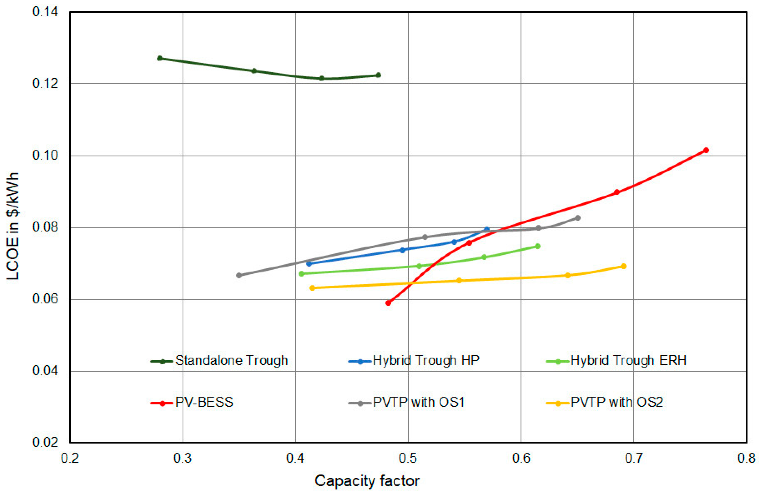
4.2. Comparison Hybrid CSP–PV Systems to Other Technology Options

The hybrid systems were compared with other solar technologies to provide a comprehensive overview of the current market technologies and their potential. The results of the simulation are shown using the capacity factor on the horizontal axis in Figure 5 and the nighttime electricity fraction in Figure 6. The reference cost assumptions from Table 3 were used for this comparison.
The standalone parabolic trough system has the highest LCOE of all the systems because it cannot benefit from the low electricity cost of a PV plant. The LCOE decreases as the capacity factor increases due to the cost-effective thermal storage and enhanced utilization of the power block. The power block is fixed at a constant nominal power, but generates more hours of electricity as the size of the thermal storage increases. The hybrid systems show a significant cost reduction compared to the standalone CSP system. The LCOE values remain relatively constant over the range studied, regardless of the capacity factor, although they increase slightly at higher capacity factors. A larger thermal storage leads to more efficient utilization, but dumping and investment costs also increase.
The PV–battery energy storage combination (PV–BESS) is the technology that achieves the lowest LCOEs for capacity factors below 50% or nighttime electricity fractions below 17% (about 4 h of storage capacity). However, its costs escalate rapidly as the capacity factor increases, due to the higher costs associated with battery storage compared to thermal storage. With a capacity factor of 60%, PV–BESS is already more expensive than hybrid systems. The difference becomes even more pronounced as the storage capacity increases.
The results for the PV thermal power plant (PVTP) depend on the operating strategy used. The two different operating strategies differ in the way the electricity generated by the PV field is utilized. Operating strategy 1 (OS1) prioritizes charging the thermal storage to ensure sufficient energy availability for nighttime production, while operating strategy 2 (OS2) prioritizes supplying the grid and only uses excess energy to charge the storage. PVTP with OS1 (thermal storage charging priority) shows higher LCOE values and nighttime fractions than OS2 (grid injection priority). However, OS2 achieves a slightly higher capacity factor. By injecting electricity directly into the grid, OS2 provides a greater quantity of electricity at a lower price. This also allows for a higher capacity factor, mainly by optimizing production during the day, and less dumping, as the thermal storage does not fill up as quickly. OS1 leads to a higher nighttime electricity fraction because electricity is initially directed towards filling the thermal storage. Consequently, OS1 necessitates a larger PV field to ensure significant amounts of electricity are fed directly into the grid. While increasing the PV field raises dumping losses when the storage is full and PV generation is constrained by grid connection capacity, the economic benefits justify this size increase with OS1 despite the higher LCOE. The OS1 thus leads to high nighttime fractions, but at the cost of higher LCOE. The system optimized with OS2 does not produce the same absolute amount of electricity during the night as the system with OS1. A larger PV field would increase this amount with OS2 but also increase the dumping losses and consequently the LCOE.
PVTP with OS1 shows higher LCOE values than the hybrid system with an electric heater and similar values to the system with a heat pump for the same capacity factors. However, the amount of electricity generated at night, both in absolute and relative terms, is much higher than for the hybrid systems. This results from the OS1 setup that clearly prioritizes storage charging and therefore operation at nighttime. PVTP with OS2 shows lower LCOE values than the hybrid systems. It is the technology with the lowest costs in this study when capacity factors above 50% are desired. The differences are not very large compared to the hybrid system with an electric heater and are probably in the order of magnitude of the accuracy of the cost assumptions. The results also indicate that the PV supplied systems offers the possibility to reach higher capacity factors at a moderate increase in LCOE which is caused by the low heat generation costs of the PV—electric heater combination. It is not possible to fully compare the operating strategy of hybrid systems and PV thermal power plants, as the systems have different components and therefore different characteristics. Initially, OS1 was assumed for the PV thermal power plant, as the priority order for the use of PV power is the same as for hybrid systems. However, the results with OS2 show a lower LCOE and higher capacity factors than hybrid systems. Therefore, the implementation of OS2 was considered pertinent for the techno-economic comparison of technologies and an interesting alternative to achieve significant nighttime electricity production.
The study is conducted for the site of Almeria with moderate DNI resource. The results may change in better CSP sites with higher DNI since the investment in CSP solar field is better utilized there. The impact of electric heater start-up times has not been considered in this study. Any significant start-up time/energy consumption would impact all systems, but especially the PVTP configuration.
Table 6 shows the size of the components of all the systems analyzed for the LCOE-optimized design with a storage of 6 h. The standalone trough presents a much larger CSP field than the hybrid systems. However, it is also the system with the smallest total area due to the higher energy density of the CSP field. PV thermal power plants show a larger PV field than PV–BESS due to the higher efficiency of the battery compared to the power block. The hybrid system with ERH requires a smaller ERH than PV thermal power plants, as this component is not the only one used to fill the thermal storage. The CSP field also contributes to filling the TES. PV thermal power plants are the largest systems due to their larger PV field. After PV–BESS, PV thermal power plants are the systems with the highest capacity factor, but they are also the ones that generate the largest absolute amount of electricity at night. PVTP with OS1 produces significantly more electricity at night than other systems.

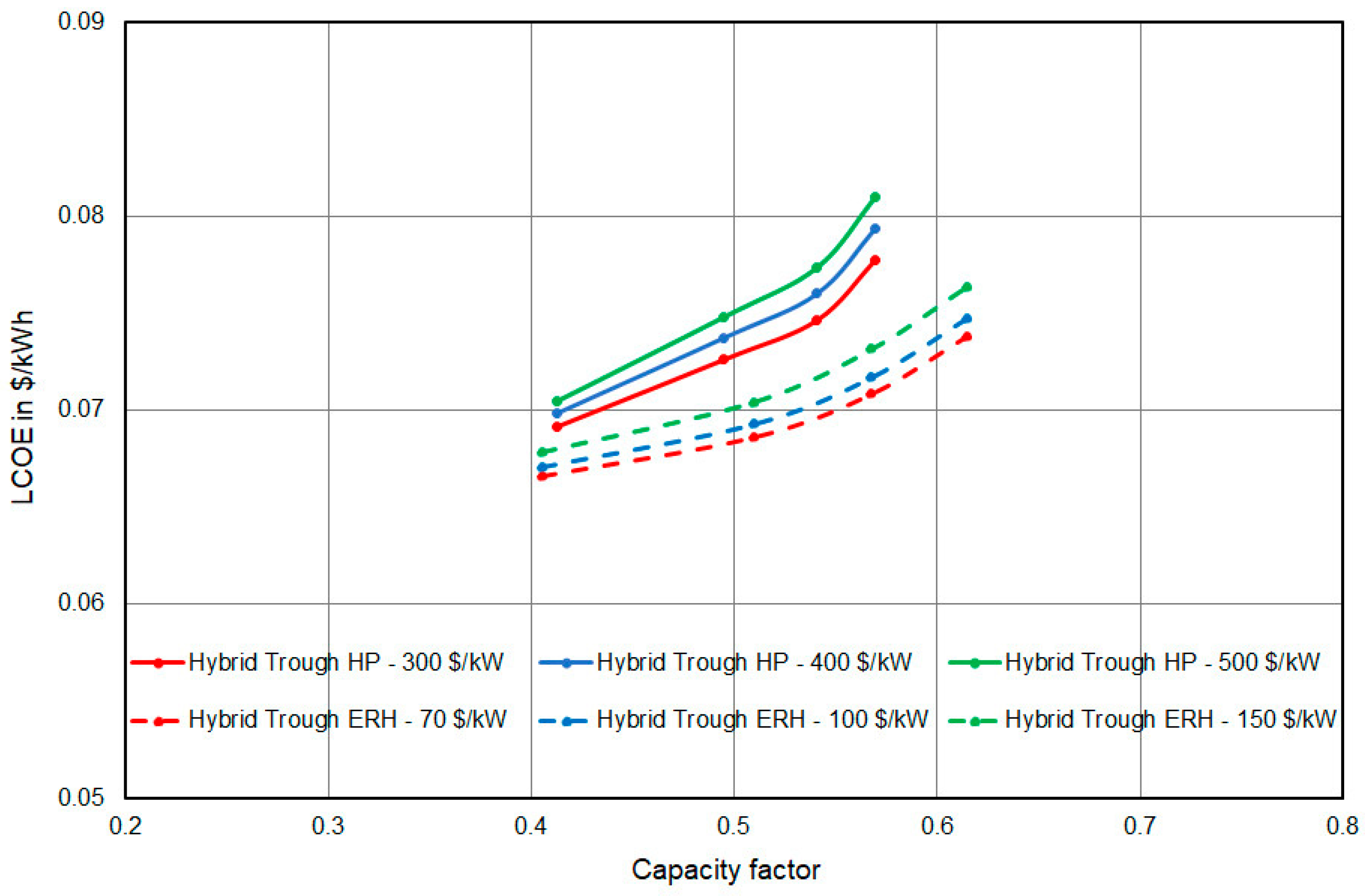
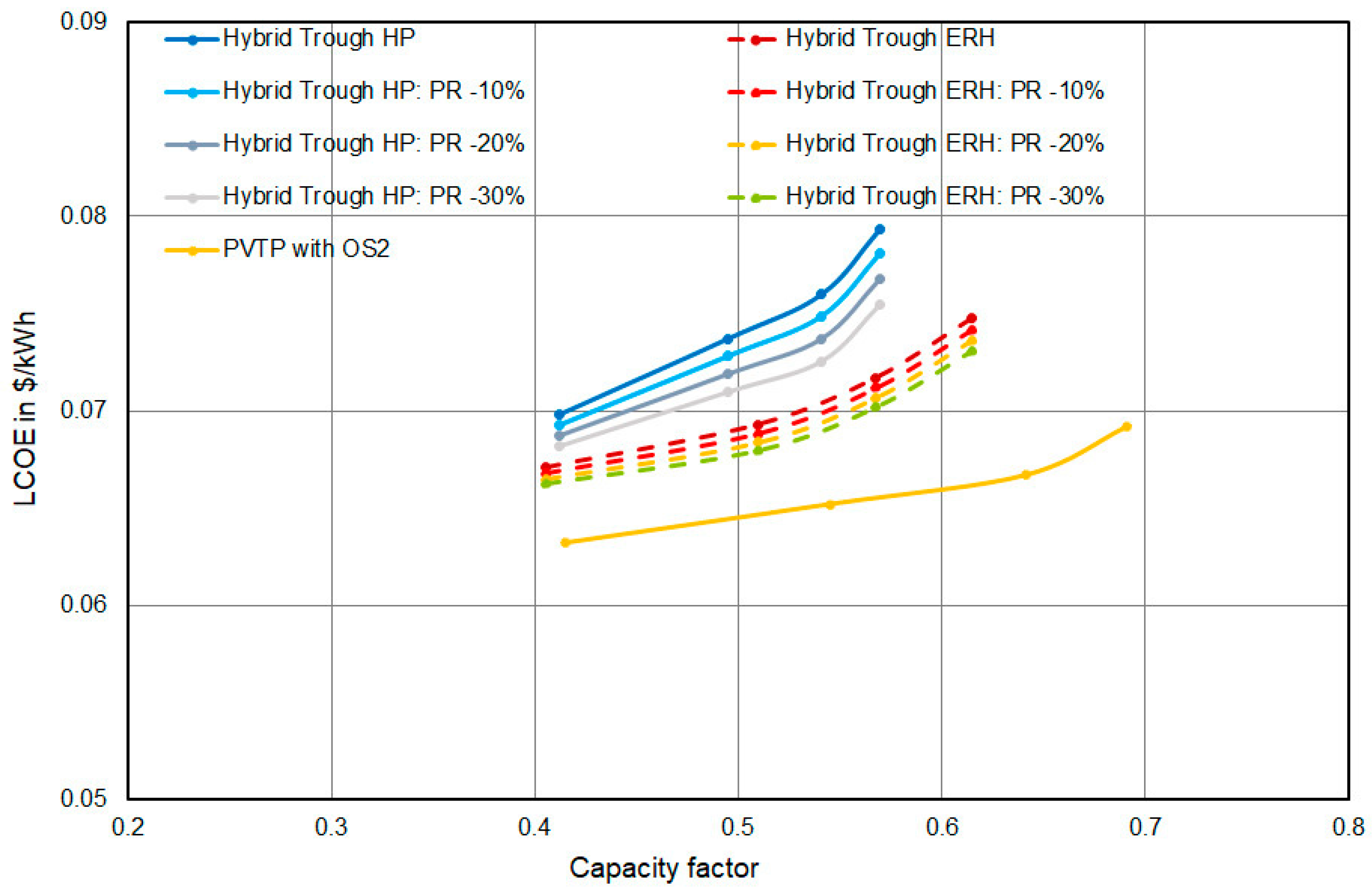
4.3. Sensitivity of HP and ERH Configurations to CSP Field Costs

The analysis of the comparison between the system with a heat pump and the system with an electric heater shows that not only the higher costs of the heat pump contribute to its higher LCOE, but also the larger size of the CSP field. A future reduction in the costs of CSP technologies could potentially narrow down the gap in LCOE between both technologies. To explore this possibility, a sensitivity analysis was conducted on the cost of parabolic trough collectors. While the costs for the heat pump and electric heater were kept at their reference values, the specific costs of parabolic trough collectors were decreased by 10%, 20%, and 30%. The design was not re-optimized. The new costs were calculated for the optimized designs with reference costs. Figure 7 shows the results of this sensitivity analysis, alongside the comparison to the PVTP with operating strategy 2. The analysis indicates that the heat pump system experiences a more substantial reduction in its LCOE compared to the electric heater system. This outcome aligns with expectations due to the larger CSP solar field size in the optimized heat pump system. However, even with a 30% reduction in the cost of the CSP solar field, the LCOE values of the hybrid system with ERH remain lower than the LCOE values of the hybrid system with HP. This supports the conclusion that the thermodynamic benefit of a heat pump can in this configuration not be translated into an economic benefit because of the large difference in CAPEX between the electric heater and the heat pump. The assumed reduction in parabolic trough costs is not sufficient to reach the same LCOE level as for the PV thermal power plant.

5. Conclusions

Hybrid CSP–PV systems are an attractive option to produce cheap and reliable electricity. The current work focusses on a deep integration concept based on a parabolic trough field with oil and an additional booster for rising the molten salt tank temperature to 565 °C. Two booster options with an electric resistance heater and a heat pump are investigated. The results in terms of LCOE are compared to alternative technologies to provide electricity during day and nighttime. The technologies considered are a parabolic trough plant, a PV–battery plant and a PV thermal power plant consisting of a PV field, an electric resistance heater, a thermal storage and power block. The LCOE of the hybrid system with a heat pump is higher than that of the hybrid system with an electric heater, even under optimistic cost assumptions for the heat pump. The higher LCOE is caused by the larger CSP field required and the higher specific costs associated with the heat pump compared to the electric resistance heater.
Our study supports the general finding that CSP–PV hybrids are an attractive option to reduce the LCOE of CSP systems. Compared to the alternative of a PV field with battery, the configurations with thermal storage and power block are significantly less costly when capacity factors of more than 50% are targeted (approximately 4 h of storage capacity).
Replacing the CSP solar field with a PV field and an electric heater turns out to be an attractive option since the LCOE can be lower. The comparison of two different operating strategies for such a configuration points out the large impact of the operation strategy, which ultimately defines whether day or nighttime production is the priority. The PV thermal power plant with grid injection priority results in the lowest LCOE values. On the other hand, the configuration with thermal storage charge priority allows for the highest electrical generation at night.
In conclusion, this study shows that CSP–PV hybrids with a thermal booster configuration using a heat pump are less attractive than thermal boosters with electric heaters. Configurations with a heat pump completely parallel to the CSP field were excluded since they appear less attractive due to low COPs and the low efficiency of the power block. The comparison with other technology options shows that the thermal power block has a clear advantage over PV–battery systems for capacity factors of more than 50%. However, replacing the CSP solar field with a PV field coupled with an electric heater can be an option, especially for sites with only moderate resources of direct normal irradiance. All results in this study are based on current cost assumptions. The evolution of costs might change some of the results in the future.

Author Contributions

Conceptualization, J.I.-L. and J.D.; methodology, J.I.-L. and J.D.; software, M.L., D.C., J.I.-L. and J.D.; validation, J.I.-L.; formal analysis, J.I.-L., J.D., T.H. and S.G.; investigation, J.I.-L. and J.D.; resources, J.I.-L. and J.D.; data curation, J.I.-L.; writing—original draft preparation, J.I.-L.; writing—review and editing, J.I.-L., J.D., T.H., M.L., S.G. and D.C.; visualization, J.I.-L., J.D., T.H. and S.G.; supervision, J.D., T.H. and S.G.; project administration, J.D.; funding acquisition, J.D. and T.H. All authors have read and agreed to the published version of the manuscript.

Funding

This research was funded by the German Federal Ministry for Economic Affairs and Climate Action, Project title: SWS-SYS—Systemsimulation und Systemanalyse für wärmebasierte Stromspeicher, Reference number 03EI3045.

Data Availability Statement

The data presented in this study are available on request from the corresponding author. The data are not publicly available due to restrictions on the disclosure of the tools used for processing parts of the data.

Acknowledgments

The authors gratefully acknowledge the funding of the work presented in this paper by the German Federal Ministry for Economic Affairs and Climate Action. The responsibility for the content is solely on the authors.

Conflicts of Interest

The authors declare no conflict of interest. The funders had no role in the design of the study; in the collection, analyses, or interpretation of data; in the writing of the manuscript; or in the decision to publish the results.

Abbreviations

BESSBattery Energy Storage System
CAPEXCapital expenditure
CFCapacity Factor
COPCoefficient of Performance
CRTCentral Receiver Tower
CSPConcentrated Solar Power
DNIDirect Normal Irradiance
EPCEngineering, Procurement and Construction
ERHElectric Resistance Heater
GHIGlobal Horizontal Irradiance
HTFHeat Transfer Fluid
HPHeat Pump
LCOELevelized Cost of Electricity
O&MOperations and Maintenance
OS1Operating Strategy 1 PV thermal power plant, thermal storage charge priority
OS2Operating Strategy 2 PV thermal power plant, grid injection priority
PBPower Block
PTParabolic Trough
PTESPumped Thermal Energy Storage
PVPhotovoltaic
PV–BESSPhotovoltaic System with Battery Energy Storage System
PVTPPV Thermal Power Plant: Photovoltaic System plus Electric Resistance Heater, Thermal Energy Storage and Power Block
TESThermal Energy Storage

References

  1. Iñigo-Labairu, J.; Dersch, J.; Schomaker, L. Integration of CSP and PV Power Plants: Investigations about Synergies by Close Coupling. Energies 2022, 15, 7103. [Google Scholar] [CrossRef]
  2. Guiliano, S.; Puppe, M.; Hirsch, T.; Schenk, H.; Moser, M.; Fichter, T.; Kern, J.; Trieb, F.; Engelhard, M.; Hurler, S.; et al. THERMVOLT Project: Systemvergleich von Solarthermischen und Photovoltaischen Kraftwerken Für die Versorgungssicherheit, Abschlussbericht (BMWI, 2014–2016). Available online: https://elib.dlr.de/119238/ (accessed on 15 March 2024).
  3. Gedle, Y.; Schmitz, M.; Gielen, H.; Schmitz, P.; Herrmann, U.; Boura, C.T.; Mahdi, Z.; Caminos, R.A.C.; Dersch, J. Analysis of an Integrated CSP-PV Hybrid Power Plant. AIP Conf. Proc. 2022, 2445, 030009. [Google Scholar] [CrossRef]
  4. Mahdi, Z.; Merige, P.; Chico Caminos, R.; Schmitz, P.; Herrmann, U.; Boura, C.T.; Schmitz, M.; Gielen, H.; Gedle, Y.; Dersch, J. Modeling the thermal behavior of solar salt in electrical resistance heaters for the application in PV-CSP hybrid power plants. AIP Conf. Proc. 2022, 2445, 030013. [Google Scholar] [CrossRef]
  5. Starke, A.; Cardemil, J.; Escobar, R.; Colle, S. Assessing the performance of hybrid CSP+PV plants in northern Chile. Sol. Energy 2016, 138, 88–97. [Google Scholar] [CrossRef]
  6. Benitez, D.; Röger, M.; Kazantzidis, A.; Al-Salaymeh, A.; Bouaichaoui, S.; Guizani, A.; Balghouthi, M. Hybrid CSP—PV Plants for Jordan, Tunisia and Algeria. Energies 2023, 16, 924. [Google Scholar] [CrossRef]
  7. Sumayli, H.; El-Leathy, A.; Danish, S.; Al-Ansary, H.; Almutairi, Z.; Al-Suhaibani, Z.; Saleh, N.S.; Saeed, R.S.; Alswaiyd, A.; Djajadiwinata, E.; et al. Integrated CSP-PV hybrid solar power plant for two cities in Saudi Arabia. Case Stud. Therm. Eng. 2023, 44, 102835. [Google Scholar] [CrossRef]
  8. McTigue, J.; Farres-Antunez, P.; White, A.; Markides, C.N.; Martinek, J.; Jorgenson, J.; Neises, T.; Mehos, M. Integrated Heat Pump Thermal Storage and Power Cycle for CSP: Final Technical Report; NREL/TP-5700-79806; National Renewable Energy Laboratory: Golden, CO, USA, 2022. Available online: https://www.nrel.gov/docs/fy22osti/79806.pdf (accessed on 15 March 2024).
  9. Mahdi, Z.; Dersch, J.; Schmitz, P.; Dieckmann, S.; Caminos, R.A.C.; Boura, C.T.; Herrmann, U.; Schwager, C.; Schmitz, M.; Gielen, H.; et al. Technical Assessment of Brayton Cycle Heat Pumps for the Integration in Hybrid PV-CSP Power Plants. AIP Conf. Proc. 2022, 2445, 030014. [Google Scholar] [CrossRef]
  10. Linares, J.; Martín-Colino, A.; Arenas, E.; Montes, M.J.; Cantizano, A.; Pérez-Domínguez, J.R. A Novel Hybrid CSP-PV Power Plant Based on Brayton Supercritical CO2 Thermal Machines. Appl. Sci. 2023, 13, 9532. [Google Scholar] [CrossRef]
  11. Mohammed bin Rashid Al Maktoum Solar Park. Available online: https://www.mbrsic.ae/en/about/mohammed-bin-rashid-al-maktoum-solar-park/ (accessed on 15 March 2024).
  12. CSP-PV Hybrid Project Noor Energy 1/DEWA IV 700MW CSP + 250MW PV CSP Project. Available online: https://solarpaces.nrel.gov/project/csp-pv-hybrid-project-noor-energy-1-dewa-iv-700mw-csp-250mw-pv/ (accessed on 15 March 2024).
  13. Cerro Dominador CSP Plant in Chile Officially Opens. Available online: https://www.acciona.com/updates/news/cerro-dominador-csp-plant-chile-officially-opens/ (accessed on 15 March 2024).
  14. Rohani, S. HybridKraft–New Technologies for Integrated CSP/PV Hybrid Power Plants (ICPH). Available online: https://www.ise.fraunhofer.de/en/research-projects/hybridkraft.html (accessed on 15 March 2024).
  15. Prenzel, M.; Bauer, T.; Kamnang, W.; Fernholz, B.; Stengler, J. Performance Testing of Two 360 kW Electric Heaters for Molten Salt. In Proceedings of the SolarPACES 2023, Sydney, Australia, 10–13 October 2023; Available online: https://elib.dlr.de/198427/ (accessed on 15 March 2024).
  16. IEA. The Future of Heat Pumps. 2022. Available online: https://www.iea.org/reports/the-future-of-heat-pumps/ (accessed on 15 March 2024).
  17. Arpagaus, C.; Bless, F.; Uhlmann, M.; Schiffmann, J.; Bertsch, S.S. High temperature heat pumps: Market overview, state of the art, research status, refrigerants, and application potentials. Energy 2018, 152, 985–1010. [Google Scholar] [CrossRef]
  18. Jesper, M.; Schlosser, F.; Pag, F. Large-scale heat pumps: Market potential and barriers, classification and estimation of efficiency. Renew. Sustain. Energy Rev. 2020, 137, 110646. [Google Scholar] [CrossRef]
  19. Finger, S.; Abu Khass, O. The DLR High Temperature Heat Pump Pilot Plants. In Proceedings of the European Heat Pump Summit, Nürnberg, Germany, 26–27 October 2021; Available online: https://elib.dlr.de/145429/ (accessed on 15 March 2024).
  20. Walden, J.V.; Bähr, M.; Glade, A.; Gollasch, J.; Tran, A.P.; Lorenz, T. Nonlinear operational optimization of an industrial power-to-heat system with a high temperature heat pump, a thermal energy storage and wind energy. Appl. Energy 2023, 344, 121247. [Google Scholar] [CrossRef]
  21. Dumont, M.; Wang, R.; Wenzke, D.; Blok, K.; Heijungs, R. The techno-economic integrability of high-temperature heat pumps for decarbonizing process heat in the food and beverages industry. Resour. Conserv. Recycl. 2023, 188, 106605. [Google Scholar] [CrossRef]
  22. Truong, B.; Bollinger, B. Repurposing Fossil-Fueled Assets for Energy Storage; Malta Inc.: Cambridge, MA, USA, 2022. [Google Scholar] [CrossRef]
  23. Iqony. EBSILON® Professional. 2023. Available online: https://www.ebsilon.com/de/ (accessed on 15 March 2024).
  24. Loevenich, M.; Cordoba, D.; Dersch, J. Yield Assessment Calculation and Optimization Program (YACOP). 2024. [Google Scholar]
  25. DLR. Greenius. 2020. Available online: http://freegreenius.dlr.de (accessed on 15 March 2024).
  26. Hirsch, T.; Mehos, M. SolarPACES Guideline for Bankable STE Yield Assessment. 2017. Available online: https://www.solarpaces.org/guideline-for-bankable-ste-yield-assessment/ (accessed on 15 March 2024).
  27. IEA. Renewables Information: Overview. Transformation. Available online: https://www.iea.org/reports/renewables-information-overview/transformation (accessed on 15 March 2024).
  28. National Renewable Energy Laboratory (NREL). Annual Technology Baseline (ATB) Cost and Performance Data for Electricity Generation Technologies [Data Set]. Available online, 2021. Available online: https://data.openei.org/submissions/4129 (accessed on 15 March 2024).
  29. Ramasamy, V.; Feldman, D.; Desai, J.; Margolis, R.U.S. Solar Photovoltaic System and Energy Storage Cost Benchmarks: Q1 2021; NREL/TP-7A40-80694; National Renewable Energy Laboratory: Golden, CO, USA, 2021. [Google Scholar]
  30. National Renewable Energy Laboratory (NREL). Annual Technology Baseline (ATB). Cost and Performance Data (Both Current and Projected) for Both Renewable and Conventional Technologies [Data Set]. 2023. Available online: https://atb.nrel.gov/electricity/2023/data (accessed on 15 March 2024).
  31. Plataforma Solar de Almería (PSA). Available online: https://www.psa.es/es/index.php (accessed on 15 March 2024).
Figure 1. Hybrid CSP–PV power plant coupled by a heat pump on booster configuration.
Energies 17 02634 g001
Figure 2. Heat balance diagram of the heat pump in EBSILON®Professional [23].
Energies 17 02634 g002
Figure 3. Alternative plants concepts for comparison: (a) Hybrid CSP–PV system boosted by an electric heater; (b) PV thermal power plant (PVTP); (c) Standalone parabolic trough; (d) PV with battery energy storage system (PV–BESS).
Energies 17 02634 g003
Figure 4. LCOE for the hybrid CSP–PV systems with heat pump (Hybrid Trough HP) and with electric heater (Hybrid Trough ERH) for different cost assumptions.
Energies 17 02634 g004
Figure 5. Comparison hybrid CSP–PV power plant coupled by a heat pump with other solar technologies using the capacity factor on the horizontal axis.
Energies 17 02634 g005
Figure 6. Comparison hybrid CSP–PV power plant coupled by a heat pump with other solar technologies using the nighttime electricity fraction on the horizontal axis.
Energies 17 02634 g006
Figure 7. Sensitivity analysis of parabolic trough collector costs on the hybrid plant configurations with electric heater and heat pump.
Energies 17 02634 g007
Table 1. Technical assumptions.
TechnologyTechnical Assumptions
Parabolic TroughCollector type: Ultimate Trough (Aperture width: 7.51 m, collector length: 246.7 m, effective mirror area: 1716 m2, HCE diameter: 8.9 cm, Nominal optical efficiency: 82.7%).
Distance between rows: 22.5 m; Distance between collectors: 0.5 m
HTF: Therminol VP-1
Nominal field outlet temperature: 393 °C
Nominal field inlet temperature: 300 °C
Degradation: 0.4% per year
PVBifacial-monocrystalline PV modules
Single-Axis Tracking Systems
DC/AC ratio: 1.3
PV panels’ nominal efficiency: 19%
PV inverter nominal efficiency: 98.6%
Degradation: 0.4% per year
Assumption: Optimized standalone PV configuration will also lead to the highest benefits in integrated hybrid plants. A representative single inverter system was designed and many of these systems were used in the hybrid plants to achieve the required nominal power.
Thermal energy storageStorage Medium: Solar Salt (60% NaNO3, 40% KNO3)
Nominal hot temperature: 565 °C (383 °C for standalone PT)
Nominal cold temperature: 290 °C
Thermal loss: 1% per day
Heat pumpNominal COP: 2.0
Medium: Air
Power blockSteam turbine with seven preheaters plus feed water storage
Dry cooling with air-cooled condenser
Gross efficiency: 46.5% (38.3% for standalone PT)
Live Steam Temperature: 553 °C (367.5 °C for standalone PT)
Turbine Inlet Pressure: 170 bar (100 bar for standalone PT)
Electric heaterHTF: Solar Salt (60% NaNO3, 40% KNO3)
Conversion efficiency: 99%
Battery energy storage systemTechnology: Lithium-Ion Nickel Manganese Cobalt
Round-trip efficiency: 85% related to heating, ventilation and air conditioning, self-discharge, battery management system, power conversion system efficiency, etc.
Lifetime (warranty period): 15 years (BESS has to be completely replaced after 15 years, the Operations and Maintenance (O&M) cost assumption includes a share to build up an O&M budget for the replacement)
Degradation: ≈2% of nominal capacity per year (lost BESS capacity must be restored by adding additional batteries on a regular basis to maintain BESS functionality, O&M cost includes a share to compensate for degradation)
Table 2. Steps and limits of the parameter variation.
TechnologyPV Field Size [MW]Storage Net Capacity [h]CSP Field Nominal Power [MW]ERH/HP Nominal Power [MW]
Hybrid trough HP150–600 (50 MW step)3–12 (3 h step)42–284 (22 MW step)30–155 (variable step)
Hybrid trough ERH150–650 (50 MW step)3–12 (3 h step)20–196 (22 MW step)45–405 (variable step)
Standalone trough-3–12 (3 h step)650–1850 (100 MW step)-
PV–BESS150–525 (25 MW step)3–12 (3 h step)--
PVTP150–750 (50 MW step)3–12 (3 h step)-5–600 (variable step)
Table 3. Costs assumptions.
TechnologyComponentValue 2021Unit
PTSolar field (reference cost)202USD/m2
Solar field (sensitivity analysis costs)141, 162, 182, 202USD/m2
Thermal storage38USD/kWhth
Power block930USD/kWel
EPC0.2of CAPEX
O&M0.015of CAPEX
PV systemInverter53USD/kWac
PV field454USD/kWdc
EPC0.1of CAPEX
O&M0.005of CAPEX
HPCost per kWel (reference cost)400USD/kWel
Cost per kWel (sensitivity analysis costs)300, 400, 500USD/kWel
EPC0.2of CAPEX
O&M0.01of CAPEX
ERHCost per kWel (reference cost)100USD/kWel
Cost per kWel (sensitivity analysis costs)70, 100, 150USD/kWel
EPC0.2of CAPEX
O&M0.01of CAPEX
BESSCost per power245USD/kWel
Cost per energy capacity246USD/kWhel
EPC0.235of CAPEX
O&M0.045of CAPEX
Table 4. Optimized design of a hybrid CSP–PV power plant with heat pump for different storage capacities.
Storage Capacity Hybrid CSP–PV Power Plant with HP (h)3 h6 h9 h12 h
TES capacity (MWhth)1033206630994132
CSP field nominal output (MWth)87174239283
PV field nominal output (MWac)250300300300
HP nominal power (MWel)367297122
Electricity generation (GWh/a)541650711748
LCOE (USD/kWh)0.0690.0740.0760.079
Capacity factor (%)41495457
Table 5. Optimized design of a hybrid CSP–PV power plant with electric heater for different storage capacities.
Storage Capacity Hybrid CSP–PV Power Plant with ERH (h)3 h6 h9 h12 h
TES capacity (MWhth)1033206630994132
CSP field nominal output (MWth)4387108130
PV field nominal output (MWac)250350400450
ERH nominal power (MWel)80150215260
Electricity generation (GWh/a)532670746807
LCOE (USD/kWh)0.0670.0690.0720.075
Capacity factor (%)41515761
Table 6. Optimized design of all the systems for a 6 h storage capacity.
TechnologyHybrid Trough HPHybrid Trough ERHStandalone TroughPV–BESSPVTP
OS1
PVTP
OS2
Storage capacity (h)666666
TES capacity (MWhth)206620662380-20662066
BESS capacity (MWhel)---900--
CSP field aperture (km2)0.270.141.5---
CSP field nominal output (MWth)17487978---
PV field module area (km2)2.12.4-2.13.42.7
PV field nominal output (MWac)300350-300500400
ERH nominal power (MWel)-150--200200
HP nominal power (MWel)72-----
PB nominal output (MWel)160160160-160160
Total land area (km2)6.97.45.85.99.87.8
Electricity generation (GWh/a)650670477727676716
Night Elec. generation (GWh/a)136143120177259169
LCOE (USD/kWh)0.0740.0690.1240.0760.0770.065
Capacity factor (%)495136555154
Nighttime electricity fraction0.210.210.250.240.380.24
Disclaimer/Publisher’s Note: The statements, opinions and data contained in all publications are solely those of the individual author(s) and contributor(s) and not of MDPI and/or the editor(s). MDPI and/or the editor(s) disclaim responsibility for any injury to people or property resulting from any ideas, methods, instructions or products referred to in the content.

