Abstract
In the existing literature, direct torque control (DTC) by synthesizing virtual vectors can effectively suppress low-order harmonic currents under the single open-phase fault (OPF) of the five-phase permanent magnet synchronous motor (PMSM), but the sectors and the look-up tables need to be redesigned, which makes the control process more complicated. In order to solve this problem, an indirect correction method of virtual vectors is proposed, and the amplitudes of the virtual vectors are maximized. The fault-tolerant DTC strategy under the OPF ensures that there is no need to re-divide the sectors under the fault. And the selection rules of the look-up tables are consistent with the healthy operation. The difference is that the amplitudes of ten virtual vectors in the faulty operation are reduced, which simplifies the control process and is easy to implement. Finally, the correctness and effectiveness of the proposed control strategy were verified by experiments.
1. Introduction
In recent years, multiphase PMSMs have received extensive attention from industry and academia. Compared with traditional three-phase motors, multiphase motors have the advantages of low-voltage high power, low torque pulsation, and high reliability. They have good application prospects in the fields of aerospace, ship propulsion, and wind power generation [1,2,3,4,5]. The good fault-tolerant ability is a significant advantage for multiphase motors. Most open-circuit and short-circuit faults in multiphase machine drive systems can be converted into the OPF. Therefore, the research of fault-tolerant control strategies for multiphase machines is mainly focused on the OPF. There is no need to change any hardware and only the need to select an appropriate fault-tolerant control strategy to derate and continue to run when a single OPF has occurred. Hence, shutdown or system reconfiguration can be avoided [6,7]. At present, the common control strategies for multiphase motors include field-oriented control (FOC) [8,9,10,11], model predictive control (MPC) [12,13,14,15], and direct torque control (DTC) [16,17,18,19,20,21,22,23,24]. Among them, DTC has the advantages of simple structure, low sensitivity to motor parameters, and fast torque response. Thus, it is widely researched for multiphase motor drive systems.
In order to suppress low-order harmonic currents and reduce output torque ripple when DTC is used in the healthy operation of multiphase machines, the concept of virtual vectors are proposed in many studies [18,19], i.e., synthesizing basic voltage vectors into a new virtual voltage vector during the sampling period, and the average amplitudes of virtual vectors are zero in the harmonic subspace. The virtual vectors need to be reconstructed when an OPF occurs in the multiphase motor drive system. A fault-tolerant DTC strategy for five-phase induction motor under the single-OPF condition was proposed in [20]. The ten virtual vectors during the healthy operation were transformed into eight virtual vectors during the faulty operation, and the sectors were divided into eight. The look-up table was reconstructed under the faulty operation. In order to reduce the torque ripple and the third harmonic current caused by the single OPF of the five-phase PMSM, a fault-tolerant control strategy considering the third harmonic suppression was proposed in [21]. According to the effect of the virtual vectors in different sectors on the torque and flux linkage, the look-up tables under healthy and faulty operation were established, respectively. A DTC method for a five-phase induction motor during low-speed operation was proposed in [22], and its low-speed performance was improved by deriving a new look-up table. In [23], eight virtual voltage vectors were synthesized from fundamental wave subspace under the single OPF of the five-phase induction motor. The DTC based on virtual vectors was compared with rotor field oriented control, and the DTC could reduce the amount of calculation and showed strong robustness. To eliminate the stator harmonic current under the single OPF of the five-phase induction motor, a DTC strategy with an improved look-up table was proposed in [24]. The influence of virtual voltage vectors on torque and flux response under different speed and load conditions was analyzed. The virtual vectors have also been applied to the space vector pulse width modulation (SVPWM) [25] and predictive current control [26,27] of the multiphase motor. However, after the OPF of multiphase motors, there is a common problem that the spatial phases of virtual vectors are changed [20,23,24]. Therefore, it is necessary to redesign the stator flux partitions and look-up tables, which makes the control process more complicated.
In order to solve the above problems in fault-tolerant DTC, an indirect correction method for virtual vectors under the OPF of the five-phase motor is herein proposed. And a fault-tolerant DTC strategy based on virtual vectors without redesigning sectors and look-up tables is constructed. The paper is organized as follows. In Section 2, the voltage vectors distributions of the five-phase PMSM in healthy and faulty operation are introduced. The DTC strategy based on virtual voltage vectors in the healthy operation is introduced in Section 3. Next, an indirect correction method of virtual vector with the A phase OPF is proposed in Section 4. The experimental results are presented in Section 5. Finally, the conclusions are presented in Section 6.
2. Voltage Vectors Distribution of Five-Phase PMSM
2.1. Voltage Vectors Distribution in the Healthy Operation
According to the vector space decomposition modeling theory, the static transformation matrix of five-phase PMSM can be expressed as follows:
where γ = 2π/5. The first and second rows correspond to the α1-β1 subspace and participate in the electromechanical energy conversion. The third and fourth rows correspond to the α3-β3 subspace and do not participate in the electromechanical energy conversion. The last row is zero sequence component, which is always zero.
The voltages in the natural frame [A-B-C-D-E] are transformed into the static frame [α1-β1-α3-β3-o] by the static transformation matrix (1), and the voltages can be further expressed as follows:
where UA, UB, UC, UD, and UE are phase voltages of the five-phase PMSM. Uα1, Uβ1, Uα3, Uβ3, and Uo are the voltage components in the static frame.
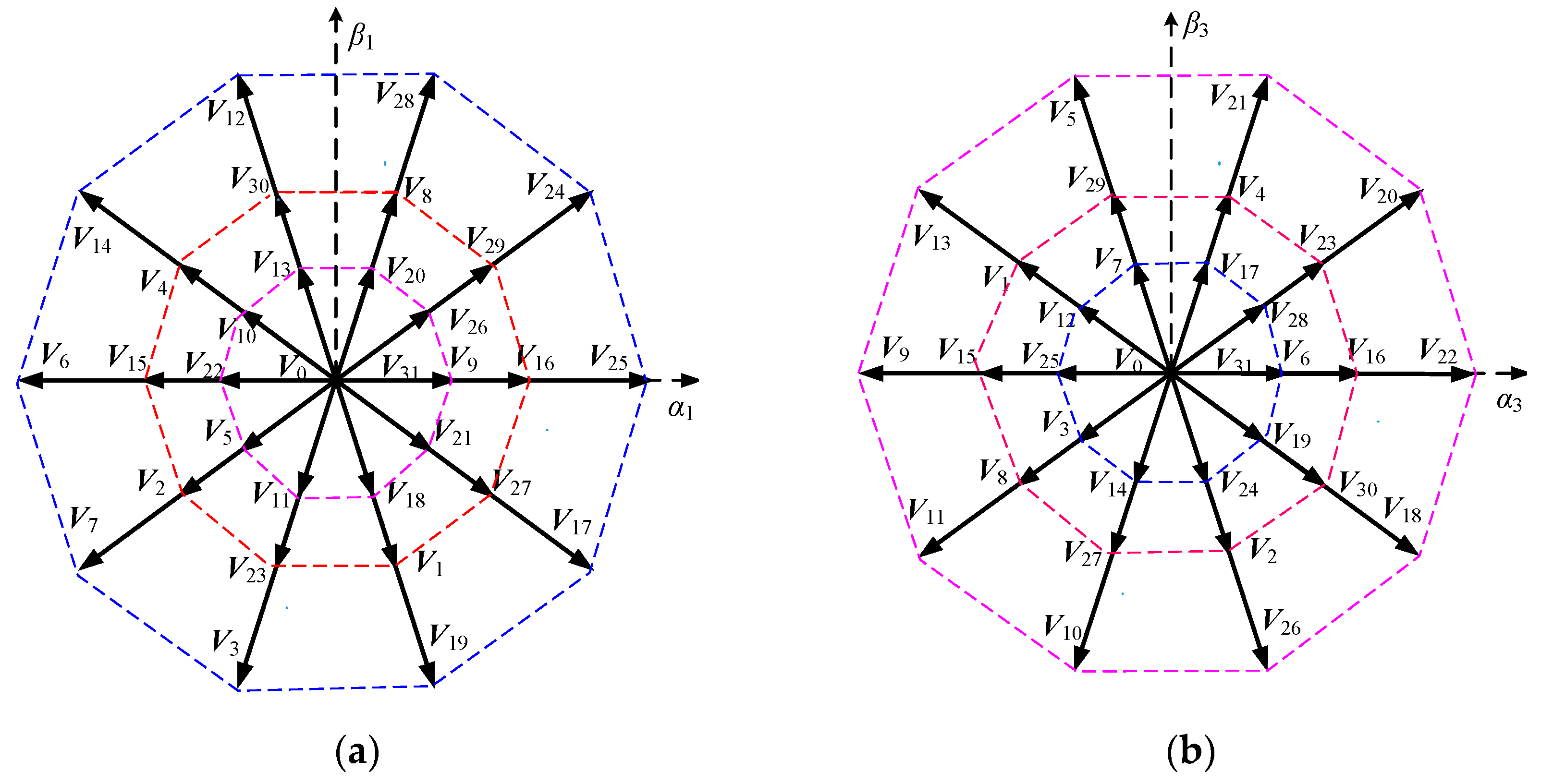
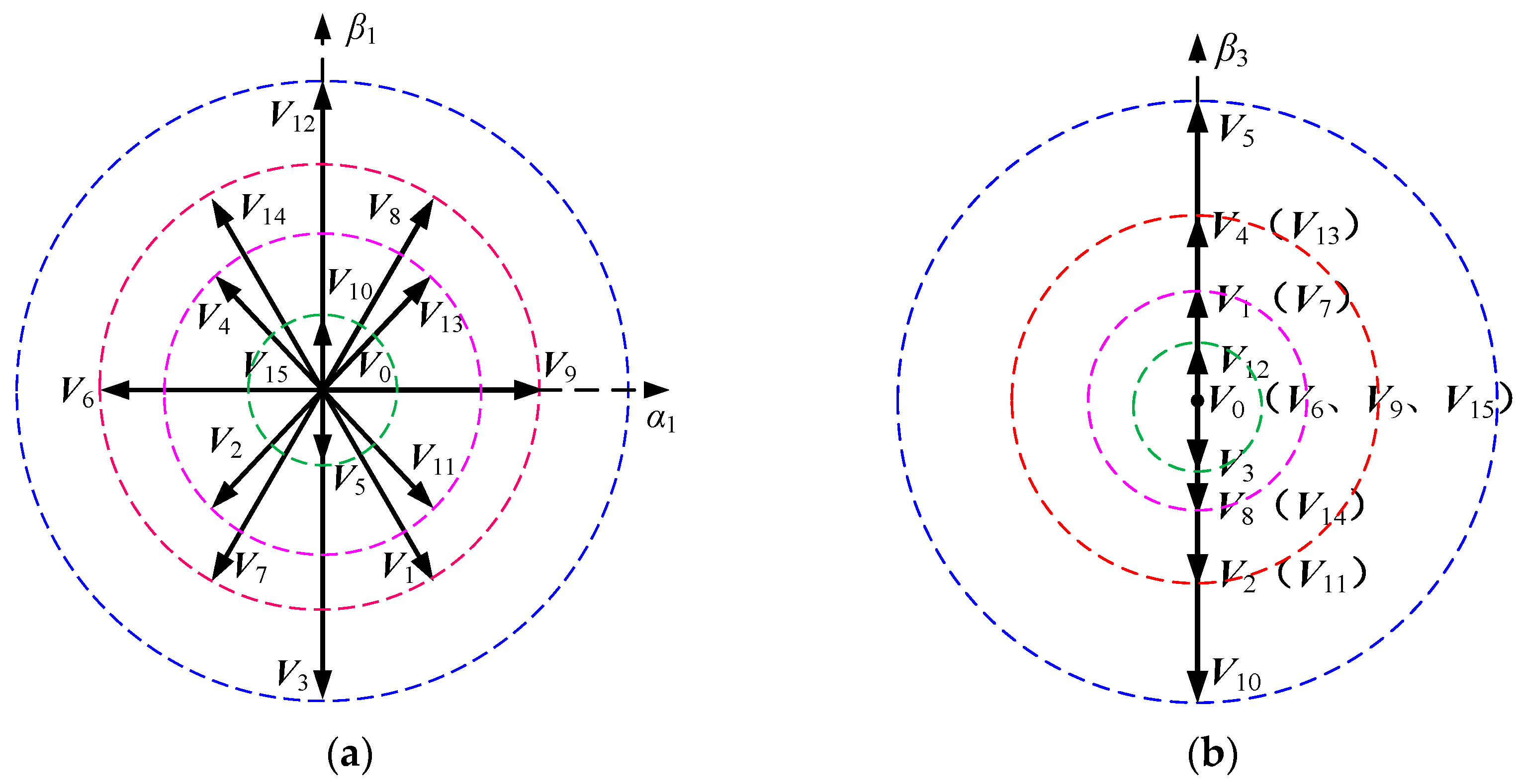
The voltage vectors are mapped to α1-β1 and α3-β3 subspaces, as shown in Figure 1. Each subspace contains 30 basic vectors and two zero vectors (V0 and V31). Basic vectors can be divided into large vectors VL, medium vectors VM, and small vectors VS according to the amplitudes of basic vectors, and the amplitudes are 0.6472Udc, 0.4Udc, and 0.2472Udc, respectively.
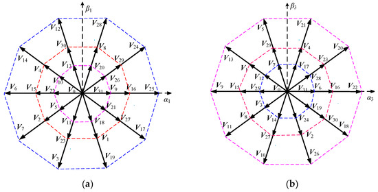
Figure 1.
The distribution of voltage vectors in the healthy operation: (a) α1-β1 subspace; (b) α3-β3 subspace.
2.2. Voltage Vectors Distribution under the Single Open-Phase Fault
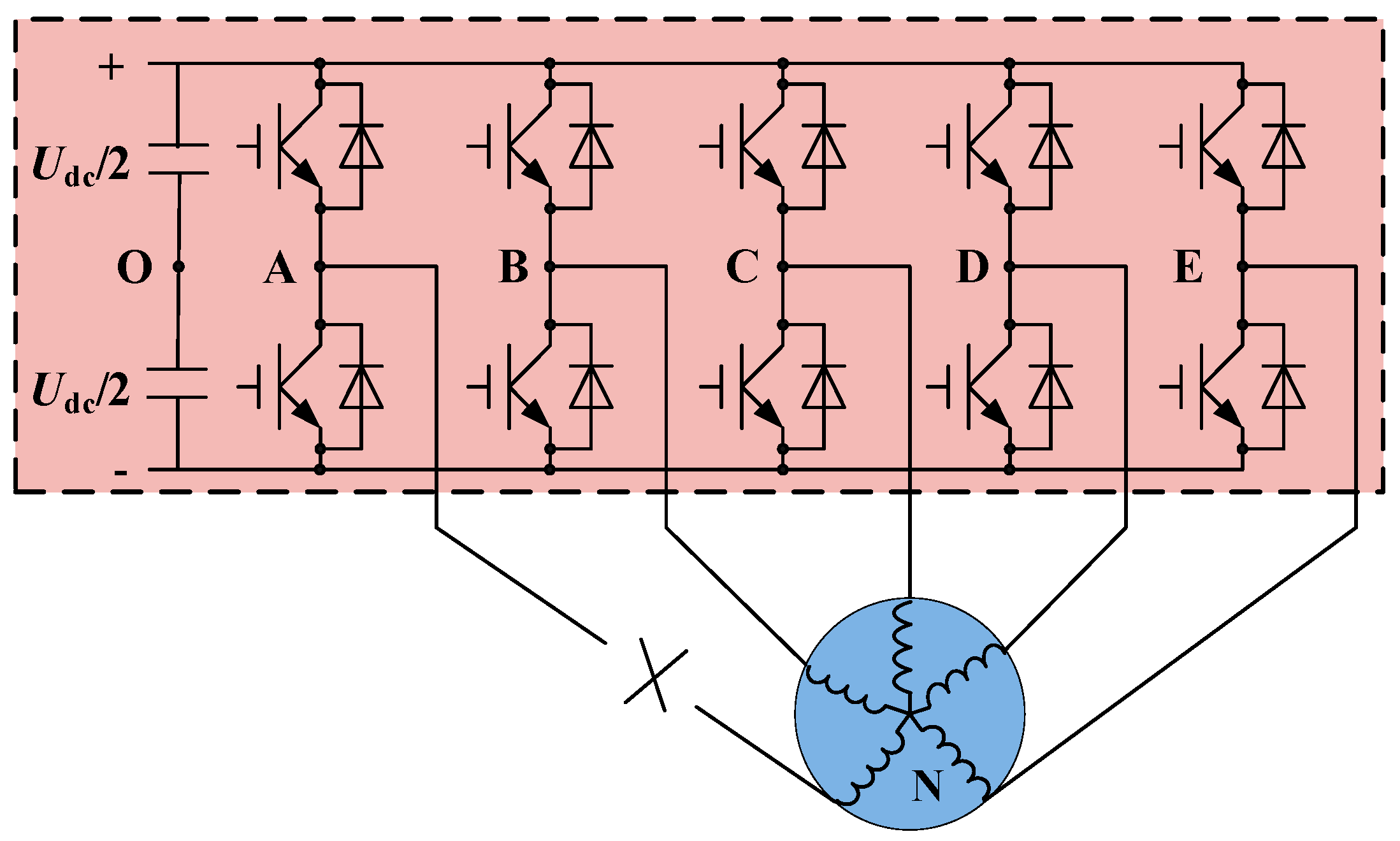
Taking the A phase OPF as example, and the main circuit topology of the five-phase PMSM drive system is shown in Figure 2.
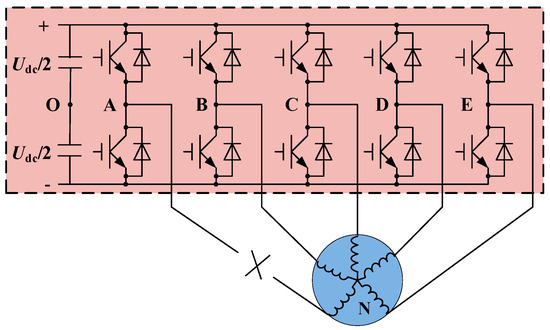
Figure 2.
Main circuit topology of the five-phase PMSM with the A phase OPF.
When the A phase OPF occurs, the static transformation matrix in the healthy operation is no longer applicable, and the reconstructed reduced-order static transform matrix can be expressed as follows:
where e0 = 0.25, and e0 is the correction coefficient.
The voltages in the natural frame [B-C-D-E] are transformed into the static frame [α1-β1-β3-o] by the reduced-order static transformation matrix, and the voltage can be expressed as given below:
Under the A phase OPF, the voltage vectors’ distribution in α1-β1 subspace and β3 pulse subspace is shown in Figure 3. Each subspace contains fourteen basic vectors and two zero vectors (V0 and V15). The amplitude and phase angle of each voltage vector in the α1-β1 subspace and β3 pulse subspace are shown in Table 1.
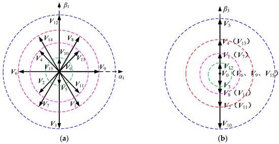
Figure 3.
The voltage vectors distribution under with the A phase OPF: (a) α1-β1 subspace; (b) β3 pulse subspace.

Table 1.
The amplitude and phase angle of each voltage vector in the α1-β1 subspace and β3 pulse subspace with the A phase OPF.
3. The DTC Strategy Based on Virtual Voltage Vectors in Healthy Operation
It can be seen from Figure 1 that the amplitudes of the basic voltage vectors in the α3-β3 subspace are not zero in the healthy operation of the five-phase PMSM. Because the harmonic impedance of the α3-β3 subspace is only constituted with the stator resistance and the leakage inductance, a very low harmonic voltage can generate large harmonic currents, which can increase the system loss and damage the motor. Therefore, the voltage vectors need to be corrected. The large and medium vectors in the same direction in the α1-β1 subspace correspond to the small and medium vectors in the opposite direction in the α3-β3 subspace. Therefore, as long as the action time of the large and medium vectors in the α1-β1 subspace are in inverse proportion to the amplitudes of the small and medium vectors in a pulse width modulation (PWM) control period Ts, it can be ensured that the synthesized voltage vector in the α3-β3 subspace is zero.
The new vectors synthesized are defined as the virtual vectors VVn (n = 1~10). The control period is Ts. It is assumed that the action time of the large vector VL is λTs, and the action time of the medium vector VM is (1 − λ)Ts. The amplitude of the synthesized virtual vector in the α1-β1 subspace is |Vα1-β1|, and the amplitude in the α3-β3 subspace is |Vα3-β3|. In a control period Ts, it is obtained by the volt-second balance principle:
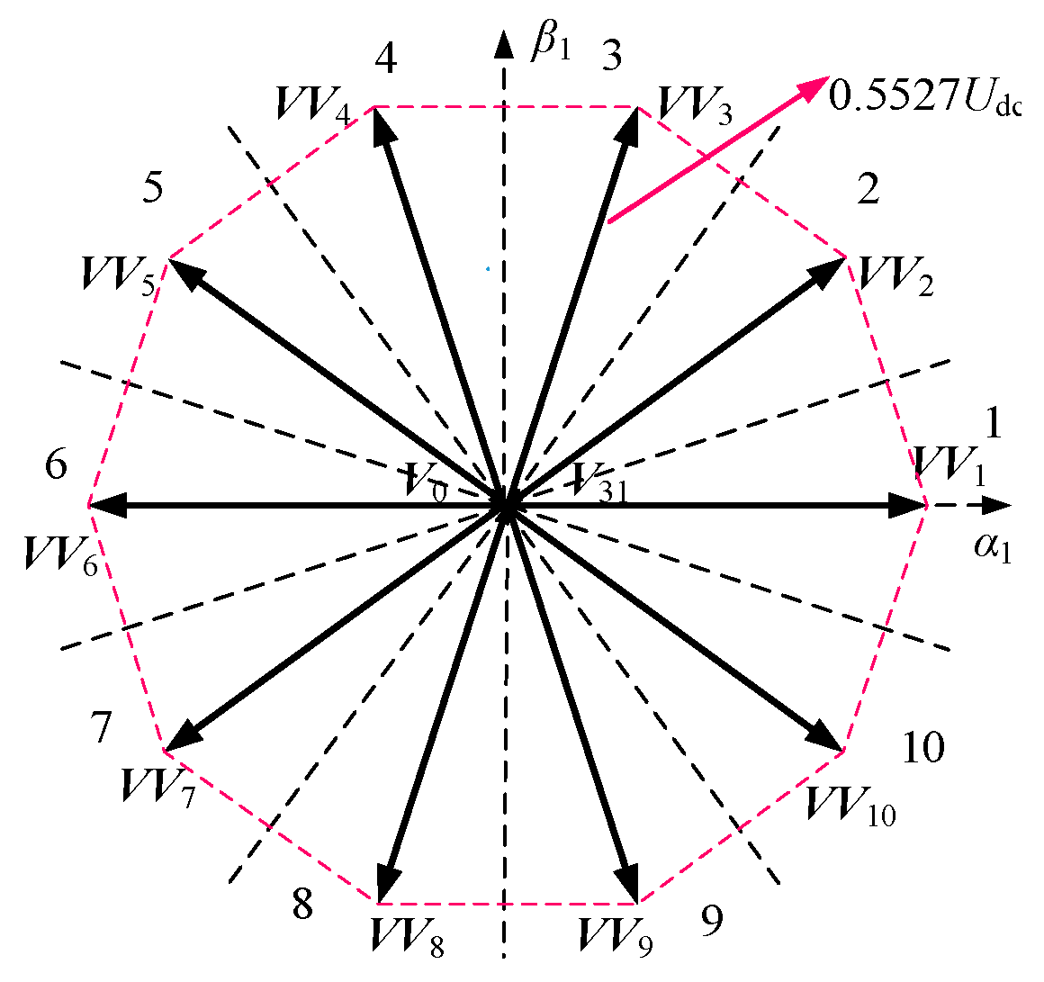
Setting |Vα3-β3| = 0, λ = 0.618 and |Vα1-β1| = (/5)Udc = 0.5527Udc can then be obtained. Ten virtual vectors are obtained from the above principles, and the α1-β1 subspace is divided into ten sectors, as shown in Figure 4.
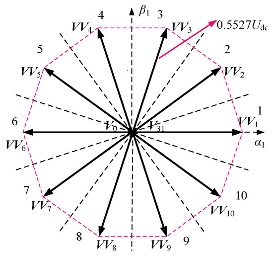
Figure 4.
The virtual vectors distribution of α1-β1 subspace in the healthy operation.
According to the effect of the radial and tangential components of the virtual vectors in different sectors on the torque and flux linkage, the voltage vector look-up table under the healthy operation of the five-phase PMSM is obtained, as shown in Table 2.
Table 2.
Voltage vector look-up table in the healthy operation.
4. Indirect Correction Method of Virtual Vectors with Single Open-Phase Fault
4.1. Equal-Amplitude Virtual Vectors
The number of voltage vectors is changed from 32 to 16 when a single OPF occurs in the five-phase PMSM, and thus, the virtual vector after the OPF needs to be re-corrected. As shown in Figure 3, the voltage vector amplitudes no longer meet the specific proportional relationship after the A phase OPF, and the spatial distribution is no longer uniform. Thus, it is difficult to adopt the method of direct synthesis that is used in the healthy operation for virtual vector correction. An indirect virtual vector correction method is proposed in this paper.
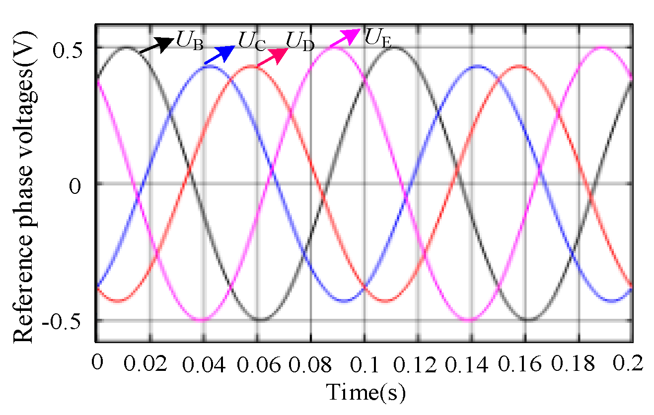
To ensure that the synthesized voltage vectors in the β3 pulse subspace are zero under the A phase OPF, the reference voltage V* = [U*α1 U*β1 U*β3]T can be expressed as V* = [μcosθ μsinθ 0]T, where μ is the amplitude of the reference voltage in the α1-β1 subspace, and θ is the angle between the reference voltage vector and the α1-axis. Since the zero sequence voltage is no longer injected after the single OPF, the phase voltage is equal to the modulation voltage (voltage between inverter output and DC bus voltage midpoint, such as UAO in Figure 2), so the amplitudes of phase voltages need to be less than 0.5Udc. The phase voltage reference values can be obtained by the inverse transformation of the reconstructed reduced-order static transform (4). The waveform of the remaining reference phase voltages when the linear modulation ratio m = 0.3406 is shown in Figure 5. It can be seen that the maximum amplitude of the corresponding reference phase voltages is 0.5Udc. Therefore, the 0.3406Udc amplitude voltage vectors can be synthesized in α1-β1 subspace at any phase angle, ensuring that the synthesized voltage vectors in the β3 pulse subspace are zero.
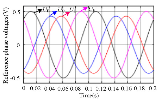
Figure 5.
The waveform of the remaining reference phase voltages when the linear modulation ratio m = 0.3406.
In order to facilitate the implementation, it is assumed that the direction of virtual vectors under the A phase OPF is consistent with that under the healthy operation. Taking the virtual voltage vector as an example, μ = 0.3406Udc, and θ = π/5. The reference voltage V* can be expressed as follows:
The phase voltage reference values can be obtained by the inverse transformation of (4). UB, UC, UD, and UE are 0.4985Udc, −0.1904Udc, −0.4257Udc, and 0.1177Udc, respectively. Because the zero sequence voltage is no longer injected after the single OPF, the phase voltage is equal to the modulation voltage. The relationship between the modulation voltages of remaining phases and the phase duty cycles under the single OPF can be written as given below:
where Ux* stands for the modulation voltages of remaining phases, and Dx is the duty cycle of each phase. X stands for the phase B, C, D, or E.
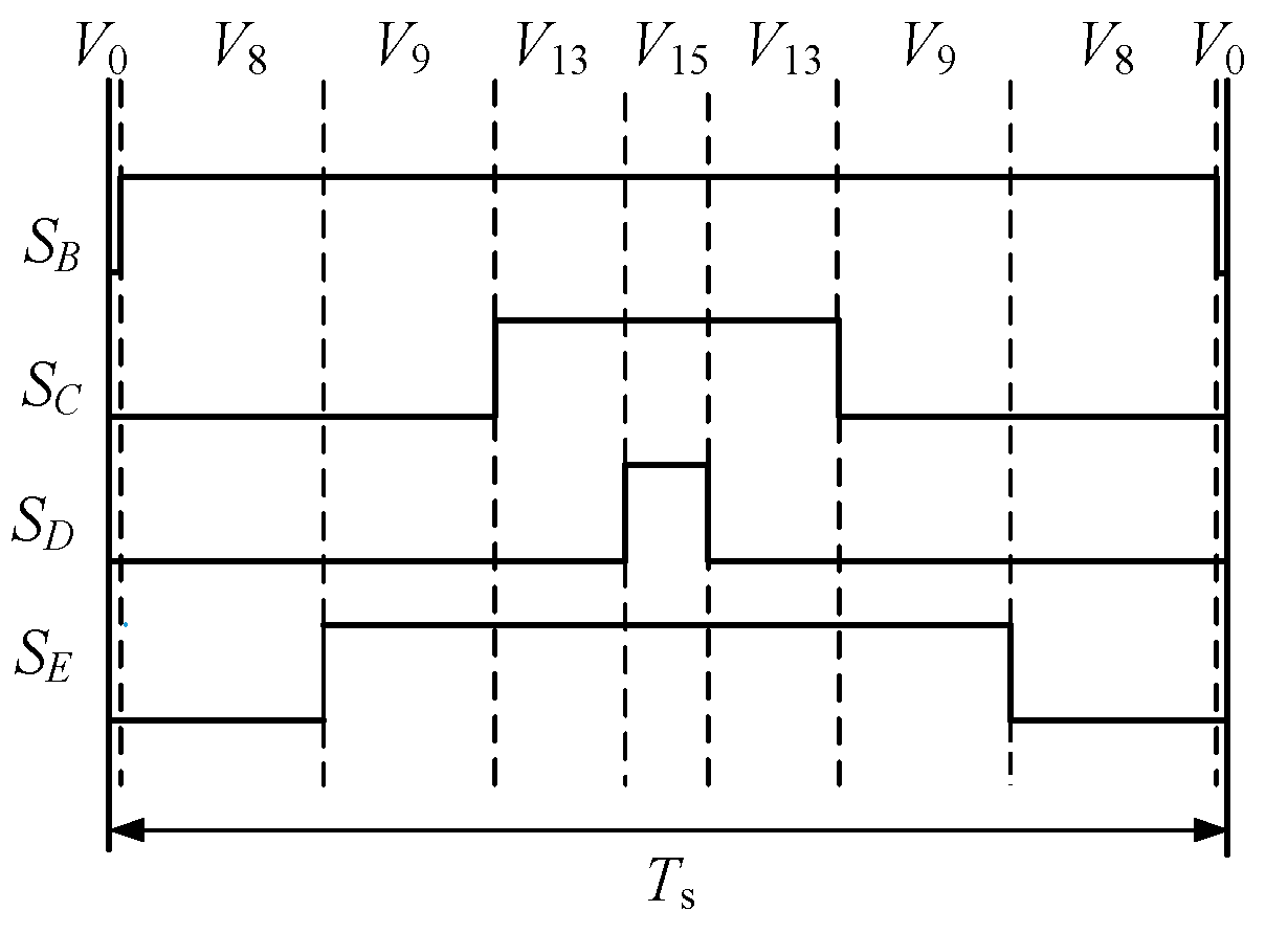
The duty cycle of each remaining phase with the phase A OPF can be obtained by the expression (7). DB, DC, DD, and DE are 0.9985, 0.3096, 0.0743, and 0.6177, respectively. Then, the PWM waveform corresponding to the virtual vector is shown in Figure 6.

Figure 6.
PWM waveform of virtual vector .
It can be seen from Figure 6 that is synthesized by three basic vectors (V8, V9, and V13) and two zero vectors (V0 and V15), and the proportions of voltage vectors are 0.3808, 0.3081, 0.2353, 0.0015, and 0.0743, respectively. The voltage vectors and their proportions corresponding to the ten corrected virtual vectors after the phase A OPF can be obtained by using the same method, as shown in Table 3. It can be seen that the virtual vectors and only use one basic voltage vector because the voltage vectors V9 and V6 do not generate voltage components in the β3 pulse subspace.
Table 3.
The voltage vectors and their proportions corresponding to the same amplitude virtual vectors after the A phase OPF.
4.2. Maximum Amplitude Virtual Vectors
It can be seen from Table 3 that all the voltage vectors corresponding to the ten virtual vectors contain a certain proportion of zero vectors (V0 and V15). The existence of the zero vectors indicates that the system cannot achieve the maximum DC bus voltage utilization. Thus, in order to further improve the DC bus voltage utilization, the action time of the zero vectors are allocated to the basic vectors according to the corresponding proportions, which will increase the action time of basic vectors. Taking the virtual vector as an example, the same amplitude virtual vectors are synthesized by three basic vectors(V8, V9, and V13) and two zero vectors (V0 and V15), and the proportions of voltage vectors are 0.3808, 0.3081, 0.2353, 0.0015, and 0.0743. Defining D0 is the duty cycle of zero vectors (V0 and V15), and D0 = 0.0758 in . The proportions of V8, V9, and V13 allocated by D0 are 0.0312, 0.0253, and 0.0193, respectively. By this way, the maximum amplitude virtual vectors can be obtained, which are synthesized only by the three basic vectors V8, V9, and V13, and the proportions of three voltage vectors are 0.4120, 0.3334, and 0.2546, respectively. By adopting this method, the amplitudes of virtual vectors can be maximized, and the following expression can be obtained:
where |Vmax| stands for the maximum amplitude of the virtual vector. D0 is the duty cycle of zero vectors (V0 and V15).
Taking the virtual vector as an example, D0 = 0.0758, and then, |Vmax| = 0.3685Udc.
The maximum amplitudes of the other nine virtual vectors are obtained by using the same method. Finally, the voltage vectors and their proportions corresponding to the maximum amplitude virtual vectors after the A phase OPF are shown in Table 4.
Table 4.
The voltage vectors and their proportions corresponding to the maximum amplitude virtual vectors after the A phase OPF.
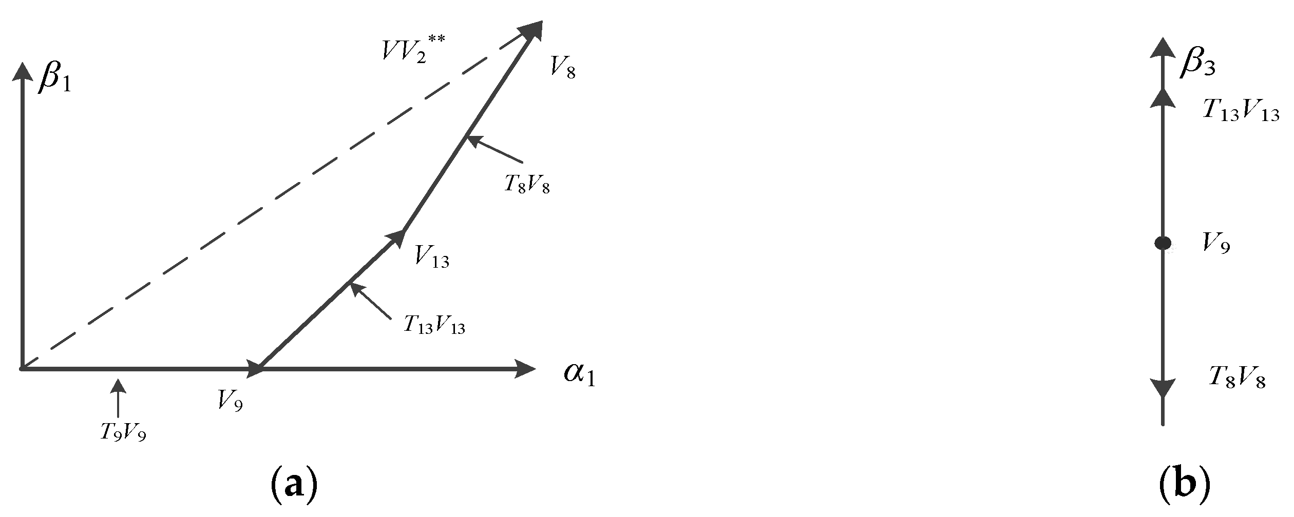
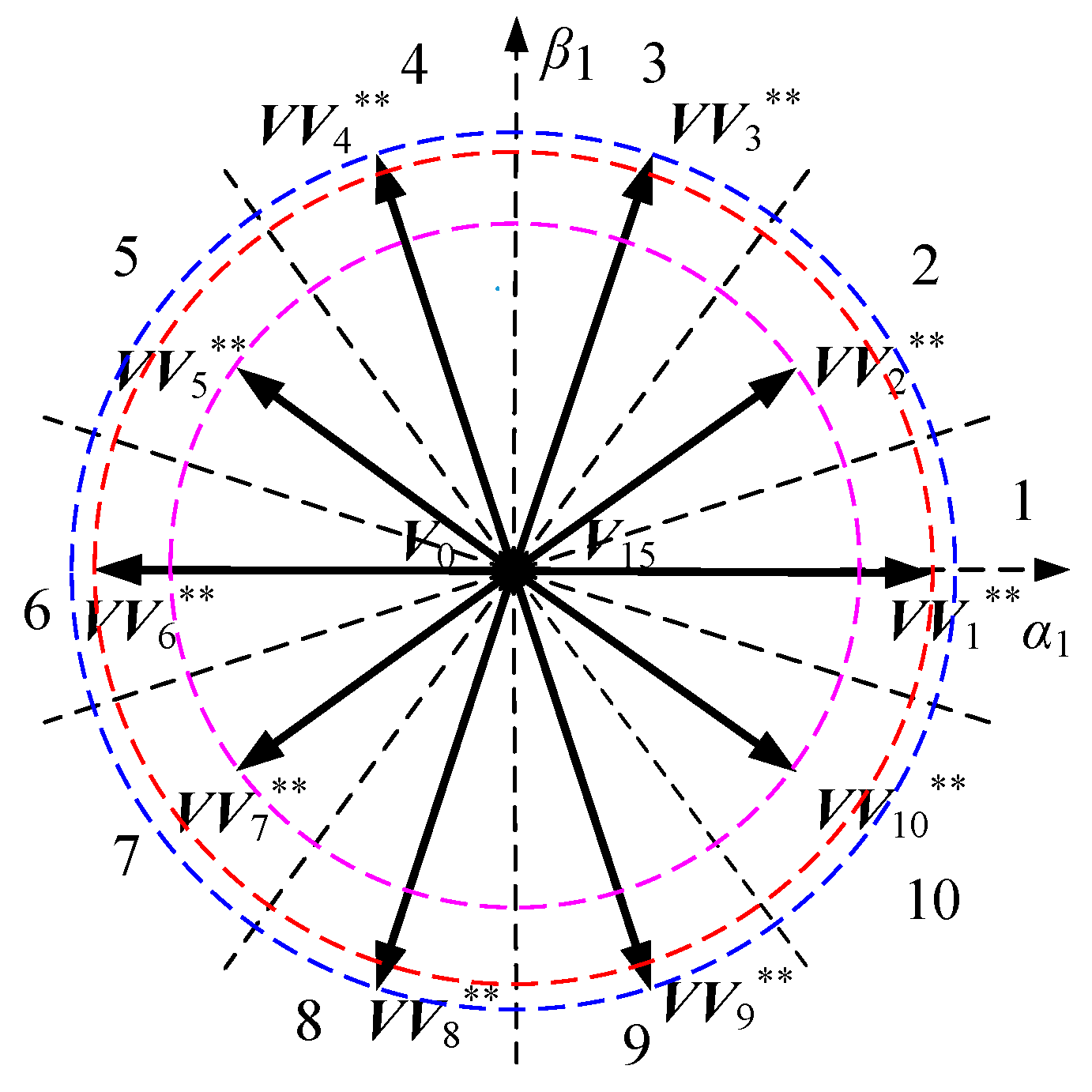
Taking the maximum amplitude virtual vector as an example, the synthesis processes of in the α1-β1 subspace and β3 pulse subspace are shown in Figure 7. Moreover, when the A phase OPF occurs in the five-phase PMSM drive system, the distribution diagram of ten maximum amplitude virtual vectors in the α1-β1 subspace can be obtained, which is shown in Figure 8.
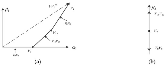
Figure 7.
The synthesis diagram of virtual vector : (a) α1-β1 subspace; (b) β3 pulse subspace.
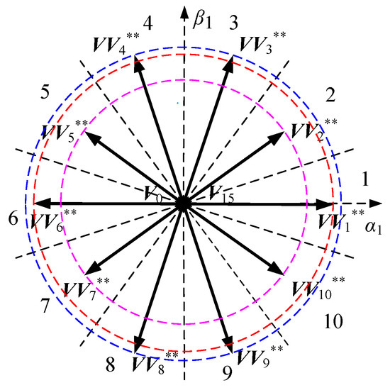
Figure 8.
The maximum amplitude virtual vectors in the α1-β1 subspace after the A phase OPF.
It can be seen that the directions of ten virtual vectors in Figure 8 (the faulty operation) are consistent with those in Figure 4 (the healthy operation), and the difference between the virtual vectors in the healthy and faulty operation is that the amplitudes of ten virtual vectors under the A phase OPF are reduced. Thus, there is no need to redivide the sectors and redesign the look-up table after the A phase OPF of five-phase PMSM drive system.
4.3. Implementation of the Proposed Fault-Tolerant Direct Torque Control Strategy
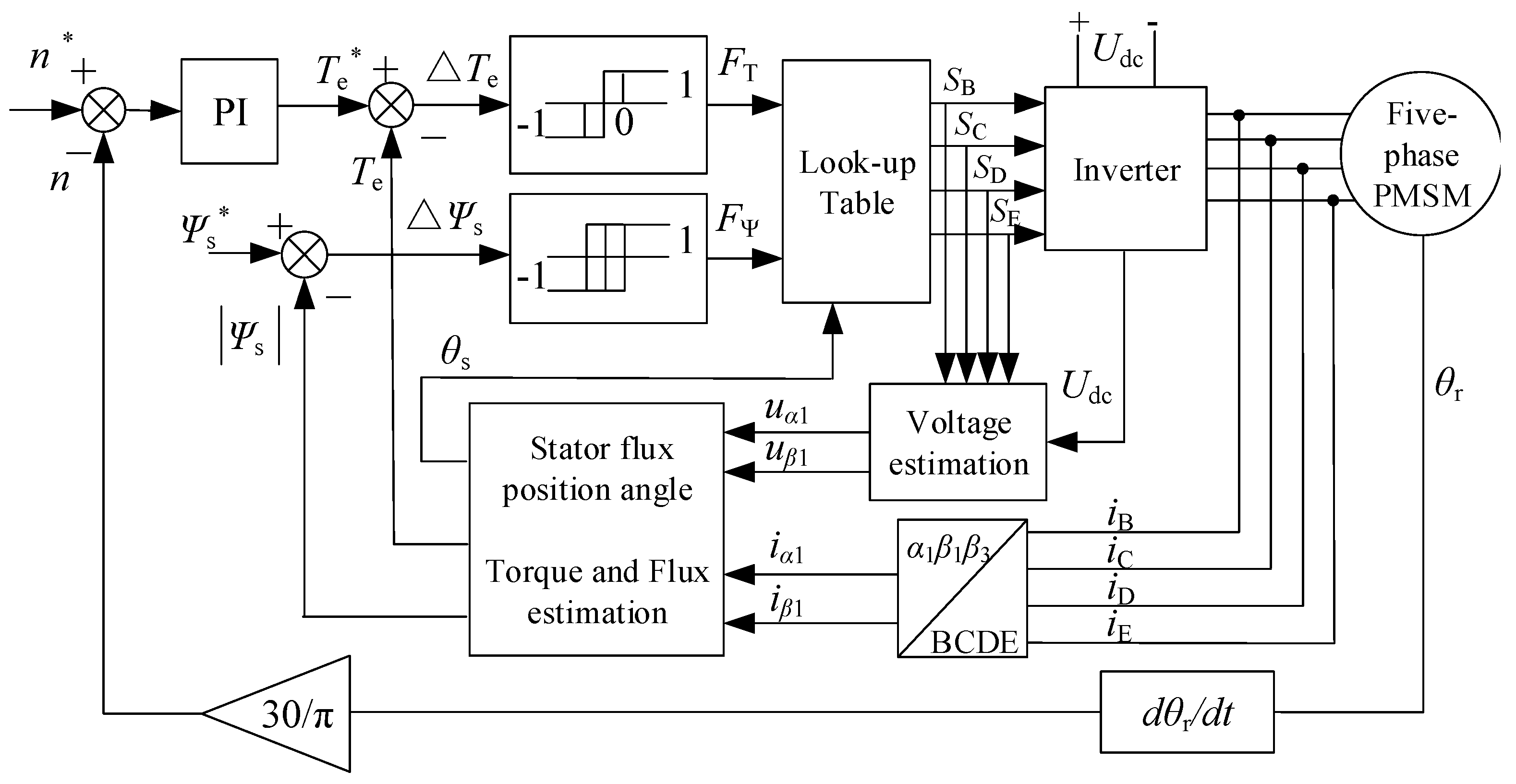
The block diagram of the fault-tolerant DTC for the five-phase PMSM based on virtual vectors is shown in Figure 9. The look-up table is consistent with the switch Table 2 during normal DTC control, but the virtual vectors are selected in Table 3 (the same amplitude) or Table 4 (the maximum amplitude). The same amplitude virtual vectors, which have equal but relatively small amplitudes, are suitable for the conditions of low speed and light load (THD and torque ripple are small). The maximum amplitude virtual vectors with unequal amplitudes can improve the utilization rate of the DC bus voltage and obtain large speed and torque output, which are suitable for the conditions of high speed and heavy load.

Figure 9.
Block diagram of fault-tolerant DTC algorithm based on virtual vector.
By using the back-EMF integration algorithm, the voltage model for the five-phase PMSM flux estimation can be expressed:
The torque estimation can be expressed as follows:
The flux space position angle θs of the stator flux is given below;
where ψα1, ψβ1 are the components of the flux linkage in the α1-β1 subspace. iα1, iβ1 are the components of the stator current in the α1-β1 subspace. Uα1, Uβ1 are the components of the stator voltage in the α1-β1 subspace. ψα1-0,ψβ1-0 are the initial flux linkages of α1 and β1 axes, respectively. |ψs| is the estimated amplitude of the flux linkage. Rs is the stator resistance. Te is the estimated torque value. np is the number of pole pairs.
5. Experimental Results
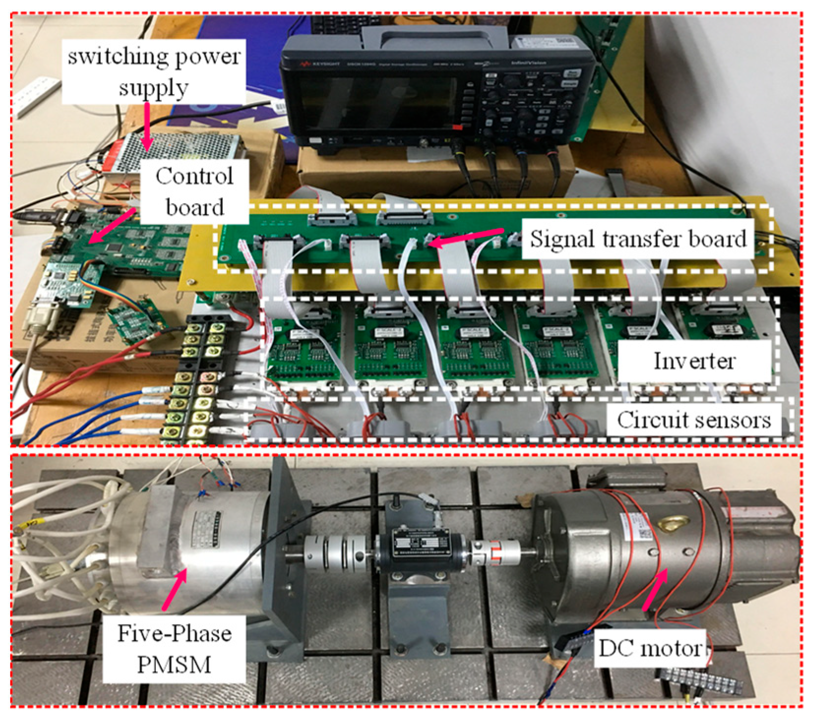
In order to verify the feasibility of the control strategy proposed in this paper, a five-phase PMSM experimental platform was developed, as shown in Figure 10. A DC motor was used as load, and XE164 of Infineon was used as the core controller. The five-phase voltage source inverter was composed of five Infineon IGBT half-bridge power modules FF300R12E4 in parallel. The parameters of the five-phase PMSM are listed as follows: Rs = 0.5 Ω, np= 4, Ld = Lq = 8.4 mH, and ψf = 0.32 Wb. The PWM control frequency was 10 kHz. The dead time was 2 μs. The motor speed was 200 rpm. The load torque was 7 N·m, and the DC bus voltage was 200V in the experiments. Due to the experimental conditions of low speed and light load, the subsequent experiments all adopt the method of the same amplitude virtual vectors (under the A phase OPF).

Figure 10.
Five-phase PMSM experimental platform.
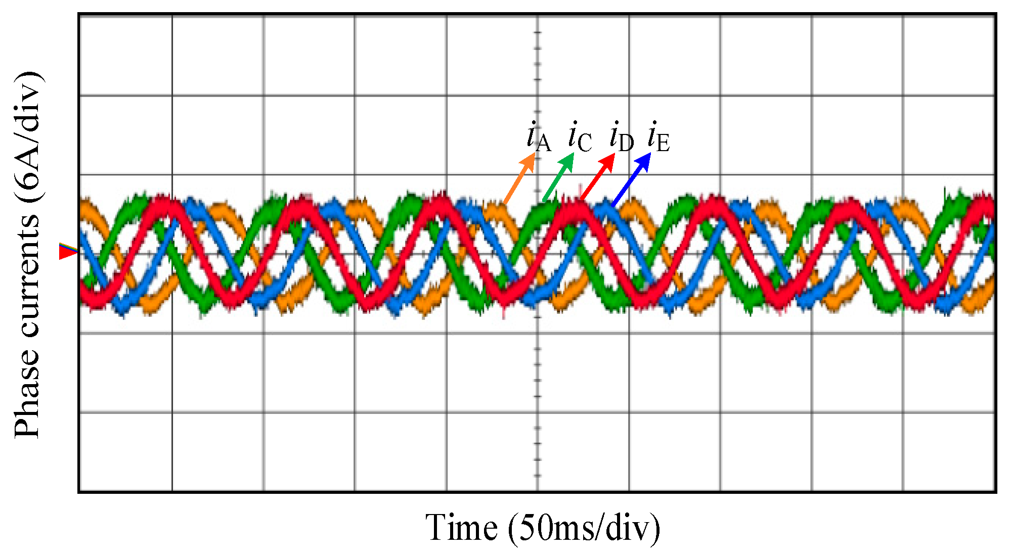
Figure 11 shows phase currents waveforms of the five-phase PMSM during the healthy operation. Under the healthy operation, the THD of the phase C current of the five-phase PMSM is 4.5%.
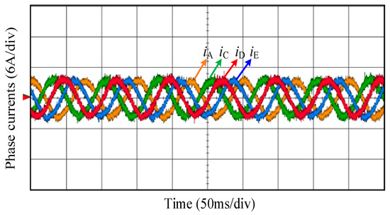
Figure 11.
Experimental waveform of phase currents under the healthy operation.
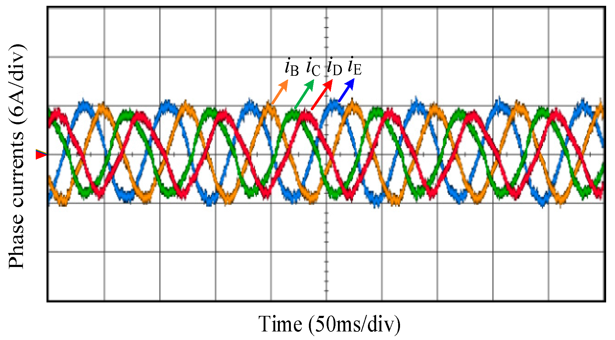
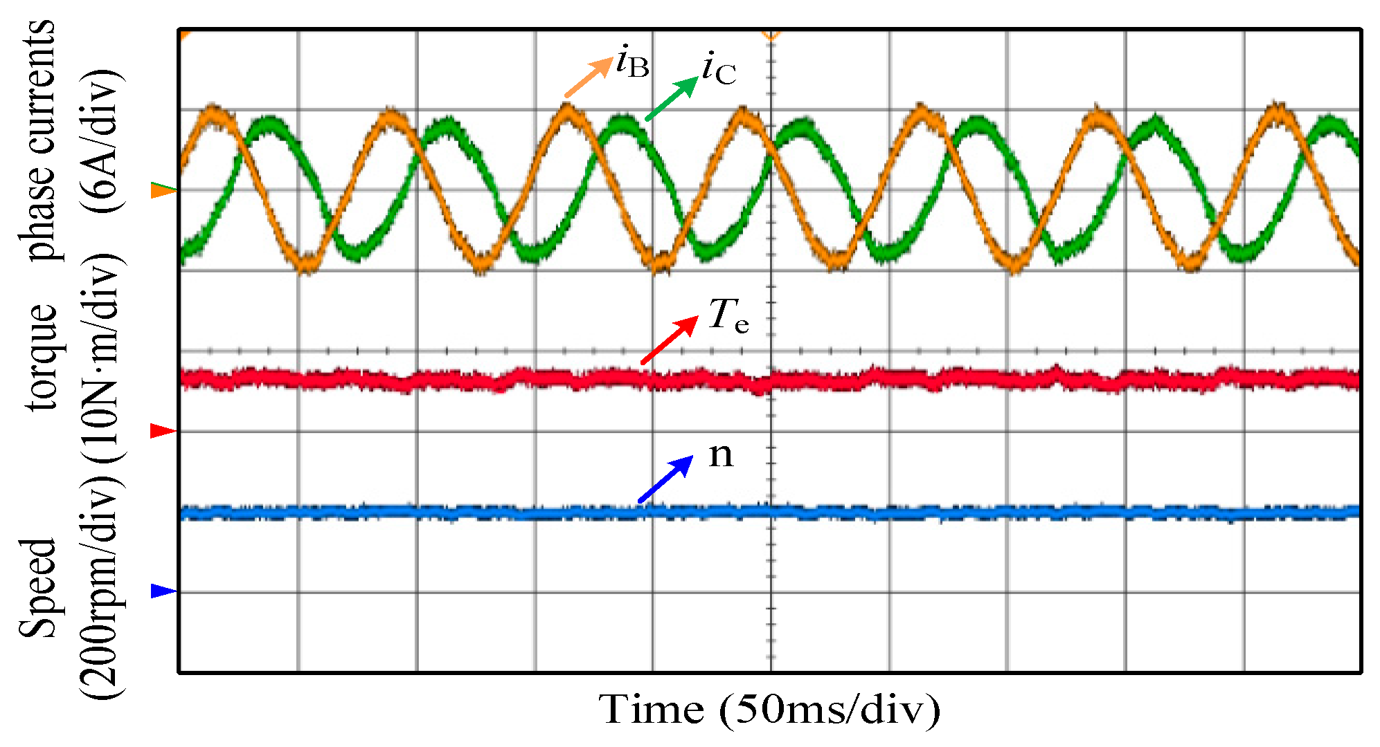
Figure 12 shows phase currents waveforms of the five-phase PMSM after the A phase OPF. It can be seen from Figure 12 that the remaining four phase currents after the A phase OPF have good sine quality. Because the principle of the minimum copper losses is adopted in this paper, the current amplitudes of phase B and E are higher than those of phase C and D. Under the fault-tolerant DTC strategy, the THD of the phase C current is 5.7%. Figure 13 shows waveforms of phase currents, torque, and speed in the steady state under the A phase OPF. It can be seen from Figure 13 that the torque ripple is small, and the speed is relatively smooth.
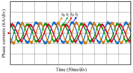
Figure 12.
Experimental waveform of phase currents under the A phase OPF.
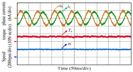
Figure 13.
Experimental waveforms of phase currents, torque, and speed under the A phase OPF.
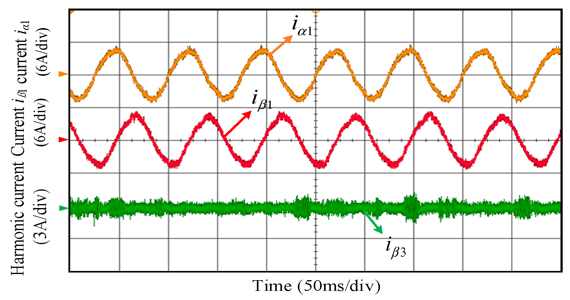
Figure 14 shows the current waveforms of the α1-β1 subspace and β3 pulse subspace under the A phase OPF. It can be seen from Figure 14 that the currents iα1 and iβ1 in the α1-β1 subspace after the A phase OPF have good sine quality, and the harmonic current iβ3 in the β3 pulse subspace is small. Thus, the steady-state performance under the A phase OPF is good.

Figure 14.
The currents waveforms of α1-β1 subspace and β3 pulse subspace under the A phase OPF.
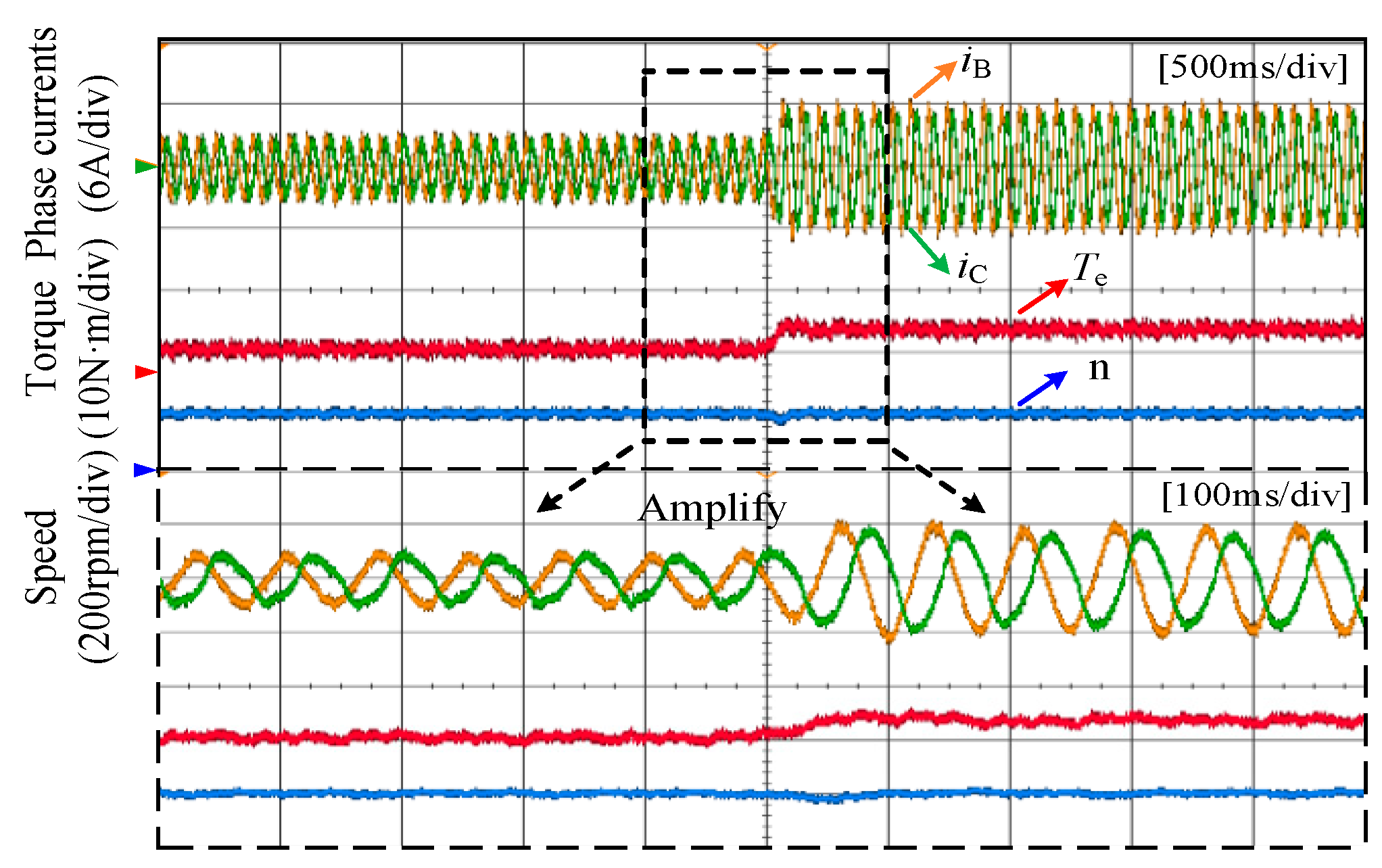
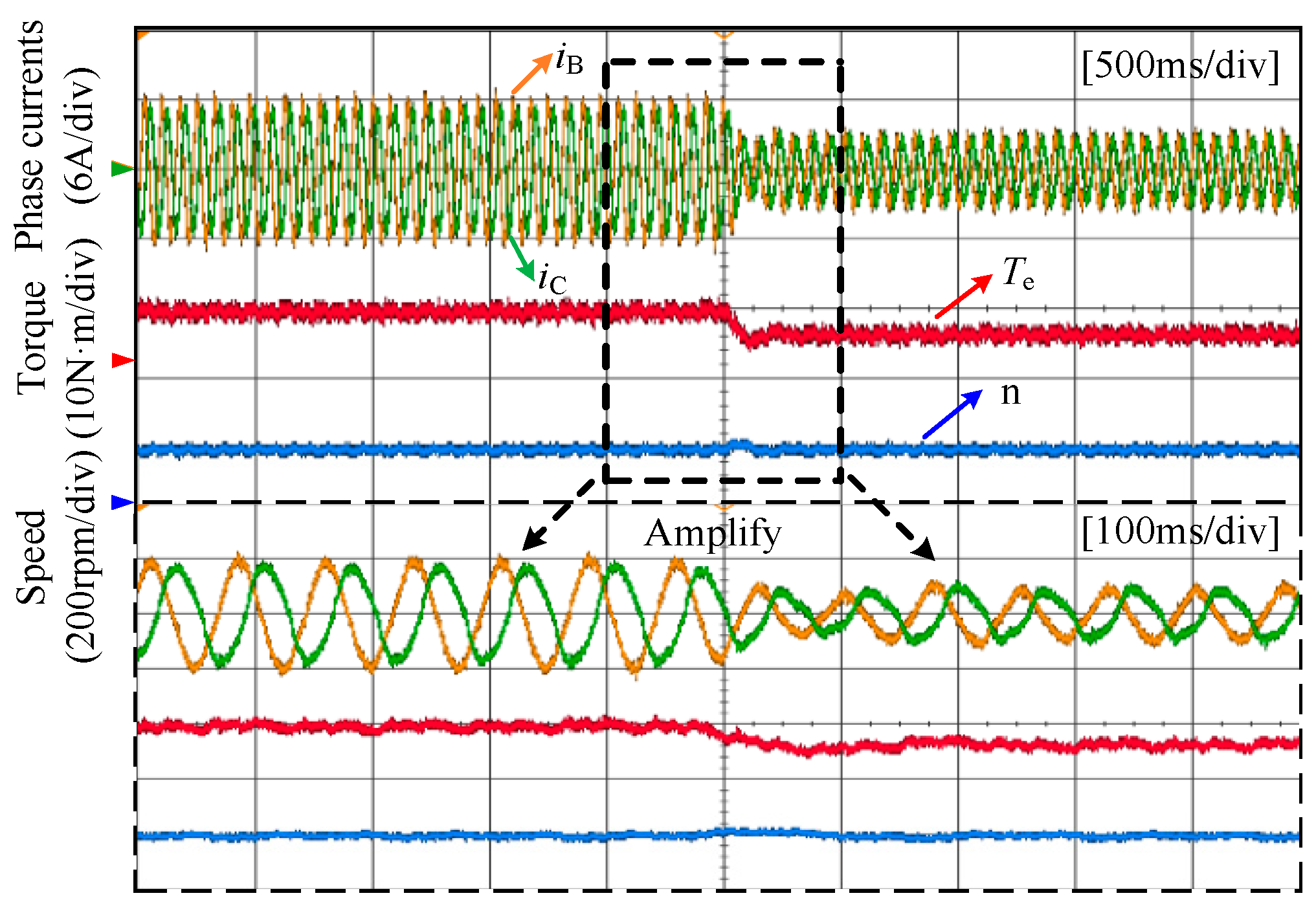
Figure 15 shows the waveforms of phase currents, torque, and speed when the load torque is suddenly increased from 4 N·m to 7 N·m. Figure 16 shows the waveforms of phase currents, torque, and speed when the load torque is suddenly reduced from 7 N·m to 4 N·m. The corresponding local amplification waveforms are given in Figure 15 and Figure 16. It can be seen that the phase currents and torque can be quickly tracked. With the sudden increase of the torque, the amplitudes of the phase currents become larger, and the torque can be quickly stabilized at 7 N·m. With the sudden reduction of torque, the amplitudes of the phase currents become smaller, and the torque can be quickly stabilized at 4 N·m. When the load torque is suddenly increased or reduced, there is a slight sudden change in speed, and the speed can restore to the reference value quickly.
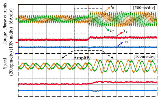
Figure 15.
The waveforms of phase currents, torque, and speed when load torque is suddenly increased.
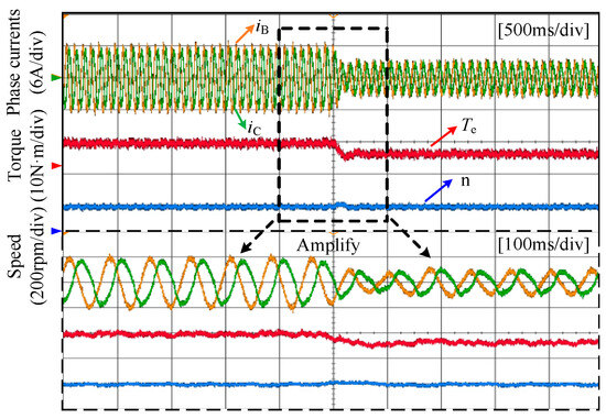
Figure 16.
The waveforms of phase currents, torque, and speed when load torque is suddenly reduced.
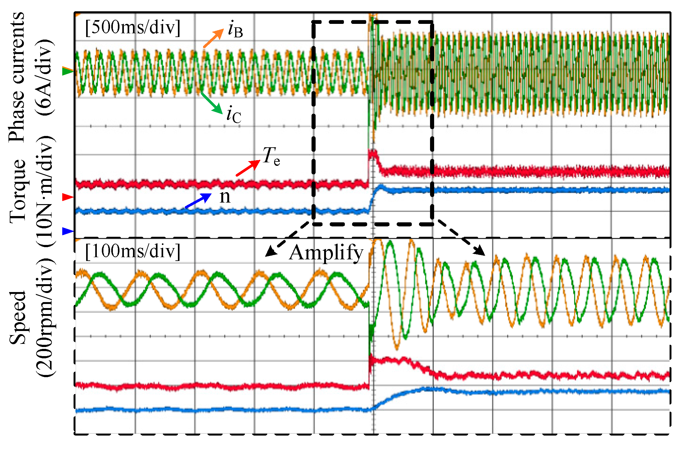
Figure 17 shows the waveforms of phase currents, torque, and speed when the speed is suddenly increased from 150 rpm to 300 rpm. The local amplification waveforms are given in Figure 17. It can be seen that the speed can be quickly tracked. With the sudden increase of speed, the speed can be quickly stabilized at 300 rpm. Therefore, the proposed control strategy has good dynamic response performance.
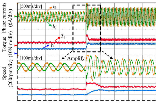
Figure 17.
The waveforms of phase currents, torque, and speed when speed is suddenly increased.
Figure 18 shows the experimental waveforms of the motor starting process. As can be seen in Figure 18, at the beginning of the starting process, the overshoot of the speed is small, and the speed and torque can quickly reach the reference value. Moreover, the currents of phase B and C can also reach stability quickly.
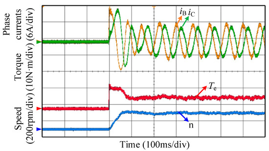
Figure 18.
The waveforms of the motor starting process under the A phase OPF.
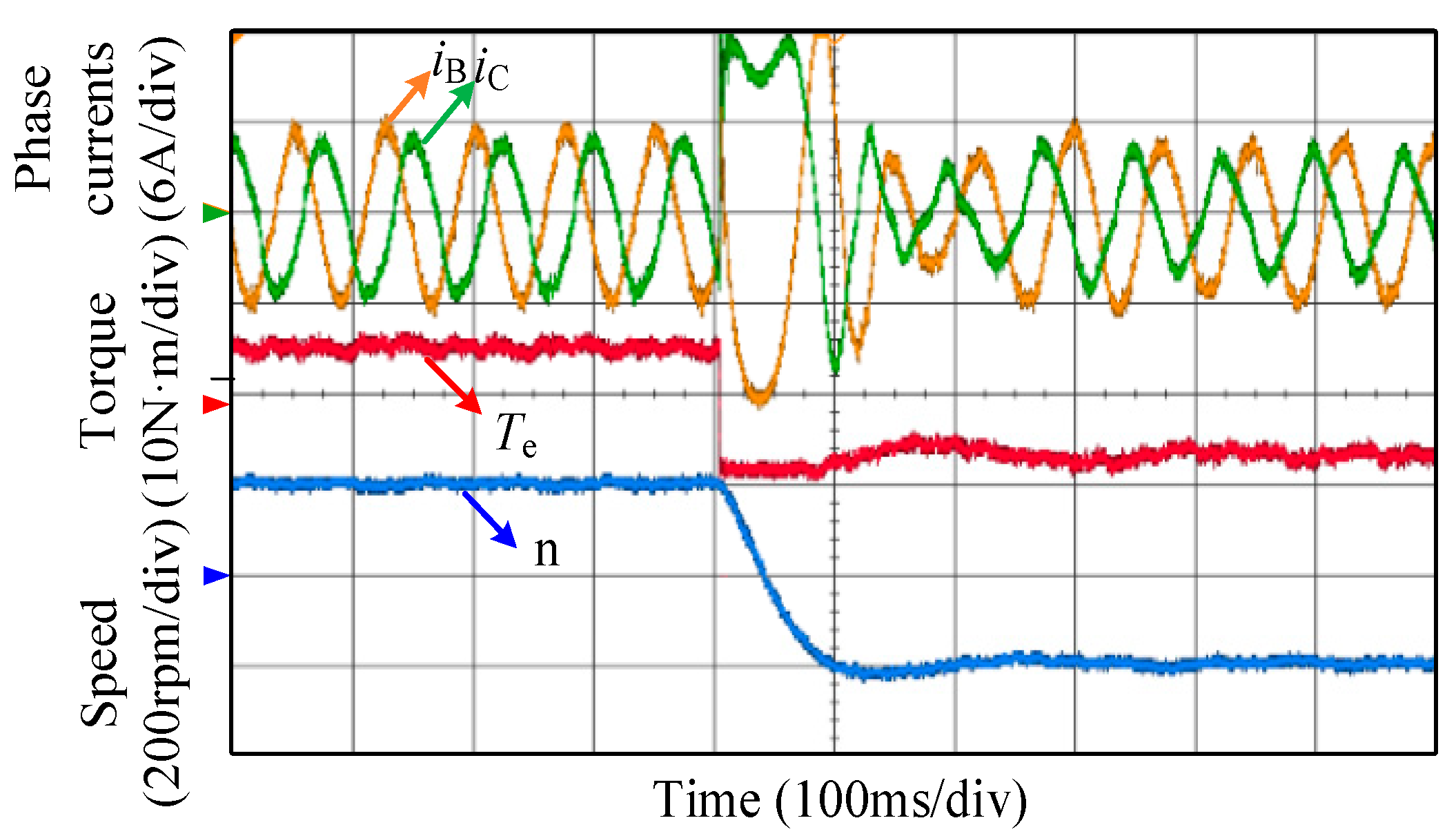
Figure 19 shows the experimental waveforms when the motor reverses from 200 rpm to −200 rpm. As can be seen in Figure 19, when the motor reverses, with the rapid adjustment, the torque and speed can reach stability quickly, proving that the proposed control strategy has good static and dynamic performances.

Figure 19.
The waveforms when the motor is switched from forward to reverse.
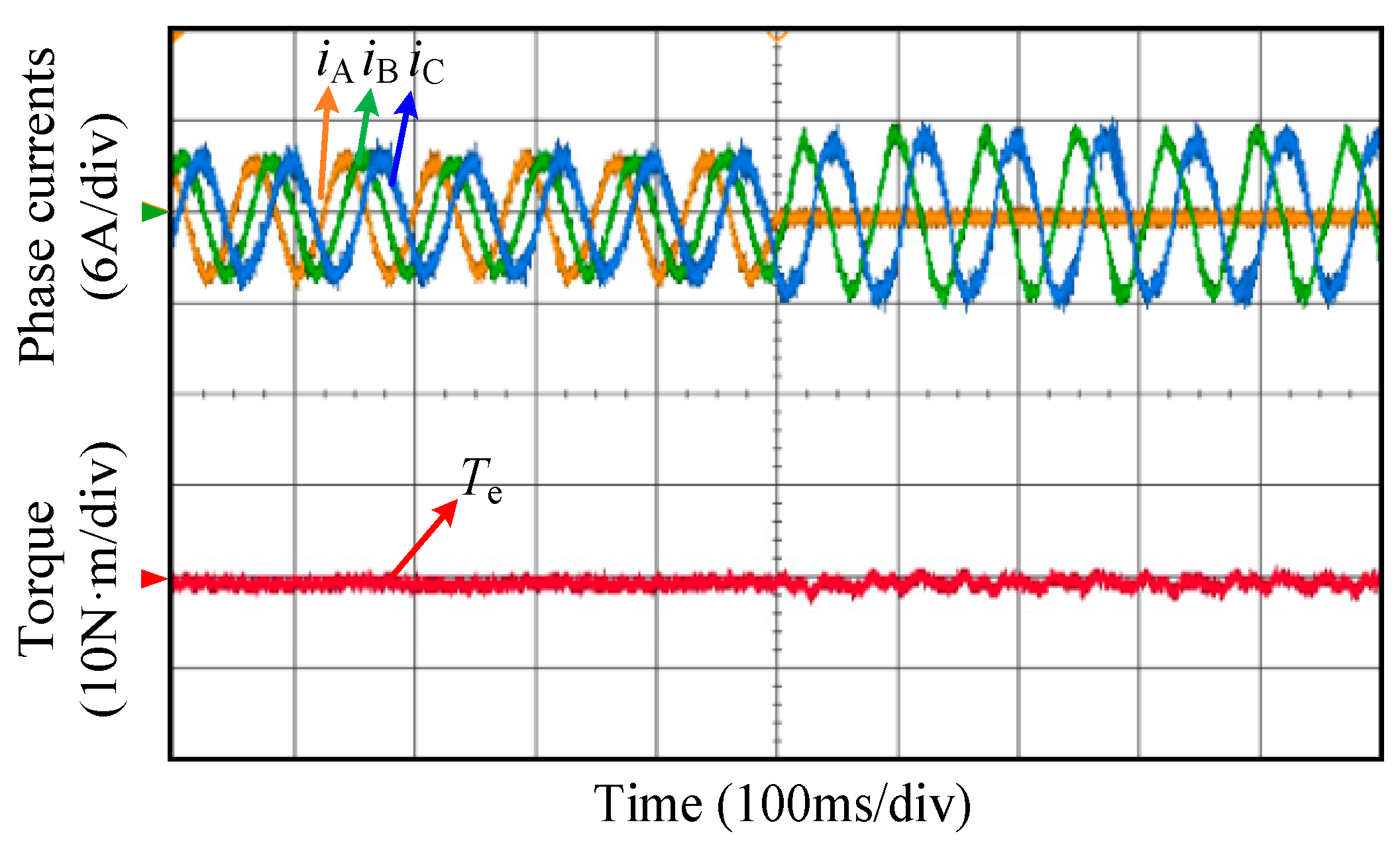
Figure 20 shows the switching waveforms of the five-phase PMSM from the healthy operation to the fault-tolerant DTC operation. It can be seen that the fault-tolerant DTC strategy proposed in this paper can achieve the smooth switching of the five-phase PMSM from the healthy operation to the fault-tolerant DTC operation.
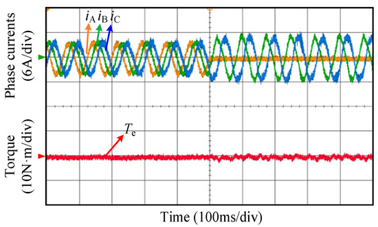
Figure 20.
Switching waveforms from the healthy operation to the fault-tolerant DTC operation.
6. Conclusions
This paper proposes an indirect correction method of virtual vectors for the five-phase PMSM drive system under single OPF. By the proposed indirect correction method, two kinds of virtual vectors can be obtained: the same amplitude and the maximum amplitude virtual vectors, where the maximum amplitude virtual vectors eliminate the zero vectors, and the maximum utilization rate of the DC bus voltage is realized. The difference between the virtual vectors in the healthy and faulty operation is that the amplitudes of ten virtual vectors under single OPF are reduced, and a fault-tolerant DTC strategy based on virtual vectors is proposed. This strategy can ensure that the sector distribution and the selection rules of look-up tables are consistent with those in the healthy operation, which simplifies the control process. In addition, the proposed fault-tolerant DTC strategy has good dynamic and static response performances. Without loss of generality, the virtual vectors’ indirect correction method proposed in this paper can also be extended to other multiphase motors and different types of OPFs. The virtual vectors can also be applied to the SVPWM and predictive current control of the multiphase motor under the OPF.
Author Contributions
C.Z. and R.Z. wrote the original manuscript, designed the experiment, and carried out the test; G.S. offered guidance and project supervision; D.Z. and X.Z. provided the necessary materials and equipment support; review and editing of the paper were mainly carried out by G.J. All the authors discussed the results and commented on the manuscript. All authors have read and agreed to the published version of the manuscript.
Funding
This work was supported in part by the Research Fund for the National Nature Science Foundation of China under Grant 51707157, in part by the Natural Science Basic Research Plan in Shaanxi Province under Grant 2023-JC-YB-377 and in part by the Shenzhen Polytechnic University Research Launch Project (6023312039K).
Data Availability Statement
The original contributions presented in the study are included in the article, further inquiries can be directed to the corresponding author.
Conflicts of Interest
Author Xiaopeng Zhao was employed by the company AVIC Xi’an Flight Automatic Control Research Institute. The remaining authors declare that the research was conducted in the absence of any commercial or financial relationships that could be construed as a potential conflict of interest.
References
- Levi, E. Advances in converter control and innovative exploitation of additional degrees of freedom for multiphase machines. IEEE Trans. Ind. Electron. 2016, 63, 433–448. [Google Scholar] [CrossRef]
- Barrero, F.; Duran, M.J. Recent Advances in the Design, Modeling, and Control of Multiphase Machines—Part 1. IEEE Trans. Ind. Electron. 2016, 63, 449–458. [Google Scholar] [CrossRef]
- Duran, M.; Barrero, F. Recent advances in the design, modeling and control of multiphase machines—Part 2. IEEE Trans. Ind. Electron. 2016, 63, 459–468. [Google Scholar] [CrossRef]
- Frikha, M.A.; Croonen, J.; Deepak, K.; Benômar, Y.; El Baghdadi, M.; Hegazy, O. Multiphase Motors and Drive Systems for Electric Vehicle Powertrains: State of the Art Analysis and Future Trends. Energies 2023, 16, 768. [Google Scholar] [CrossRef]
- Bensalem, Y.; Abbassi, A.; Abbassi, R.; Jerbi, H.; Alturki, M.; Albaker, A.; Kouzou, A.; Abdelkrim, M. Speed tracking control design of a five-phase PMSM-based electric vehicle: A backstepping active fault-tolerant approach. Electr. Eng. 2022, 104, 2155–2171. [Google Scholar] [CrossRef]
- Salehifar, M.; Arashloo, R.S.; Moreno-Eguilaz, J.M.; Sala, V.; Romeral, L. Observer-based open transistor fault diagnosis and fault tolerant control of five-phase permanent magnet motor drive for application in electric vehicles. IET Power Electron. 2015, 8, 76–87. [Google Scholar] [CrossRef]
- Trabelsi, M.; Nguyen, N.K.; Semail, E. Real-time switches fault diagnosis based on typical operating characteristics of five-phase permanent magnetic synchronous machines. IEEE Trans. Ind. Electron. 2016, 63, 4683–4694. [Google Scholar] [CrossRef]
- Liu, G.; Qu, L.; Zhao, W.; Chen, Q.; Xie, Y. Comparison of Two SVPWM Control Strategies of Five-Phase Fault-Tolerant Permanent-Magnet Motor. IEEE Trans. Power Electron. 2016, 31, 6621–6630. [Google Scholar] [CrossRef]
- Sun, G.; Yang, G.; Wang, Y.; Su, J. Unified Fault-tolerant Control Strategy with Torque Ripple Compensation for Five-phase Permanent Magnet Synchronous Motor Based on Normal Decoupling. Energies 2019, 12, 1127. [Google Scholar] [CrossRef]
- Prieto, I.G.; Duran, M.J.; Garcia-Entrambasaguas, P.; Bermudez, M. Field-Oriented Control of Multiphase Drives with Passive Fault Tolerance. IEEE Trans. Ind. Electron. 2020, 67, 7228–7238. [Google Scholar] [CrossRef]
- Tian, B.; Lu, R.; Hu, J. Single Line/Phase Open Fault-Tolerant Decoupling Control of a Five-Phase Permanent Magnet Synchronous Motor under Different Stator Connections. Energies 2022, 15, 3366. [Google Scholar] [CrossRef]
- Liu, G.; Song, C.; Chen, Q. FCS-MPC-Based Fault-Tolerant Control of Five-Phase IPMSM for MTPA Operation. IEEE Trans. Power Electron. 2020, 35, 2882–2894. [Google Scholar] [CrossRef]
- Gonzalez-Prieto, I.; Duran, M.J.; Aciego, J.J.; Martin, C.; Barrero, F. Model predictive control of six-phase induction motor drives using virtual voltage vectors. IEEE Trans. Ind. Electron. 2018, 65, 27–37. [Google Scholar] [CrossRef]
- Lim, C.S.; Levi, E.; Jones, M.; Rahim, N.A.; Hew, W.P. FCS-MPC based current control of a five-phase induction motor and its comparison with PI-PWM control. IEEE Trans. Ind. Electron. 2014, 61, 149–163. [Google Scholar] [CrossRef]
- Luo, Y.; Liu, C. A simplified model predictive control for a dual three-phase PMSM with reduced harmonic currents. IEEE Trans. Ind. Electron. 2018, 65, 9079–9089. [Google Scholar] [CrossRef]
- Zhou, Y.; Lin, X.; Cheng, M. A fault-tolerant direct torque control for six-phase permanent magnet synchronous motor with arbitrary two opened phases based on modified variables. IEEE Trans. Energy Convers. 2016, 31, 549–556. [Google Scholar] [CrossRef]
- Pandit, J.K.; Aware, M.V.; Nemade, R.V.; Levi, E. Direct torque control scheme for a six-phase induction motor with reduced torque ripple. IEEE Trans. Power Electron. 2017, 32, 7118–7129. [Google Scholar] [CrossRef]
- Zheng, L.; Fletcher, J.E.; Williams, B.W.; He, X. A novel direct torque control scheme for a sensorless five-phase induction motor drive. IEEE Trans. Ind. Electron. 2011, 58, 503–513. [Google Scholar] [CrossRef]
- Ren, Y.; Zhu, Z.Q. Reduction of Both Harmonic Current and Torque Ripple for Dual Three-Phase Permanent-Magnet Synchronous Machine Using Modified Switching-Table-Based Direct Torque Control. IEEE Trans. Ind. Electron. 2015, 62, 6671–6683. [Google Scholar] [CrossRef]
- Bermudez, M.; Gonzalez-Prieto, I.; Barrero, F.; Guzman, H.; Duran, M.J.; Kestelyn, X. Open-phase fault-tolerant direct torque control technique for five-phase induction motor drives. IEEE Trans. Ind. Electron. 2017, 64, 902–911. [Google Scholar] [CrossRef]
- Cheng, Y.; Du, Q.; Zhang, M.; Song, C.; Zhang, M. A Fault Tolerant Control Strategy and Simulation Analysis of Five-Phase Permanent Magnet Motors with Third-Harmonic Suppression. J. Xi’an Jiao Tong Univ. 2020, 54, 95–102+136. [Google Scholar]
- Payami, S.; Behera, R.K. An Improved DTC Technique for Low-Speed Operation of a Five-Phase Induction Motor. IEEE Trans. Ind. Electron. 2017, 64, 3513–3523. [Google Scholar] [CrossRef]
- Bermudez, M.; Gonzalez-Prieto, I.; Barrero, F.; Guzman, H.; Kestelyn, X.; Duran, M.J. An Experimental Assessment of Open-Phase Fault-Tolerant Virtual-Vector-Based Direct Torque Control in Five-Phase Induction Motor Drives. IEEE Trans. Power Electron. 2018, 33, 2774–2784. [Google Scholar] [CrossRef]
- Chikondra, B.; Muduli, U.R.; Behera, R.K. An Improved Open-Phase Fault-Tolerant DTC Technique for Five-Phase Induction Motor Drive Based on Virtual Vectors Assessment. IEEE Trans. Ind. Electron. 2021, 68, 4598–4609. [Google Scholar] [CrossRef]
- Chen, Q.; Liu, G.; Zhao, W.; Qu, L.; Xu, G. Asymmetrical SVPWM Fault-Tolerant Control of Five-Phase PM Brushless Motors. IEEE Trans. Energy Convers. 2017, 32, 12–22. [Google Scholar] [CrossRef]
- Tao, T.; Zhao, W.; He, Y.; Cheng, Y.; Saeed, S.; Zhu, J. Enhanced Fault-Tolerant Model Predictive Current Control for a Five-Phase PM Motor with Continued Modulation. IEEE Trans. Power Electron. 2021, 36, 3236–3246. [Google Scholar] [CrossRef]
- Xiong, C.; Xu, H.; Guan, T.; Zhou, P. A Constant Switching Frequency Multiple-Vector-Based Model Predictive Current Control of Five-Phase PMSM with Non-sinusoidal Back EMF. IEEE Trans. Ind. Electron. 2020, 67, 1695–1707. [Google Scholar] [CrossRef]

Disclaimer/Publisher’s Note: The statements, opinions and data contained in all publications are solely those of the individual author(s) and contributor(s) and not of MDPI and/or the editor(s). MDPI and/or the editor(s) disclaim responsibility for any injury to people or property resulting from any ideas, methods, instructions or products referred to in the content. |
© 2024 by the authors. Licensee MDPI, Basel, Switzerland. This article is an open access article distributed under the terms and conditions of the Creative Commons Attribution (CC BY) license (https://creativecommons.org/licenses/by/4.0/).