Review

Unveiling the Potential of Cryogenic Post-Combustion Carbon Capture: From Fundamentals to Innovative Processes

1
Department of Chemical Engineering, School of Engineering, The University of Manchester, Oxford Road, Manchester M13 9PL, UK
2
Research Unit of Process Engineering, Department of Science & Technology for Sustainable Development & One Health, University Campus Bio-Medico di Roma, Via Alvaro del Portillo, 21, 00128 Rome, Italy
*
Author to whom correspondence should be addressed.
Energies 2024, 17(11), 2673; https://doi.org/10.3390/en17112673
Submission received: 6 May 2024 / Revised: 27 May 2024 / Accepted: 28 May 2024 / Published: 31 May 2024
(This article belongs to the Section B: Energy and Environment)

Abstract

:
Climate change necessitates urgent actions to mitigate carbon dioxide (CO2) emissions from fossil fuel-based energy generation. Among various strategies, the deployment of carbon capture and storage (CCS) solutions is critical for reducing emissions from point sources such as power plants and heavy industries. In this context, cryogenic carbon capture (CCC) via desublimation has emerged as a promising technology. While CCC offers high separation efficiency, minimal downstream compression work, and integration potential with existing industrial processes, challenges such as low operating temperatures and equipment costs persist. Ongoing research aims to address these hurdles in order to optimize the desublimation processes for widespread implementation. This review consolidates diverse works from the literature, providing insights into the strengths and limitations of CCC technology, including the latest pilot plant scale demonstrations. The transformative potential of CCC is first assessed on a theoretical basis, such as thermodynamic aspects and mass transfer phenomena. Then, recent advancements in the proposed process configurations are critically assessed and compared through key performance indicators. Furthermore, future research directions for this technology are clearly highlighted.

1. Introduction

It is now widely recognized that climate change, standing as the most pressing challenge of our time, is driven primarily by anthropogenic activities. Among the unequivocal evidence, there are rising global temperatures, melting polar ice caps, ocean acidification phenomena, and increasingly erratic weather patterns [1]. In the pursuit of mitigating these impacts, the scientific community has tirelessly explored various strategies to reduce carbon dioxide (CO2) emissions, such as the following [1,2]:
  • Improvement of fossil fuel-based energy efficiency;
  • Enhancement of nuclear and renewable energy, as well as increasing use of biofuel-based energy;
  • Development of environmental engineering works, such as afforestation and reforestation.
On the other hand, during this period of ecological transition and contextual energy crisis, the belief of making our current economies independent from fossil fuels seems a utopia as the above mitigation strategies alone may fall short in achieving the necessary emission reductions [3,4]. Carbon capture and storage (CCS) would serve as a critical bridge, allowing industries with substantial point-source CO2 emissions, such as power generation and heavy manufacturing, to significantly curtail their carbon footprint.
After the capture process, CO2 is usually compressed and transported via pipelines to the storage or utilization facilities. In geographical regions without extensive pipeline infrastructure, CO2 could be transported in the liquid phase via ships. CO2 could then be injected and stored underground in geological formations such as depleted oil and gas wells, saline aquifers, and deep coal seams. CO2 could also react with certain minerals to form stable carbonates, providing a long-term storage solution. Moreover, CO2 utilization (CCU) involves converting the captured CO2 into valuable products, such as bulk chemicals, plastics, and synthetic fuels. This strategy, although energy and/or hydrogen-intensive, offers advantages in offsetting the cost of carbon capture by creating revenue streams [2,3,4,5].
The rising emphasis on achieving a net-zero society by the mid-century, as articulated in international agreements and embraced by nations and corporations alike, has propelled CCS into the forefront of climate change solutions. Policies and financial incentives aimed at fostering CCS deployment further underscore its integral role in achieving the decarbonization goals [3,4,5]. The key role of CCUS in reducing CO2 emissions can be justified by a number of reasons:
  • For decades to come, electricity generation will still rely on fossil fuels (due to the estimated lifetime of recently built or planned coal- and NG-based power plants), with estimated CO2 emissions of 25 Gt between 2020 and 2070 [5,6,7];
  • CCUS can be easily integrated into existing energy and utility systems without invasive or complex retrofits;
  • CCUS is currently the only viable option for decarbonizing emission-intensive industries (iron and steel, cement, chemicals, and petrochemicals) where the majority of CO2 emissions arise from the combustion of fossil fuels to generate high-temperature heat duties [6,7];
  • CCUS can be implemented for the production of low-carbon hydrogen (blue hydrogen): currently, around 76% of hydrogen (corresponding to 75 Mt y−1) is produced worldwide from natural gas, generating overall CO2 emissions exceeding 800 Mt y−1 [8]; green hydrogen produced by electrolysis is still expensive having a cost of USD 2.3–6.9 tH2−1 versus USD 1.4–2.4 tH2−1 from steam methane reforming (SMR) coupled with CCS [8,9];
  • CCUS has been regarded as a pivotal technology for allowing carbon-negative emissions if applied to plants processing biofuels and wastes (BECCS) or directly to atmospheric air (DAC) [3,4,10].
So far, diverse CCS technologies have been proposed; however, the quest for an efficient, scalable, and low-cost solution remains ongoing. Although the deployment of CCS projects has seen notable progress, the amount of CO2 captured and sequestered is relatively modest overall. Up to now, only a few Mt of CO2 have been captured globally, with various projects demonstrating the feasibility of CCS in different industrial settings. However, meeting the scale required for a meaningful climate impact would require a remarkable upscaling of CCS units. The International Energy Agency (IEA) has anticipated a substantial increase in the capture and storage of CO2, reaching Gt-scale levels by mid-century [5,6]. According to the IEA report, the Sustainable Development Scenario will meet the energy-related goals by fully eliminating CO2 emissions by 2070 [5,6]. Butnar et al. [11] examined different scenarios for European decarbonization, demonstrating that Europe needs a large-scale CCS industry to achieve its future goals. In the 1.5 °C scenario, the average CO2 captured by CCS would be in the range of 230–430 MtCO2 y−1 by 2030 and 930–1200 MtCO2 y−1 by 2050. Koelbl et al. [12] compared 18 integrated assessment models, showing that, although carbon capture rates will fluctuate in a wide range in the period 2020–2100, no model predicts less than 600 GtCO2 of cumulated captured emissions.
The selection of a specific capture technology depends on several factors, such as the CO2 concentration in the gas stream, the target CO2 purity and CO2 recovery, the allowed energy requirements, and additional constraints based on the specific industrial process. Three main strategies have been presented as follows. In post-combustion capture, CO2 is captured from the flue gases arising from the combustion of fossil fuels [13]. Pre-combustion capture involves capturing CO2 from H2-rich gas mixtures generated by the gasification of fossil fuels prior to the combustion [14]. Oxy-fuel combustion involves burning fossil fuels in an atmosphere enriched with oxygen rather than air [14]. This results in a flue gas stream predominantly composed of CO2 and water vapor, making it easier to separate CO2. A further strategy is offered by chemical looping combustion, which separates CO2 by using metal oxides as oxygen carriers circulating between two reactors [15].
Among the main carbon capture technologies, amine-based absorption has gained prominence for its efficacy in capturing CO2 from industrial flue gases. Examples of amine-based solvents are monoethanolamine (MEA), diethanolamine (DEA), and proprietary amines. After the absorption process, the CO2-rich solvent is regenerated by providing heat to release the captured CO2 [16]. Alternative solvents, such as ionic liquids, have also been proposed as they offer some advantages with respect to amines, including low volatility, low regeneration temperatures, and potential for tunability [17]. In pressure swing adsorption (PSA) processes, nanoporous adsorbents, such as zeolites and metal-organic frameworks, selectively adsorb CO2 at high pressure. The adsorbent is then regenerated at low pressures, sometimes under vacuum, to release the captured CO2 [18,19]. Temperature swing adsorption (TSA) processes rely on temperature variations to desorb CO2 from the adsorbent material. Furthermore, membrane technology based on polymeric, metallic or ceramic materials uses selectively permeable membranes to separate CO2 from other flue gases by exploiting differences in molecular size, shape, or affinity [20].
As the demand for more sustainable and energy-efficient solutions grows, attention has turned to cryogenic carbon capture as a promising technology in this field. Cryogenic separation involves cooling the flue gas stream to very low temperatures, causing CO2 to condense or desublimate while the other gases remain in the gaseous phase. Cryogenics refers most closely to processes that occur at temperatures below 120 K (−153 °C), such as the condensation of nitrogen and oxygen; however, the term is often used to indicate in a generic way low-temperature separations [21]. While the idea of cryogenic separation has been explored for decades, recent advancements and successful pilot projects have reignited interest in its potential as a game-changing carbon capture technology [21,22]. The earliest works on cryogenic flue gas treatment were developed by the Bechtel Power Corporation on cryogenic SO2 capture from a coal plant [22]. In the last few decades, many patents have been filed in relation to CH4 purification. Holmes and Ryan [23] proposed a conventional cryogenic distillation for the separation of CH4 from CO2 with extractive distillation [23] using an entrainment solvent (n-butane) to control the CO2 freezing. Amongst other technologies, the CryoCell® process was developed by Cool Energy and tested in collaboration with other industrial partners, including Shell Global Solutions, in order to cryogenically remove CO2 from natural gas [24].
In the field of post-combustion carbon capture, cryogenic separation is considered energy-intensive but highly effective. The numerous advances in the cryogenic sector have also pushed research to adopt CCS solutions to treat combustion flue gases. However, several works were related to vapor–liquid equilibrium and, therefore, were limited to gas purifications having a high concentration of CO2 in the feed stream [25,26]. For instance, Berstad et al. [27] analyzed low-temperature CO2 capture processes from IGCC plants by condensation and phase separation, identifying feasible design configurations and determining a specific energy requirement of around 300 kJ kgCO2−1 with a CO2 capture recovery of 85%.
More recently, various scientific works have identified the importance of vapor–solid equilibrium to achieve high CO2 purities and recoveries, even from flue gases at low pressures and low CO2 concentrations, and have thus laid the foundation for the thermodynamic understanding and engineering principles of cryogenic desublimation. For instance, some research groups have proposed cryogenic packed beds operating in parallel and undergoing different cycle steps [28,29]. Other researchers have developed prototypes and the first pilot plants based on CO2 desublimation, showcasing the feasibility of implementing cryogenic carbon capture [30]. Overall, according to the literature reviewed in the present work, cryogenic carbon capture (CCC) based on CO2 desublimation from post-combustion flue gases offers several advantages compared with other technologies as follows:
  • The technology features extremely high selectivity and thus minimizes the competitive capture of other components in the flue gases;
  • The separation process is driven by temperature differences and does not rely on solvents, adsorbents or membranes;
  • The CO2 product is generally extracted in the liquid phase so as to avoid the downstream compression work;
  • Scalability potential and a wide range of applications have been demonstrated. In addition, CCC can be integrated into existing industrial processes with minimal retrofit requirements;
  • CCC is characterized by low water consumption and offers a large heat integration potential. This, in turn, minimizes the disposal of waste and enhances safety and environmental aspects.
While these advantages make CCC an intriguing option, it is also important to acknowledge that several challenges exist, including the need for very low operating temperatures, the high cost of equipment materials, and the overall feasibility of large-scale implementation. Ongoing research and developments are essential to address these challenges and optimize CCC for widespread application. In the last few years, various review articles have been published discussing both modeling and experimental aspects of cryogenic desublimation methods for post-combustion carbon capture [21,26,31,32,33].
Shen et al. [26] focused on cryogenic capture systems from the perspective of constructing new cryogenic capture system structures, exploring the optimal system parameters, and analyzing the challenges faced. Font-Palma et al. [21] presented the first comprehensive review on the topic. Song et al. [31] systematically discussed several CCC technologies, including standalone process schemes and hybrid schemes coupled with cold sources such as LNG regasification [31]. Asgharian et al. [32] published a review paper on process modeling of CCC, focusing on thermodynamics and energy-related aspects. Aneesh and Sam [33] evaluated additional theoretical aspects of CCC technologies, such as mass transfer mechanisms.
All the above works often focused on a limited research area, either thermodynamic aspects or process configurations. Furthermore, these works often included process schemes that are based on vapor–liquid equilibrium and/or hybrid schemes to purify CH4 rather than capture CO2. This means that the presented results are heterogeneous and do not represent a systematic classification of the processes based on cryogenic desublimation. In addition, desublimation-based technology is experiencing a rising interest, with the first demonstration pilot plants being built and operating, which could confirm the theoretical and modeling aspects investigated in the previous papers.
Based on these considerations, a novel and comprehensive review work on this topic is necessary. This paper delves into the evolution of cryogenic carbon capture by desublimation, emphasizing both the strengths and limitations of the latest process schemes. It meticulously explores the engineering principles behind desublimation, ranging from thermodynamics to mass transfer phenomena. By critically evaluating the achievements of pilot plants and commercial solutions, we aim to elucidate the transformative potential of cryogenic carbon capture, shedding light on recent breakthroughs and real-world applications. This will be achieved by discussing the main process schemes and comparing the key performance indicators of the proposed technologies.

2. Fundamentals of Cryogenic Desublimation

To predict the phase equilibria involved in cryogenic desublimation processes, cubic equations of state (EoS), including Soave–Redlich–Kwong (SRK), Peng–Robinson (PR), and Patel–Teja (PT), can be used coupled with a relatively small amount of experimental data to determine their mixing rules parameters [34]. Several works have studied theoretically and experimentally CO2 desublimation in the oil and gas industry. De Guido et al. [35] demonstrated the reliability of their thermodynamic modeling in representing solid–liquid–vapor equilibrium (SLVE), with a focus on obtaining CO2 solubility predictions in hydrocarbon-rich mixtures (notably for natural gas purification). The same authors also described the solid–vapor equilibrium (SVE) for CO2-CH4 and CO2-CH4-N2 mixtures, applying both selected cubic EoS and the Gibbs energy minimization method [36]. A parallel field of studies was also related to the prediction of the Joule–Thomson effect, where Wang et al. [37] developed and validated an improved 25-parameter model. Below the most commonly used set of equations to describe the SVE of CO2 in a flue gas mixture and to predict CO2 dew and freezing points is reported. In particular, Equation (1) represents the isofugacity condition for the SVE, while the PR EoS shown in Equation (2) is used to calculate the fugacity coefficients of CO2 in both solid and vapor phases. The sublimation vapor pressure of CO2 can be determined using Equation (3), as tested by Jensen et al. [30].
ϕ C O 2 S · P C O 2 S · e v C O 2 S · P P C O 2 S R · T = y C O 2 · ϕ C O 2 V · P
P = R · T v b a T v · v + b + b · ( v b )
P C O 2 S = exp 57.52 + 3992.84 T 4.9003 · ln T + 2.415 · 10 15 · T 6 + 8125.6 T 2
In the above equations y C O 2 , ϕ C O 2 V , P , P C O 2 S , ϕ C O 2 S and v C O 2 S represent the mole fraction of CO2 in the vapor phase, the fugacity coefficient of CO2 in the vapor phase, the total pressure, the sublimation vapor pressure of CO2, the fugacity coefficient of CO2 at the saturated solid pressure and the molar volume of solid CO2, respectively. It should be noted that in Equation (1), the solid phase is represented by pure CO2. Several modifications of the above equations are reported in the literature, especially for the binary interaction parameters of the cubic EoS [30,38,39]. In the works of both Jensen et al. [30] and Pellegrini et al. [38], SVE calculations have been implemented by minimizing the Gibbs energy of the system. Most theoretical data have also been validated through dedicated experimental campaigns [30,38].
In this work, similar results based on SVE were achieved using Aspen Plus V10.0 software. To obtain these data, the RGibbs reactor was selected. The CO2 solid phase was formed as a result of a chemical equilibrium reaction from the gas phase. The results were obtained for binary systems of CO2 and N2 considering two CO2 concentrations in the feed: 5 mol% as representative of natural gas-fired power plant flue gases and 15 mol% as representative of coal-fired power plant flue gases.
Figure 1a shows the CO2 recovery in the solid phase against the flue gas temperature according to the SVE model at three different pressure levels and two inlet CO2 concentrations. Figure 1b shows the flue gas temperature required to obtain a certain CO2 recovery in the solid phase at a given pressure, starting with a flue gas having a CO2 composition of 15%. In Figure 1b, simulation results are compared against the calculations carried out by Pellegrini et al. [38] and Baxter et al. [40]. In the case of low CO2 concentrations (5%) in the feed, high CO2 recoveries are achievable only by operating at temperatures below 150 K or considering flue gases at higher pressures. However, these temperature levels could be raised to around 170 K if the flue gases contain 15% of CO2 at relatively low pressures.
Overall, it is possible to obtain a minimum work of separation in the order of 1 MJ kgCO2−1 at these temperatures and for inlet CO2 concentrations of around 15%. Yurata et al. [41] carried out process simulations involving CO2-H2 mixtures, demonstrating the thermodynamic superiority of desublimation processes against other unit operations. Energy consumption values of 1–2 MJ kgCO2−1 represent an enormous advantage compared with the state of the art of technology, especially considering that for many cryogenic solutions the compression/liquefaction work necessary for the CO2 transport is minimized.
According to chemical thermodynamics, the minimum work of separation required to separate CO2 from the other flue gases (inert) involves overcoming the thermodynamic barrier associated with the gas mixing. This corresponds to the opposite of the Gibbs energy of mixing between two products (p1, p2) and the feed (f) in a generic separator, as indicated by Equation (4) [13,42]. In addition, the subsequent compression and/or liquefaction of CO2 is a crucial aspect in evaluating the efficiency and feasibility of carbon capture processes [13,22]. A more accurate calculation can be attained by including the theoretical work of compression and/or liquefaction to deliver CO2 in a dense phase. For instance, purified CO2 must usually be compressed to very high pressures to overcome the pressure drops in the pipelines and injected in the form of supercritical fluid into reservoirs at depths of the km order of magnitude. The minimum work required to compress the purified CO2 is calculated using Equation (5) and corresponds to a reversible isothermal compression. Considering a hydrostatic pressure of roughly 1 MPa per 100 m of depth, the battery limits for CO2 delivery would be around 10–15 MPa. Alternatively, a liquefaction process can be considered by including the theoretical heat removal by liquefaction in a reversible refrigeration cycle, as reported in Equation (6).
In chemical thermodynamics, the minimum work of separation required to separate CO2 from the other flue gases (inert) involves overcoming the thermodynamic barrier associated with the gas mixing. This corresponds to the opposite of the Gibbs energy of mixing between two products (p1, p2) and the feed (f) in a generic separator, as indicated by Equation (4) [13,42]. In addition, the subsequent compression and/or liquefaction of CO2 is a crucial aspect in evaluating the efficiency and feasibility of carbon capture processes [13,22]. A more accurate calculation can be attained by including the theoretical work of compression and/or liquefaction to deliver CO2 in a dense phase. For instance, purified CO2 must usually be compressed to very high pressures to overcome the pressure drops in the pipelines and to be injected in the form of supercritical fluid into reservoirs at depths of the km order of magnitude. The minimum work required to compress the purified CO2 is calculated using Equation (5) and corresponds to a reversible isothermal compression. Considering a hydrostatic pressure of roughly 1 MPa per 100 m of depth, the battery limits for CO2 delivery would be around 10–15 MPa. Alternatively, a liquefaction process can be considered by including the theoretical heat removal by liquefaction in a reversible refrigeration cycle, as reported in Equation (6).
W s e p m i n = R T n c C O 2 ln y c C O 2 + n c i n e r t ln n c i n e r t                                                    + R T n b C O 2 ln y b C O 2 + n b i n e r t ln n b i n e r t                                                    R T n m C O 2 ln y m C O 2 + n m i n e r t ln n m i n e r t
W c o m p m i n = R · T · l n P o u t P i n
W c o n d m i n = Q c o n d · T T c o n d 1
η I I =   W s e p m i n + W c o m p m i n + W c o n d m i n W s e p + Q s e p · 1 T 0 T s e p + W c o m p + W c o n d
where the specific thermal duty for condensation Q c o n d coincides with the latent heat of vaporization. The minimum work of separation is reported in Figure 2 for an inlet CO2 concentration of 15% as a function of the CO2 recovery in the solid phase. The calculated value for separating 90% of CO2 into a pure CO2 stream and a second N2-enriched stream is 140 kJe kgCO2−1. By considering liquefaction occurring at 50 bar and a work of compression also at 50 bar, the resulting total minimum work of separation was around 400 kJe kgCO2−1. In fact, it has been reported that optimized compression and liquefaction with external refrigeration (e.g., ammonia refrigeration cycle) consume about 100 kWh tCO2−1 [43]. These values can be compared to the actual work of separation, which can be expressed through the II law efficiency shown in Equation (7). Quantifying the contributions from an energy point of view allows us to use a second law efficiency and, therefore, to compare a theoretical separation work to the thermal or mechanical energy used in a real system. In fact, the numerator of Equation (7) represents the useful product, while the denominator represents the equivalent work, including the transformation of thermal energy into mechanical energy (higher quality). More refined methods are presented in the cited literature [13,44,45]. The actual work of separation could then represent a better comparison with the real energy penalties obtained in the CCS projects deployed worldwide.
To account for the energy consumption in a cryogenic desublimator, we can refer to the schematic shown in Figure 3, adapted from Swanson et al. [22], who performed theoretical calculations for energy penalties associated with CCC. In the figure, the flue gas is pre-cooled by recovering the internal cold energy, including the cold CO2 product and the cold CO2-lean flue gas streams. The wavy lines represent the cut of a virtual surface at the control volume on which we realize the energy and exergy balance. The red arrows represent the thermal power exchanged, while the blue arrows represent the mechanical power. Recuperative heat exchangers are expected to pre-cool the incoming flue gas. Depending on the operating conditions, the recovery ratio and the selected temperature pinch within the recuperative heat exchanger, the process may require an external refrigeration cycle. As can be seen from the figure, there are two types of heat removal strategies: (i) cold energy recovery from internal process streams such as the clean gas or the recovered liquid CO2; (ii) refrigeration by expending mechanical/electrical energy, i.e., using a refrigeration cycle. According to Swanson et al. [22], and as reported in some real process schemes, two types of refrigeration cycles could be implemented: one with a higher coefficient of performance (COP) rejecting the heat to an internal stream (e.g., the solid CO2 is used as a low-temperature heat sink for a portion of the heat that must be rejected by the refrigeration system) and another one with a lower COP rejecting the heat at ambient temperature. Rejecting the heat to a cold stream is less costly than rejecting the heat at ambient temperature. However, the choice of the refrigeration cycle will depend on the equipment design and the dichotomy between capital costs and operational costs due to the low temperatures involved.
Downstream of the separation, the energy costs to compress CO2 to the required pipeline pressures are usually very limited since CO2 is already in the liquid phase. For instance, when pressurizing 1 kg of liquid CO2 at 220 K from atmospheric pressure to 120 bar, the resulting enthalpy change is only 4 kJ. This leads to an overall energy consumption of around 450 kJ kgCO2−1 with 90% CO2 recovery, which is comparable to the total minimum works of separation shown in Figure 2. Although the real desublimation processes described in the following sections disclosed slightly higher values of energy consumption, cryogenic processing can be considered very close to the thermodynamic optimum. For instance, in amine-based absorption systems, the energy required for solvent regeneration constitutes a significant portion of the overall work of separation and, if summed to the compression and transportation energy requirements, can total approximately 4–6 MJ kgCO2−1 [13,16]. This means that, compared with the benchmark processes, cryogenic processes can push the II law efficiency of carbon capture from around 20% to more than 50%.
Desublimation can occur from the gaseous bulk phase toward a cold surface or through direct contact with a cold liquid (cryogenic fluid). From the point of view of the design of unit operations, the flue gas can be treated as a stream of non-condensable gases saturated with CO2, and the formalism presented by classic chemical engineering textbooks can be used to obtain the basic design of the equipment for heat and mass transfer [42]. The heat and mass balances to determine the gas temperature TG and the gas composition yCO2 along the axial dimension z can be drawn according to the film theory for gas desublimation in a mixture of non-condensable gases in countercurrent contact with a cold liquid, as exhibited in Figure 4. The figure shows the schematics of the film (considering that the liquid cannot vaporize), the control volumes of the gas flowing from bottom to top, and the liquid flowing from top to bottom of a desublimating separator considering the 1-dimensional case of a direct-contact desublimating separator. The CO2 flux occurs through the interface, and the separated solid CO2 falls down into the descending liquid phase that is not volatile (not present in the gaseous phase).
Heat and mass balances can be generalized by applying them to a control volume between the flue gas mixture from which CO2 is separated and the cryogenic liquid. Considering a separator section of height dz, the following equations represent the heat fluxes exchanged for sensible heat (Equation (8)) and latent heat (Equation (9)) by the gas phase. Equation (10) describes the heat flux transferred to the cryogenic liquid. These equations are also valid for a heat exchanger with a wall between liquid and gas phases under the assumption of the wall having negligible thermal resistance. By neglecting the sensible heat of solid CO2 and assuming that the specific surface related to mass transfer coincides with the specific surface related to heat transfer, the balance of fluxes q s L = q s G + q λ G can be used to calculate the interface temperature.
q s G = h G · T G T i
q λ G = λ C O 2 · k Y · y C O 2 y C O 2 , i
q s L = h L T i T L
The mathematical modeling and the related algorithms to define the temperatureconcentration profile of a desublimator are similar to those determined for vapor mixtures containing both condensable and non-condensable gases. Simplified methodologies to calculate the direct contact heat and mass transfer apparatus can be found for systems characterized by a Lewis number approximately equal to 1 (air-water humidification and dehumidification systems) [42]. In this case (CO2-flue gases-cryogenic liquid), the heat and material balances should be numerically integrated to determine the temperature of the phase interface, as well as the temperatures of the liquid and gas phases and the CO2 concentration profile. In the field of desublimation, there are no complete theoretical works that combine thermodynamic aspects and heat and mass transfer phenomena. A few modeling works are available for desublimation equipment, although most of these works have not been fully validated against experimental data. Only Asgharian et al. [32] provided a detailed numerical framework for the modeling of the main components constituting a cryogenic carbon capture process, including CO2 separators, storage tanks, heat exchangers, and turbomachinery. Table 1 details the main modeling features of works from the literature related to CCC by desublimation.

3. Processes Based on Cryogenic Desublimation

Cryogenic carbon capture based on SVE takes advantage of the unique thermodynamic property that CO2 exists in a gaseous phase at atmospheric pressure and, therefore, desublimates to a solid phase in a temperature range of 130–180 K, depending on its concentration in the flue gases. This is because CO2 exhibits an exceptionally high triple point pressure of 518 kPa [54]. This separation method can obtain very high CO2 purities (99.9+%) and CO2 recoveries (90–99%) simultaneously, along with ease of CO2 transportation and storage. However, as already mentioned, there also exist important limitations associated with this technology, including the risk of blockages from condensed water, CO2 frosting in pipelines and storage tanks, and increased capture costs due to the cold energy sources [31,55].
Nevertheless, for post-combustion carbon capture applications, i.e., when the CO2 concentration in the flue gases ranges from 5 and 15 mol%, cryogenic desublimation has shown a substantially lower energy consumption compared with other technologies, even in the cryogenic sector, e.g., cryogenic distillation and condensation. Being based on liquid–vapor equilibrium, in fact, cryogenic distillation requires higher operational pressures and has been successfully proposed for treating gas mixtures with a high CO2 content (20–70 mol%), such as natural gas, shifted syngas, and biogas streams [23,26].
The block flow diagram of a generic cryogenic desublimation process is shown in Figure 5. The flue gases are first dried to remove the moisture content and then cooled down below the freezing temperature of CO2, where the gas desublimates at a temperature range defined by the CO2 concentration in the flue gases and the capture efficiency of the process. Solid CO2 is then separated and normally liquefied for ease of transportation and storage. Several process configurations feature additional steps of pre-treatment, compression, expansion, and heat integration between the main steps in Figure 5. In the next sub-sections, the latest developments and challenges of the post-combustion carbon capture processes based on cryogenic desublimation will be presented and discussed.

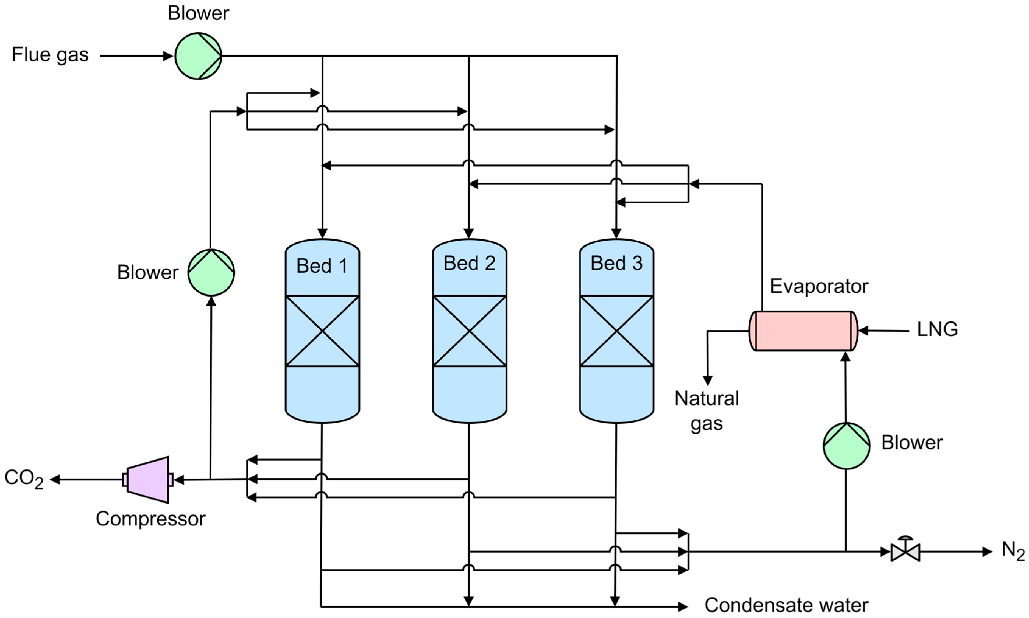
3.1. Dynamic Packed Bed

The concept of using cryogenic packed beds operated cyclically to capture CO2 from flue gases was first introduced by Tuinier et al. [29]. According to this method, CO2, H2O, and atmospheric gases (N2, O2, Ar) can be effectively separated on the basis of the differences in their dew and sublimation points. Furthermore, disadvantages related to frost clogging, high-pressure drops, the use of chemical sorbents and elevated operational pressures can all be avoided. To allow a continuous separation, Tuinier et al. [56] designed a three-bed, three-step cycle configuration consisting of a cooling, a capture, and a recovery step, similar to a conventional cyclic adsorption-based process [57]. In the cooling step, the bed is cryogenically cooled down to −120 °C with the aid of cold energy provided by the vaporization of LNG. In the capture step, the feed gas is passed through the bed where H2O and CO2 condensate and sublimate, respectively, on the bed packing while supercritical N2 leaves the bed outlet. Then, in the recovery step, CO2 and H2O are recovered via a co-current purging stream of pure CO2 and air, respectively. The process flow diagram of the cryogenic packed bed is reported in Figure 6. The same authors [29,56] studied the evolution of concentration and temperature profiles along the bed axial dimension with experiments and dynamic simulations using a 1D pseudo-homogeneous model. It was found that starting from a flue gas containing 10 mol% CO2 and 1 mol% H2O (balanced with N2) at atmospheric pressure, the required cold duty to carry out the separation was 1.8 MJ kgCO2−1. In follow-up work, Tuinier et al. [58] performed a techno-economic assessment of the cryogenic packed bed-based technology. The influence of several parameters was investigated, including the initial bed temperature, the feed CO2 concentration, and the resulting pressure drops. Compared with other carbon capture methods, this technology was found to experience greater heat losses and to rely heavily on the availability of cold utilities. In the above works, the employed packing material was a steel monolith structure; however, Lively et al. [59] proposed to the use of fibrous packing in order to increase the contact area and reduce the purging gas pressure drops along the bed. It was claimed that these fibrous materials have the potential to foster the scale-up of this technology from both capital and operational cost perspectives.
A major limitation of this technology is that the process output is a gaseous stream of CO2 that must be returned to the liquid phase for transportation and storage, therefore, losing the advantage of avoiding the liquefaction cost. Other limitations in the use of fixed packed beds are that the CO2 frost can accumulate in the bed during the capture step, thus hindering the heat transfer efficiency and the need for multiple beds to be operated cyclically. To overcome these issues, Willson et al. [60] introduced the moving packed bed technology where the CO2 frost is removed more efficiently from the capture bed and is recirculated for pre-cooling purposes. The process was modeled using Aspen Plus software for flue gases having a CO2 concentration in the range of 5–35 mol%. The cryogenic moving bed technology showed significantly lower CO2 capture costs than the conventional amine-based absorption process for small-scale applications. In subsequent works, Cann et al. [61,62] conducted experimental works to assess the behavior of temperature profiles within the moving packed beds. The key findings were: (i) the CO2 frost accumulation front can be controlled in the capture bed under appropriate conditions; (ii) high-density ceramic packing allowed higher front velocities than steel-based packing; (iii) bed pre-cooling and CO2 capture steps can be operated simultaneously. In addition, the design of cryogenic moving beds could be optimized by incorporating appropriate energy balance models involving CO2 desublimation for various gas feed flowrates and compositions, as recently investigated by Cann and Font-Palma [63].

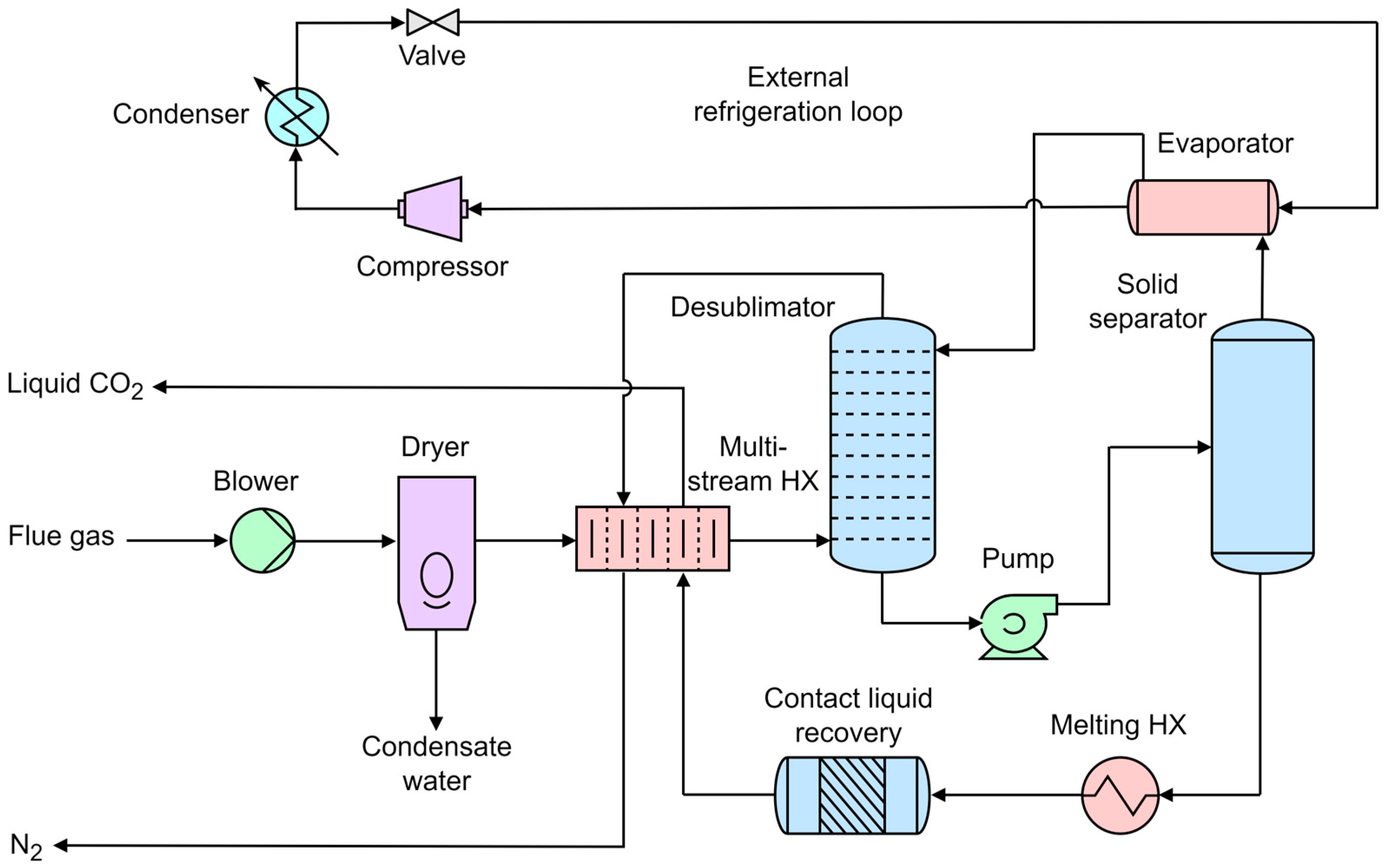
3.2. External Cooling Loop

Since 2008, Sustainable Energy Solutions has developed a cryogenic carbon capture process based on a minimally invasive bolt-on technology for post-combustion able to reuse waste cold energy using an external cooling loop [64]. This method features additional benefits, such as reduced compression power, water savings and simultaneous treatment of pollutants (SOX, NOX, HCl). In the original process configuration [40], the flue gas is initially dried and cooled to a temperature just above the CO2 freezing point through an external refrigerant loop. The CO2 is then expanded for further cooling and desublimated in a gas–solid separator. The solid CO2 is eventually liquefied by exchanging heat with the incoming feed. However, the process was improved by Jensen et al. [30], as reported in Figure 7. After drying, the flue gas enters a multi-stream heat exchanger where its temperature is lowered to −98 °C. The flue gas is then further cooled to −119 °C in a staged column with direct cryogenic liquid contact, causing CO2 to desublimate. The resulting slurry of solid CO2 and contacting liquid is sent to a separator, after which the dry ice is melted in the multi-stream heat exchanger to provide liquid CO2. The melting heat exchanger is also integrated to recover the cold thermal duty. On the other side, the contacting liquid stream is cooled by an LNG-based external refrigeration loop and sent back to the staged column. According to the authors’ simulation results (Jensen et al. [30]), this technology could recover 90% of CO2 with an energy consumption of 0.74 MJe kgCO2−1 when retrofitted to a 550 MWe coal-fired power plant. In addition, a recent patent [65] disclosed an invention to further improve the energy efficiency of the process by using multiple external cooling loops and matching the temperature profiles between the condensable vapor and the refrigerant up to temperature differences of less than 1 °C. It was also reported [66] that the external cooling loop technology has the capability of storing energy in the form of LNG, allowing it to shift the parasitic losses during peak hours and regenerate the refrigerant during low-demand periods. The cryogenic carbon capture process could thus be optimized within a hybrid energy system, coupling both conventional and renewable power generation units.
A strong advantage of the external cooling loop technology is that it has been successfully tested on real flue gas slip streams from coal, biomass, natural gas, and municipal waste fuels at various field sites in Utah and Wyoming, USA, including utility power stations, heating plants, and cement kilns [64]. The CO2 concentration in the feed ranged from 5 to 22 mol% on a dry basis, while the CO2 recoveries were between 90 and 99%. In a recent technical report by Sustainable Energy Solutions [67], it was claimed that multiple tests using the flue gas at the Hunter power plant exceeding 35 h were completed, with a total of over 600 h of CO2 capture with an average CO2 recovery of over 91%.

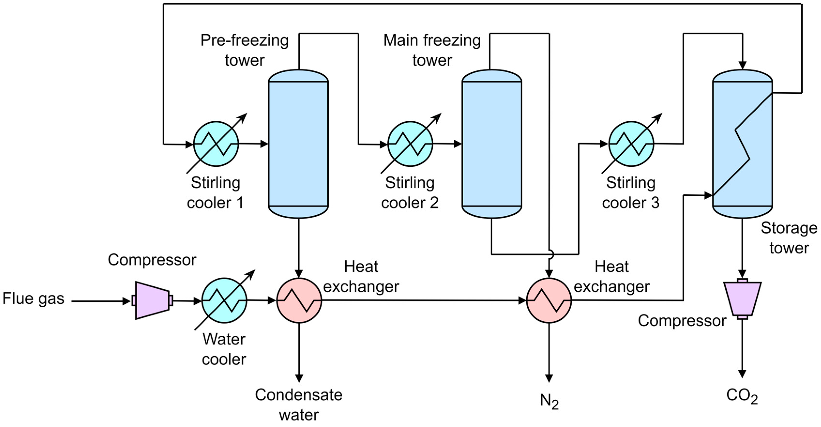
3.3. Stirling Cooler

Free piston Stirling coolers are a new type of cryogenic cooler attracting interest due to their high energy efficiency and operation reliability. Different from conventional coolers, they could be regenerated using helium or hydrogen as working fluids, thus avoiding the use of environmentally harmful gases such as CFCs and HCFCs [68]. Because of these advantages, Song et al. [69] proposed to incorporate the Stirling coolers within the cryogenic post-combustion capture process. The process flow diagram coupled with heat integration is shown in Figure 8. The system is composed of three sections, namely the pre-freezing tower, main freezing tower, and storage tower, each of which is refrigerated using a Stirling cooler. The flue gas is compressed and, after recovering heat from the outgoing process streams, is sent to the pre-freezing tower, where the temperature is controlled by the first Stirling cooler. In this tower, water is removed from the flue gas by condensation. The dry flue gas is then passed through the main freezing tower, where additional heat is removed by the second Stirling cooler until the temperature reaches –140 °C. At this point, CO2 desublimates, and the solid dry ice is scraped down by a rod to gather on the storage tower (refrigerated by the third Stirling cooler). Eventually, the CO2-lean flue gas leaves the top of the main freezing tower while the captured CO2 is collected at the bottom of the storage tower (Figure 8).
The cryogenic CO2 capture process based on free piston Stirling coolers has been extensively assessed both numerically and experimentally. In particular, Song et al. [70] carried out a detailed parametric analysis on a mathematical model coupling mass and energy balances. They investigated the influence of various parameters on the CO2 capture rate and energy consumption, including the ambient temperature, the vacuum condition on the interlayer, the idle operating time, the flue gas flowrate, and the Stirling cooler temperatures. The system was further optimized using a surface response methodology on the basis of experimental data fitting to a second-order polynomial and an analysis of variance (ANOVA). It was found that the optimal process could achieve 95% of the CO2 capture rate with a specific energy consumption of 0.55 MJe kgCO2−1 [71]. These results were also fully confirmed experimentally using a lab-scale apparatus considering a reference flue gas flowrate of 5 L min−1 at atmospheric pressure [72]. In order to enhance the cryogenic CO2 capture efficiency, Song et al. [68] studied the coefficient of performance (COP) of the Stirling coolers in a follow-up experimental work. According to the key findings, the COP could be increased to a value of 0.82 by designing short and thick cold heads and using copper as a material for construction. More recently, an advanced cryogenic CO2 capture process based on Stirling coolers was also simulated and optimized using heat integration using Aspen Plus software. It was concluded that only two Stirling coolers would be required in the system, while the energy consumption could be reduced by 45.1% when applying the process to the flue gas of a conventional 600 MW coal-fired power plant [73].
Figure 8. Process flow diagram of the Stirling cooler technology [73].
Energies 17 02673 g008

3.4. Antisublimation (AnSU)

The first cryogenic process based on desublimation was developed by Clodic and Younes [74], who aimed to capture CO2 by freezing it on the cold surfaces of low-temperature evaporators. The authors proposed a thermodynamic cycle considering the variation of CO2 freezing temperature at atmospheric pressure as a function of the CO2 concentration in the feed. For instance, with initial concentrations of 15 mol% and 1 mol%, the freezing temperatures are around −100 °C and −122 °C, respectively [75]. The patented process was called Antisublimation (AnSU) [76] and consisted of five steps, as presented in Figure 9. The flue gas is first sent to three condensers in series, where it is ultimately cooled down to −40 °C for water removal. On the other hand, the CO2-lean flue gas is recirculated through three evaporators in a series designed for heat integration. Further heat is also recovered in the pre-cooler, where the dry flue gas temperature is lowered to −100 °C by exchanging heat with the cold CO2-lean flue gas. An LNG-based refrigeration integrated cascade (RIC) equipped with a single compressor and integrated with the water-cooling loop provides cold energy duty to the desublimation unit through the evaporation of the refrigerant blend occurring between −120 °C and −100 °C. In the desublimator, CO2 is captured as dry ice with a temperature glide corresponding to the decrease of CO2 concentration in the flue gas associated with the capture process. A CO2 recovery system inside the desublimator allows for the recovery of the heat of fusion and some heat of sublimation of CO2 so that both liquid CO2 and gaseous CO2 are produced and collected in a downstream tank (Figure 9).
The AnSU process was extensively assessed both theoretically and experimentally. Clodic et al. [77] studied the COP of the RIC of a post-combustion CO2 capture process applied to a pulverized coal-fired power plant. It was found that with an initial CO2 concentration of 10% in the feed and a CO2 recovery of 90%, the specific energy consumption ranged between 0.65 and 1.25 MJe kgCO2−1, depending on the cooling system efficiency. Pan et al. [54] improved the calculations concerning the energy penalty incurred by a 900 MW coal-fired power plant considering all electrical equipment along with the CO2 compression power. The resulting energy consumption associated with the anti-sublimation process was 1.18 MJe kgCO2−1 for a CO2 initial concentration of 12% and a CO2 capture rate of 90%. These theoretical results were also confirmed by experimental tests on a mock-up of 2.5 kW cooling capacity at −120 °C running for 4000 h and capturing 150 kg of CO2 per day [54,75]. Due to the cryogenic temperature range of operation of the AnSU process, even a slight increase in the temperature of the cold refrigerant may result in a significant reduction in the overall energy consumption of the system. For this reason, Hees and Monroe [78] disclosed the idea of carrying out the desublimation step at a higher pressure than atmospheric pressure, in the range of 1.5–10 bar. It was claimed that this would allow an increase in the refrigerant temperature while still retaining the CO2 capture efficiency.

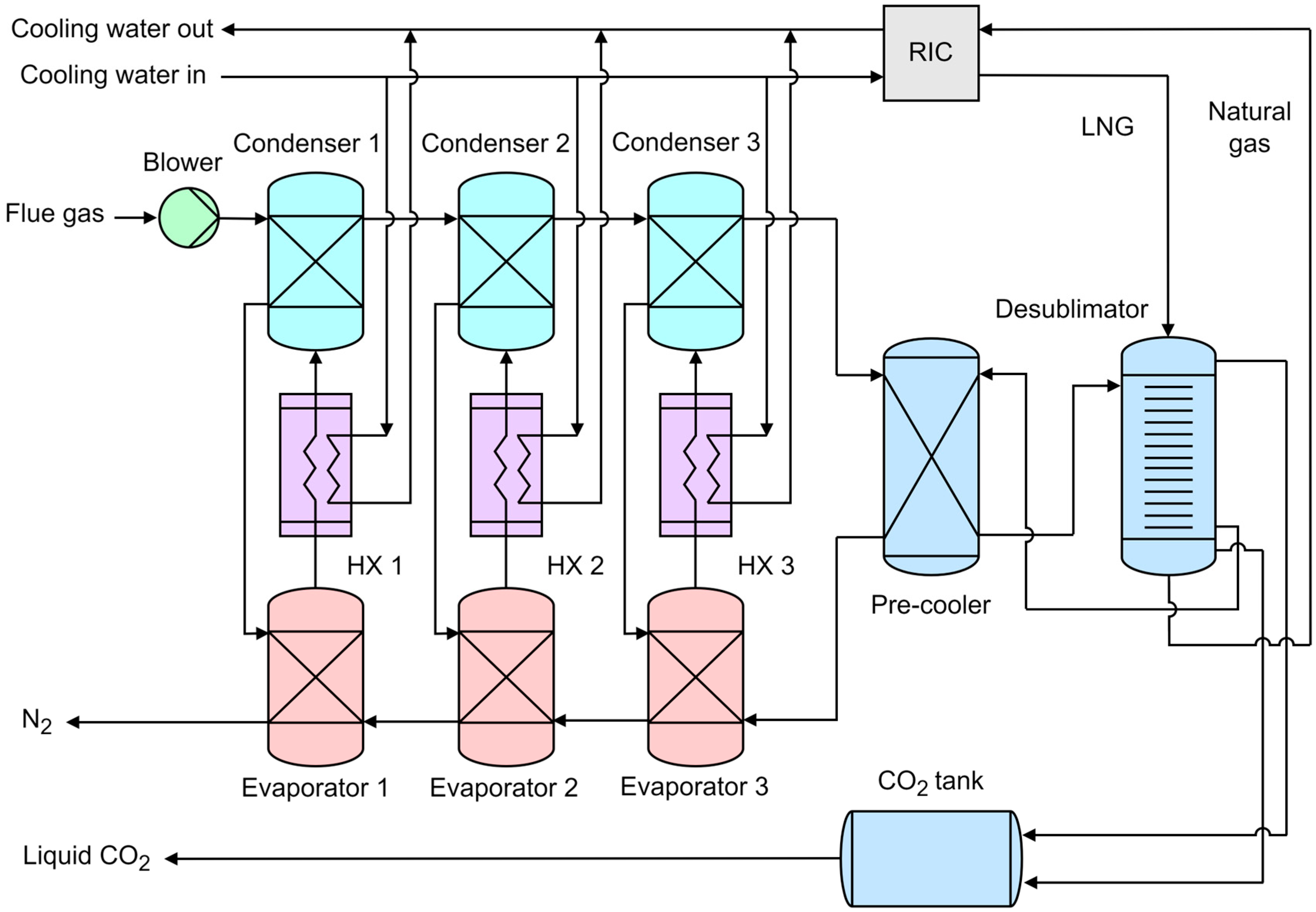
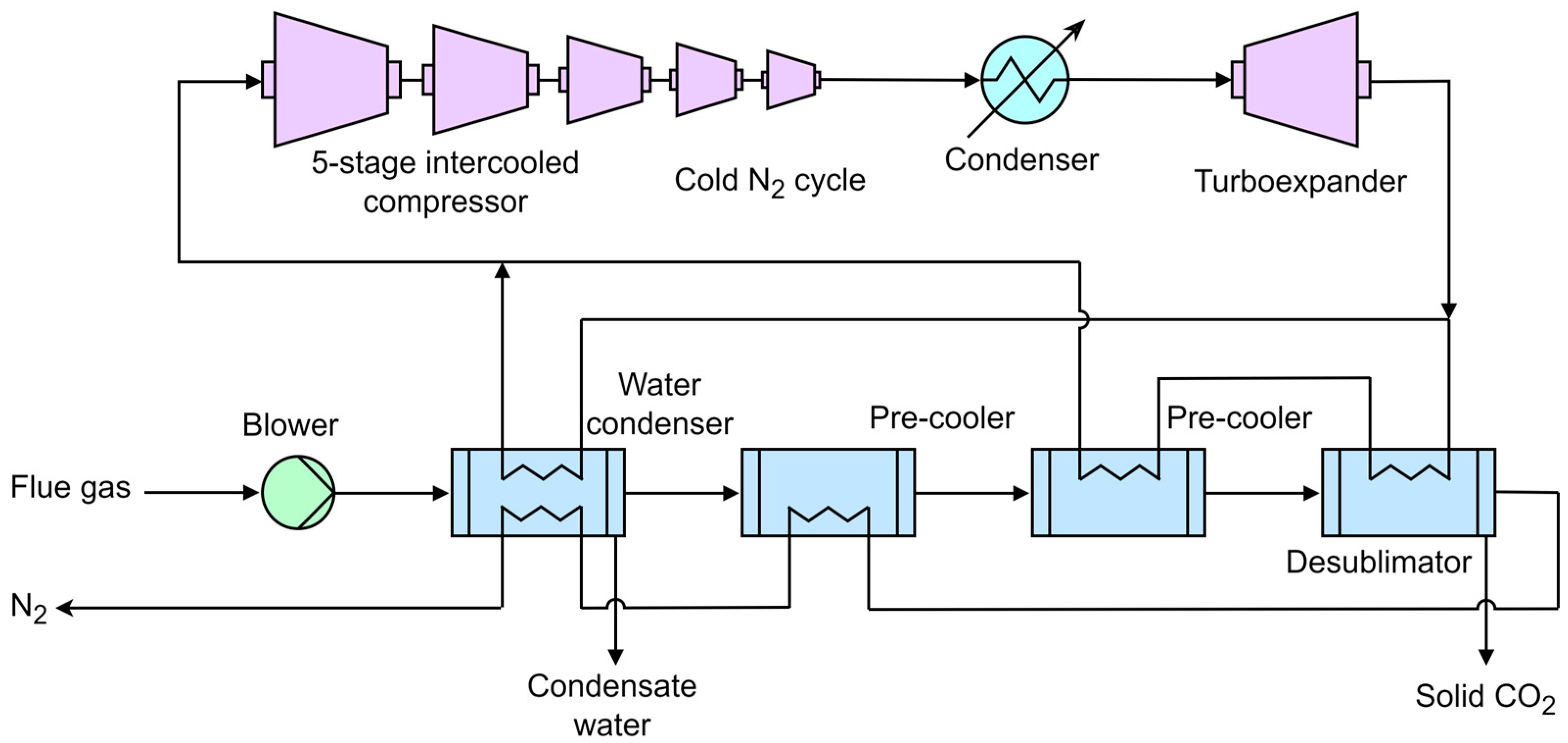
3.5. Novel Low-Cost CO2 Capture Technology (NLCCT)

De and Oduniyi [79] recently disclosed a cryogenic CO2 post-combustion capture technology called NLCCT, characterized by low cost and low water consumption. This method features the simultaneous removal of all typical flue gas pollutants (SOX, NOX, HCl, CO, Hg, ashes, etc.), the use of cold nitrogen gas as refrigerant, the use of turbine expansion work to drive some of the compressor shafts, and some efficiently constructed cooling chambers to pre-cool and desublimate CO2. The process flow diagram of the NLCCT technology is exhibited in Figure 10. The cold N2 gas is produced in a refrigeration cycle where N2 at ambient conditions is first sent to a five-stage intercooled compressor to raise its pressure to 25–40 atm. After being cooled down to 37 °C in a condenser, the N2 is then expanded in a turboexpander to 1 atm, where it cools down to the desired temperature range of −175/−102 °C. This cold N2 stream, along with the recirculated CO2-lean flue gas, will provide the cold duties to the water condenser, the pre-coolers and the desublimator, as illustrated in Figure 10. On the other side, the flue gas is first passed through a water condenser, allowing the removal of H2O, and then is directed to two pre-coolers where its temperature is lowered just above the CO2 freezing point, thus preventing premature CO2 desublimation that could cause fouling. Eventually, upon further cooling, CO2 is recovered in the solid state at the bottom of the desublimation chamber while the CO2-lean flue gas leaves at the top of the chamber.
De et al. [80] performed an in-depth modeling assessment of the NLCCT process applied to natural gas-fired combined cycle power plants, evaluating several parameters such as CO2 concentration in the feed, ambient temperature, compression temperatures and pressure ratios. With a CO2 concentration in the feed of 6.7 mol%, the system achieved a CO2 capture efficiency of 99%, along with a specific energy consumption of 0.63 MJe kgCO2−1.

3.6. Comparison of Cryogenic Desublimation Processes

The main advantages and challenges of the cryogenic processes by desublimation for post-combustion carbon capture described in the previous sub-sections are reported in Table 2. It is clear from the table that apart from the AnSU process, all technologies can treat wet flue gases, some of them even showing the capability of removing other pollutants. In addition, the external cooling loop, the Stirling cooler and the NLCCT process feature energy storage and/or water-saving potentials. At the same time, only the external cooling loop and the AnSU process have been tested on a pilot plant scale, while the other technologies are only limited to lab-scale demonstrations and/or numerical studies. Because of the high energy requirements of cryogenic processes, their installation is usually restricted by the availability of cold energy sources, especially LNG for dynamic packed beds and AnSU, which, in turn, are subject to the scale, location, and other specifications of the natural gas plants. Although less cost-effective, compression and refrigeration are a common method for providing the cold energy duties, which should ideally be integrated with recuperative heat exchangers to recover sensible and latent heat from residual streams and the liquefaction of solid CO2 (Stirling cooler, NLCCT). Furthermore, most technologies suffer from heat losses due to CO2 frost accumulation during desublimation [31].
Table 3 summarizes the separation performances of the cryogenic CO2 capture processes by desublimation. Although the processes cannot be directly compared due to the different CO2 concentrations in the feed and the CO2 recoveries achieved, the Stirling cooler and the NLCCT process seem more promising, with specific energy consumptions in the range of 0.55–0.63 MJe kgCO2−1. However, the results from the external cooling loop and AnSU technologies should provide once again a better indication of the energy consumption figures (0.74–1.18 MJe kgCO2−1), as they were tested on a pilot plant scale. It should be noted that all cryogenic processes in Table 3 were compared based on electrical energy consumption, where the conversion ratio between thermal and electrical energy is around 0.5 for this kind of applications [56].

4. Conclusions and Technological Challenges

This review presented the main process schemes related to cryogenic desublimation also providing the fundamental thermodynamic and mass transfer aspects to understand the peculiarities and potentialities of this carbon capture strategy.
Cryogenic carbon capture by desublimation has emerged in the last two decades as a promising carbon capture technology due to the strong advances in the process configurations aimed to maximize energy recovery and decrease overall costs. In particular, the external cooling loop and AnSU technologies have been tested on the pilot plant level and reported energy consumptions in the range of 0.74–1.18 MJe kgCO2−1. In addition, detailed modeling works based on the Stirling cooler and NLCCT process claimed even lower energy consumption and, thus, overall costs. These processes can easily capture above the industry standard (90%), with some additional peculiarities:
  • Reduced water (and steam) consumption
  • Possibility of coupling with large-scale energy storage (with benefit for grid stabilization)
  • Solutions as bolt-on retrofit technology or as an integrated system.
  • Possibility of ancillary pollutants’ separation (such as SOx, NOx, and Hg): in this way, a green-field, fully integrated plant can redirect the capital, operating cost, and footprint resources currently dedicated to pollutant control and redirect these toward the carbon capture system.
While from the point of view of separation and energy efficiency, cryogenic capture seems to excel, there are still technological problems that have slowed down demonstration programs and tend to increase implementation costs. Main technological issues are related to the following:
  • Material Challenges and Extreme Temperatures: From the point of view of durability, cryogenic temperatures can cause materials to become brittle and prone to failure, necessitating the use of specialized materials. Repeated cooling and heating cycles can lead to material fatigue and failure over time. The austenitic stainless steels such as 304 and 316 (an alloy with at least 9% nickel) retain their engineering properties at cryogenic temperatures and are commonly used for transport and storage of cryogenic liquids. Aluminum and aluminum alloys can be suitable for extreme cold scenarios, too, since they exhibit very good stability against temperature variations, and some of them even show an increase in ultimate tensile strength and fracture toughness. On the other hand, the insulation system is fundamental for cryogenic applications to avoid energy losses and to prevent accidents and/or external water vapor desublimation. The insulation types and materials are chosen based on their thermal performance and mechanical properties. The insulation systems can be made of foam and fibrous, multilayers, and vacuum jacketed systems. Materials implemented for this purpose are fiberglass, mineral wool, aerogel composite, and powder and granular. Perlite and Hollow glass or ceramic microspheres are often implemented to fill spaces between vacuum walls in insulating cryogenic vessels. For example, the equipment of the cited pilot plants was often installed in a cold box filled with perlite or glass powder insulation and vacuum-jacketed tubing was realized for some of the key fluid transfer lines; at small scales, the main equipment is placed inside blankets of gray fiberglass insulation.
  • Technological Readiness and Cost: Assessing the economic viability of cryogenic carbon capture and identifying strategies to reduce costs are critical knowledge gaps. Research should focus on the development of cost-effective materials and innovative engineering solutions at cryogenic conditions to enhance the overall economic feasibility. This should include the insulation materials and ancillary equipment. Among the process equipment characterizing cryogenic carbon capture, there are some critical apparatuses such as solid–liquid separation (e.g., screw press and centrifugal separators), dehydrator systems for water vapor removal, cryogenic distillation to reduce impurities, and losses in closed cycle (direct-contact) heat transfer configurations, as well as slurry pumps, packed beds, bubble columns and turboexpanders. Continued innovation is needed to overcome current technological barriers, but this requires sustained investment and research. Many cryogenic carbon capture technologies are still in the developmental or pilot stages, with limited real-world deployment; transitioning from laboratory or pilot-scale systems to full-scale industrial applications presents significant engineering challenges. For example, the processes of start-up and shut-down, as well as the process control (maintaining precise control over temperature and pressure within the cryogenic system), are technically demanding. Moreover, handling cryogenic fluids poses safety risks, including frostbite, asphyxiation, and equipment failure. The research group that first made these steps forward is that of Baxter et al. [30,40,64,65,66,67], which recently published industrial data for a medium-sized pilot plant (around a few tons of CO2 per day). They also produced a techno-economic analysis to compare the economic performances against the baseline for fossil energy plants. The estimated cost of CO2 avoidance is below USD 40 per ton, and LCOE is around USD 9 per kWh. Recently, similar values (even lower) were disclosed by De et al. [80] for their system. Their results overcame the ones reported by the group of Tuinier at al. [58], who compared the economics of their innovative cryogenic packed bed to the performances of absorption and membrane technology.
Addressing these technological issues is crucial for the successful implementation and scaling of cryogenic carbon capture solutions. Ongoing research and development, along with collaborative efforts across industry and academia, are essential to overcoming these challenges. At the same time, several knowledge gaps and research needs must be addressed in order to achieve process optimization. The operating conditions, including temperature ranges, pressure levels, and heat integration (even in co-generation process schemes), can be further optimized. Efficient heat integration within the process is crucial to minimize energy losses and overall energy consumption. Understanding how these processes can be effectively integrated into various industrial systems (e.g., LNG regasification) is another key research aspect. This encompasses the retrofit with various industries, identifying potential synergies and addressing engineering challenges. Moreover, investigating the safety aspects and potential risks associated with cryogenics is paramount.
Although cryogenic carbon capture aims to reduce CO2 emissions, the overall environmental footprint of the process, including energy use and potential leaks, must be considered. A comprehensive assessment of the environmental impact of CCC is necessary. This should involve evaluating the overall carbon footprint of the technology, including indirect emissions associated with equipment production, transportation, and other life cycle stages. On the other hand, these processes contain equipment familiar to end users, such as power and industrial consumers (e.g., refrigeration systems, heat exchangers, processing vessels) with commonly implemented materials. This, combined with the substantial energy savings, the reduction of water footprint, and the limited impact on critical raw materials, suggests that cryogenic desublimation technologies will also achieve better “over the life cycle” results than their competitors.

Author Contributions

Conceptualization, M.C. and M.L.; methodology, M.C. and M.L.; data curation, M.C., E.B. and M.L.; writing—original draft preparation, M.C., E.B. and M.L.; writing—review and editing, M.C., E.B. and M.L. All authors have read and agreed to the published version of the manuscript.

Funding

This research received no external funding.

Data Availability Statement

No new data were created or analyzed in this study. Data sharing is not applicable to this article.

Conflicts of Interest

The authors declare no conflicts of interest.

Nomenclature

Acronyms
AnSUAntisublimation
BECCSBioenergy with carbon capture and storage
CCCCryogenic carbon capture
CCSCarbon capture and storage
CCUCarbon capture and utilization
CCUSCarbon capture, utilization and storage
COPCoefficient of performance
DACDirect air capture
EoSEquation of state
NLCCTNovel low-cost CO2 capture technology
PSAPressure swing adsorption
RICRefrigeration integrated cascade
SMRSteam methane reforming
SVESolid-vapor equilibrium
SLVESolid-liquid-vapor equilibrium
TRLTechnology readiness level
TSATemperature swing adsorption
SymbolsUnitDescription
a ( T ) Pa m6 mol−2Energy parameter in cubic EoS
b m3 mol−1Covolume in cubic EoS
h G W m−2 K−1Heat transfer coefficient of the gas phase
h L W m−2 K−1Heat transfer coefficient of the liquid phase
k Y kg m−2 s−1Mass transfer coefficient of the gas phase
n f C O 2 molMoles of CO2 in the feed
n p 1 C O 2 molMoles of CO2 in the product 1
n 2 C O 2 molMoles of CO2 in the product 2
n f i n e r t molMoles of inert in the feed
n p 1 i n e r t molMoles of inert in the product 1
n p 2 i n e r t molMoles of inert in the product 2
P PaTotal pressure
P C O 2 S PaSublimation vapor pressure of CO2
P i n PaInitial pressure of compression
P o u t PaFinal pressure of compression
Q ˙ c o n d WThermal duty of condensation
Q s e p kJ kg−1Specific thermal duty of separation
q s G W m−2Sensible heat flux of the gas phase
q λ G W m−2Latent heat flux of the gas phase
q s L W m−2Sensible heat flux of the liquid phase
R J mol−1 K−1Ideal gas constant
S m2Interface surface
T KTemperature
T 0 KAmbient temperature
T c o n d KTemperature of liquefaction
T G KTemperature of the gas phase
T i KTemperature of the interphase
T L KTemperature of the liquid phase
T s e p KTemperature of the hot source used for separation
v m3 mol−1Molar volume in cubic EoS
v C O 2 S m3 mol−1Molar volume of solid CO2
W c o m p m i n kJ kgCO2−1Minimum work rate of compression
W c o m p kJ kgCO2−1Actual work of compression
W c o n d m i n kJ kgCO2−1Minimum work of liquefaction
W c o n d kJ kgCO2−1Actual work of liquefaction
W s e p m i n kJ kgCO2−1Minimum work of separation
W s e p kJ kgCO2−1Actual work of separation
y C O 2 Mole fraction of CO2 in the vapor phase
y C O 2 , i Mole fraction of CO2 in the interface
y f C O 2 Mole fraction of CO2 in the feed
y p 1 C O 2 Mole fraction of CO2 in the product 1
y 2 C O 2 Mole fraction of CO2 in the product 2
y f i n e r t Mole fraction of inert in the feed
y p 1 i n e r t Mole fraction of inert in the product 1
y p 2 i n e r t Mole fraction of inert in the product 2
z mAxial dimension
Greek letters
η I I II law efficiency
λ C O 2 J kg−1Heat of liquefaction of CO2
ϕ C O 2 S Fugacity coefficient of CO2 at the saturated solid pressure
ϕ C O 2 V Fugacity coefficient of CO2 in the vapor phase

References

  1. IPCC. Summary for Policymakers. In Climate Change 2021: The Physical Science Basis. Contribution of Working Group I to the Sixth Assessment Report of the Intergovernmental Panel on Climate Change; Masson-Delmotte, V.P., Zhai, A., Pirani, S.L., Connors, C., Péan, S., Berger, N., Caud, Y., Chen, L., Goldfarb, M.I., Gomis, M., et al., Eds.; Cambridge University Press: Cambridge, UK; New York, NY, USA, 2021; pp. 3–32. [Google Scholar]
  2. Gabrielli, P.; Gazzani, M.; Mazzotti, M. The role of carbon capture and utilization, carbon capture and storage, and biomass to enable a net-zero-CO2 emissions chemical industry. Ind. Eng. Chem. Res. 2020, 59, 7033–7045. [Google Scholar] [CrossRef]
  3. Keyßer, L.T.; Lenzen, M. 1.5 °C degrowth scenarios suggest the need for new mitigation pathways. Nat. Commun. 2021, 12, 2676. [Google Scholar] [CrossRef] [PubMed]
  4. Bednar, J.; Obersteiner, M.; Baklanov, A.; Thomson, M.; Wagner, F.; Geden, O.; Allen, M.; Hall, J.W.A. Operationalizing the net-negative carbon economy. Nature 2021, 596, 377–383. [Google Scholar] [CrossRef]
  5. IEA. Energy Technology Perspectives, 2020. IEA, Paris. Available online: https://www.iea.org/reports/energy-technology-perspectives-2020 (accessed on 1 May 2024).
  6. Schmitt, T.; Homsy, S.; Mantripragada, H.; Woods, M.; Hoffman, H.; Shultz, T.; Fout, T.; Hackett, G. Cost and Performance of Retrofitting NGCC Units for Carbon Capture; U.S. Department of Energy Office of Scientific and Technical Information: Pittsburgh, PA, USA, 2023.
  7. Capocelli, M.; Luberti, M.; Inno, S.; D’Antonio, F.; Di Natale, F.; Lancia, A. Post-combustion CO2 capture by RVPSA in a large-scale steam reforming plant. J. CO2 Util. 2019, 32, 53–65. [Google Scholar] [CrossRef]
  8. Luberti, M.; Brown, A.; Balsamo, M.; Capocelli, M. Numerical analysis of VPSA technology retrofitted to steam reforming hydrogen plants to capture CO2 and produce blue H2. Energies 2022, 15, 1091. [Google Scholar] [CrossRef]
  9. Luberti, M.; Ahn, H. Review of Polybed pressure swing adsorption for hydrogen purification. Int. J. Hydrogen Energy 2022, 47, 10911–10933. [Google Scholar] [CrossRef]
  10. Barba, D.; Brandani, F.; Capocelli, M.; Luberti, M.; Zizza, A. Process analysis of an industrial waste-to-energy plant: Theory and experiments. Process Saf. Environ. Prot. 2015, 96, 61–73. [Google Scholar] [CrossRef]
  11. Butnar, I.; Cronin, J.; Pye, S. Review of Carbon Capture Utilisation and Carbon Capture and Storage in Future EU Decarbonisation Scenarios; Final Report Prepared for The Carbon Capture and Storage Association; UCL Energy Institute: London, UK, 2020. [Google Scholar]
  12. Koelbl, B.S.; van den Broek, M.; Faaij, A.P.C.; van Vuuren, D.P. Uncertainty in Carbon Capture and Storage (CCS) deployment projections: A cross-model comparison exercise. Clim. Chang. 2014, 123, 461–476. [Google Scholar] [CrossRef]
  13. Capocelli, M.; De Falco, M. Generalized penalties and standard efficiencies of carbon capture and storage processes. Int. J. Energy Res. 2022, 46, 4808–4824. [Google Scholar] [CrossRef]
  14. Sifat, N.S.; Yousef, H. A critical review of CO2 capture technologies and prospects for clean power generation. Energies 2019, 12, 4143. [Google Scholar] [CrossRef]
  15. Kearns, D.; Liu, H.; Consoli, C. Technology Readiness and Costs of CCS. Global CCS Institute, 2021; Available online: https://www.globalccsinstitute.com/wp-content/uploads/2021/03/Technology-Readiness-and-Costs-for-CCS-2021-1.pdf (accessed on 27 May 2024).
  16. Ahn, H.; Luberti, M.; Liu, Z.; Brandani, S. Process simulation of aqueous MEA plants for post-combustion capture from coal-fired power plants. Energy Procedia 2013, 37, 1523–1531. [Google Scholar] [CrossRef]
  17. Erto, A.; Silvestre-Albero, A.; Silvestre-Albero, J.; Rodríguez-Reinoso, F.; Balsamo, M.; Lancia, A.; Montagnaro, F. Carbon-supported ionic liquids as innovative adsorbents for CO₂ separation from synthetic flue-gas. J. Colloid. Interface Sci. 2015, 15, 41–50. [Google Scholar] [CrossRef] [PubMed]
  18. Luberti, M.; Oreggioni, G.D.; Ahn, H. Design of a rapid vacuum pressure swing adsorption (RVPSA) process for post-combustion CO2 capture from a biomass-fuelled CHP plant. J. Environ. Chem. Eng. 2017, 5, 3973–3982. [Google Scholar] [CrossRef]
  19. Luberti, M.; Ahn, H. Design of an industrial multi-bed (V)PSA unit for argon concentration. Sep. Purif. Technol. 2021, 261, 118254. [Google Scholar] [CrossRef]
  20. Brunetti, A.; Scura, F.; Barbieri, G.; Drioli, E. Membrane technologies for CO2 separation. J. Membr. Sci. 2010, 359, 115–125. [Google Scholar] [CrossRef]
  21. Font-Palma, C.; Cann, D.; Udemu, C. Review of cryogenic carbon capture innovations and their potential applications. J. Carbon Res. 2021, 7, 58. [Google Scholar] [CrossRef]
  22. Swanson, C.E.; Elzey, J.W.; Hershberger, R.E.; Donnelly, R.J.; Pfotenhauer, J. Thermodynamic analysis of low-temperature carbon dioxide and sulfur dioxide capture from coal-burning power plants. Phys. Rev. E 2012, 86, 016103. [Google Scholar] [CrossRef] [PubMed]
  23. Holmes, S.; Ryan, J.M. Cryogenic Distillative Separation of Acid Gases from Methane. US Patent 4,318,723, 9 March 1982. [Google Scholar]
  24. Hart, A.; Gnanendran, N. Cryogenic CO2 capture in natural gas. Energy Procedia 2009, 1, 697–706. [Google Scholar] [CrossRef]
  25. Yousef, A.M.; El-Maghlany, W.M.; Eldrainy, Y.A.; Attia, A. New approach for biogas purification using cryogenic separation and distillation process for CO2 capture. Energy 2018, 156, 328–351. [Google Scholar] [CrossRef]
  26. Shen, M.; Tong, L.; Yin, S.; Liu, C.; Wang, L.; Feng, W.; Ding, Y. Cryogenic technology progress for CO2 capture under carbon neutrality goals: A review. Sep. Purif. Technol. 2022, 299, 121734. [Google Scholar] [CrossRef]
  27. Berstad, D.; Skaugen, G.; Roussanaly, S.; Anantharaman, R.; Nekså, P.; Jordal, K.; Trædal, S.; Gundersen, T. CO2 capture from IGCC by low-temperature synthesis gas separation. Energies 2022, 15, 515. [Google Scholar] [CrossRef]
  28. Eide, L.I.; Anheden, M.; Lyngfelt, A.; Abanades, C.; Younes, M.; Clodic, D.; Bill, A.A.; Feron, P.H.M.; Rojey, A.; Giroudiere, F. Novel capture processes. Oil Gas Sci. Technol. 2005, 60, 497–508. [Google Scholar] [CrossRef]
  29. Tuinier, M.J.; van Sint Annaland, M.; Kramer, G.J.; Kuipers, J.A.M. Cryogenic CO2 capture using dynamically operated packed beds. Chem. Eng. Sci. 2010, 65, 114–119. [Google Scholar] [CrossRef]
  30. Jensen, M.J.; Russell, C.S.; Bergeson, D.; Hoeger, C.D.; Frankman, D.J.; Bence, C.S.; Baxter, L.L. Prediction and validation of external cooling loop cryogenic carbon capture (CCC-ECL) for full-scale coal-fired power plant retrofit. Int. J. Greenh. Gas Control 2015, 45, 200–212. [Google Scholar] [CrossRef]
  31. Song, C.; Liu, Q.; Deng, S.; Li, H.; Kitamura, Y. Cryogenic-based CO2 capture technologies: State-of-the-art developments and current challenges. Renew. Sustain. Energy Rev. 2019, 101, 265–278. [Google Scholar] [CrossRef]
  32. Asgharian, H.; Iov, F.; Araya, S.S.; Pedersen, T.H.; Nielsen, M.P.; Baniasadi, E.; Liso, V. A Review on process modeling and simulation of cryogenic carbon capture for post-combustion treatment. Energies 2023, 16, 1855. [Google Scholar] [CrossRef]
  33. Aneesh, A.M.; Sam, A.A. A mini-review on cryogenic carbon capture technology by desublimation: Theoretical and modeling aspects. Front. Energy Res. 2023, 11, 1167099. [Google Scholar] [CrossRef]
  34. Yang, W.; Li, S.; Li, X.; Liang, Y.; Zhang, X. Analysis of a new liquefaction combined with desublimation system for CO2 separation based on N2/CO2 phase equilibrium. Energies 2015, 8, 9495–9508. [Google Scholar] [CrossRef]
  35. De Guido, G.; Langè, S.; Moioli, S.; Pellegrini, L.A. Thermodynamic method for the prediction of solid CO2 formation from multicomponent mixtures. Process Saf. Environ. Prot. 2014, 92, 70–79. [Google Scholar] [CrossRef]
  36. De Guido, G.; Pellegrini, L.A. Phase equilibria analysis in the presence of solid carbon dioxide. Chem. Eng. Trans. 2021, 86, 1261–1266. [Google Scholar]
  37. Wang, J.; Wang, Z.; Sun, B. Improved equation of CO2 Joule–Thomson coefficient. J. CO2 Util. 2017, 19, 296–307. [Google Scholar] [CrossRef]
  38. Pellegrini, L.; De Guido, G.; Ingrosso, S. Thermodynamic Framework for Cryogenic Carbon Capture. In Proceedings of the 30th European Symposium on Computer Aided Process Engineering 2020 (ESCAPE30), Milano, Italy, 24–27 May 2020. [Google Scholar]
  39. Jensen, M. Energy Process Enabled by Cryogenic Carbon Capture. Ph.D. Thesis, BYU Theses and Dissertations, Brigham Young University, Provo, UT, USA, 2015. [Google Scholar]
  40. Baxter, L.; Baxter, A.; Burt, S. Cryogenic CO2 capture as a cost-effective CO2 capture process. In Proceedings of the International Pittsburgh Coal Conference, Pittsburgh, PA, USA, 20–23 September 2009. [Google Scholar]
  41. Yurata, T.; Lei, H.; Tang, L.; Lu, M.; Patel, J.; Lim, S.; Piumsomboon, P.; Chalermsinsuwan, B.; Li, C. Feasibility and sustainability analyses of carbon dioxide—Hydrogen separation via de-sublimation process in comparison with other processes. Int. J. Hydrogen Energy 2019, 44, 23120–23134. [Google Scholar] [CrossRef]
  42. Seader, J.D.; Henley, E. Separation Process Principles; John Wiley & Sons, Inc.: Hoboken, NJ, USA, 2006. [Google Scholar]
  43. Zonfrilli, M.; Facchino, M.; Serinelli, R.; Chesti, M.; De Falco, M.; Capocelli, M. Thermodynamic analysis of cold energy recovery from LNG regasification. J. Clean. Prod. 2023, 420, 138443. [Google Scholar] [CrossRef]
  44. House, K.Z.; Harvey, C.F.; Aziz, M.J.; Schrag, D.P. The Energy Penalty of Post-Combustion CO2 Capture & Storage and Its Implications for Retrofitting the U.S. Installed Base. Energy Environ. Sci. 2009, 2, 193. [Google Scholar]
  45. Bejan, A. Advanced Engineering Thermodynamics, 4th ed.; John Wiley & Sons, Inc.: Hoboken, NJ, USA, 2016. [Google Scholar]
  46. Yu, Z.; Miller, F.; Pfotenhauer, J.M. Numerical modeling and analytical modeling of cryogenic carbon capture in a de-sublimating heat exchanger. IOP Conf. Ser. Mater. Sci. Eng. 2017, 278, 012032. [Google Scholar] [CrossRef]
  47. Berger, A.H.; Hoeger, C.; Baxter, L.; Bhown, A.S. Evaluation of cryogenic systems for post combustion CO2 capture. In Proceedings of the 14th International Conference on Greenhouse Gas Control Technologies, GHGT-14, Melbourne, Australia, 21–25 October 2018. [Google Scholar]
  48. Cann, D.G. Experimental Exploration of Cryogenic CO2 Capture Utilising a Moving Bed. Ph.D. Thesis, The University of Chester, Chester, UK, 2021. [Google Scholar]
  49. James, D.W. Failing Drop CO2 Deposition (Desublimation) Heat Exchanger for the Cryogenic Carbon Capture Process. Ph.D. Thesis, Brigham Young University, Provo, UT, USA, 2011. [Google Scholar]
  50. Sun, B.; Ghatage, S.; Evans, G.M.; Bhatelia, T.; Utikar, R.P.; Pareek, V.K. Dynamic study of frost formation on cryogenic surface. Int. J. Heat Mass Transf. 2020, 150, 119372. [Google Scholar] [CrossRef]
  51. Wu, X.; Ma, Q.; Chu, F.; Hu, S. Phase change mass transfer model for frost growth and densification. Int. J. Heat Mass Transf. 2016, 96, 11–19. [Google Scholar] [CrossRef]
  52. Wu, X.M.; Webb, R.L. Investigation of the possibility of frost release from a cold surface. Exp. Therm. Fluid Sci. 2001, 24, 151–156. [Google Scholar] [CrossRef]
  53. Lei, T.; Luo, K.H.; Hernández Pérez, F.E.; Wang, G.; Wang, Z.; Cano, J.R.; Im, H.G. Study of CO2 desublimation during cryogenic carbon capture using the lattice Boltzmann method. J. Fluid Mech. 2023, 964, A1. [Google Scholar] [CrossRef]
  54. Pan, X.; Clodic, D.; Toubassy, J. CO2 capture by antisublimation process and its technical economic analysis. Greenh. Gas Sci. Technol. 2013, 3, 8–20. [Google Scholar] [CrossRef]
  55. Rezaei, S.; Liu, A.; Hovington, P. Emerging technologies in post-combustion carbon dioxide capture & removal. Catal. Today 2023, 423, 114286. [Google Scholar]
  56. Tuinier, M.J.; van Sint Annaland, M.; Kuipers, J.A.M. A novel process for cryogenic CO2 capture using dynamically operated packed beds—An experimental and numerical study. Int. J. Greenh. Gas Control 2011, 5, 694–701. [Google Scholar] [CrossRef]
  57. Luberti, M. Oxygen recovery from ozone generators by adsorption processes. Adsorption 2023, 29, 73–86. [Google Scholar] [CrossRef]
  58. Tuinier, M.J.; Hamers, H.P.; van Sint Annaland, M. Techno-economic evaluation of cryogenic CO2 capture—A comparison with absorption and membrane technology. Int. J. Greenh. Gas Control 2011, 5, 1559–1565. [Google Scholar] [CrossRef]
  59. Lively, R.P.; Koros, W.J.; Johnson, J.R. Enhanced cryogenic CO2 capture using dynamically operated low-cost fiber beds. Chem. Eng. Sci. 2012, 71, 97–103. [Google Scholar] [CrossRef]
  60. Willson, P.; Lychnos, G.; Clements, A.; Michailos, S.; Font-Palma, C.; Diego, M.E.; Pourkashanian, M.; Howe, J. Evaluation of the performance and economic viability of a novel low temperature carbon capture process. Int. J. Greenh. Gas Control 2019, 86, 1–9. [Google Scholar] [CrossRef]
  61. Cann, D.; Font-Palma, C.; Willson, P. Experimental analysis of CO2 frost front behaviour in moving packed beds for cryogenic CO2 capture. Int. J. Greenh. Gas Control 2021, 107, 103291. [Google Scholar] [CrossRef]
  62. Cann, D.; Font-Palma, C.; Willson, P. Moving packed beds for cryogenic CO2 capture: Analysis of packing material and bed precooling. Carbon Capture Sci. Technol. 2021, 1, 100017. [Google Scholar] [CrossRef]
  63. Cann, D.; Font-Palma, C. Evaluation of mathematical models for CO2 frost formation in a cryogenic moving bed. Energies 2023, 16, 2314. [Google Scholar] [CrossRef]
  64. Sayre, A.; Frankman, D.; Baxter, A.; Stitt, K. Field testing of cryogenic carbon capture. In Proceedings of the Carbon Management Technology Conference, Houston, TX, USA, 17–20 July 2017. [Google Scholar]
  65. Baxter, L. Systems and Methods for Separating Condensable Vapors from Light Gases or Liquids by Recuperative Cryogenic Process. US Patent No. US 10,724,793 B2, 28 July 2020. [Google Scholar]
  66. Safdarnejad, S.M.; Hedengren, J.D.; Baxter, L.L. Plant-level dynamic optimization of Cryogenic Carbon Capture with conventional and renewable power sources. Appl. Energy 2015, 149, 354–366. [Google Scholar] [CrossRef]
  67. Baxter, L.L.; Baxter, A.; Bever, E.; Burt, S.; Chamberlain, S.; Frankman, D.; Hoeger, C.; Mansfield, E.; Parkinson, D.; Sayre, A.; et al. Cryogenic Carbon Capture Development; Final Technical Report Submitted to US DoE NETL; National Energy Technology Laboratory: Pittsburgh, PA, USA, 2019.
  68. Song, C.; Lu, J.; Kitamura, Y. Study on the COP of free piston Stirling cooler (FPSC) in the anti-sublimation CO2 capture process. Renew. Energy 2015, 74, 948–954. [Google Scholar] [CrossRef]
  69. Song, C.; Kitamura, Y.; Li, S.; Ogasawara, K. Design of a cryogenic CO2 capture system based on Stirling coolers. Int. J. Greenh. Gas Control 2012, 7, 107–114. [Google Scholar] [CrossRef]
  70. Song, C.; Kitamura, Y.; Li, S.; Jiang, W. Parametric analysis of a novel cryogenic CO2 capture system based on Stirling coolers. Environ. Sci. Technol. 2012, 46, 12735−12741. [Google Scholar] [CrossRef] [PubMed]
  71. Song, C.; Kitamura, Y.; Li, S. Optimization of a novel cryogenic CO2 capture process by response surface methodology (RSM). J. Taiwan Inst. Chem. Eng. 2014, 45, 1666–1676. [Google Scholar] [CrossRef]
  72. Song, C.; Kitamura, Y.; Li, S.; Lu, J. Deposition CO2 capture process using a free piston Stirling cooler. Ind. Eng. Chem. Res. 2013, 52, 14936−14943. [Google Scholar] [CrossRef]
  73. Song, C.; Liu, Q.; Ji, N.; Deng, S.; Zhao, J.; Kitamura, Y. Advanced cryogenic CO2 capture process based on Stirling coolers by heat integration. Appl. Therm. Eng. 2017, 114, 887–895. [Google Scholar] [CrossRef]
  74. Clodic, D.; Younes, M. A new method for CO2 capture: Frosting CO2 at atmospheric pressure. Greenh. Gas Control Technol. 2003, I, 155–160. [Google Scholar]
  75. Clodic, D.; El Hitti, R.; Younes, M.; Bill, A.; Casier, F. CO2 capture by anti-sublimation: Thermo-economic process evaluation. In Proceedings of the 4th Annual Conference on Carbon Capture & Sequestration, Alexandria, VA, USA, 2–5 May 2005. [Google Scholar]
  76. Clodic, D.; Younes, M. Method and System for Extracting carbon Dioxide by Anti-Sublimation for Storage Thereof. US Patent No. 7,073,348 B2, 11 July 2006. [Google Scholar]
  77. Clodic, D.; Younes, M.; Bill, A. Test results of CO2 capture by anti-sublimation: Capture efficiency and energy consumption for boiler plants. Greenh. Gas Control Technol. 2005, II, 1775–1780. [Google Scholar]
  78. Hees, W.G.; Monroe, C.M. Method and System for Extracting Carbon Dioxide by Anti-Sublimation at RAISED Pressure. US Patent No. 8,163,070 B2, 24 April 2012. [Google Scholar]
  79. De, D.K.; Oduniyi, I.A. Highly Cost Effective Technology for Capture of Industrial Emissions without Reagent for Clean Energy and Clean Environment Applications. US Patent No. 10,670,334 B2, 2 June 2020. [Google Scholar]
  80. De, D.K.; Oduniyi, I.A.; Sam, A.A. A novel cryogenic technology for low-cost carbon capture from NGCC power plants for climate change mitigation. Therm. Sci. Eng. Prog. 2022, 36, 101495. [Google Scholar] [CrossRef]
Figure 1. (a) SVE calculations of CO2 recovery in the solid phase as a function of flue gas temperature for different pressures and inlet CO2 concentrations and (b) SVE calculations of flue gas temperature as a function of pressure for different CO2 recoveries in the solid phase. Simulation results obtained using the RGibbs reactor in Aspen Plus (lines) are compared to data from the literature (symbols) [38,40].
Energies 17 02673 g001
Figure 2. Minimum work of separation to obtain purified CO2 streams from a 15% CO2 feed stream as a function of CO2 recovery in the solid phase. The dotted lines represent the minimum work of separation only. Continuous lines represent the total minimum work of separation, including the work of CO2 compression and liquefaction.
Energies 17 02673 g002
Figure 3. Schematic of a cryogenic desublimator used for theoretical calculations [22].
Energies 17 02673 g003
Figure 4. Schematics of the film theory for gas desublimation in a mixture of non-condensable gases in countercurrent contact with a cold liquid.
Energies 17 02673 g004
Figure 5. Block flow diagram of a generic cryogenic desublimation process.
Energies 17 02673 g005
Figure 6. Process flow diagram of the cryogenic packed bed technology [58].
Energies 17 02673 g006
Figure 7. Process flow diagram of the external cooling loop technology [30].
Energies 17 02673 g007
Figure 9. Process flow diagram of the AnSU technology [54].
Energies 17 02673 g009
Figure 10. Process flow diagram of the NLCCT technology [80].
Energies 17 02673 g010
Table 1. Main modeling features of literature works on cryogenic carbon capture by desublimation.
ReferenceMain Content and Findings
Asgarian et al. [32]They reviewed thermodynamic framework, general models, and process simulator works for calculating equipment for cryogenic process and apparatus. They also included heat exchanger modeling, particle velocity model for heat transfer from or to droplets, plug flow reactor modeling, and Aspen Plus simulations for modeling the LNG storage.
De Guido et al. [35],
Pellegrini et al. [38]
They implemented SRK and PR EoS to calculate solid CO2 solubilities and proposed a mathematical algorithm developed for the calculation of Solid Vapor Equilibrium stages and compared their results to the Aspen RGibbs reactor.
Yu et al. [46]Numerical analysis of a 1-dimensional desublimating heat exchanger. They calculated the rate of desublimation and thickness of solid formation on the walls as a function of time and location. Both the inert gas (in the gaseous mixture with CO2) and the cryogenic liquid are nitrogen. They analyzed the effect of fluid mass flowrates and temperatures; they neglected the thermal resistance of the solid CO2 layer and pressure drops.
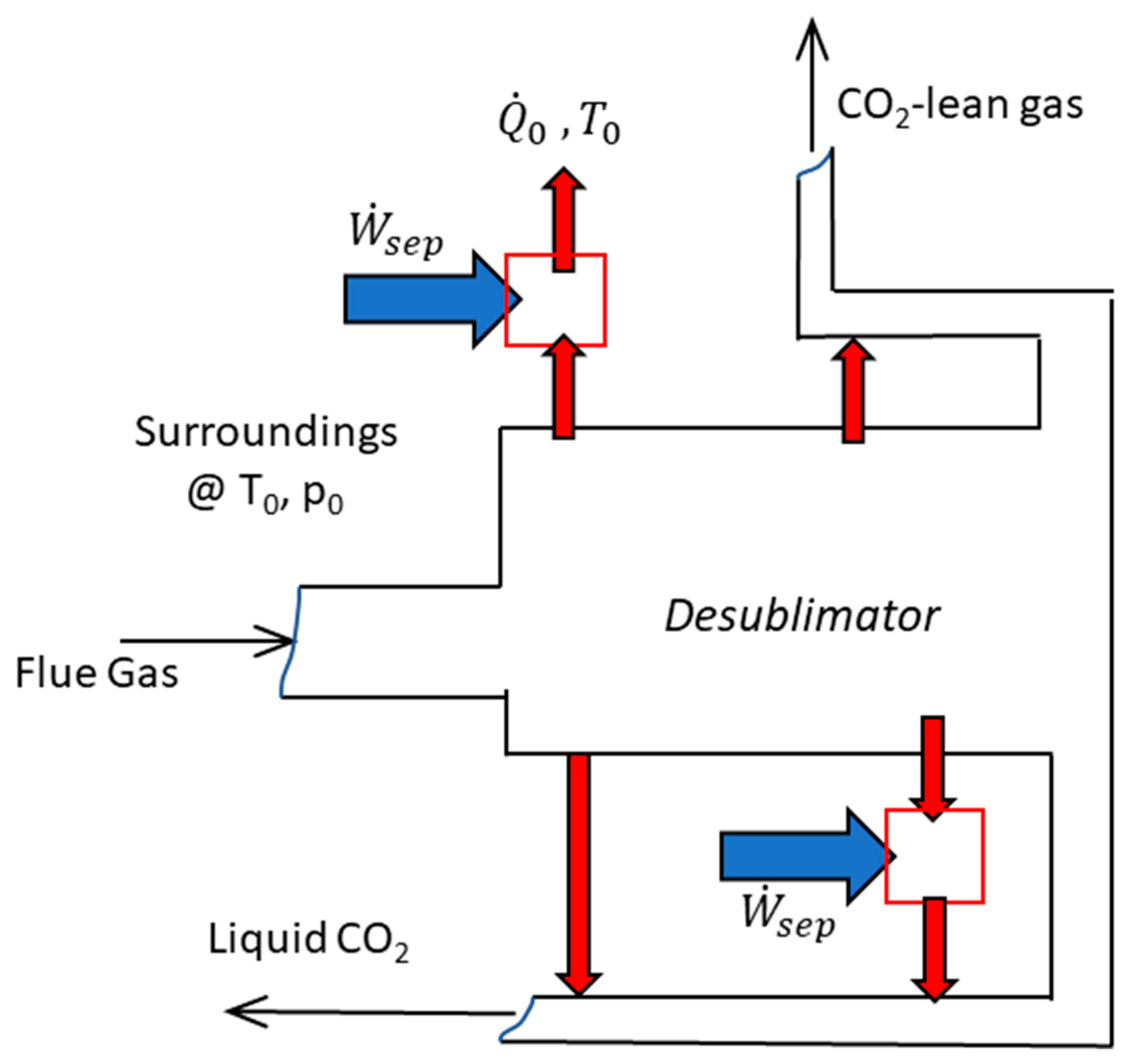
Berger et al. [47]They proposed a conceptual framework to address the work of separation through cryogenic desublimation; they defined the methodologies for energy balances and energy penalty calculation and proposed the comparison to the minimum work of separation.
Cann [48]The frost front velocity experiments in a fixed packed bed allowed the design of a moving packed bed (setting the bed flowrate to match the frost front velocity) to prevent the excessive accumulation of CO2 frost. He reported heat transfer coefficients, pressure drops, and other fundamental correlations to describe experimental data on desublimation in a moving bed.
James [49]He proposed a model that predicted the behavior of a falling sphere heat exchanger in a desublimating column for CO2 capture. Desublimation and condensation of molecules in flue gas streams occurring in a countercurrent falling sphere heat exchanger have been modeled and partially validated with experiments. The model is interesting for spray chambers but is limited by the fact that the majority of the properties used to calculate heat transfer are at film temperature.
Sun et al. [50],
Wu et al. [51],
Wu and Webb [52]
Frost formation and frost release on surfaces, frost growth and densification, and frost release: detailed modeling of experimental results.
Lei et al. [53]CO2 desublimation on a cooled cylinder surface by means of lattice Boltzmann model with 2D simulations, various behaviors in response to different operation conditions.
Table 2. Advantages and challenges of cryogenic CO2 capture processes based on desublimation.
Cryogenic ProcessAdvantagesChallenges
Dynamic packed bed
  • Operating at atmospheric pressure
  • Low-pressure drops
  • Simultaneous removal of H2O and CO2
  • Relying on availability of LNG
  • Heat losses due to CO2 frost accumulation in packed beds
External cooling loop
  • Relatively high TRL
  • Energy storage potential
  • Simultaneous treatment of pollutants
  • High capital cost
  • Need for multiple and/or mixed refrigerants
Stirling cooler
  • Operating at atmospheric pressure
  • Energy storage potential
  • Simultaneous removal of H2O and CO2
  • Heat losses due to CO2 frost accumulation in heat exchangers
  • System oscillations
AnSU
  • Relatively high TRL
  • Operating at atmospheric pressure
  • Recovery of CO2 latent heat of fusion
  • Relying on availability of LNG
  • Heat losses due to CO2 frost accumulation in heat exchangers
NLCCT
  • Low operational cost
  • Water savings potential
  • Simultaneous treatment of pollutants
  • Low heat transfer rates of cold N2 gas
  • No experimental campaign
Table 3. Performance comparison of cryogenic CO2 capture processes based on desublimation.
Cryogenic ProcessFeed CO2 Concentration (mol%)Cold Energy SourceCO2
Recovery (%)
Minimum Specific Energy Consumption (MJe kgCO2−1)Type of StudyReference
Dynamic packed bed10LNG993.60Experimental and ModelingTuinier et al. [56]
External cooling loop16Multiple
refrigerants
900.74Experimental and ModelingJensen et al. [30]
Stirling cooler13Stirling cooler950.55Experimental and ModelingSong et al. [71]
AnSU12LNG901.18ExperimentalPan et al. [54]
NLCCT6.7Cold N2 gas990.63ModelingDe et al. [80]
Disclaimer/Publisher’s Note: The statements, opinions and data contained in all publications are solely those of the individual author(s) and contributor(s) and not of MDPI and/or the editor(s). MDPI and/or the editor(s) disclaim responsibility for any injury to people or property resulting from any ideas, methods, instructions or products referred to in the content.

