Article

Dynamics and Wake Interference Mechanism of Long Flexible Circular Cylinders in Side-by-Side Arrangements

1
State Key Laboratory of Hydraulic Engineering Intelligent Construction and Operation, Tianjin University, Tianjin 300350, China
2
State Key Laboratory of Hydraulics and Mountain River Engineering, Sichuan University, Chengdu 610065, China
*
Authors to whom correspondence should be addressed.
Energies 2024, 17(11), 2741; https://doi.org/10.3390/en17112741
Submission received: 9 May 2024 / Revised: 24 May 2024 / Accepted: 1 June 2024 / Published: 4 June 2024

Abstract

:
The vortex-induced vibrations of two side-by-side flexible cylinders in a uniform flow were studied using a three-dimensional direct numerical simulation at Reynolds number Re = 350 with an aspect ratio of 100, and a center-to-center spacing ratio of 2.5. A mixture of standing-traveling wave pattern was induced in the in-line (IL) vibration, while the cross-flow (CF) vibration displayed a standing-wave characteristic. The ninth vibration mode prominently occurred in both IL and CF directions, along with competition between multiple modes. Proximity effects from the neighboring cylinder caused the primary frequency to be consistent between IL and CF vibrations for each cylinder, deviating from the IL to CF ratio of 2:1 in isolated cylinder conditions. Repulsive mean lift coefficients were observed in both stationary and vibrating conditions for the two cylinders due to asymmetrical vortex shedding in this small gap. Comparatively, lift and drag coefficients were notably increased in the vibrating condition, albeit with a lower vortex shedding frequency. Positive energy transfer was predominantly excited along the span via vortex shedding from the cylinder itself and the neighboring one, leading to increasing lower-mode vibration amplitudes. The flip-flopping (FF) wake pattern was excited in the stationary and vibrating cylinders, causing spanwise vortex dislocations and wake transition over time, with the FF pattern being more regular in the stationary cylinder case.

1. Introduction

In recent years, vortex-induced vibrations (VIV) of multiple circular cylinders have been extensively explored due to their importance in ocean engineering applications such as marine energy harvesting, marine drilling, production risers, heat exchanger tubes bundles, and offshore platforms [1,2]. The configuration of two side-by-side cylinders is considered fundamental among multiple cylinder setups and has gained increasing attention for its vibration responses and flow characteristics [3,4].
For the flow around two side-by-side cylinders, four distinct spacing ratio s/D regions (s is the center-to-center distance, D is the cylinder diameter) can be identified based on different wake patterns [5,6,7]. (1) Small spacing ratio (s/D < 1.1~1.2), no vortices are presented in the gap between the cylinders, forming a single vortex street; (2) middle spacing ratio (1.1~1.2 ≤ s/D < 2.2~2.7), a biased flow is observed in the gap, with a narrow and wide wake alternatively appearing behind one of the cylinders; (3) large spacing ratio (2.2~2.7 ≤ s/D < 4.0~5.0), two parallel vortex streets appear behind the cylinders; (4) further separation (s/D ≥ 4.0~5.0), no significant interaction between the wakes of the two cylinders is excited. Zhou et al. [8] observed that at s/D > 2.5, the interference between the two cylinders weakens, leading to wake flow patterns exhibiting either in-phase (IP) (vortices shed from the lower/upper side of the two cylinders synchronously) or anti-phase (AP) (vortices of the two cylinders both shed from the gap or freestream from the side together) synchronized patterns. Supradeepan and Roy [9] numerically investigated the flow patterns around two side-by-side cylinders at Reynolds number Re = 100 and identified five different flow patterns with the s/D ranging from 1.1 to 8.0, i.e., the single bluff body periodic pattern, aperiodic pattern, anti-phase, in-phase, and the transformation pattern, respectively. Ren et al. [2] numerically analyzed the wake patterns around two side-by-side cylinders at s/D < 3.5 and Re < 400 and found a flip-flopping flow pattern (FF, intermittently and randomly changing the direction of the gap flow) at s/D = 1.6~2.8.
When the two cylinders oscillate freely, the wake features and dynamic responses are obviously dissimilar with those of the stationary cylinders, due to the intricate fluid-structure interaction. Experimental studies by Kim and Alam [10] focused on the vibration characteristics of two elastically supported cylinders in side-by-side arrangements with cross-flow (CF) motion. They identified four vibration patterns: (1) both cylinders reaching maximum vibration amplitudes at the same reduced velocity; (2) no vibration responses for either cylinder; (3) each cylinder reaching its maximum vibration amplitude at different reduced velocities; (4) vibration responses of each cylinder resembling that of a single isolated cylinder. In a numerical study by Chen et al. [11], various wake patterns were observed for two side-by-side cylinders with CF vibration, including the irregular pattern, in-phase FF pattern, out-of-phase FF pattern, IP synchronized pattern, AP synchronized pattern, and the biased AP synchronized pattern. Munir et al. [12] numerically investigated the VIV of two elastically mounted and rigidly coupled side-by-side circular cylinders and noted a weak interference between the cylinders at s/D = 4, as well as the same lock-in region as that of an isolated cylinder. Xu et al. [13] simulated the VIV of two elastically mounted side-by-side cylinders at s/D = 4, 6, and 10, where the vibration amplitudes of both cylinders followed similar trends with increasing reduced velocity, dropping to smaller values earlier when compared to the isolated cylinder. Vortex shedding of two flexible cylinders is a complex phenomenon influenced by various factors such as aspect ratio, end-effects, and structural vibrations. Studies by Ramberg [14] and Silva-Leon and Cioncolini [15] have explored the impact of boundary conditions on cylinder vortex shedding, highlighting a significant correlation with cylinder end-conditions shaping three-dimensional flow features in the wake. Interestingly, except for free-end effects, the vortex shedding frequency remains consistent, suggesting that bent cylinders are less affected by end-conditions.
Multi-mode vibrations and more intricate interactions can occur in two flexible side-by-side cylinders as a result of the evolution of the spacing between the cylinders during the oscillation. Increasing investigations have focused on flexible conditions due to their similarities with the VIV of slender flexible risers in engineering applications. Zhou et al. [16] performed wind tunnel experiments on the VIV of side-by-side flexible cylinders in a cross flow, identifying three wake patterns for different spacing ratios (s/D = 3, 1.7, 1.13). Following this, So and Wang [17] further numerically studied the wake patterns of two flexible cylinders with the same s/D as Zhou et al. [16] at Re = 800 using the strip methodology, observing in-phase and anti-phase wake patterns with varied vibration responses. Huera-Huarte and Gharib [3] experimentally explored the vibration responses of two side-by-side flexible cylinders, identifying VIV and wake-coupled VIV cases with weaker and stronger interactions between two cylinders at s/D = 3.5 and s/D < 3.5, respectively. Han et al. [18] experimentally examined the hydrodynamic forces on two side-by-side flexible cylinders at s/D = 3, 4, 6, 8, revealing increased force coefficients during mode resonances. However, the CF and IL force frequencies of the two cylinders are slightly different from each other when s/D < 6. Xu et al. [19] conducted experiments on the VIV of two side-by-side flexible cylinders at s/D = 3, 4, 6, 8, and found that the maximum primary modes were fourth and sixth in CF and IL directions for both two cylinders, respectively. Higher-order mode vibrations were found to be easily excited in side-by-side configurations compared to single flexible cylinders. Liu et al. [4] experimentally analyzed the VIV of three side-by-side cylinders at s/D = 3.5, 4, 5, 6, 8, and found substantial mode competition between the cylinders, due to strong proximity disturbance and wake interference.
The existing studies on side-by-side cylinders mainly focused on the variation of amplitude and frequency of flexible cylinders with space ratios. However, the underlying mechanism of interactions between the multi-mode vibration and three-dimensional (3-D) vortex shedding remains unclear, especially in the proximity of two cylinders. A reason for that can be attributed to the fact that most of the previous studies were carried out experimentally, and the details of the hydrodynamic force and 3-D wake patterns are very difficult to acquire. Therefore, in the present paper, the VIV of two side-by-side flexible cylinders with aspect ratio L/D = 100, Re = 350, and s/D = 2.5 was investigated via 3-D direct numerical simulations, to further elucidate the dynamic interference of vortex shedding, mode competition, and wake transition between the cylinders. The results of the literature research showed that this was the initial attempt to numerically investigate the VIV of two side-by-side slender flexible circular cylinders using 3-D simulations. The fluid forces and wake structures for two stationary side-by-side cylinders were preliminarily investigated for comparison in Section 3. The vibration responses, mode transition, energy transfer, and wake interference mechanism of two side-by-side flexible cylinders are elucidated in Section 4. Finally, the main conclusions are shown in Section 5.

2. Numerical Model and Validation

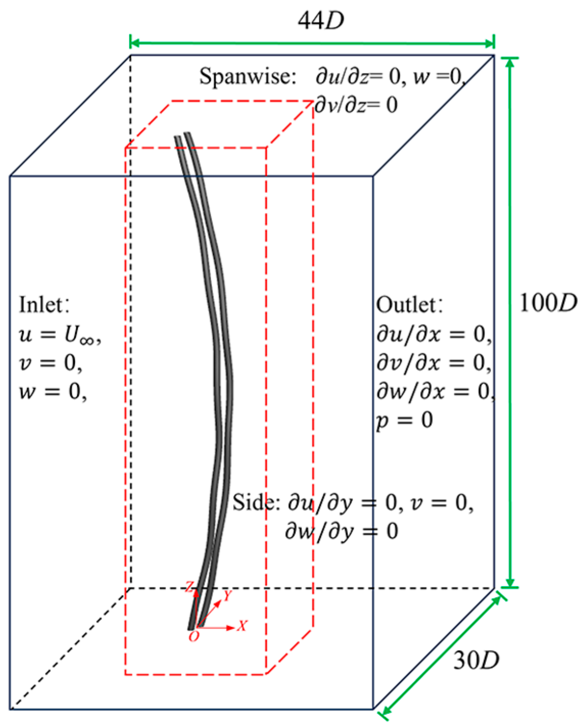
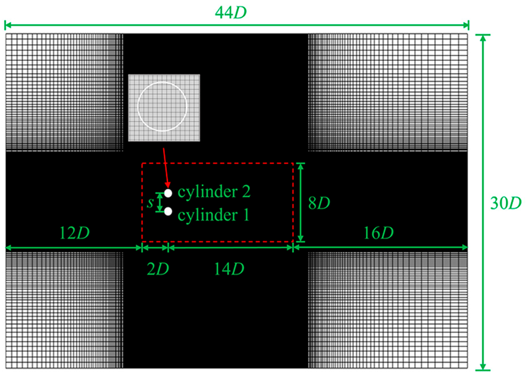
2.1. Numerical Methods

The 3-D incompressible Navier–Stokes equations governing the fluid flow were solved utilizing the iterative immersed boundary (IB) method [20]. The conservative forms regarding the temporally-discretized second-order Adams–Bashforth equations for incompressible flow are given by the equations below:
u n + 1 = u n + δ t 3 2 h n + 1 2 h n 1 3 2 p n + 1 2 p n 1 + f n + 1 2 δ t
u n + 1 = 0
where u represents the velocity, p stands for the pressure, and h = ∇∙(−uu + ν(∇u + ∇ut)) includes convective and diffusive terms. Here, ∇ denotes the gradient operator and the superscript t is the matrix transposition. Superscripts n + 1, n + 1/2, n, and n − 1 refer to the time stepping. The extra body force f at time step of n + 1/2 is calculated as:
f n + 1 2 δ t = D F n + 1 2 δ t = D V n + 1 I δ t 3 2 h n + 1 2 h n 1 3 2 p n + 1 2 p n 1
where F represents the extra body force and V is the desired velocity on IB points. D(Φ,x) and I(ϕ, Xi) are the distribution and interpolation functions mentioned in Peskin [21].
The predictor-corrector procedure (two-step) was adopted to decouple the governing equations (Equations (1)–(3)). The resultant pressure Poisson equation was solved using the biconjugate gradient stabilized method [22], preconditioned by the geometric multi-grid method. Refer to our previous work [20] for further details.

2.2. Fluid-Structure Interaction Model

As seen in Figure 1, the domain has the in-line (x), cross-flow (y), and spanwise (z) lengths of 44D, 30D, and 100D, respectively. The circular cylinders were positioned in 14D from the inlet and 30D to the outlet. These cylinders were aligned parallel on the side walls, with a circular cross-section having an aspect ratio L/D of 100 (where L is the length and D is the diameter of the cylinder). The initial spacing ratio between cylinder 1 (Cyl-1) and cylinder 2 (Cyl-2) was set at s/D = 2.5, to explore the strong interferences in wake structures and vibration dynamics between these two cylinders [7]. Re = 350 was chosen for this study because it fell within the subcritical flow range of 300 < Re < 1.4 × 10⁵, allowing for the attainment of a turbulent state. The hydrodynamic characteristics observed at low Re are akin to those seen at high Re, as noted in previous studies [23,24]. This selection has practical implications for engineering based on the efficiency and cost-effectiveness of Re = 350 in comparison to the resource-intensive three-dimensional direct simulations.
The boundary conditions depicted in Figure 1 included Dirichlet conditions at the inlet, Neumann conditions at the outlet, free-slip conditions at the side boundaries and spanwise boundaries, and nonslip conditions on the cylinder surface.
The cylinders were modeled as tension-dominated cables with pinned-pinned ends, freely oscillating in both the CF and IL directions. The rationale for selecting pinned-pinned boundary conditions was as follows. The cylindrical boundary conditions and aspect ratio play a crucial role in determining vibration mode and wake pattern. Gao et al. [25] conducted simulations on a flexible cylinder under various boundary conditions, revealing distinctive vibration displacements based on the aspect ratio. The study found that differences in vibration displacement diminished as the aspect ratio increased significantly. Previous research primarily focused on flexible cylinders with pinned-pinned ends due to their relevance to production pipelines and risers. However, the VIV characteristics of tensioned cable models with pinned-pinned ends warrant further investigation to enhance understanding in this area. The governing equation for the structural dynamics is:
m A ¨ x , y ( z ) T A x , y ' ' ( z ) + K A ˙ x , y ( z ) = C d , l ( z ) 2
where ‘•’ and ‘'’ denote the time and space derivatives. The mass ratio m = (ρcL)/(πρfD2L/4) = 6 is defined as the ratio between the cylinder’s structural mass to its displaced fluid mass, where ρc is the mass per unit length. The tension and damping of the structure are represented by τ and η, nondimensionalized as T = τ/ρfD2  U 2 and K = η/ρfD U 2 , respectively. In this study, the tension T was specified as 496.0, corresponding to a reduced velocity Ur = 2LD m / T = 22.0 [26], and the structural damping K was set to zero to induce significant amplitude oscillations. The CF and IL structural displacements, normalized by D, are denoted as Ax(z) and Ay(z), respectively. The dimensionless CF and IL sectional force coefficients are defined as Cl(z) = Fy(z)/(1/2ρfD U 2 ) and Cd(z) = Fx(z)/(1/2ρfD U 2 ), where Fy(z) and Fx(z) are the dimensional sectional fluid forces along the CF and IL directions, respectively.
As shown in Figure 2, the computational domain was discretized using a Cartesian mesh. In the x-y plane, a uniform mesh in grid spacing Δx = Δy = D/32 was implemented around the cylinders within (x × y) = (16D × 8D) (red dash rectangle in Figure 2) to ensure adequate IB points on the cylinder surface and to accurately capture flow pattern. Beyond this region, the mesh was then stretched out. Along the z direction, a uniform mesh with a grid spacing (Δz ≈ 0.13D) was used to guarantee the stability of three-dimensional flow [27]. The mesh convergence of this density has been thoroughly verified in our previous research on VIV of a flexible cylinder at L/D = 50, Ur = 5.0, and 15.0 with Re = 500 [28], confirming the accuracy of the mesh. Consequently, the grid resolution was established as 640 × 384 × 768 in the x, y, and z directions. The dimensionless time step (∆tU/D) was set at 0.001 to meet the CFL criteria (Ut/∆x < 0.5). In the present study, every simulation was carried out for a dimensionless timespan of t* = Nstep × ∆t × U/D = 600 to ensure complete vortex shedding development. The statistical analysis period was 300 nondimensional time units after achieving flow stability, meeting the dynamic analysis criteria. Additionally, each scenario necessitated approximately 450 h with 64 CPU cores on a high-performance computing cluster.
The numerical models utilized in the present research have been successfully applied in various studies. Further details on the validation can be found in Appendix A.

3. Flow around Two Side-by-Side Stationary Cylinders

The flow around two stationary cylinders in side-by-side conditions is preliminarily discussed in this section. This illustrates the key characteristics of the wake flow and the fluid forces in the stationary cylinders before further investigating the dynamic responses of two flexible cylinders in the same configurations.
Figure 3 shows the spatial-temporal hydrodynamic forces for Cyl-1 and Cyl-2. For the same spanwise location, the force coefficients alternatively changed with time, showing the periodic vortex shedding from the two cylinders. At the same time, the lift coefficients showed significant spanwise variations, which can be related to the differences in the vortex strengths along the span. Both force coefficients (lift and drag) of the two cylinders are displayed in oblique and discontinuous stripes in the temporal-spanwise domain, suggesting vortex shedding in a phase-lag feature at different spanwise locations. Note that the drag coefficients shown in Figure 3a,c indicate the drag fluctuations with the mean drag coefficients being deducted. However, the drag coefficients for Cyl-1 and Cyl-2 showed opposite distributions in the spatial-temporal domain, e.g., when the drag coefficient of Cyl-1 was positive, Cyl-2 showed a negative value, as illustrated by the black rectangles in Figure 3a,c. This finding suggests a compelling waxing and waning relationship between the drag coefficients of Cyl-1 and Cyl-2, suggesting the existence of the flip-flopping pattern. As stated by Chen et al. [11,29] and Yan et al. [30], the flow field pattern is characterized by the deflected gap flow and the resulting narrow-wide wake structure, known as the FF pattern. The cylinder with the narrower wake experiences higher drag, whereas the cylinder with the wider wake encounters lower drag. However, in low-Re flows, the narrow-wide wake pattern undergoes a reversal after multiple vortex-shedding cycles due to the intermittent and irregular shifts of the biased gap flow.
Figure 4 shows the changes in the time-averaged mean and root mean square (RMS) values of drag and lift coefficients across the span. Owing to the spanwise variability in the strength and phase of vortex shedding, each cylinder exhibited distinct fluctuations in the mean and RMS force coefficients in the spanwise direction. Notedly, mean lift coefficients had opposite signs for the two cylinders, indicating a repulsive force between them, which arose from asymmetrical vortex shedding for each cylinder in s/D = 2.5 condition. Specifically, the gap flow velocity was lower than that of the freestream sides of the two cylinders in a side-by-side arrangement, creating a pressure differential between the gap-side and freestream side of the cylinders. As a result, repulsive forces towards the freestream side of Cyl-1 and Cyl-2 were generated, respectively.
To further explain the mechanisms behind the fluctuating force coefficients depicted in Figure 3 and Figure 4, Figure 5 illustrates the flow patterns around the adjacent stationary cylinders. Figure 5a,b display the instantaneous iso-surfaces of three-dimensional vortex structures (color-coded by spanwise vorticity, ωz) at a nondimensional time t* = 350; Figure 5c–f depict the two-dimensional vortex shedding outlines at z/D = 20, 30, 47, and 70. Alternating spanwise vortex tubes can be observed in the wake trailing the cylinders, running roughly parallel to the cylinder axis. However, in specific spanwise locations, slight bending was noticeable along the vortex tubes in the immediate wake region (highlighted by the green dashed rectangle in Figure 5a). Vortex dislocations emerged near the interfaces between locally curved vortex tubes, such as around z/D = 35. Additionally, the transient vortex shedding patterns, as shown in Figure 5c–f, exhibited variations with respect to spanwise position, reflecting the characteristics of vortex dislocations. For example, an anti-phase (AP) vortex-shedding pattern emerged at z/D = 20 (Figure 5c), while an in-phase (IP) pattern was observed at other locations (Figure 5d–f). The dynamic mode decomposition (DMD) of wake flows presented by Yan et al. [30] demonstrates that the FF flow fundamentally originated from the interactions between AP and IP instabilities. In the AP pattern, vortices were on the verge of shedding from the freestream sides of both cylinders, resulting in a parallel gap flow in the immediate wake with nearly equal wake widths. It should be noted that the intensity of the freestream side vortices surpassed that of the gap-side vortices, owing to the inhibition from the adjacent cylinder in this narrow gap, which consequently gave rise to a repulsive lift on both cylinders, as depicted in Figure 4b.
In the IP pattern, vortices on the upper or lower sides of both cylinders developed simultaneously, as illustrated in Figure 5d–f. The gap flow either deflected upwards (Figure 5d,f) or downwards (Figure 5e), resulting in patterns of narrow-wide wakes. Additionally, the timing and spatial pattern of vortex shedding varied across different spanwise positions. For instance, the vortex rolling and shedding in the wider wake at z/D = 47 (Figure 5e) exhibited a greater upward angle compared to that in the narrower wake at z/D = 70 (Figure 5f) (indicated by the green dashed circle).
Variations in the lift and drag coefficients over time at a specific spanwise location of the cylinders in Figure 3 are linked to different vortex shedding patterns. To illustrate the evolution of the vortex shedding, instantaneous 2-D contours of the spanwise vorticity in the (x, y) plane at mid-span at various time intervals are presented in Figure 6a–d. Each cylinder exhibited a ‘2S’ vortex shedding pattern (two single vortices shed per cycle) [31]. It is important to note that although both cylinders showed vortex shedding in a ‘2S’ pattern, the intensity of the vortices differed on the gap-side and freestream side. Moreover, a noticeable wake transition from AP (Figure 6a,b) to IP (Figure 6c,d) was observed. In the AP wake, as shown in Figure 6a,b, due to the weaker intensity on the gap side, the vortices dissipated faster than on the freestream side. A similar weakening of the gap-side shear layers was also observed in the IP pattern (Figure 6c,d). However, as depicted in Figure 6e, the discrepancy in drag coefficients in the AP pattern (Figure 6a,b) was larger than in the IP pattern (Figure 6c,d), which can be attributed to the differences in shape between the two wake patterns. This phenomenon is highlighted in the study of flow around two-dimensional side-by-side cylinders by Zhou et al. [32].

4. Vortex-Induced Vibration of Two Side-by-Side Flexible Cylinders

Increasingly intricate responses and wake patterns were excited during the flexible cylinder oscillations as compared to the stationary conditions. The objective of this section was to analyze the vibration responses, fluid forces, and vortex features of side-by-side cylinders. The underlying mechanisms for mode competition and vortex interferences for the two flexible cylinders are further explained.

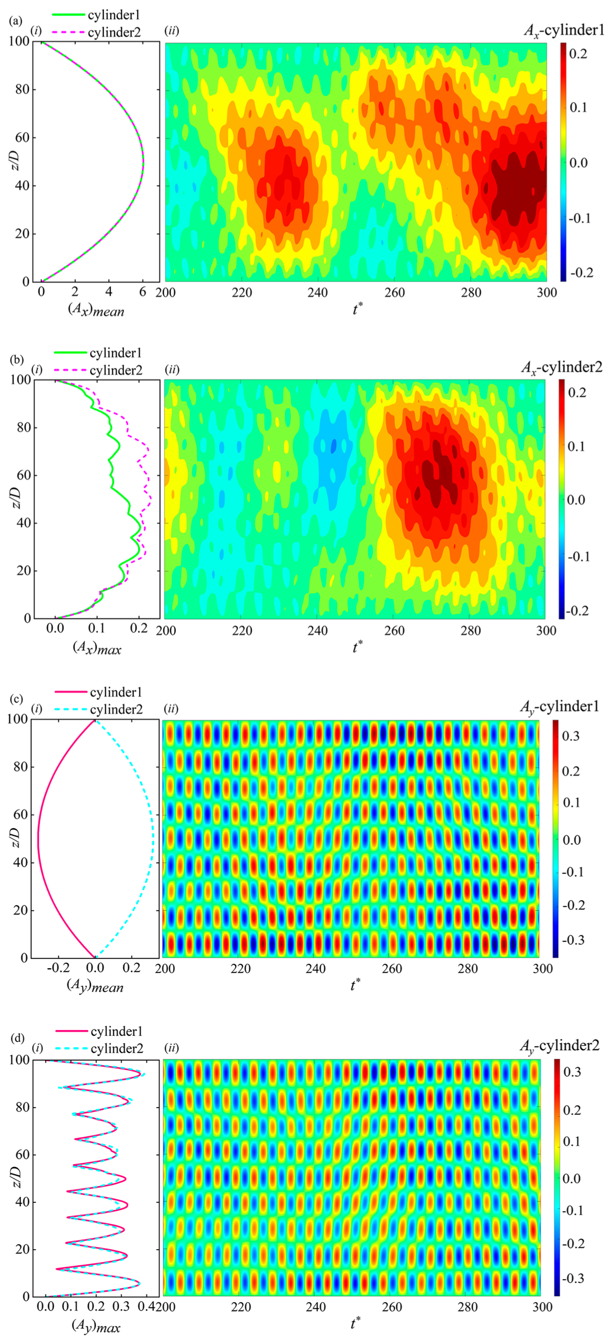
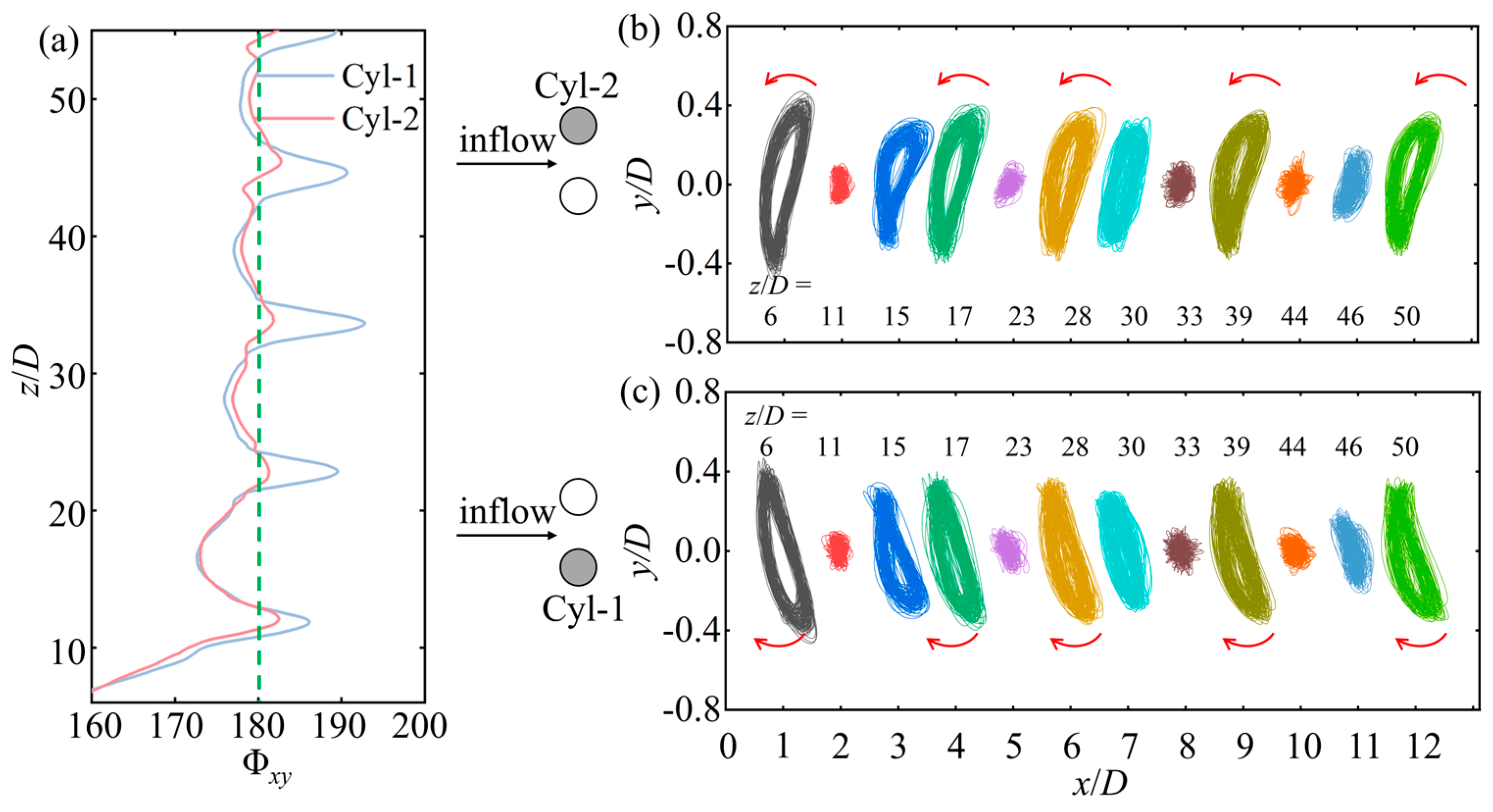
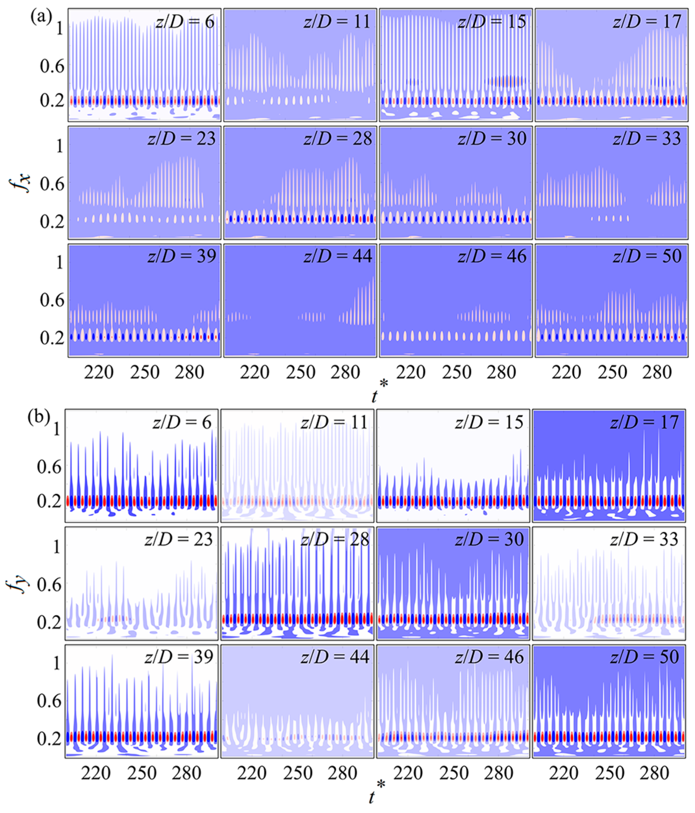
4.1. Vibration Response

Figure 7 illustrates the mean and maximum values of dimensionless IL ((Ax)mean, (Ax)max) and CF ((Ay)mean, (Ay)max) displacement along the span, as well as the spatial-temporal distributions of instantaneous IL and CF displacements. The instantaneous displacement Ax and Ay, along with their maximum values (Ax)max and (Ay)max, have the time-averaged values subtracted at each spanwise location. In Figure 7a(i),c(i), the cylinder showed downstream deflection from the initial position in the IL direction, while in the CF direction, it deflected towards the freestream side. The maximum mean values of IL and CF displacements of the two cylinders were symmetrical about the mid-span, approximately 6.1% of the cylinder’s length in the IL direction. The mean IL displacement value for Cyl-1 closely matched that of Cyl-2, while the CF mean amplitudes were significantly smaller than those in the IL direction. Additionally, the magnitude of CF mean displacement for the two cylinders was equal but with opposite values, attributed to the repulsive forces between them.
In Figure 7b(i), the maximum value of IL displacement showed asymmetrical distributions, and the spanwise fluctuation of the two cylinders varied considerably. Significant differences were also evident in the mismatches on the anti-nodes and nodes of the response profiles for the two cylinders. Although the ninth mode was predominant in Figure 7b(i), a strong combination of other modes was indicated by the nonzero nodes of the profiles. This traveling characteristic is also observed in Figure 7a(ii),b(ii), where no clear separation was seen between the vibration cells in the spatial-temporal domain, presenting a powerful mixture of standing-traveling waves. Furthermore, higher IL vibration fluctuations accumulated near the mid-span region as the traveling wave propagated back and forth from the two ends to the midspan, as depicted in Figure 7a,b.
In the CF direction (Figure 7d(i)), the vibration profiles of the two cylinders exhibited similar shapes and magnitudes, with the ninth mode being predominant. Multiple vibration cells were distinguished along the span, with nodes showing minimum values and anti-nodes demonstrating maximum values, indicating a distinct standing-wave pattern. Despite nonzero displacements at the nodes, it suggested the influence of traveling-wave components on the standing-wave patterns, while the radial vibration remained dominant. A comparison of the IL and CF vibrations revealed that IL vibration was more affected by the proximity of the neighboring cylinder compared to CF vibration, highlighting significant differences between the two cylinders. This observation aligned with the findings of Xu et al. [19] regarding flow-induced vibrations of closely positioned cylinders, where interactions led to increased IL displacements.
The power spectral densities (PSD) of the in-line (IL) and cross-flow (CF) displacements are illustrated in Figure 8. Despite the different distributions of temporal-spatial vibrations in the IL and CF directions for the two cylinders, the primary frequencies of their vibrations were consistent, displaying minimal variances in low-frequency components. Hence, for conciseness, only the PSD of Cyl-1’s displacements is shown. In Figure 8, a main frequency of 0.202 was detected in both IL and CF motions, corresponding to the ninth vibration mode. In the IL direction, various frequency components were present, with a lower frequency of 0.049 and a higher frequency of 0.404 (indicated by black dashed lines). The lower frequency components clustered around 0.049, indicating broadband characteristics, while the higher frequency components had much lower intensities. In CF motion, the predominant frequency of 0.202 with significantly higher intensity related to the ninth mode was observed across the entire span, consistent with the standing-wave response in the CF direction. Additionally, a vibration frequency ratio of 1 was established between the dominant IL and CF frequencies for each cylinder, which can be attributed to wake interference caused by the proximity of the neighboring cylinder. This differed from the IL to CF ratio of 2 in a single flexible cylinder scenario [33,34]. A ratio of 1 was also evident in the vortex-induced vibration (VIV) of the near-wall flexible cylinder [28] as well as in two adjacent conditions in a confined space [29]. In the near-wall scenario, suppression of the near-wall side vortex led to a decrease in the IL frequency. A similar mechanism of mutual inhibition between the two cylinders resulted in identical dominant IL and CF frequencies.
To further investigate the synchronization between the IL and CF vibrations of the two cylinders, the time-averaged phase difference between the IL and CF displacements and motion trajectories is depicted in Figure 9. The phase difference of the response displacement is defined as Φxy = [Φx–Φy, mod 360°] [33]. The instantaneous phases of the IL and CF responses (Φx and Φy, respectively) were calculated using the Hilbert transform. As proposed by Dahl et al. [35], in the case of an isolated cylinder undergoing VIV, the phase difference between IL and CF vibrations dictated the shape and orientation of the cylinder’s “Figure 8” trajectories in the span-wise plane. When the values of Φxy fell within the range of 0° to 180° (180° to 360°), they corresponded to ‘counter-clockwise’ (clockwise) orbits wherein the cylinder moved upstream (downstream) upon reaching the CF oscillation peaks. The counter-clockwise orbited (Φxy = 0°–180°) experience stronger shear flow resulting in larger vibration amplitudes and intensified vortex shedding [33,35]. However, under the side-by-side arrangements, each cylinder’s trajectory formed an ‘oval’ shape due to the dominant IL and CF vibration having a frequency ratio of 1. This presented a deviation from the “Figure 8” orbits observed in the scenario of an isolated flexible cylinder with a frequency ratio of 2 [36,37]. In the side-by-side configuration, the phase difference between IL and CF displacements is characterized as Φxy = 0°–180° when each cylinder moved upstream near the outmost CF positions (freestream side), considering the freestream shear layers’ more pronounced impact on the cylinders’ dynamics compared to the gap-side regions.
As presented in Figure 9a, the phase difference alternatively jumped across 180° near the nodes of the CF vibrations along the entire cylinder span. For example, in Figure 9b,c, at the location of anti-nodes (z/D = 6, 17, 28, 39, and 50), the ‘oval’ trajectories, upstream skewed at the outmost CF positions, were observed for both Cyl-1 and Cyl-2, with the IL and CF phase difference at Φxy < 180°. These orbits were favorable for exciting large amplitude vibrations. However, the trajectories at the vibration nodes (z/D = 11, 23, 33, and 44) were disorganized due to the modulation of the irregular frequency components from small vibration amplitudes in both directions, and the values of Φxy were larger than 180° at these positions. Furthermore, vibration trajectories of the cylinders in each period did not perfectly coincide, which is attributed to the disturbance of traveling-wave vibration modes in the IL direction, as also indicated in the spatial-temporal displacement diagram (Figure 7a(ii),b(ii)).

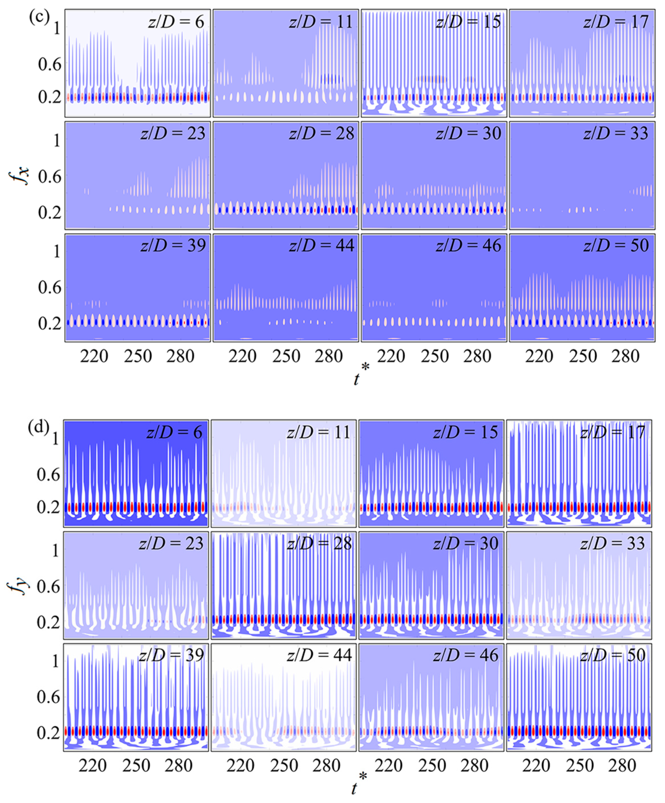
4.2. Mode Competition and Transition

In Section 4.1, despite the primary ninth modes being determined based on the maximum displacement envelopes and PSD, the momentary vibration process remains unclear owing to the excitation of multiple modes, especially when multiple modes associated with different wavenumbers vibrate simultaneously. To elucidate the underlying mechanism for this dynamic behavior, instantaneous mode decomposition was utilized to analyze IL and CF oscillations for two cylinders, as depicted in Figure 10.
Within Figure 10, the ninth mode continued to govern the CF and IL vibration processes, consistent with observations from spatial-temporal displacements (Figure 7c(ii),d(ii)), where the highest amplitude in both CF and IL directions indicated ninth vibrations. In Figure 10b,d,f,h, the second, third, seventh, and eleventh modes in the IL direction were more pronounced with relatively close weights, leading to increased mode competition among them and thus enhancing the traveling-wave characteristic (Figure 7a(ii),b(ii)). For IL vibration, the sum percentage of the 10th to 15th vibration modes of the two cylinders (25.5% for Cyl-1 and 26.7% for Cyl-2) was lower than their respective dominant vibration modes, i.e., the ninth modes. In the case of CF vibration, similar mode interactions were also observed where the combined percentage of the 10th to 15th modes was 28.5% for Cyl-1 and 29.56% for Cyl-2, respectively. It is important to highlight the competition among all potentially engaged modes, with a few modes exhibiting higher influence and predominantly influencing the vibration characteristics. However, except for the dominant mode, the involvement time of other modes differed in the two cylinders. For example, there was a discrepancy in the occurrence timing of the 11th CF mode between the two cylinders (Figure 10a,e), where the 11th mode participated almost entirely in the vibration of Cyl-1, but was not evident for Cyl-2 in the time range of t* = 210~240 (Figure 10c,g). The evolving modal differences between the two cylinders led to the emergence of phase lag in the cylinder motion over time; the distinct behaviors of different modes in each cylinder highlighted the complexity of the system and the dynamic interactions between the two cylinders.
The intermittent engagement of various vibration modes is noticeable in Figure 10, particularly in the IL direction. These distinct vibration modes may arise from the concurrent involvement of these modes and their nonlinear interactions at various spanwise positions. To understand the impact of different oscillation modes along the span and the nonlinear interactions between cylinders throughout the span, the instantaneous frequencies of displacements at specific locations are depicted in Figure 11, using wavelet transform.
As shown in Figure 11a, for the IL vibration of Cyl-1, the dominant frequency at the anti-nodes (z/D = 6, 17, 28, 39, 50) remained consistently at 0.202 across the vibrating process, whereas the frequency of 0.202 at nodes (z/D = 11, 23, 33, 44) appeared intermittently with time. Similar behaviors were also observed at other positions (z/D = 15, 30, and 46). This difference along the span led to the emergence of vibration traveling-waves, contributing to the asymmetrical response profile (Figure 7a(ii),b(ii)) along the span. The frequencies other than 0.202 changed irregularly over time regardless of the spanwise position, leading to irregular modulations of the vibration traveling-wave. In Figure 11c, the IL frequency wavelet transform for Cyl-2 differed from that of cylinder Cyl-1. For example, at z/D = 30, the dominant frequency of 0.202 was present in both Cyl-1 and Cyl-2. However, the higher frequencies around 0.404 manifested at distinct times and magnitudes in each cylinder, leading to noticeable discrepancies in the traveling-wave patterns in the IL spatial-temporal plots (Figure 7a(ii),b(ii)). The distribution of the dominant frequency near 0.202 was also different in both cylinders at z/D = 44, with the absence of this frequency in Cyl-1 but an intermittent occurrence of this frequency in Cyl-2. In addition, the bandwidth was significantly larger, showing the involvement of other higher order frequencies.
As shown in Figure 11b, for the CF vibration of Cyl-1, although there was some superposition of frequencies showing broadband features, the dominant vibration frequency of 0.202 was obvious at the anti-nodes, and the frequency of the CF node position was also prominent, consistent with the above vibration PSD analysis (Figure 8). However, the relative weight of the dominant frequency 0.202 varied in different spanwise locations or even the same spanwise positions of the two cylinders. For instance, at z/D = 23, the frequency of 0.202 was notable between t* = 220 to 250 for Cyl-1, whereas for Cyl-2, it was between t* = 250 to 330. This discrepancy in frequency distribution throughout time contributed to differences in temporal-spatial dynamics between these two cylinders (Figure 7c(ii),d(ii)).

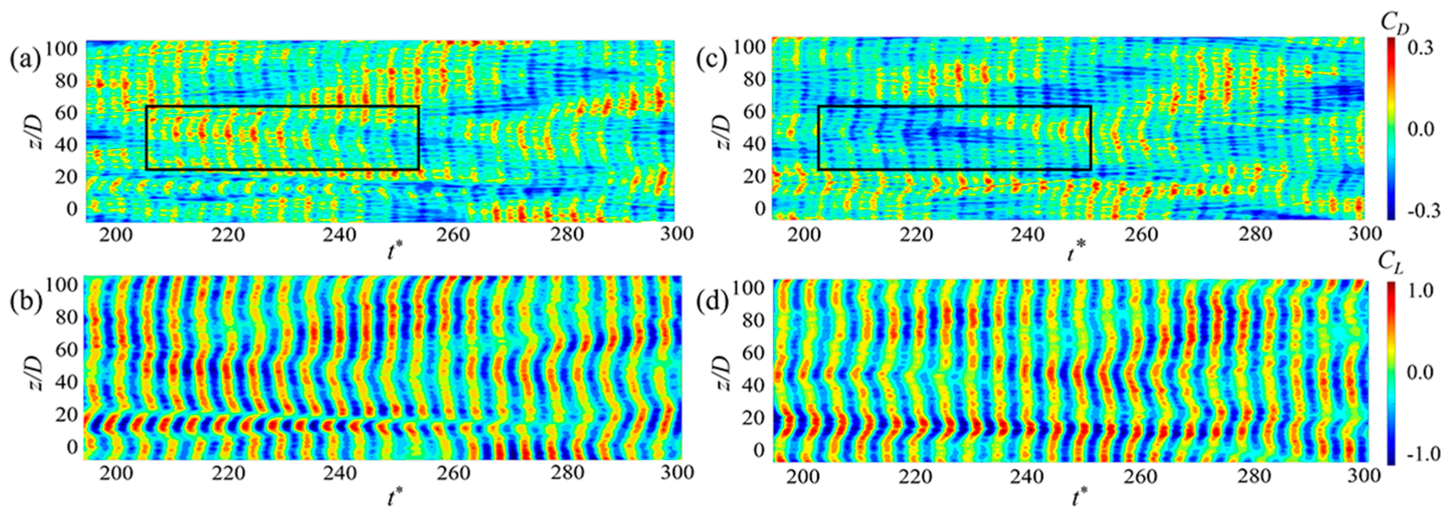
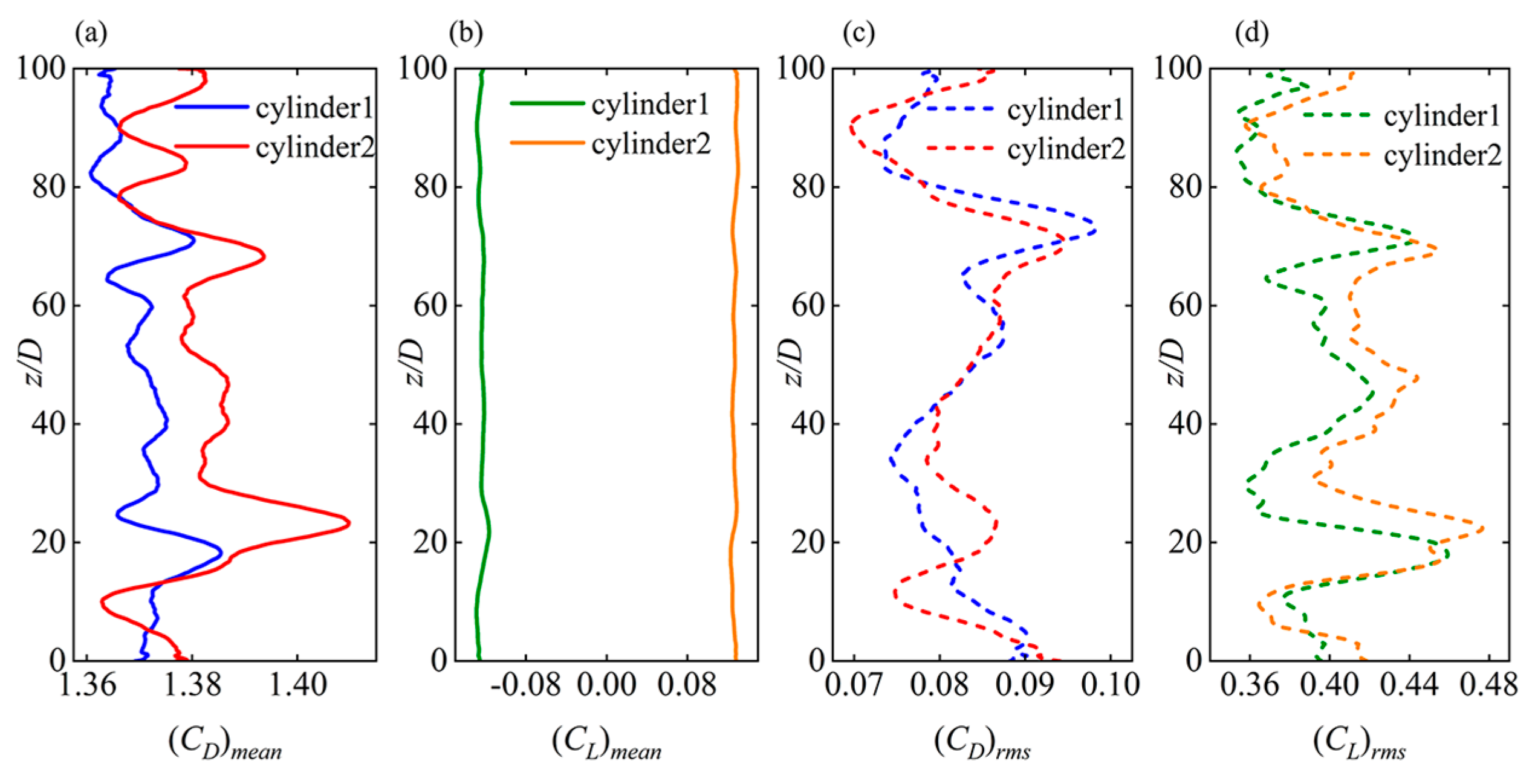
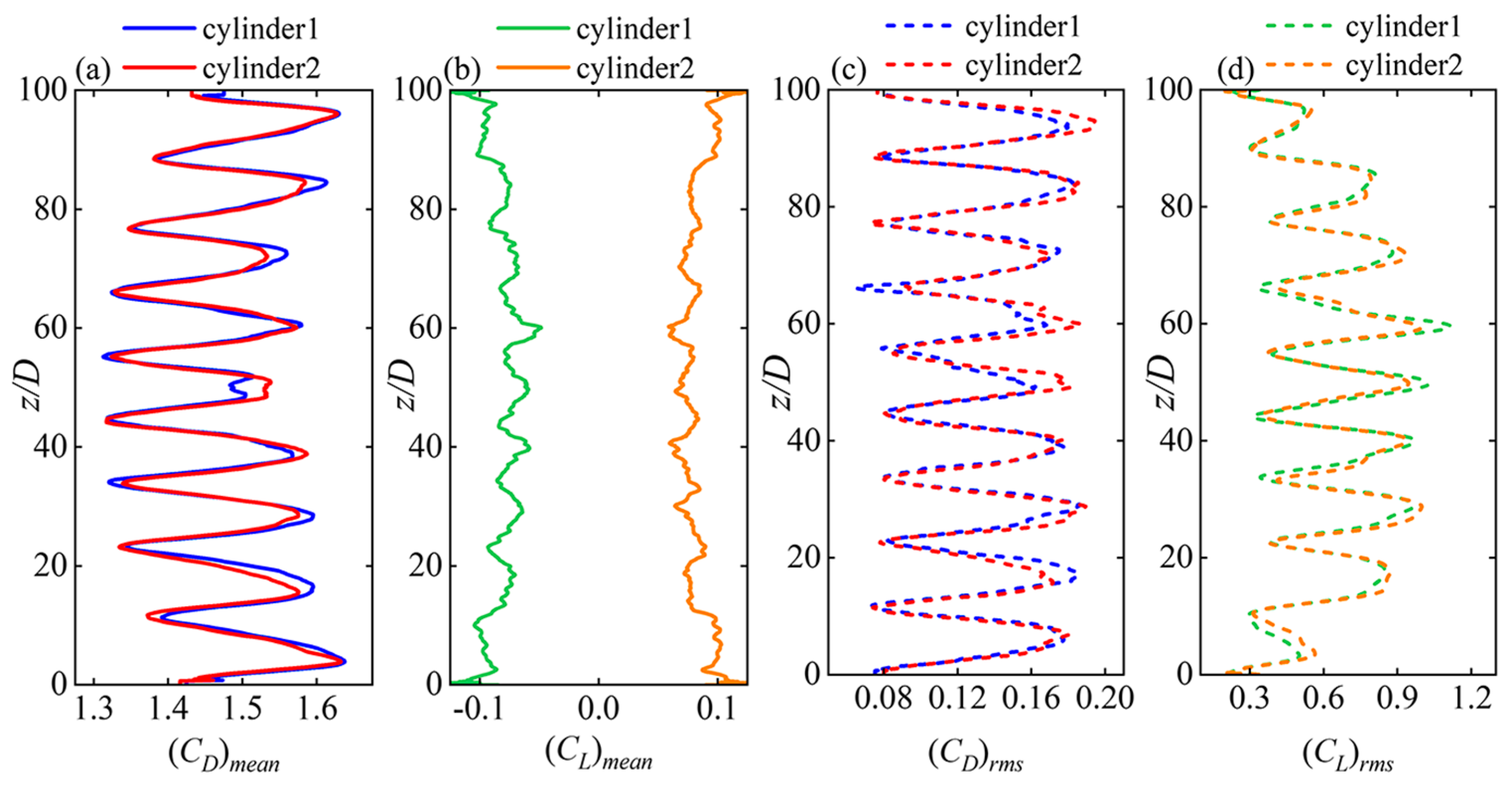
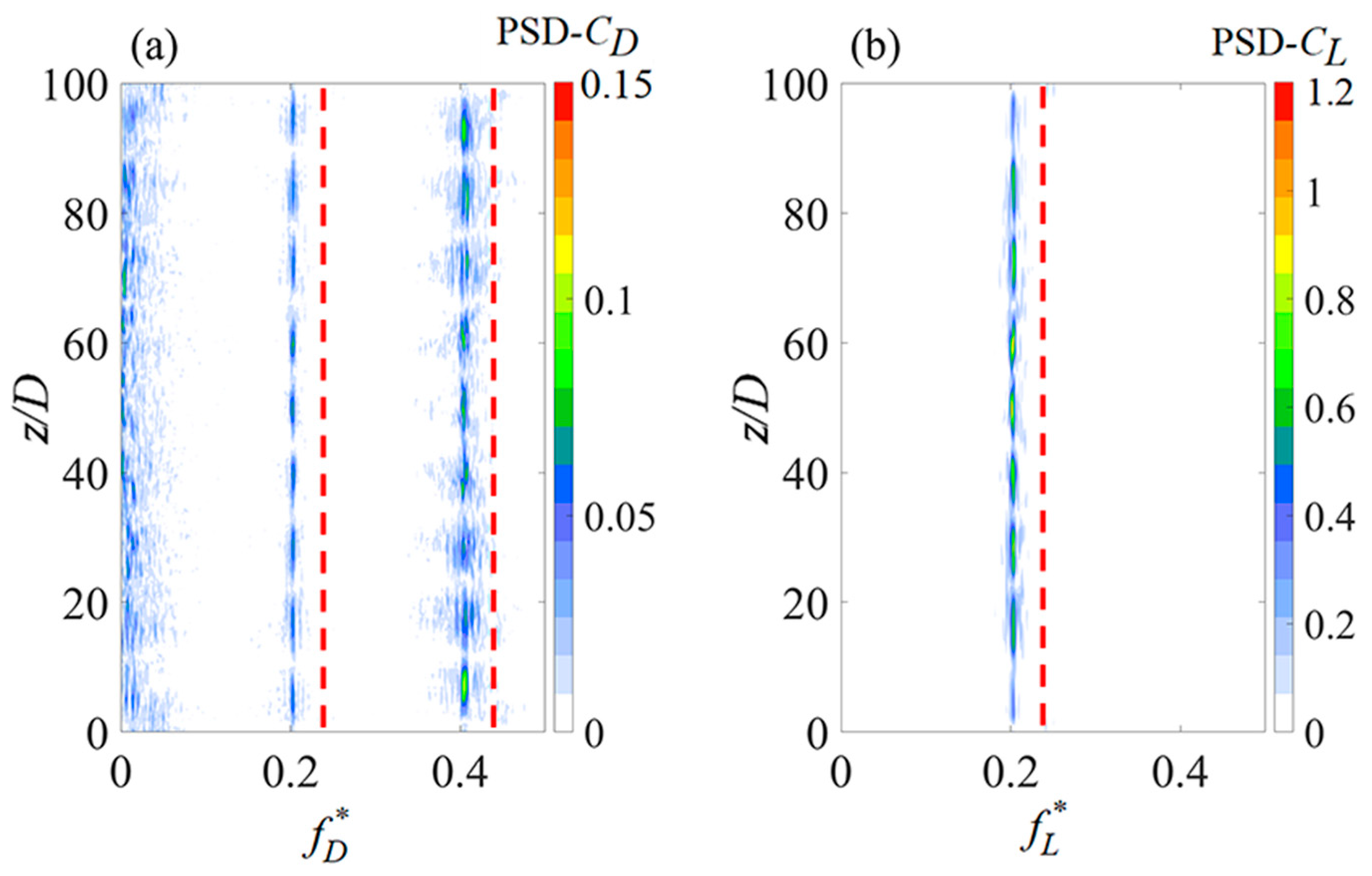
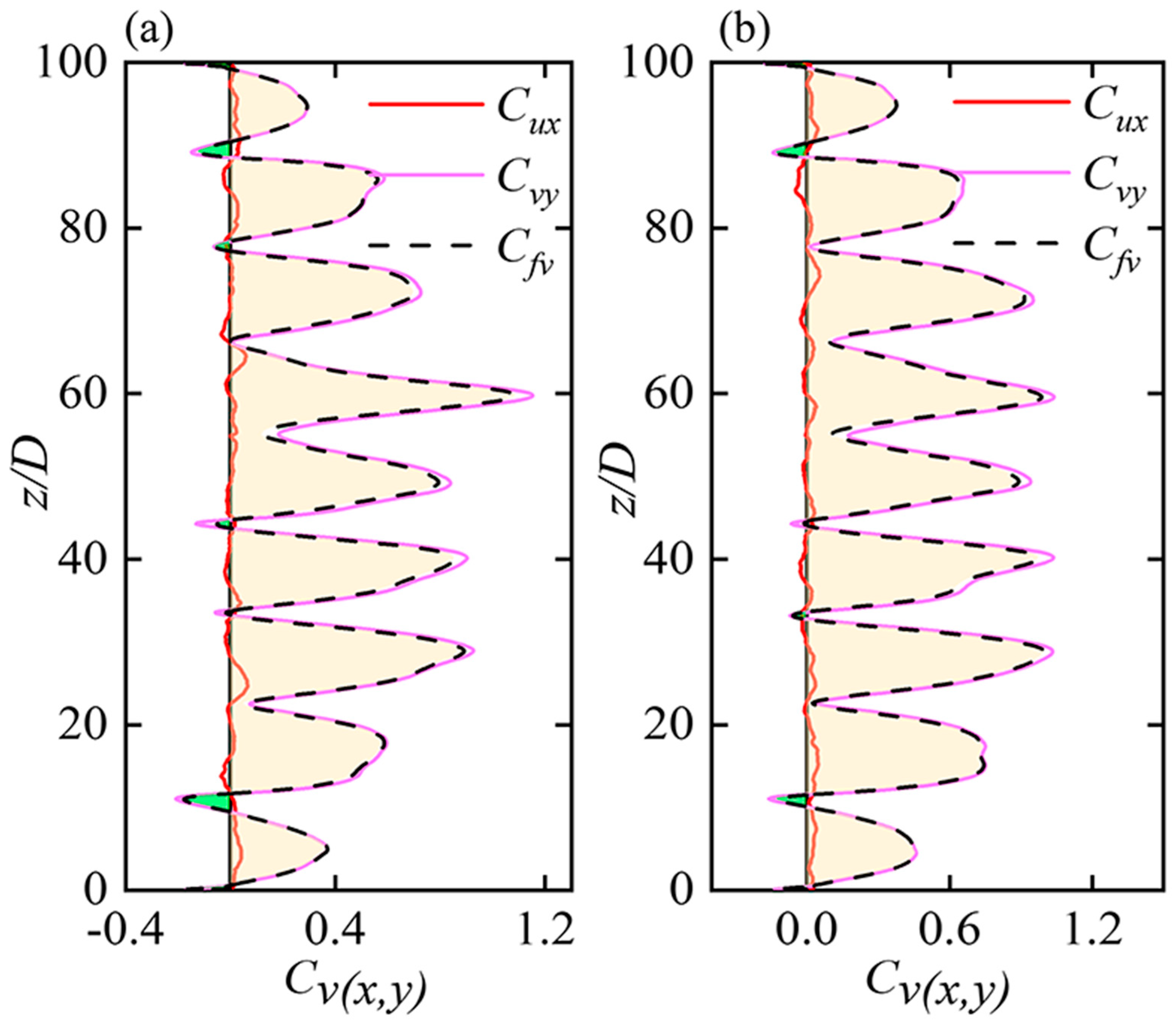
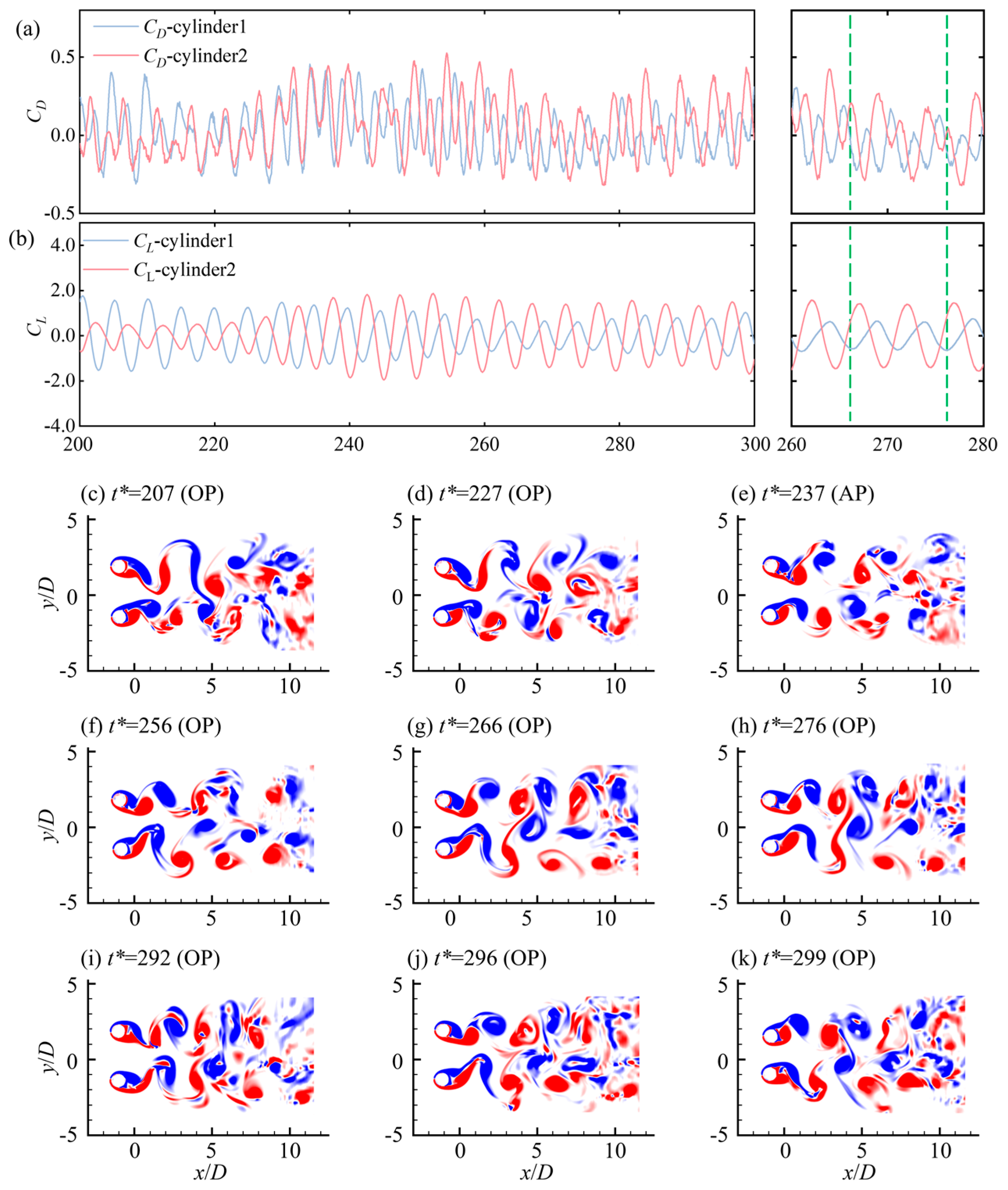
4.3. Hydrodynamic Forces and Energy Transfer
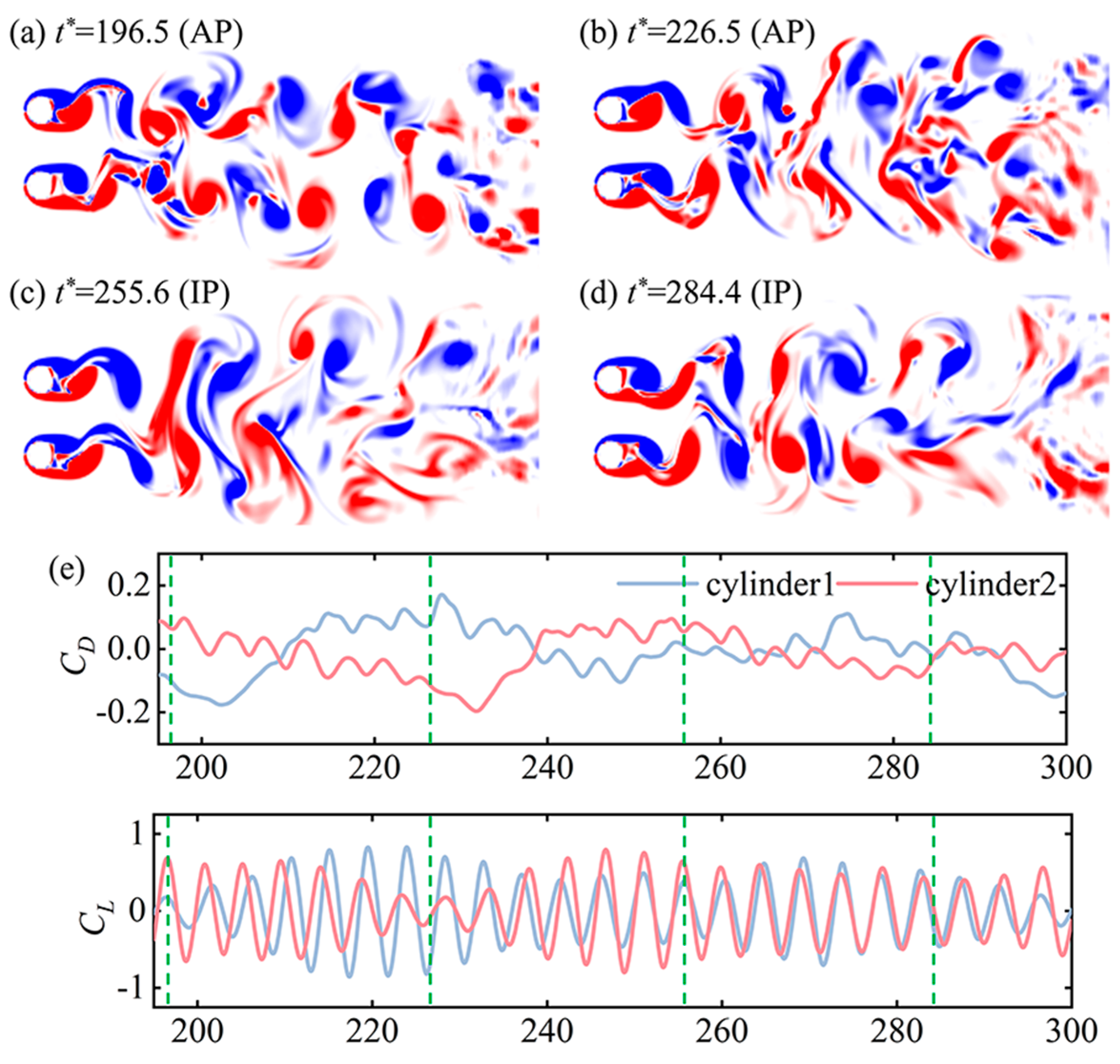
The spatial and temporal variations of fluctuations in drag and lift coefficients are illustrated in Figure 12. The time-averaged values at each spanwise location were adjusted, and the phase lag of lift coefficient along the span was shown for each cylinder. The force coefficient distribution was notably impacted by structural oscillation, especially in the CF direction. Oblique streaks of drag and lift coefficients were observed within the spatial-temporal domain, indicating non-simultaneous vortex shedding along the span. The phase exhibited waviness along the span, exemplified by a lift phase lag of −180° (Figure 12c,f), signifying anti-phase vortex shedding with respect to z/D = 0. Local peak values of lift phase aligned with CF anti-nodes and nodes, representing significant dislocations of vortex shedding in these regions. Fluctuations in lift and drag coefficients along the span were attributed to varying vortex shedding intensities. The observed discontinuities between neighboring spanwise cells implied the presence of vortex dislocations at different locations, with more dislocations than in stationary cylinders. Structural vibrations influenced interactions between vortices and cylinders, leading to pronounced fluctuations in lift and drag coefficients compared to stationary cylinders. A combination of standing and traveling behavior characterized the lift coefficients, showcasing more evident standing-wave components and asymmetrical distributions at different spanwise locations.
The spanwise distributions of mean and rms values in IL and CF directions are presented in Figure 13. The force coefficients of the two cylinders showed similar spanwise distribution, with slight variations of the magnitudes near the peaks and troughs of the profiles. Note that the mean lift of the two cylinders (Figure 13b) was closer to each other in general shapes along the span but in negative and positive values, respectively, similar to the case of stationary side-by-side cylinders (Figure 3b). However, a noticeable difference was that the cylinders showed smaller values of the repelling mean lift in the middle span than at the two ends. This implied a higher possibility of the existence of the IP vortex-shedding pattern in the middle span than that at the two ends, based on the fact that the IP wake generated a weaker repulsive force than the AP wake as mentioned in Section 3. Additionally, as presented in Figure 13c,d, the peaks and troughs of RMS drag and lift coefficients occurred around the anti-node or node locations of vibrations for both cylinders, respectively. In comparison to the stationary cylinders (Figure 3), lift and drag coefficient values in vibrating conditions were significantly amplified as the structures oscillated, mirroring the behavior observed in single cylinder scenarios [33,38,39].
Figure 14 shows the spanwise frequency distributions of the coefficients (drag and lift). The PSD of drag and lift coefficients exhibited a predominant frequency of 0.202, corresponding to the ninth mode distribution along the span. The predominant frequency aligned with the CF and IL vibrations (Figure 8), showing the lock-in occurrence in each plane. This dual lock-in effect was different from that seen in the single cylinder scenario, where lock-in happened solely in the CF direction. The IL direction’s lock-in also triggered more significant IL vibrations compared to a single cylinder. A similar IL lock-in phenomenon occurred with a single flexible cylinder positioned close to the bottom wall [40]. Additionally, the PSD of drag coefficient revealed several low-frequency elements and wide-range frequencies near 0.404, suggesting the combination of various shedding frequencies from vortices. Moreover, the primary frequency components of lift and drag coefficients for two fixed cylinders are denoted by red dashed lines, emphasizing a dominant frequency of 0.219, which exceeded those observed in the oscillating scenario. This indicated that reduced vortex shedding frequency can be excited under vibrating conditions in the same configurations as the stationary cylinders. An identical phenomenon was also noted in situations involving an isolated flexible cylinder in Bourguet and Triantafyllou [41].
The fluid forces exerted on cylinders can represent the nonlinear equilibrium state, allowing for the identification of fluid-structure energy transfer. The energy exchanges are vital to the VIV dynamic behaviors, both in its academic interest and application applications. To discover the relation between the vibration responses and vortex, the transfer energy coefficients between fluid and vibration were obtained via the fluid coefficient in phase with the vibration velocity in IL and CF directions [41], respectively, as follows:
C u x z = 2 T T C d z , t ζ ˙ x z , t d t 2 T T ζ ˙ x 2 z , t d t
C v y z = 2 T T   C l z , t ζ ˙ y z , t d t 2 T T   ζ ˙ y 2 z , t d t
The time-averaged value of this coefficient involving the IL and CF contributions is defined as:
C f v z = 2 T T C d z , t ζ ˙ x z , t + C l z , t ζ ˙ y z , t d t 2 T T ζ ˙ x 2 z , t + ζ ˙ y 2 z , t d t
The spanwise distributions of Cux, Cvy, and Cfv for two cylinders are presented in Figure 15. Positive values mean that the fluid provides energy to excite the cylinder to vibrate, whereas negative values show fluid damping structure oscillation. It is important to point out that the value of Cfv was not just equal to the sum of Cux and Cvy since there was a phase lag between them.
As shown in Figure 15, both cylinders exhibited similar distributions of energy transfer coefficients. Positive Cvy was widely spread along the span, with peak and tough values corresponding to the anti-nodes and nodes of vibration profiles, respectively. The profile of Cvy showed a great similarity to that of the IL and CF phase difference, reiterating the correlation between Φxy < 180° and the net energy transfer from surrounding flow to structural vibration. Different from the single flexible case where the Cvy was generally symmetrical distributed along the span [28], the Cvy exhibited asymmetrical distributions along two cylinders due to the proximity interferences. Moreover, the peaks of Cvy were more prominent in the middle span than those at the two ends, meaning that more energy was transferred to the cylinders there. It was noted that for statistically stable vibrations, energy transfer from and to the structural vibration balanced out, reaching a zero net energy transfer along the entire structure [28,41]. However, in the investigated time span 200 < t* < 300, the positive Cvy region was significantly larger than its negative counterparts, indicating significant net energy was transferred from the fluid to the cylinders, thereby intensifying the vibrations for both cylinders, as demonstrated by the intensified IL vibrations shown in Figure 7a,b. Therefore, the excitation mechanisms can be explained in the manner that net energy was transferred from the surrounding flow to the structural vibrations at a higher mode (the ninth mode), then shifted to lower-mode (the second and third modes) vibrations through mode competition, and finally excited lower-mode vibrations with enlarging amplitude. Note that due to the irregular vibration in the FF pattern and the low-frequency switching of the gap flow, achieving the statistically stable state required a much longer simulation time which was computationally forbidden for 3-D numerical simulations. Despite this, we are confident that the excitation mechanisms identified were consistent and would differ only marginally from those derived from long-time DNS results.
For energy transfer in the IL direction, the Cux fluctuated between the positive and negative values along the span, but within a very small range. Compared to the profiles of Cvy, Cux showed fluctuations with a higher wavenumber. That is, within a vibration cell, the profile of Cux generally displayed positive and negative regions, showing a doubled variation frequency. As for the total energy transfer Cfv, it displayed an overall resemblance with Cvy along the spanwise, which suggested that the CF component played an important role in the total distribution of energy transfer. This similarity was also noted in Bourguet et al. [36] and Fan et al. [34] regarding the VIV of a single flexible cylinder.

4.4. Wake Patterns

The primary structures for the flexible cylinder were highly three-dimensional, exhibiting a strong correlation with the spatial-temporal vibration dynamics and hydrodynamic forces. Figure 16 illustrates the wake structures of the side-by-side flexible cylinders. Figure 16a,b display instantaneous iso-surfaces of three-dimensional vortex structures from different perspectives, while Figure 16c–k present two-dimensional vortex shedding contours at typical spanwise locations.
In Figure 16a, it can be observed that the spanwise vortex tubes aligned locally parallel to the deformed cylinder axis. Note that at anti-node (z/D = 6, 17, 28, 39, and 50) of vibration responses, the shear layer of the cylinders was less stretched under significant vibrations, resulting in the vortex shedding occurring at closer proximity to the cylinders. In the far wake, due to the motion of cylinders, vortex tubes were broken up into separated cells, with intense streamwise vortex filaments (white) mixed, showing a strong three-dimensional wake. As shown in Figure 16c–k, each cylinder showed a ‘2S’ vortex shedding pattern in the near wake. However, the wake patterns for the two cylinders were significantly different along the span. For example, at the same instant, an IP synchronization pattern was observed at z/D = 23 (Figure 16f); an out-of-phase (OP) pattern was exhibited at z/D = 17, 28, and 50 (Figure 16e,g,k), while other spanwise locations commonly showed the AP synchronization pattern (Figure 16c,d,h–j). The variations of the vortex shedding patterns along the span also contributed to the large spanwise fluctuations of the fluid forces and the vibration amplitudes of the two cylinders.
To illustrate the intricate characteristics of wake transition and hydrodynamics clearly, the evolution of fluid forces and vortex-shedding patterns over time at z/D = 28 is depicted in Figure 17. The vortex shedding of the two side-by-side cylinders was in a flip-flopping pattern, showing an alternating narrow and wide wake behind the cylinders. In this FF pattern, when the gap flow was biased toward Cyl-1 (Figure 17c,d), the shear layers of Cyl-1 were pushed closer to the cylinder base, creating a negative pressure zone closer to Cyl-1. Consequently, the magnitudes of the lift and drag coefficients of Cyl-1 were higher than that of Cyl-2, as indicated in Figure 17a,b. However, the vortices behind Cyl-1 were more concentrated with a narrow spacing in the wake. However, the scenario flipped over during the time span t* = 256–299, as shown in Figure 17f–k. A transition between different scenarios can be seen at t* = 237 (Figure 17e) when the AP vortex-shedding pattern was seen. Note that, the IP pattern barely appeared in the wake, because a phase difference persisted in the vortex shedding for two cylinders. The FF wake transition in the vibrating conditions contributed to the intermittent modifications in vibration frequency, as evidenced by the time instability of frequency components in the wavelet analysis (Figure 11). This transition was also different from that of the two side-by-side stationary cylinders, where the FF pattern was more regular, as shown in Figure 6. This also indicated the significant modulational effects of vibration on the wake patterns. Moreover, due to the mutual interference between the side-by-side cylinders, the strengths and shapes of gap-side and freestream side vortices showed large differences for each cylinder, amplifying the lift fluctuations and changing the dominant frequency to the resultant ratio of 1 between the lift and drag frequencies, as compared to the single cylinder condition.

5. Conclusions

The vortex-induced vibration of two side-by-side flexible cylinders was numerically investigated via three-dimensional DNS with L/D = 100, s/D = 2.5, and Re = 350. The main findings on temporal-spatial evolution and the mechanism of vibration responses and wake patterns are summarized as follows:
A combined standing-traveling wave pattern was excited for the IL vibrations of the two cylinders, while the CF vibration exhibited a standing-wave characteristic. The ninth vibration mode was predominantly identified in both the IL and CF directions. Mode competition excited among other lower frequency responses due to the proximity effect from the neighboring cylinder. The dominant frequency between IL and CF vibrations was identical for each cylinder, yet different from the IL to CF ratio of 2 for the isolated cylinder condition. The motion trajectories of the two cylinders were both in oval shapes but with opposite directions, respectively.
Repulsive mean lift coefficients were excited for two cylinders in both the stationary and vibrating conditions, due to the asymmetrical vortex shedding for each cylinder in this smaller spacing. Compared with the stationary condition, the lift and drag coefficients were significantly increased but with a lower vortex-shedding frequency. Positive energy transfer occurred predominantly excited along the span due to the excitation via the vortex shedding from the cylinder itself and the neighboring one. The energy input was then shifted to low-frequency vibrations and excited enlarged lower-mode vibrations.
The flip-flopping wake pattern was observed for both the stationary and vibrating conditions, showing the in-phase, anti-phase, and out-of-phase vortex-shedding patterns simultaneously along the cylinders. For the vibrating case, the AP, IP, and OP patterns transited more irregularly over time than in the stationary case. Spanwise vortex dislocations were excited near the anti-nodes of the cylinder response profiles.
Overall, the vibration modes and wake patterns of two side-by-side flexible cylinders at s/D = 2.5 were analyzed in detail. The conclusions help understand the vortex-induced vibration of the risers in ocean engineering. Future work should focus on more detailed comparative consideration of different spacing ratios and at the same time, consider the real and more complex marine environment, such as oscillating flow and shear flow.

Author Contributions

Conceptualization, S.C. and L.Z.; methodology, Z.Z. and C.J.; software, S.C.; validation, S.C., L.Z. and Z.Z.; formal analysis, S.C.; investigation, L.Z.; resources, Z.Z. and C.J.; data curation, S.C. and Z.Z.; writing—original draft preparation, S.C.; writing—review and editing, C.J., L.Z. and Z.Z.; visualization, S.C.; supervision, Z.Z. and C.J.; project administration, Z.Z. and C.J.; funding acquisition, Z.Z. and C.J. All authors have read and agreed to the published version of the manuscript.

Funding

This research was funded by National Natural Science Foundation of China (grant number 51779172, 52179076) and the Open Fund of State Key Laboratory of Hydraulics and Mountain River Engineering, Sichuan University (grant number 2310).

Data Availability Statement

The data that support the findings of this study are available from the corresponding author upon reasonable request.

Acknowledgments

We gratefully acknowledge the support of Tianjin University and Sichuan University, China, for funding this work.

Conflicts of Interest

The authors declare no conflicts of interest.

Appendix A

To validate the accuracy of the current numerical solution, simulations were conducted for the VIV of a long flexible cylinder and flow around two side-by-side cylinders. The obtained results were then compared with the relevant literature. Table A1 and Table A2 outline the comparisons of root mean square (RMS) amplitudes ((Ax)rms, (Ay)rms), vibration frequencies in in-line and cross-flow directions (fx, fy), average drag/lift coefficients ((CD)mean, (CL)mean) and their RMS values ((CD)rms, (CL)rms), as well as the Strouhal number (St), defined as St = fLD/U, where fL represents the dominant lift frequency.
Table A1 demonstrates a close agreement between the current numerical findings and those of Bourguet et al. [33] for the VIV of a flexible cylinder case, encompassing vibration amplitudes, frequencies, and fluid forces under identical configurations. Additionally, the results from the simulation of flow past two stationary side-by-side cylinders at s/D = 2.5 were compared with the literature data, showing excellent conformity as presented in Table A2. Overall, the results in Table A1 and Table A2 exhibited strong alignment with the cited literature in terms of vibration responses, fluid forces, and the Strouhal number, boasting a maximum deviation of less than 5%. This underscores the high precision and reliability of the current methodology.
Table A1. Comparison of vibration and hydrodynamic properties for VIV of a flexible isolated cylinder with Re = 500, L/D = 50.
(Ax)rms(Ay)rmsfxfy(CD)mean(CD)rms(CL)rms
Present0.1450.5440.3400.1702.0140.6570.952
Bourguet et al. (2015) [33]0.1490.5320.3420.1712.1000.6770.915
Difference (%)2.682.260.580.584.102.924.04
Table A2. Comparison of hydrodynamic properties for two side-by-side cylinders with Re = 100, s/D = 2.5. Values in parentheses indicate a percentage difference against results with present.
(CD)mean(CL)meanSt
Present1.4240.1760.163
Kang (2003) [42]1.43 (0.42)0.178 (1.14)0.164 (0.61)
Lee et al. (2009) [43]1.423 (0.07)0.178 (1.14)-
Bao et al. (2013) [44]1.431 (0.49)0.177 (0.57)-
Carini et al. (2014) [45]1.408 (1.12)-0.163 (0.00)

References

  1. Zdravkovich, M.M.; Bearman, P.W. Flow Around Circular Cylinders—Volume 1: Fundamentals. J. Fluids Eng. 1998, 120, 216. [Google Scholar] [CrossRef]
  2. Ren, C.; Liu, Z.; Cheng, L.; Tong, F.; Xiong, C. Three-dimensional wake transitions of steady flow past two side-by-side cylinders. J. Fluid Mech. 2023, 972, A17. [Google Scholar] [CrossRef]
  3. Huera-Huarte, F.J.; Gharib, M. Flow-induced vibrations of a side-by-side arrangement of two flexible circular cylinders. J. Fluids Struct. 2011, 27, 354–366. [Google Scholar] [CrossRef]
  4. Liu, Y.; Li, P.; Wang, Y.; Liu, L.-H.; Wang, F.; Guo, H.-Y.; Fu, Q. An Experimental Study on Dynamics Features of Three Side-by-Side Flexible Risers Undergoing Vortex-Induced Vibrations in A Uniform Flow. China Ocean Eng. 2020, 34, 500–512. [Google Scholar] [CrossRef]
  5. Zdravkovich, M.M. The effects of interference between circular cylinders in cross flow. J. Fluids Struct. 1987, 1, 239–261. [Google Scholar] [CrossRef]
  6. Wang, Z.J.; Zhou, Y. Vortex interactions in a two side-by-side cylinder near-wake. Int. J. Heat Fluid Flow 2005, 26, 362–377. [Google Scholar] [CrossRef]
  7. Afgan, I.; Kahil, Y.; Benhamadouche, S.; Sagaut, P. Large eddy simulation of the flow around single and two side-by-side cylinders at subcritical Reynolds numbers. Phys. Fluids 2011, 23, 075101. [Google Scholar] [CrossRef]
  8. Zhou, Y.; Feng, S.X.; Alam, M.M.; Bai, H.L. Reynolds number effect on the wake of two staggered cylinders. Phys. Fluids 2009, 21, 125105. [Google Scholar] [CrossRef]
  9. Supradeepan, K.; Roy, A. Characterisation and analysis of flow over two side by side cylinders for different gaps at low Reynolds number: A numerical approach. Phys. Fluids 2014, 26, 063602. [Google Scholar] [CrossRef]
  10. Kim, S.; Alam, M.M. Characteristics and suppression of flow-induced vibrations of two side-by-side circular cylinders. J. Fluids Struct. 2015, 54, 629–642. [Google Scholar] [CrossRef]
  11. Chen, W.; Ji, C.; Xu, W.; Liu, S.; Campbell, J. Response and wake patterns of two side-by-side elastically supported circular cylinders in uniform laminar cross-flow. J. Fluids Struct. 2015, 55, 218–236. [Google Scholar] [CrossRef]
  12. Munir, A.; Zhao, M.; Wu, H.; Lu, L. Effects of gap ratio on flow-induced vibration of two rigidly coupled side-by-side cylinders. J. Fluids Struct. 2019, 91, 102726. [Google Scholar] [CrossRef]
  13. Xu, W.; Wu, H.; Sha, M.; Wang, E. Numerical study on the flow-induced vibrations of two elastically mounted side-by-side cylinders at subcritical Reynolds numbers. Appl. Ocean Res. 2022, 124, 103191. [Google Scholar] [CrossRef]
  14. Ramberg, S.E. The effects of yaw and finite length upon the vortex wakes of stationary and vibrating circular cylinders. J. Fluid Mech. 1983, 128, 81–107. [Google Scholar] [CrossRef]
  15. Silva-Leon, J.; Cioncolini, A. Effect of Inclination on Vortex Shedding Frequency Behind a Bent Cylinder: An Experimental Study. Fluids 2019, 4, 100. [Google Scholar] [CrossRef]
  16. Zhou, Y.; Wang, Z.J.; So, R.M.C.; Xu, S.J.; Jin, W. Free vibrations of two side-by-side cylinders in a cross-flow. J. Fluid Mech. 2001, 443, 197–229. [Google Scholar] [CrossRef]
  17. So, R.M.C.; Wang, X.Q. Vortex-Induced Vibrations of Two Side-by-Side Euler-Bernoulli Beams. J. Sound Vib. 2003, 259, 677–700. [Google Scholar] [CrossRef]
  18. Han, Q.; Ma, Y.; Xu, W.; Zhang, S. An experimental study on the hydrodynamic features of two side-by-side flexible cylinders undergoing flow-induced vibrations in a uniform flow. Mar. Struct. 2018, 61, 326–342. [Google Scholar] [CrossRef]
  19. Xu, W.; Cheng, A.; Ma, Y.; Gao, X. Multi-mode flow-induced vibrations of two side-by-side slender flexible cylinders in a uniform flow. Mar. Struct. 2018, 57, 219–236. [Google Scholar] [CrossRef]
  20. Ji, C.; Munjiza, A.; Williams, J.J.R. A novel iterative direct-forcing immersed boundary method and its finite volume applications. J. Comput. Phys. 2012, 231, 1797–1821. [Google Scholar] [CrossRef]
  21. Peskin, C.S. The immersed boundary method. Acta Numer. 2003, 11, 479–517. [Google Scholar] [CrossRef]
  22. Van der Vorst, H.A. Bi-CGSTAB: A Fast and Smoothly Converging Variant of Bi-CG for the Solution of Nonsymmetric Linear Systems. SIAM J. Sci. Stat. Comput. 1992, 13, 631–644. [Google Scholar] [CrossRef]
  23. Vandiver, J.K.; Jaiswal, V.; Jhingran, V. Insights on vortex-induced, traveling waves on long risers. J. Fluids Struct. 2009, 25, 641–653. [Google Scholar] [CrossRef]
  24. Dahl, J.M.; Hover, F.S.; Triantafyllou, M.S.; Oakley, O.H. Dual resonance in vortex-induced vibrations at subcritical and supercritical Reynolds numbers. J. Fluid Mech. 2010, 643, 395–424. [Google Scholar] [CrossRef]
  25. Gao, Y.; Zhang, Z.; Zou, L.; Zong, Z.; Yang, B. Effect of boundary condition and aspect ratio on vortex-induced vibration response of a circular cylinder. Ocean Eng. 2019, 188, 106244. [Google Scholar] [CrossRef]
  26. Bourguet, R.; Triantafyllou, M.S. The onset of vortex-induced vibrations of a flexible cylinder at large inclination angle. J. Fluid Mech. 2016, 809, 111–134. [Google Scholar] [CrossRef]
  27. Jiang, H.; Cheng, L.; Draper, S.; An, H. Two- and three-dimensional instabilities in the wake of a circular cylinder near a moving wall. J. Fluid Mech. 2017, 812, 435–462. [Google Scholar] [CrossRef]
  28. Zhang, Z.; Ji, C.; Alam, M.M.; Xu, D. Dynamics and wake structure of a near-wall flexible cylinder. Int. J. Mech. Sci. 2022, 222, 107229. [Google Scholar] [CrossRef]
  29. Chen, W.L.; Ji, C.N.; Xu, D. Vortex-induced vibrations of two side-by-side circular cylinders with two degrees of freedom in laminar cross-flow. Comput. Fluids 2019, 193, 104288. [Google Scholar] [CrossRef]
  30. Yan, Y.; Chen, W.; Zhang, Z.; Ji, C.; Srinil, N. Features and mechanisms of asymmetric wake evolution downstream of two parallel circular cylinders. Phys. Fluids 2023, 35, 107132. [Google Scholar] [CrossRef]
  31. Williamson, C.H.K.; Govardhan, R. Vortex-Induced Vibrations. Annu. Rev. Fluid Mech. 2004, 36, 413–455. [Google Scholar] [CrossRef]
  32. Zhou, Y.; Zhang, H.J.; Yiu, M.W. The turbulent wake of two side-by-side circular cylinders. J. Fluid Mech. 2002, 458, 303–332. [Google Scholar] [CrossRef]
  33. Bourguet, R.; Em Karniadakis, G.; Triantafyllou, M.S. On the validity of the independence principle applied to the vortex-induced vibrations of a flexible cylinder inclined at 60°. J. Fluids Struct. 2015, 53, 58–69. [Google Scholar] [CrossRef]
  34. Fan, D.X.; Wang, Z.C.; Triantafyllou, M.S.; Karniadakis, G.E. Mapping the properties of the vortex-induced vibrations of flexible cylinders in uniform oncoming flow. J. Fluid Mech. 2019, 881, 815–858. [Google Scholar] [CrossRef]
  35. Dahl, J.M.; Hover, F.S.; Triantafyllou, M.S.; Dong, S.; Karniadakis, G.E. Resonant vibrations of bluff bodies cause multivortex shedding and high frequency forces. Phys. Rev. Lett. 2007, 99, 144503. [Google Scholar] [CrossRef] [PubMed]
  36. Bourguet, R.; Karniadakis, G.E.; Triantafyllou, M.S. Vortex-induced vibrations of a long flexible cylinder in shear flow. J. Fluid Mech. 2011, 677, 342–382. [Google Scholar] [CrossRef]
  37. Bourguet, R.; Lucor, D.; Triantafyllou, M.S. Mono- and multi-frequency vortex-induced vibrations of a long tensioned beam in shear flow. J. Fluids Struct. 2012, 32, 52–64. [Google Scholar] [CrossRef]
  38. Jauvtis, N.; Williamson, C.H.K. The effect of two degrees of freedom on vortex-induced vibration at low mass and damping. J. Fluid Mech. 2004, 509, 23–62. [Google Scholar] [CrossRef]
  39. Franzini, G.R.; Gonçalves, R.T.; Meneghini, J.R.; Fujarra, A.L.C. One and two degrees-of-freedom Vortex-Induced Vibration experiments with yawed cylinders. J. Fluids Struct. 2013, 42, 401–420. [Google Scholar] [CrossRef]
  40. Zhang, Z.; Ji, C.; Xu, D.; Zhu, H.; Derakhshandeh, J.F.; Chen, W. Effect of yaw angle on vibration mode transition and wake structure of a near-wall flexible cylinder. Phys. Fluids 2022, 34, 077106. [Google Scholar] [CrossRef]
  41. Bourguet, R.; Triantafyllou, M.S. Vortex-induced vibrations of a flexible cylinder at large inclination angle. Philos. Trans. R. Soc. A Math. Phys. Eng. Sci. 2015, 373, 20140108. [Google Scholar] [CrossRef] [PubMed]
  42. Kang, S. Characteristics of flow over two circular cylinders in a side-by-side arrangement at low Reynolds numbers. Phys. Fluids 2003, 15, 2486–2498. [Google Scholar] [CrossRef]
  43. Lee, D.S.; Ha, M.Y.; Yoon, H.S.; Balachandar, S. A numerical study on the flow patterns of two oscillating cylinders. J. Fluids Struct. 2009, 25, 263–283. [Google Scholar] [CrossRef]
  44. Bao, Y.; Zhou, D.; Tu, J. Flow characteristics of two in-phase oscillating cylinders in side-by-side arrangement. Comput. Fluids 2013, 71, 124–145. [Google Scholar] [CrossRef]
  45. Carini, M.; Giannetti, F.; Auteri, F. On the origin of the flip–flop instability of two side-by-side cylinder wakes. J. Fluid Mech. 2014, 742, 552–576. [Google Scholar] [CrossRef]
Figure 1. Deformed cylinders and boundary conditions of the computational domain. The red dashed rectangular shape indicates the uniform mesh region.
Energies 17 02741 g001
Figure 2. Mesh distributions covering the entire flow domain and a local refinement near the cylinder. A uniform mesh grid spacing (∆x = ∆y = D/32) was utilized around the cylinder (white circle) in a rectangular region (outlined in red dash line).
Energies 17 02741 g002
Figure 3. Spatial-temporal evolutions of the (a,c) IL and (b,d) CF force coefficients for (a,b) Cyl-1 and (c,d) Cyl-2.
Energies 17 02741 g003
Figure 4. (a,b) Mean and (c,d) RMS values of the (a,c) drag and (b,d) lift coefficients along the cylinder span for the flow around.
Energies 17 02741 g004
Figure 5. Instantaneous iso-surfaces (a,b) of λ2 = −1 (colored by spanwise vorticity, ωz) at t* = 350, (cf) instant 2-D contours of the spanwise vorticity in the (x, y) plane of different spanwise locations (marked by the black dashed lines in (a)) at the same instant (t* = 350). The red and blue represent counterclockwise and clockwise rotating spanwise vortices, respectively.
Energies 17 02741 g005
Figure 6. (ad) Two-dimensional vortex shedding contours at z/D = 50 for different instants. The red and blue represent counterclockwise and clockwise rotating spanwise vortices, respectively. (e) Time series of the drag and lift coefficients of z/D = 50. The green dashed lines (e) correspond to the instants of the wake in (ad).
Energies 17 02741 g006
Figure 7. The spanwise evolutions of the mean and maximum vibration values (i), and the sptial-temporal displacement (ii) for Cyl-1 (a,c) and Cyl-2 (b,d) in the IL (a,b) and CF (c,d) directions.
Energies 17 02741 g007
Figure 8. PSD of the (a) in-line and (b) cross-flow displacement for cylinder 1.
Energies 17 02741 g008
Figure 9. (a) Time-averaged phase difference between the IL and CF displacements along the span for two cylinders. Vibration trajectories of (b) Cyl-2 and (c) Cyl-1 at different spanwise locations. The arrow represents the direction of the cylindrical trajectory.
Energies 17 02741 g009
Figure 10. Instantaneous mode decomposition of IL (a,e) and CF (c,g) displacements with time, and percentage of modes per order for IL (b,f) and CF (d,h) for Cyl-1 (ad) and Cyl-2 (eh).
Energies 17 02741 g010
Figure 11. Instantaneous frequency at different spanwise locations for the (a,c) in-line and (b,d) cross-flow oscillations of Cyl-1 (a,b) and Cyl-2 (c,d). The red represent the positive proportion and blue represent the negative proportion.
Energies 17 02741 g011aEnergies 17 02741 g011b
Figure 12. Spatial-temporal distributions of (a,d) drag coefficients, (b,e) lift coefficients, and (c,f) relative phase angle of the lift coefficients along the span for (ac) Cyl-1 and (df) Cyl-2.
Energies 17 02741 g012
Figure 13. (a,b) Mean and (c,d) RMS values of the (a,c) drag and (b,d) lift coefficients along the cylinder span for the vibration.
Energies 17 02741 g013
Figure 14. PSD of fluid force coefficients along the vibrating cylinder span. (a) Drag and (b) lift for Cyl-1. The lift and drag frequencies of the stationary cylinder conditions are indicated by the red dashed lines.
Energies 17 02741 g014
Figure 15. Spanwise distribution of time-averaged transferred energy coefficients in IL (Cux) and CF (Cvy) motions as well as the total values (Cfv) including contributions from both the IL and CF directions for the two cylinders of Cyl-1 (a) and Cyl-2 (b). The excitation and damping regions of the Cfv are denoted as the orange and green shades, respectively.
Energies 17 02741 g015
Figure 16. Instantaneous wake structures (a,b) iso-surfaces (λ2 = −1) of the spanwise vorticity and (ck) 2-D contours of the spanwise vorticity in the (x, y) plane of different spanwise locations.
Energies 17 02741 g016
Figure 17. (a,b) Time histories of the force coefficients (left), and the locally enlarged diagram at t* = 260~280 (right), where the green dotted lines correspond to t* = 266 and 276. (ck) Two-dimensional vortex shedding contours at different instants with z/D = 28. The red and blue represent counterclockwise and clockwise rotating spanwise vortices, respectively.
Energies 17 02741 g017
Disclaimer/Publisher’s Note: The statements, opinions and data contained in all publications are solely those of the individual author(s) and contributor(s) and not of MDPI and/or the editor(s). MDPI and/or the editor(s) disclaim responsibility for any injury to people or property resulting from any ideas, methods, instructions or products referred to in the content.

