Article

Intelligent Type-2 Fuzzy Logic Controller for Hybrid Microgrid Energy Management with Different Modes of EVs Integration

Department of Electrical Engineering, College of Engineering at Yanbu, Taibah University, Yanbu 41911, Saudi Arabia
Energies 2024, 17(12), 2949; https://doi.org/10.3390/en17122949
Submission received: 28 April 2024 / Revised: 27 May 2024 / Accepted: 5 June 2024 / Published: 14 June 2024
(This article belongs to the Special Issue New Insights into Microgrids and Renewable Energy Systems)

Abstract

:
The rapid integration of renewable energy sources (RES) and the electrification of transportation have significantly transformed modern energy infrastructures, emphasizing the need for efficient and flexible energy management systems. This study presents an intelligent, variable-fed, Type-2 Fuzzy Logic Controller (IT2FLC) designed for optimal management of Hybrid Microgrid (HMG) energy systems, specifically considering different modes of Electric Vehicles (EVs) integration. The necessity of this study arises from the challenges posed by fluctuating renewable energy outputs and the uncoordinated charging practices of EVs, which can lead to grid instability and increased operational costs. The proposed IT2FLC is based on comprehensive mathematical modeling that captures complex interactions among HMG components, including Doubly Fed Induction Generator (DFIG) units, photovoltaic (PV) systems, utility AC power, and EV batteries. Utilizing a yearly dataset for simulation, this work examines the HMG’s flexibility and adaptability under dynamic conditions managed by the proposed intelligent controller. A Simulink-based model is built for this study to replicate the dynamical operation of the HMG and test the precise and real-time decision-making capability of the proposed IT2FLC. The results demonstrate the IT2FLC’s superior performance, achieving a substantial cost avoidance of nearly $3,750,000 and efficient energy balance, affirming its potential to sustain optimal energy utilization under stochastic conditions. Additionally, the results attest that the proposed IT2FLC significantly enhances the resilience and economic feasibility of hybrid microgrids, achieving a balanced energy exchange with the utility grid and efficient utilization of EV batteries, proving to be a superior solution for optimal operation of hybrid grids.

1. Introduction

As energy infrastructures undergo significant restructuring to accommodate the shifting dynamics of the energy landscape, marked by the incorporation of renewable energy sources (RES) and the electrification of transportation, hybrid microgrids (HMGs) are emerging as central components in the evolution towards smarter, cleaner grids [1,2]. In contrast to traditional large-scale energy grids, HMGs offer a more reliable and efficient electricity supply with reduced carbon emissions. HMGs also exhibit greater flexibility than conventional power grids, possessing the capability to swiftly adapt their power output. Defined as active agents within a low-voltage network, HMGs can function in both grid-connected and islanded modes [3]. Nevertheless, the variability of RES and challenges posed by the extensive integration of Electric Vehicles (EVs) often lead HMGs to rely heavily on the main AC grid for energy, potentially impacting their economic feasibility as a viable alternative in energy management strategies.
The global efforts to advance transportation electrification add complexity to the modernization of energy infrastructures. Planned transportation electrification is important for a sustainable energy future, as both power systems and transportation sectors are major contributors to global greenhouse gas (GHG) emissions [4]. However, the widespread adoption of EVs introduces substantial challenges, notably uncoordinated charging practices that could lead to escalated peak loads, increased losses, voltage stability issues, and overloading distribution feeders [5]. Recent research has focused on energy management and control strategies to navigate the complexities introduced by EV integration [6,7]. For example, the authors in [4] explore the integration of one million EVs within a sub-region of the Southeast Electric Reliability Council (SERC), analyzing various charging and discharging scenarios. The findings highlight that typical power distribution feeders are ill-equipped to support extended EV charging sessions without severe overloads and potential service disruptions. Further [5] delineates one of the initial investigations into the grid impacts of uncoordinated EV integration, evaluating the technical, economic, and operational ramifications of assimilating 7.5 million EVs. The study posits that without strategic EV charging management—shifting from peak to off-peak periods—a significant surge in energy costs across the US interconnected network is inevitable. Moreover, [8] investigates the hourly operational impact of large-scale EV adoption on the power distribution grid, employing dynamic simulations to assess various integration scenarios. The outcomes reveal that uncoordinated charging violates voltage thresholds, overloads conditions, and increases energy costs for all connected consumers. Additionally [9], indicates that uncoordinated charging strategies contribute to peak demands at multiple nodes throughout the day, necessitating significant investments in enhancing the grid’s generation and transmission infrastructure. On the contrary, proper management of EVs charging yields significant benefits for the operation of the electric grid [10,11]. Therefore, smart energy management is essential to mitigate uncertainties associated with large-scale EV integration, underscoring the need for strategic approaches in the evolving energy landscape.
The emergence of hybrid AC/DC microgrids, encompassing both DC power sources—such as PV systems, wind power, and energy storages—and modern DC loads alongside major AC power infrastructures, has sparked significant interest in recent years. This interest is attributed to the unique amalgamation of AC and DC systems, offering combined benefits and positioning them as likely candidates for future distribution and transmission networks [12,13]. A pivotal element in the efficacy of hybrid AC/DC microgrids lies in robust control strategies and management schemes, ensuring stable and efficient operations across both grid-connected and stand-alone modes [14,15].
Among well-known mathematical-based algorithms, Fuzzy Logic systems are considered among the best approaches for solving complex energy management problems. Selecting suitable fuzzy rules and membership functions (MFs) is a pivotal task in fuzzy systems. For energy systems characterized by a minimal set of variables, operators typically encounter minimal difficulties in formulating the appropriate fuzzy rules and MFs. Yet, achieving optimal performance in complex systems like energy systems becomes a formidable challenge due to the intricate task of establishing coherent relationships among the rules. Several works have utilized classical FLC to achieve effective management strategies within energy-related paradigms. For example, [16] develops a 25-rule Fuzzy Logic controller for an energy management system in a residential microgrid aimed at smoothing grid power fluctuations and managing battery state without predictive methods. Similarly, [17] proposes a rule-based energy management scheme (REMS) for continuous EV charging at a uniform price using a photovoltaic-grid system. Their work models PV output, EV demand, and energy storage unit (ESU), aiming for constant price charging by managing energy flows and enhancing the valley filling during off-peak hours. Validated under diverse conditions and compared to standard grid charging, the proposed method shows a 16.1% reduction in charging cost and a 93.7% decrease in grid burden, with vehicle-to-grid (V2G) technology further improving the payback of the PV-grid system. In [18], the evolution of energy management systems (EMS) in grid-connected Microgrids (CMGs) is investigated, focusing on a Rule-based EMS for a residential multi-source MG with distributed energy sources and V2G technology. The authors attest that FLCs offer promising features for achieving optimal energy management. The other literature utilizing classical FLC includes hybrid microgrids [19,20,21,22]; multi-agent control of DC microgrids [23,24,25]; economic dispatch-based control [26], among others.
Type II Fuzzy Logic Controllers are increasingly recognized as effective tools for navigating the complexities of managing systems like energy networks. These advanced controllers, with their layered structure and enhanced capability to handle uncertainties, offer significant improvements over classical FLCs, especially in uncertain and imprecise environments. Type-2 FLCs provide greater robustness and flexibility by capturing higher degrees of uncertainty, resulting in more accurate and reliable control. Unlike classical FLCs, which utilize crisp membership functions, T2FLCs employ fuzzy membership functions that better represent real-world ambiguities, enhancing their effectiveness in dynamic and stochastic environments. The essence of Type II FLCs lies in their adeptness at managing a broader range of uncertainties, making them particularly suitable for hybrid microgrids and RES integrations. Several studies have considered Type-2 FLC in energy management. For example, [27] tackles Load Frequency Control (LFC) in islanded AC microgrids, incorporating diverse microsources to manage power balance. They utilized a type-II fuzzy PID controller enhanced by an improved-salp swarm optimization (I-SSO) algorithm for effective frequency and tie-line power regulation amidst uncertainties. Comparative analyses highlight the proposed controller’s improved performance over conventional controllers and optimization techniques, showcasing its efficacy in stabilizing multi-area islanded AC microgrids. In [28], a Fuzzy type 2 controller is introduced to address low-power factor issues in microgrids, focusing on DC microgrids. By improving transient responses and aiming for near-unity power factors, this controller outperforms classical FLC and PI controllers in dynamic response, steady-state error, and power quality standards, validated through MATLAB/Simulink and dSPACE platform tests. In [29], a method combining Type 2 FLC and Artificial Neural Networks (ANN) for PV fault analysis is presented, demonstrating both techniques’ efficacy in detecting specific PV faults like damaged modules and partial shading. Through experiments, it is shown that Type 2 Fuzzy and ANN have comparable detection performance, laying the foundation for the development of robust FLCs and ANNs suitable for diverse applications. The authors in [30] investigate the dynamic stability challenges posed by increased penetration of RES-based microgrids in power systems, highlighting the negative impact of reduced system inertia from renewable generation. It introduces a Type-2 fuzzy fractional order PID power system stabilizer (PSS), enhanced by a meta-heuristic hybrid algorithm, to improve oscillation damping and, thus, dynamic stability under diverse conditions. Several studies focus on utilizing Type-2 FLC in energy management, such as for AC microgrid control [31,32,33,34,35]; battery storage integration into DC microgrids [36,37,38], among other studies.
In the landscape of microgrid energy management, a notable gap exists in the literature regarding the extensive modeling of dynamics and uncertainty in microgrids. With significant research concentrating on Classical Fuzzy Logic Controller (CFLC) solutions, the intricate details characterizing microgrid operational dynamics are often overlooked. Such an oversight may lead to compromised results, marking a potential flaw in their conceptualization. This issue is compounded by the fact that most studies traditionally focus on either AC or DC microgrids in isolation, with little to no attention given to the application of classical or Type-2 fuzzy logic within the realm of hybrid microgrid configurations. This limited scope fails to capture the complex interplay between AC and DC systems and the unique challenges presented by hybrid microgrids, leaving a critical area of microgrid management and optimization relatively unexplored.
In response to the prevailing gaps in the microgrids management literature, particularly the oversight of the complex dynamics characterizing HMG systems, this work proposes a novel approach through the development of an intelligent, variable-fed Type-2 Fuzzy Logic Controller (IT2FLC). The proposed controller is distinguished by its capacity to accommodate real-time, variable inputs, enabling optimal energy management within HMG uncertain environments. The major contribution of this work is as follows:
  • Development of an intelligent controller capable of accommodating real-time, variable inputs. This controller is designed to achieve optimal energy management within HMG environments characterized by uncertainty.
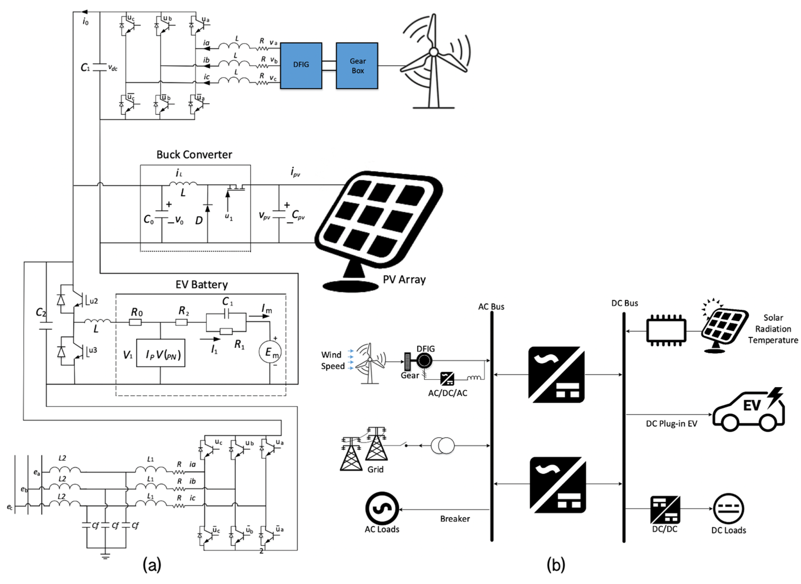
  • Detailed modeling of HMGs operational dynamics, including photovoltaic (PV) systems, Doubly Fed Induction Generator (DFIG) units, power electronics components, AC systems, and EV batteries. Addressing such complexities, often oversimplified in existing studies, is important to ensure accurate representation of microgrid dynamics.
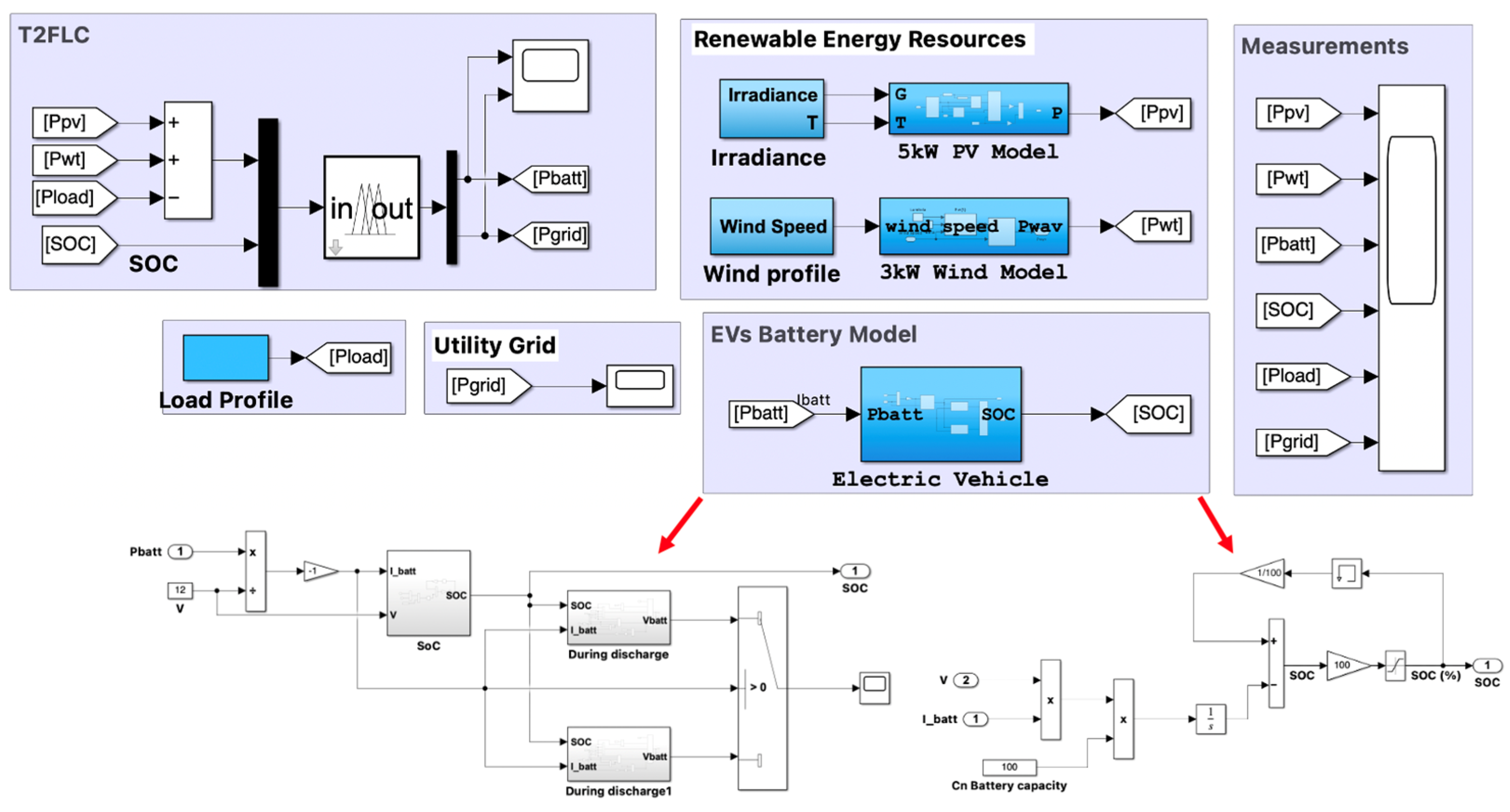
  • Creation of a comprehensive Simulink model to empirically validate the functionality of the proposed controller.
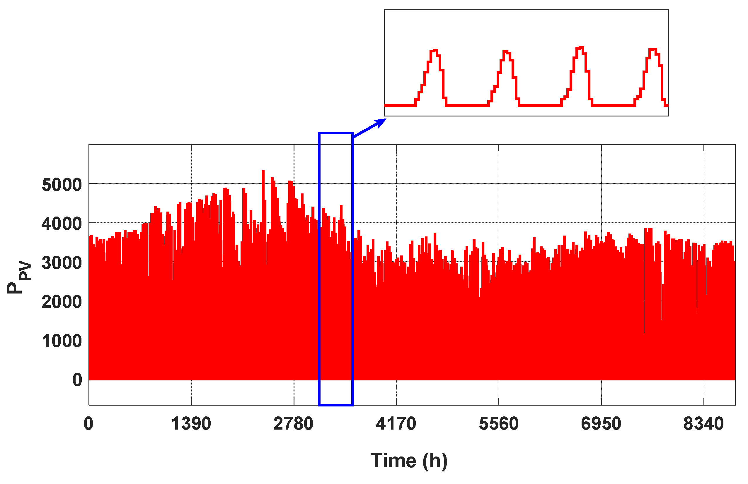
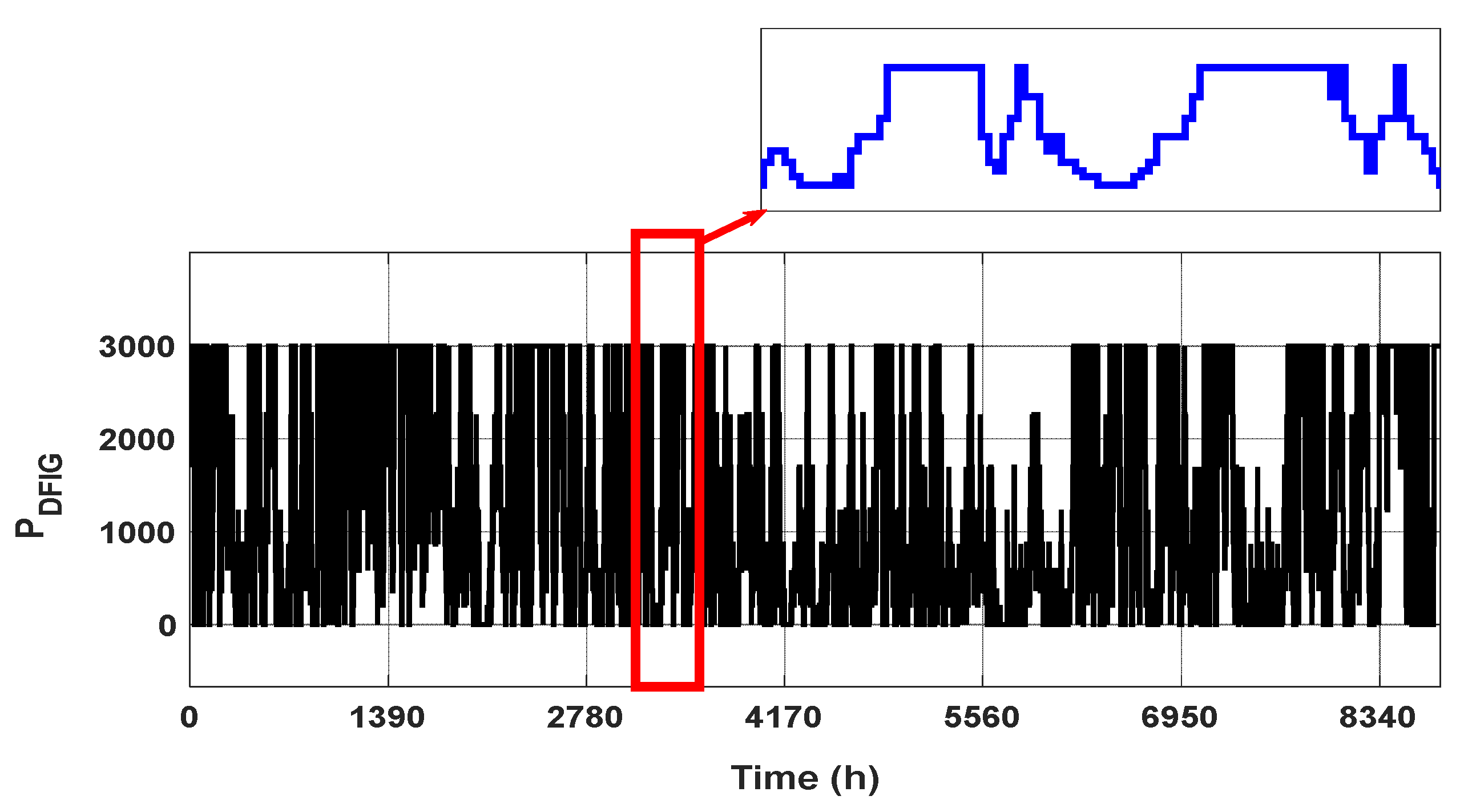
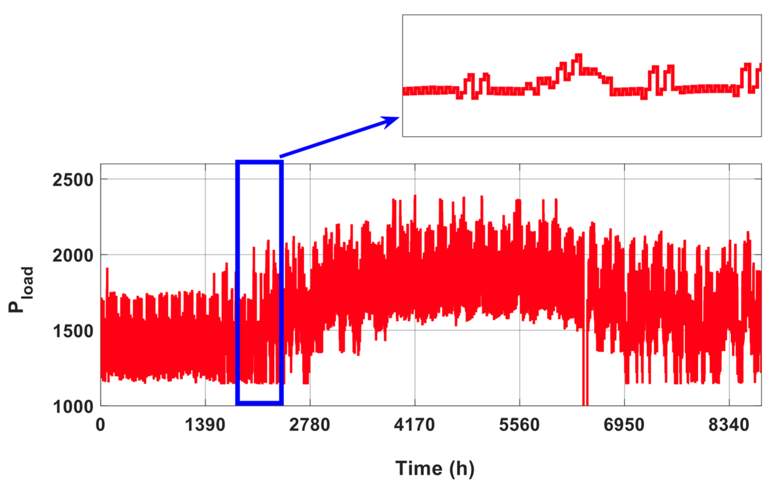
  • Utilization of a comprehensive dataset reflecting actual yearly variations in solar irradiance, wind velocities, real-life load demands, and EV battery behavior. This enables testing precise and real-time decision-making capability of the proposed controller under dynamic conditions.
This work is organized as follows: Section 2 provides a comprehensive mathematical modeling of the dynamic operation of HMGs and proposes intelligent, variable-fed IT2FLC; Section 3 provides detailed mathematical analysis of the fuzzy system utilized in this work and details the designed Simulink model that resembles the operation of HMG given uncertainty factors and real-time data; and Section 4 concludes the work with final remarks and discussion.

2. Mathematical Formulation

2.1. Mathematical Modeling of the Dynamics of Hybrid Microgrids Considering Different Modes of Electric Vehicles Integration

Figure 1 shows a system architecture of HMGs from both circuit-based design (left), and component-based design (right). To ensure the reliability and stability of operations within a HMG system across various conditions, it is imperative to maintain a balance between energy supply and demand. This work assumes the HMG system operates under three conditions:
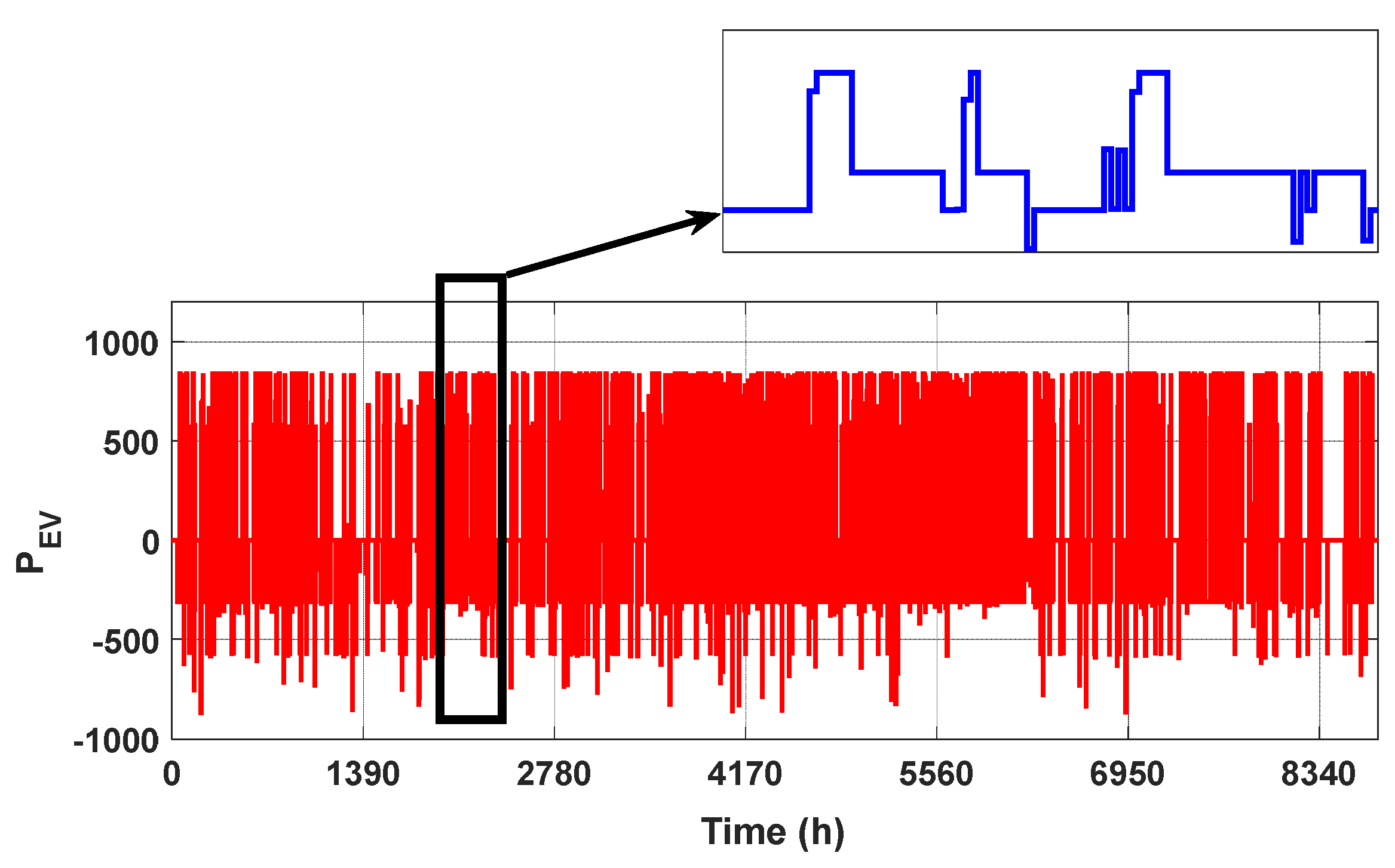
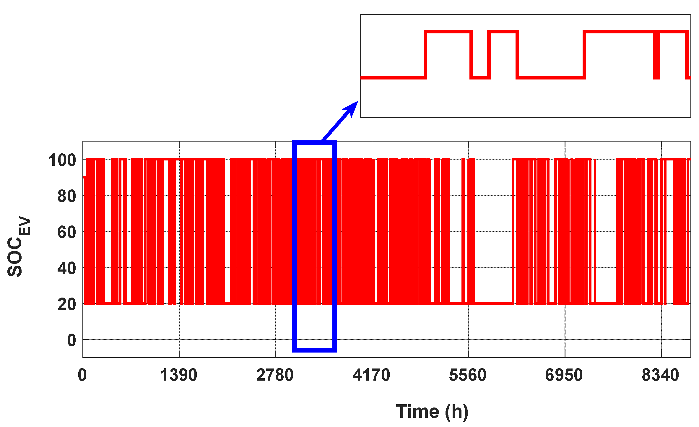
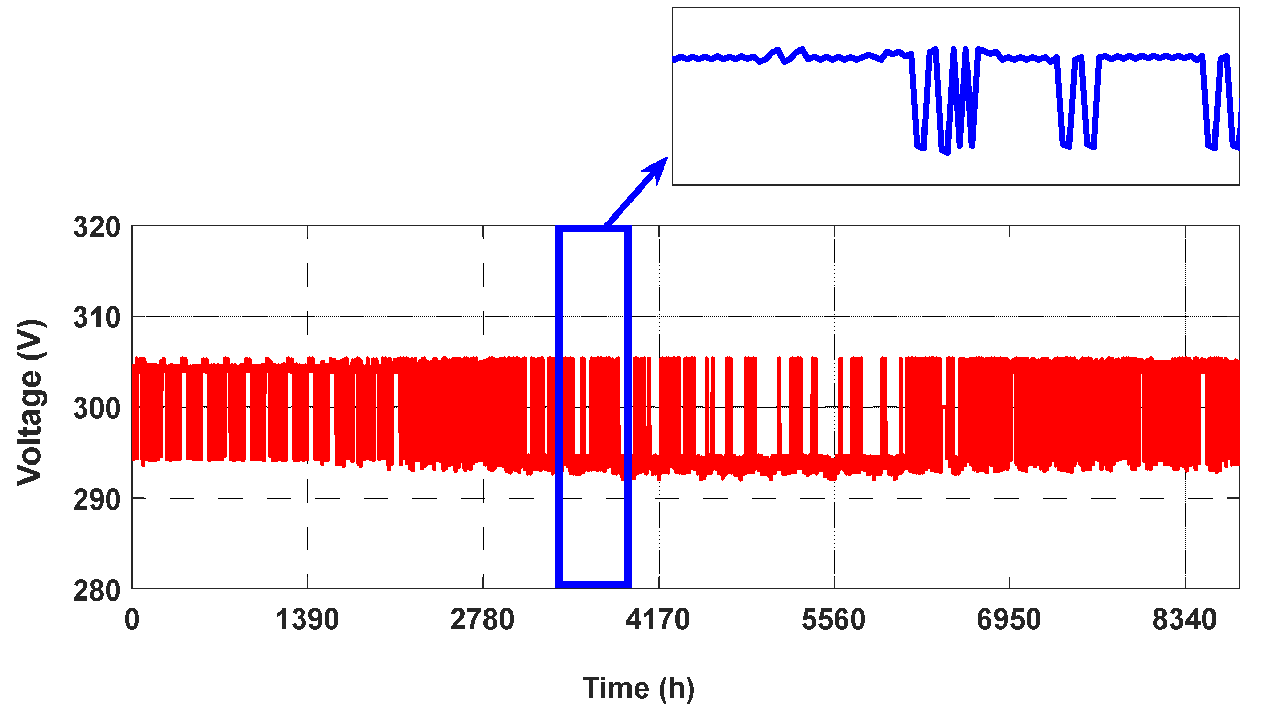
  • EVs Power Discharging Mode: In scenarios where the available power from RES is insufficient to meet the HMG load requirements, the system operates in this mode. Here, the EVs battery are utilized to regulate the output voltage through battery discharge, serving as voltage sources. The goal of the controller is to enable precise energy sharing and optimal voltage regulation within an acceptable threshold to reduce dependence on upstream power received from the AC grid.
  • Idle Power Mode: This mode signifies a state of equilibrium where the HMG system operates independently in an islanded mode, with the DFIG and PV systems being adequate to meet the demands. In this mode, EV batteries are not involved in the energy management scheme. The RES undertakes the regulation of the HMG bus voltage, utilizing fuzzy tracking control to maintain stability.
  • EVs Power Charging Mode: During times of abundance of power from RES, the supply from the DFIG and PV surpasses the connected demands, leading to an increase in energy levels. In such instances, the surplus energy is directed towards charging the EV batteries for later use, which in turn manages the HMG voltage through their charging mechanisms.
Given the three modes of operation detailed above, the following equations set the conditions for the HMG operation in this study:
P g + P P V + P D F I G P d m i n
P d m i n P g + P P V + P D F I G P d m a x
P g + P P V + P D F I G P d m a x
The dynamic behavior of the PV system is modeled through the following set of equations that govern the inductor current, the capacitor voltage, and the output voltage, as highlighted in the left part of Figure 1:
I ˙ L , P V = 1 L P V R 0 , P V I 0 , P V I L , P V R L , P V I L , P V ν 0 , P V + 1 L R E V D , P V + ν P V R M , P V , I L , P V ν 1 V D , P V L P V
ν ˙ V P = 1 C R E I V P I L , P V v 1
ν ˙ 0 , P V = 1 C 0 , P V I L , P V I 0 , P V
Equation (4) delineates the interplay between the generated current, the system’s inherent resistances, and the impact of these factors on the current through the inductor, I L , P V , a key component for energy transfer in the PV system, and the rate of change in the inductor current. R 0 , P V , R L , P V , are resistances on both the conductance and inductance sides, while V 0 , P V ,   V D , P V represents the dynamics introduced by the diode and capacitor of the grid. Equation (5) focuses on the voltage dynamics across the PV capacitor ( ν ˙ V P ), illustrating how the capacitor moderates the fluctuation in the system’s voltage, which is crucial for maintaining the stability of the voltage supplied by the PV system to ensure it meets the demand without introducing volatility into the HMG energy supply. On the other hand, Equation (6) models the output voltage ( ν ˙ 0 , P V ) dynamics of the PV system, which shows how variations in demand and supply currents affect the output voltage, ensuring the PV system’s output is stable and reliable in a hybrid microgrid.
The dynamic modeling of the DFIG machine within the HMG system, shown in Figure 1, can be described succinctly as follows, considering the generator’s power and voltage dynamics under varying operational conditions.
P r ˙ = ω s l i p ν α β , r T J T I α β , r + 1 L ν α β , r   T ν α β , r ν α β , r   T ν d c 2 L ν α β , r
Q s ˙ = ω s y n c ν α β , s T J T J I α β , s + ν α β , s T J L ν α β , s ν α β , s T J ν d c 2 L ν α β , s
ν ˙ α β , r = ω s l i p J ν α β , r
I ˙ α β , r = 1 L ν α β , r ν d c 2 L ν α β , r
ν ˙ d c = 1 C R L ν d c + I α β , r T 2 C ν α β , r
Here, Equations (7) and (8) highlight the rotor and stator’s roles in managing active and reactive power while maintaining voltage stability and power quality within the HMG. Where P r ˙ represents the rate of change in rotor power considering slip frequency ( ω s l i p ), rotor currents ( I α β , r ), and DC link voltage ( ν d c ), with Q s ˙ as the reactive power dynamics of the stator, incorporating synchronous speed ( ω s y n c ), stator currents ( I α β , s ), and their interaction with the grid voltage. On the other hand, Equation (9) demonstrates the voltage behavior in response to frequency variations, which is critical for adapting to changing load demands and operational conditions. Equation (10) models the DFIG response to external voltage variations, ensuring efficient power conversion and stability of the HMG energy supply. The dynamic behavior of EVs’ batteries could further be encapsulated by the following equations that delineate aspects of battery operation and thermal management:
I ˙ 1 , E V = 1 R 1 , E V C 1 , E V I m , E V I 1 , E V
Q ˙ e , E V = I m , E V
θ ˙ E V = 1 C θ , E V P s , E V θ E V θ a , E V R θ , E V
θ p , E V = G p , E V ν P N , E V
G p , E V = G p 0 , E V e ν P N , E V / ν P 0 , E V + A p , E V 1 θ E V / θ f , E V ,
where I ˙ 1 , E V outlines the current dynamics of the EVs battery, relating the change in current to the difference between the main and auxiliary currents through resistive and capacitive components; Q ˙ e , E V represents the rate of change in extracted charge, which is directly proportional to the main current and is a needed parameter for monitoring the state of charge (SoC) and energy usage efficiency of the EV battery. Equation (14) presents thermal modeling crucial for preventing overheating and ensuring the safety and durability of the battery, where θ ˙ E V models the temperature dynamics of the battery, factoring in the specific heat capacity ( C θ , E V ), power dissipation ( P s , E V ), ambient temperature ( θ E V ), and thermal resistance ( R θ , E V ). On the other hand, Equation (15) defines the thermal power generated within the battery, which is a function of the battery’s power coefficient ( G p , E V ) and nominal voltage. Finally, Equation (16) underscores the significance of thermal effects on battery performance and efficiency.
The HMG system’s operational efficacy relies heavily on the accurate modeling of EVs as integral energy storage components. Hence, the interplay between the charging/discharging processes of EV batteries and their impact on the grid’s stability and voltage regulation could be formulated, as follows:
I ˙ E V = 1 L E V 1 ν ν d c + 1 L E V ν E V
ν ˙ d c = 1 C 0 , E V 1 ν I E V + 1 C 0 , E V I 0 , E V ,
Equation (17) shows the influence of the inductance, duty cycle, and the DC bus voltage as well as the EV voltage on the charging and discharging process, while Equation (18) details the dynamics of the DC bus voltage in such processes, where the capacitance of the EVs battery plays a central role in managing voltage fluctuations. Hence, the charging and discharging formula could be formulated as follows:
V E V d i s = V o c K C n C n S O C S O C K C n S O C + 0.1 C n I b a t t + A e S O C · B + R i n I b a t t
V E V c h a r g = V o c + K C n C n S O C I b a t t K C n C n S O C S O C + A e S O C · B + R i n I b a t t
where the SoC value is calculated using the Coulomb counting method and corrected according to the actual battery capacity. The SoC is calculated as follows:
S O C = S O C 0 I b a t t · t C n
Considering the first operational mode, EVs Power Discharging Mode; cooperative functionality of the EVs battery, DFIG and PV units within the HMG are carefully integrated for proper system modeling, as follows:
I ˙ m , E V = 1 R 0 , E V L E V 1 ν 3 ν 0 , E V + 1 R 0 , E V L E V ν E V G ˙ p , E V ν P N , E V G p , E V ν ˙ P N , E V
I ˙ 1 , E V = 1 R 1 , E V C 1 , E V I m , E V I 1 , E V ,
ν ˙ 0 , E V = 1 C 0 , E V 1 ν 3 I m , E V I p , E V 1 R 0 , E V C 0 , E V I 0 , E V
P r ˙ = ω s l i p ν α β , r T J T I α β , r + ν α β , r T ν α β , r L r ν α β , r T ν 0 , g 2 L r ν α β , r
Q s ˙ = ω s y n c ν α β , s T J T J I α β , s + ν α β , s T J ν α β , s L s ν α β , s T J ν 0 , g 2 L s ν α β , s
ν ˙ α β , r = ω J ν α β , r
I ˙ α β , r = ν α β L r ν 0 , g ν α β , r 2 L r
ν ˙ 0 , g = 1 C R L g ν 0 , g + ( I α β , r T + I α β , s T ) 2 C L g ν α β , s
I ˙ L , P V = 1 L R E R 0 , P V I 0 , P V I L , P V R L , P V I L , P V ν 0 , P V + 1 L R E V D , P V + ν P V R M , P V , I L , P V ν 1 V D , P V L P V
ν ˙ P V = 1 C P V I P V I L , P V v 1
ν ˙ 0 , P V = 1 C 0 , P V I L , P V I 0 , P V
Here, Equation (22) models the dynamics of the EV battery’s main current influenced by the boost converter’s operation, including efficiency losses ( G ˙ p , E V ) and the variation of charges ( ν P N , E V ). Equations (23) and (24) describe the adjustment in output current and voltage based on recorded current flows in the system, which is essential for maintaining optimal battery operation and preventing any unnecessary over-discharging. Simultaneously, Equations (25)–(29) model the DFIG system’s performance, capturing slip-based power generation and reactive power dynamics with respect to the rotor and stator interactions. These equations highlight the DFIG’s capability to adapt its output based on the grid’s demand, including the adjustment of rotor current ( I α β , r ) and grid voltage ( ν 0 , g ) to ensure stability and efficient energy conversion. The PV system’s contribution is elucidated through Equations (30)–(32), which details the current and voltage dynamics in the presence of a buck converter, which emphasize the PVs role in sustaining the microgrid’s energy supply, particularly by adjusting the output voltage and managing the load current to align with the system’s energy requirements. Hence, the voltage level that could be supported by the HMG during discharging mode could be reformulated as follows:
ν 0 , E V = I 0 , E V R E V + I 0 , E V + I 0 , g + I 0 , P V R L
ν 0 , g = I 0 , g R g + I 0 , E V + I 0 , g + I 0 , P V R L
ν 0 , P V = I 0 , P V R P V + I 0 , E V + I 0 , g + I 0 , P V R L
where the R E V , R g , R P V , R L are the circuit resistances of the EVs battery, DFIG system, PV system, and load demand. Now, focusing on optimizing the PV performance, the Maximum Power Point Tracking (MPPT) of the PV shown in Figure 1 could be given as:
0 = I P V n p γ I r s ν * e γ ν *
While the dynamics of the wind turbines in the DFIG could be given from:
P w = 1 2 C p ( λ , β ) ρ a A v 3
C p ( λ , β ) = 1 2 r C f λ 0.022 β 2 e 0.255 r C f λ
P w a v t = 0 ,                                                       i f   v < v l 1 2 C p λ , β ρ a A v 3 t             i f   v l v < v r                 P w a v                                                   i f       v r v < v u 0                                                   i f   v > v u
Here, Equation (36) highlights the MPPT mechanism for the PV systems, employing an exponential function to dynamically adjust to changing solar irradiance levels, thereby ensuring the PV system operates at its optimum power output. For wind energy conversion, Equations (37) through (38) provide a comprehensive model. Equation (37) outlines the maximum extractable power from wind as a function of air density ( ρ a ), turbine blade area (A), and wind velocity ( v 3 ), modulated by the power coefficient ( C p), which is further detailed in Equation (38). This coefficient, dependent on the tip speed ratio (λ) and blade pitch angle (β), indicates the efficiency with which a wind turbine converts kinetic wind energy into electrical power. The piecewise function in Equation (39) delineates the average power output across different wind speed ranges.
To carefully underscore the roles of the EVs battery, DFIG, and PV systems within the broader framework, further refinement is needed towards optimizing the operational efficiency of the discharging process. Hence, to further optimize the EVs battery discharge characteristics and its impact on the HMGs stability, particularly in the face of fluctuating load demands, Equations (22)–(24) can be reformulated as follows:
I ˙ m , E V = 1 R 0 , E V L E V I 0 , E V R E V + I 0 , E V + I 0 , g + I 0 , R E R L + ν 0 , E V R 0 , E V L E V ν 3 + 1 R 0 , E V L E V ν E V G ˙ p , E V ν P N , E V G p , E V ν ˙ P N , E V
I ˙ 1 , E V = 1 R 1 , E V C 1 , E V I m , E V I 1 , E V
ν ˙ e , E V = 1 C 0 , E V 1 ν 3 I m , E V + I p , E V ν e , E V + ν r e f I 0 , g + I 0 , P V R L R 0 , E V C 0 , E V R E V + R L
Additionally, to account for the complexities of wind energy conversion and its integration into the HMG, ensuring that the system’s energy supply remains responsive to varying wind speeds while maintaining voltage stability, Equations (25)–(29) can be reformulated as follows:
P ˙ e = ω ν α β T J T I α β + 1 L ν α β   T ν α β ν α β   T ν 0 , g 2 L ν α β
Q ˙ e = ω ν α β T J T J I α β + ν α β T J L ν α β ν α β T J ν 0 , g 2 L ν α β
ν ˙ 0 , g = 1 C R L ν e , g + I α β T 2 C ν α β 1 C R L ν r e f
v ˙ e , D F I G = v 0 , D F I G v r e f
v ˙ e , P V = v 0 , P V v r e f
ν ˙ α β = ω J ν α β
I ˙ α β = 1 L ν α β ν 0 , g 2 L ν α β
ν ˙ 0 , g = 1 C R L ν e , g + I α β T 2 C ν α β 1 C R L ν r e f
Similarly, the PV system’s contribution, initially outlined in Equations (30)–(32), is revisited to offer a more detailed perspective on the solar irradiance’s impact on power output, as follows:
e ˙ P V = 1 C P V I P V + I L , P V v 1
I ˙ L , P V = R 0 , P V L P V I 0 , R E R 0 , P V L P V 1 + R L , P V I L , P V R 0 , P V L P V I 0 , P V R P V R 0 , P V L P V I 0 , E V + I 0 , g + I 0 , P V R L + 1 L P V V D , P V + ν P V R M , P V I L , P V u 1 V D , P V L P V
v ˙ e , P V = 1 C 0 . P V I L , P V I 0 , P V
Now, considering the Idle Power Mode highlighted by Equation (2), where power is only supplied from PV and DFIG, as follows:
ν 0 , g = I 0 , g R g + I 0 , g I 0 , P V R L ,
ν 0 , P V = I 0 , R E R P V + I 0 , g I 0 , P V R L
Hence, the dynamic operation of the HMG with the absence of EVs battery discharging is given as follows:
ν ˙ e , g = R g I 0 , g + R L I 0 , g + R L I 0 , R E C R L + I α β T 2 C ν α β
ν ˙ P V = 1 C P V I P V I L , P V v 1
I ˙ L , P V = R 0 , P V L P V 1 R P V R L I 0 , P V 1 + R L , P V I L , P V R L I 0 , g + 1 L R E V D , P V + ν P V R M , P V ν 1 V D , P V L P V
ν ˙ 0 , P V = 1 C 0 , P V I L , P V I 0 , P V
Here, Equation (56) models the dynamics of grid voltage, emphasizing the regulation based solely on the contributions from the DFIG and PV systems. Unlike in the discharging mode, where the EV battery’s involvement is prominent, this equation adapts to the absence of battery support, focusing on mitigating voltage fluctuations through the real-time outputs from RES. Similarly, Equations (57) and (58) provide the PV system’s operational nuances, with (57) detailing the voltage dynamics across the PV array and (58) describing the current flow dynamics within the PV circuit. On the other hand, Equation (59) provides insight into the overall voltage management at the PV output, aiming for seamless integration into the grid. This equation, alongside (57) and (58), underscores the critical role of the PV system in maintaining energy supply and grid stability during the floating power mode, highlighting the strategic shift from energy storage reliance to maximizing renewable generation capabilities in this mode.
Moving to the third operational mode, the EVs battery charging mode, the energy management strategy of the HMG undergoes a significant transition through prioritizing the charging of batteries. This mode distinguishes itself from the earlier modes—discharging and idle power modes—by its focus on utilizing excess power for battery charging, thereby ensuring energy storage for future use or grid support. The EVs battery model is then reformulated as follows:
I ˙ 1 , E V = 1 R 1 , E V C 1 , E V I m , E V I 1 , E V
I ˙ m , E V = 1 R 0 , E V C 0 , E V I L , E V I m , E V ν ˙ P N , E V R 0 , E V
I ˙ L , E V = 1 L E V R 0 , E V I m , E V I L , E V R L , E V I L , E V I m , E V R 0 , E V + ν P N , E V + 1 L E V V D , E V + ν 0 , g R M , E V ν 2 V D , E V L E V
Equations (60) and (61) detail the charging dynamics, capturing the interplay between the charging current’s inflow and outflow through the resistive and capacitive elements of the EV’s battery circuit. Unlike the discharging mode, these equations emphasize reversing the current flow to replenish the battery’s stored energy. Additionally, Equation (62) further refines the battery charging model by accounting for the complex interactions within the EV charging circuit, including the effects of inductance, resistance, and the induced voltage from RES. This equation ensures optimal charging efficiency by modulating the charging current in response to RES dynamics, given as follows:
I 0 , g = I 0 , E V + ν 0 , g I 0 , g R g R L
I ˙ 1 , E V = 1 R 1 , E V C 1 , E V I m , E V 1 R 1 , E V C 1 , E V I 1 , E V
I ˙ L , E V = 1 L E V R 0 , E V I m , E V I L , E V R L , E V I L , E V I m , E V R 0 , E V + ν P N , E V + 1 L E V V D , E V + ν 0 , g R M , E V ν 2 V D , E V L E V
ν ˙ e , g = 1 C R L ν e , g + I α β T 2 C ν α β 1 C R L ν r e f
I ˙ L , P V = 1 L R E R 0 , P V I 0 , P V I L , P V R L , P V I L , P V ν 0 , P V + 1 L R E V D , P V + ν P V R M , P V ν 1 V D , P V L P V
Equations (63) through (67) provide a mathematical description of the contributions of the DFIG, and PV systems during the charging phase. These equations, while mirroring the operational dynamics of previous modes, are now reoriented towards maximizing energy capture and storage. Particularly, Equation (66) highlights the grid voltage regulation facilitated by the DFIG and PV outputs, ensuring stable and efficient charging of the EV batteries.
This study introduces, in the next section, the design and deployment of an intelligent, variable-fed, Type-2 Fuzzy-Logic Controller (FLC) based on the Mamdani fuzzy inference system to optimize the operation of HMGs considering the abovementioned three modes of operation. The control strategy intricately links the uncertainty of the PV outputs, the performance of the DFIG, and the SoC of the EVs battery, as follows:
ν P V ν *
  P P *
Q Q *
ν 0 , g ν r e f
ν 0 , E V ν r e f
ν 0 , P V ν r e f  
e P V = ν P V ν *
P e = P P *
Q e = Q Q *
ν e , g = ν 0 , g ν r e f
ν e , E V = ν 0 , E V ν r e f
ν e , P V = ν 0 , P V ν r e f
ν e , D F I G = ν 0 , D F I G ν r e f
Equations (68) through (73) establish the foundational objectives of the proposed controller, setting the desired operational states for the PV system, active power and reactive power, voltage levels across the grid, as well as the EVs battery and PV system, all in accordance with their respective reference values ( ν r e f ) . These targets underscore the critical balance the controller aims to achieve, ensuring that each component of the HMG operates at its optimum level for efficiency and stability. To accurately monitor and adjust the system’s dynamics, the controller utilizes a set of error variables, highlighted in Equations (74)–(79). These variables represent the deviation of the current state from the desired reference points. By quantifying these discrepancies, the proposed IT2FLC can apply corrective measures to minimize these errors, thereby aligning the HMG’s operation with the set objectives. Lastly, Equations (74)–(80) not only facilitate precise control over the microgrid’s components but also illustrate the comprehensive scope of the controller’s regulatory capacity. Through the adaptive adjustment of the PV system’s voltage, the active and reactive power outputs, and the voltage levels across the grid and EVs battery, the controller ensures that the HMG maintains a stable and efficient energy supply. Additionally, by addressing the specific needs of the DFIG, the controller enhances the integration of wind energy into the HMG, further contributing to sustainable operation.

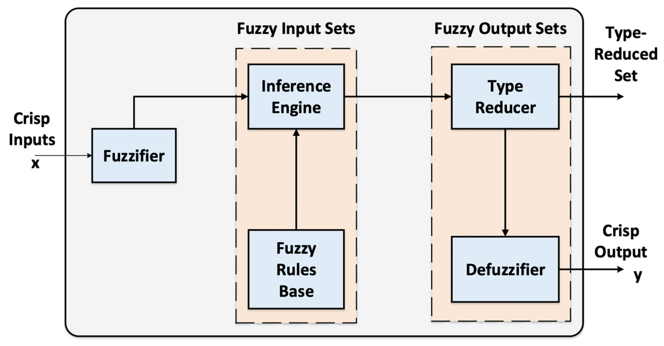
2.2. Design of Intelligent, Variable-Fed, Type-2 FLC for HMG Energy Management

In fuzzy logic systems, the challenge of addressing numerical and linguistic uncertainties that lead to rule ambiguities is pivotal. Hence, Type-2 FLC provides an advanced solution for managing these uncertainties. Unlike Type-1 systems, Type-2 FLC distinguishes itself through its unique handling of membership functions (MFs) and output processing mechanisms. Illustrated in Figure 2, the architecture of the proposed IT2FLC includes the following essential components: a fuzzifier, an inference engine, a fuzzy rule base, and an output processor that integrates both a type-reducer and a defuzzifier.
Leveraging the extensive mathematical modeling outlined in Section 2.1, the proposed IT2FLC is particularly effective in this kind of problem, as it introduces a higher degree of flexibility in handling uncertain inputs and rules, crucial for the adaptive energy management of HMGs. The fuzzifier component of IT2FLC transforms crisp inputs into interval Type-2 fuzzy sets with fuzzy boundaries for MFs, enabling a better representation of input uncertainties. This is critical in scenarios where precise mapping of MFs is hindered by incomplete information or system anomalies. Below is a description of each of the components shown in Figure 2:
(a)
Fuzzifier: the fuzzifier in the IT2FLC transforms crisp input vectors, ( x 1 ,   x 2 ,   . . . ,   x n ) T , into interval type-2 fuzzy sets, fundamentally differing from Type-1 fuzzy logic systems, which employ membership functions defined by precise numbers. In T2FLC, membership functions are characterized by a range of values within [0, 1], reflecting the inherent fuzziness and allowing for the representation of uncertainty directly within the function itself. This characteristic is particularly advantageous in scenarios where system faults or incomplete data compromise the accuracy of membership function mapping. By accommodating uncertainties in input variables, IT2FLC enhances the model’s robustness, making it an effective tool for managing complex systems such as HMGs.
(b)
Fuzzy-rule Base: the fuzzy rules within IT2FLC are formulated as linguistic If-Then, statements, comprising multiple antecedents linked to a singular consequent. These rules establish a Type-2 fuzzy relationship among n inputs within the input space and a single output, serving as the foundation for decision-making within the system. The kth rules of Type-2 FLC can be formulated as follows [39]:
i f   x 1 = F 1 k ,   x 2 = F 2 , k . . . ,   x n = F n k
Then, for k = 1,2 , . . , N ;
Y k = G k
Here, F i k   represents the IT2FLC of input state i of the kth rules, while xs resemble the inputs, G k as outputs of the IT2FLC of the N rules.
(c)
Fuzzy-inference Engine: The fuzzy inference engine serves the crucial function of amalgamating fuzzy rules to transform fuzzy inputs into corresponding fuzzy outputs. This input-to-output conversion lays the groundwork for discerning patterns or making informed decisions. Within the engine, a comprehensive database of MFs, along with the defined fuzzy If-Then rules and logical operations, facilitates the systematic evaluation of inputs. The engine executes calculations that include the intersection of antecedents, the aggregation of rule consequents through union operations, and the execution of the extended sup-star composition. In the framework of IT2FLC, each activated (or triggered) rule, denoted as the kth rule, delineates an interval bound by two extremities [40,41]. This range is critical for encapsulating the inherent uncertainties and facilitating a more adaptable output generation. This interval-based approach enriches the system’s capability to navigate through the dynamic and uncertain nature of inputs, as follows:
F k x 1 ,   x 2 ,   . . . ,   x n = f   k x 1 , x 2   . . . ,   x n , f ¯ k x 1 , x 2   . . . ,   x n = f   k , f ¯ k
where f   k and f ¯ k are found as follows:
f _ k = u _ F 1 k ( x 1 ) . u _ F 2 k ( x 2 ) . . . . u _ F n k ( x n )
f ¯ k = u ¯ F 1 k ( x 1 ) . u ¯ F 2 k ( x 2 ) . . . . u ¯ F n k ( x n )
(d)
Type-reducer: Type reduction is tasked with transitioning the Type-2 fuzzy set output into a Type-1 fuzzy one. This step is critical, as it bridges the computational gap between high-dimensional fuzzy logic and the actionable, crisp outputs necessary for real-time energy management decisions for the HMG. Following type reduction, the defuzzification phase further processes the Type-1 fuzzy set, distilling it into a precise, crisp value conducive to practical application. In the context of this study, centroid-type reduction is employed for its efficacy in negotiating the intricate balance between the detailed representation of uncertainty in Type-2 sets and the requisite clarity of Type-1 sets. The centroid, A ¯ , calculation for a Type-2 fuzzy system embodies a meticulous aggregation of the system’s outputs, thereby providing a comprehensive yet concise representation of the fuzzy logic’s inference outcome, as follows:
G C A ¯ = l 1 L 1 l n L n w 1 W 1 w n W n T i = 1 n u l ( l i ) T i = 1 n u w ( w i ) i = 1 n   l i . w i i = 1 n   w i
Here, G C A ¯ represents the Type-1 reduced set, with n as total number of discrete points of A ¯ , l i R and w i   [0, 1], while u l ( l i ) and u w ( w i ) are membership functions of l i and w i , with T is defined as a t-norm. Similarly, Equation (86) can be expressed as the centroid for the proposed IT2FLC as follows:
G C A ¯ = y z x ,   y r x = y 1 [ y z 1 , y z r ] y N [ y z N , y z N ] f 1 [ f   1 , f ¯ 1 ] f N [ f   N , f ¯ N ] i = 1 N   f i . y i i = 1 N   f i
(e)
Defuzzifer: The predominant method employed for defuzzification involves calculating the centroid of the type-reduced set, a process that ensures the final decision or output retains a balance between the understanding captured by the fuzzy logic and the actionable clarity required for effective control. To achieve this balance, the following expression calculates the centroid of an n-point discretized type-reduced set:
y ( x ) = i = 1 n y i . u ( y i ) / i = 1 n     u y i
With the iterative Karnik–Mendel technique is utilized to compute the output. Therefore, the defuzzified output of the IT2FLC is:
y o u t p u t ( x ) = y z + y r 2
With
y z ( x ) = i = 1 N   f z i . y z i i = 1 N   f z i
y r ( x ) = i = 1 N   f r i . y r i i = 1 N   f r i
where y i represents the points in the discretized set, and u denotes their associated membership values. This formula encapsulates the essence of defuzzification within the proposed IT2FLC, highlighting its capability to facilitate the transition from fuzzy to crisp logic. Through this precise mathematical operation, the IT2FLC efficiently converges on a single output value that is both reflective of the complex inputs and suitable for direct application within the HMG management context.

3. Case Study and Results

3.1. Description of the Developed Hybrid Microgrid Simulink Model

To validate the mathematical concept described in this work, a Simulink-based model of a hybrid microgrid energy system is developed, as seen in Figure 3. The model is segmented into distinct modules, each modeling a component of the microgrid. The RES block simulates energy generation from a 5 kW PV and a 3 kW DFIG, utilizing environmental data inputs such as irradiance and wind speed. An EV battery model is integrated to simulate the interactive influence of the battery’s SoC on the energy management of the HMG. To ensure a feedback-oriented approach, the measurements block captures real-time data on system variables, including power outputs and SOC, providing critical feedback to the IT2FLC block for continuous optimization. The utility grid and load profile blocks represent the HMG’s interaction with the main AC power grid and demand side, respectively, showcasing the system’s response to fluctuating consumption patterns.
The Simulink model closely mirrors the actual HMG environment by incorporating PV systems, DFIG, and EVs, and utilizing real-world data for wind, solar irradiance, and load demands. However, it simplifies environmental complexities, sensor inaccuracies, and communication delays that are inherent in real-world scenarios, which may be overcome by integrating Hardware-in-the-Loop (HIL) to conduct similar studies.

3.2. Input Parameters

In this study, the simulation is supported by a detailed representation of realistic input data for PV cells, characteristics of EV batteries, and wind energy components. For the PV cell simulation, key parameters include a maximum power output of 5000 Watts, achieved at a maximum power point voltage of 42.48 Volts, and a current of 5.88 Amperes. The cells demonstrate an open-circuit voltage of 51 Volts and a short-circuit current of 6.3 Amperes, structured in an array comprising 72 cells in series and a single cell in parallel configuration. The standard reference conditions for these simulations are set at a temperature of 25 degrees Celsius and solar irradiance of 1000 Watts per square meter, with an ideality factor adjusted to 0.945. On the other hand, the EVs battery model is tailored to reflect the dynamics of Lithium-Ion batteries, with the discharge and charge phases both designed around a maximum capacity of 100 Ampere-hours and a steadfast open-circuit voltage of 12 Volts. The internal resistance remains constant at 0.0012 Ohms for both phases. The charge and discharge characteristics are further defined by specific parameters: during discharge, ‘K’ is set at 0.00040 Volts, ‘A’ at 1.9896 Ohms, and ‘B’ at −9 Ah−1, while the charging phase sees ‘K’ adjusted to −0.074739 Volts, ‘A’ to 0.0015 Ohms, and ‘B’ to 6 Ah−1, reflecting the intricate behaviors of battery operations under varying conditions. Finally, wind energy input parameters encompass a maximum power output of 3000 Watts, with a lambda (tip speed ratio) of 8.1 and a beta (blade pitch angle) of 0, ensuring optimal aerodynamic efficiency. The turbine’s blade spans an area of 8 square meters, operating within an air density (Pa) of 1.2 kg per cubic meter. The system is designed to initiate generation at a cut-in speed of 5 m per second, reach its rated performance at 12 m per second, and cease operation at a cut-off speed of 20 m per second, encapsulating the variable nature of wind availability. Moreover, this study utilizes real-world input data spanning over a year of solar irradiance [42], wind speed [43], and residential demand patterns [44]. This approach ensures that the analysis and outcomes are grounded in the practical, operational conditions of HMG systems.

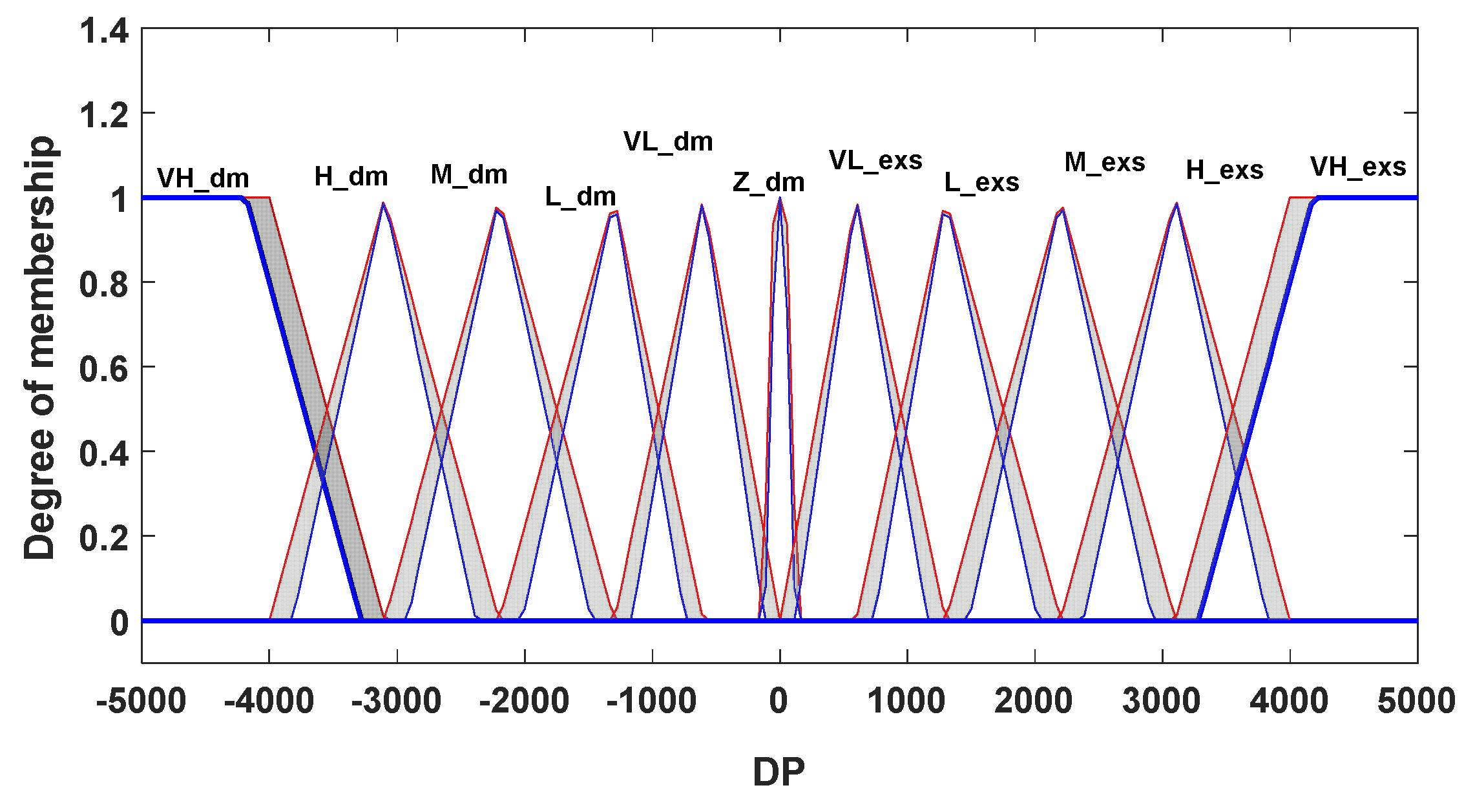
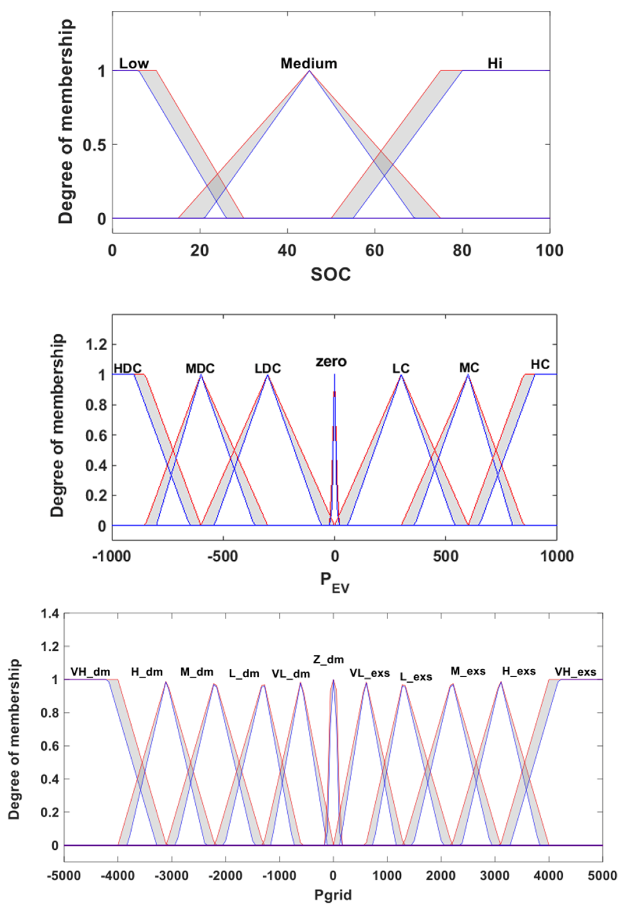
3.3. Fuzzification of the Input

In the design of the proposed variable-fed IT2FLC for HMG energy management, the fuzzification process is central as it transforms quantifiable inputs, specifically the net power from RESs versus the load demand and the SOC of the EVs, into fuzzy sets. As illustrated in Figure 4, this study employs an array of both triangular and trapezoidal membership functions. These functions are strategically chosen to span the complete spectrum of input power variances, thereby providing the proposed controller with a wide dataset for robust decision-making. This process ensures that the controller accurately gauges the degree of consistency of the input power differential within each function’s scope, subsequently leveraging this information to initiate appropriate control actions.
The fuzzification of the SOC variable transforms discrete SOC values into a continuum of fuzzy values. MFs are designed to capture the extent of alignment between the SOC’s numerical value and corresponding linguistic terms. In this framework, a combination of triangular and trapezoidal MFs is adopted to accurately represent the SOC input, which is particularly important for the variable’s nonlinear characteristics. These functions are devised to cover the entire operational range of SOC, from 20% to 90%. Each function is calibrated to reflect a specific operational state—‘Low,’ ‘Medium,’ or ‘High’—thus encapsulating the entire spectrum of charging states. This ensures that each linguistic label is backed by a quantitative model that mirrors the real-world behavior of the SOC, providing a robust basis for the subsequent inferential processes within the HMG framework. Figure 5 shows the fuzzification membership plots for, from top-to-bottom: SoC of EVs, output power of the EVs battery, and output power of the HMG level.

3.4. Fuzzy Rule Base

The fuzzy rule base serves as the cornerstone of the Fuzzy controller, encapsulating expert knowledge through a collection of conditional statements. Each “if-then” rule elucidates the intricate relationship between input variables—such as power discrepancies, state of charge, and demand fluctuations—and the controller’s outputs, which are instrumental in dictating the HMGs behavior for each operational mode. In this study, a comprehensively unique set of 33 fuzzy rules, shown in Table 1, has been developed to encapsulate the full spectrum of potential operational dynamics. This extensive rule base is determined through rigorous simulation testing, encompassing a multitude of scenarios reflective of the HMG’s operational environment.

3.5. Case Study Incorporating Dynamic HMG Operation

The comprehensive simulations that cover a span of a year of HMG operation offer an empirical basis for evaluating its operational dynamics under varying conditions and the efficacy of the proposed intelligent Type-2 Fuzzy Logic Controller (IT2FLC). Data comprising hourly variations in wind, solar irradiance, and load demands form the core inputs, facilitating a robust analysis that reflects real-world scenarios. Figure 6 provides a graphical representation of the PV power output, which distinctly fluctuates with seasonal changes in solar irradiance. This variation is critical for assessing the proposed IT2FLC’s capability in managing the energy balance within the HMG. Particularly noteworthy is the adaptability of the system during the solar peak times and the diminished outputs during the winter months, illustrating the control enabled by the proposed controller. A more detailed view, presented in a zoomed-in section of Figure 6, reveals the PV output for a select four-day period, highlighting the proposed controller precision in short-term energy prediction and allocation. On the other hand, Figure 7 shows the output power from the DFIG for a one-year simulation, showing the clear variations across different seasons.
Figure 8 showcases the load profile pertinent to the study, with a maximum and minimum load of 2295 W and 1196 W, respectively. This profile, illustrating the consumption behavior typical of a residential entity over an annual period, is instrumental for the HMGs energy management concept. The methodological approach to deriving this profile involved comprehensive monitoring of residential energy use, aggregating, and averaging the data to establish an hourly representation of load across the year. This pattern, which is inherently cyclical, mirrors the variability inherent in residential energy consumptions. Crucially, this load profile serves as a foundational parameter within the HMG control framework, as it influences the strategic decisions concerning energy allocation and distribution across the microgrid’s components, aiming to maintain an optimal balance between supply and demand. Through precise control and management based on the detailed load profile, the proposed IT2FLC’s ensure the HMG operates with heightened efficiency and stability, effectively balancing the dynamic energy demands of the residential load with the available supply from various energy sources within the microgrid.
To evaluate the performance of the proposed IT2FLC, a comprehensive series of simulations was conducted. These simulations were carefully designed to assess the HMG’s operational efficiency over a yearly cycle, with each simulation step precisely calibrated to a one-hour interval. At each of these intervals, the HMG engaged in a systematic process of data intake, analysis, and computation of control strategies, culminating in the calculation of operational setpoints for both the EV battery and the utility grid. Figure 9 and Figure 10 clearly show the efficacy of the proposed controller in achieving optimal energy management considering the dynamic nature and uncertainty evolving in the operation of the HMG, where they show the powerset points for the utility grid and EVs battery as modulated by the controller. These results underscore the system’s adeptness at managing energy flows within the HMG, aligning energy utilization with the operational requirements of EVs across the three considered modes.
Throughout the year, all three modes of operation are actively engaged by the controller to optimize energy flow within the HMG, as shown in Figure 9 and Figure 10. The experimental results highlight several advantages of the proposed IT2FLC. Its ability to adaptively manage energy flows ensures that the system can respond to dynamic and uncertain conditions effectively. For instance, the controller’s performance during peak demand hours (as seen from the extensive utilization of EVs discharging power mode) demonstrates its capability to enhance grid support and energy reliability. Additionally, the seamless transition between different modes of operation (discharging, idle, and charging) further underscores the controller’s flexibility in maintaining optimal energy balance within the HMG components. However, it is particularly noteworthy that the EVs discharging power mode (Mode 1) is extensively utilized during the hot months (from the first week of May until the third week of September, as highlighted in Figure 9) to address peak demand hours, as vividly illustrated in the 24-h zoom snapshot. This period is characterized by significant energy being provided to the grid, demonstrating the proposed controller’s strategic deployment of EV battery resources to enhance grid support and energy reliability during times of high demand. Conversely, during the colder months, a more equitable balance is observed between the EVs discharging power Mode (Mode 1) and the charging mode (Mode 3). This allows for the EVs to be charged during mid-day hours when energy is abundant and to discharge during the second peak to off-peak hours in a cooperative and balanced manner. This shift in operational dynamics ensures an efficient use of stored energy, optimizing the HMG’s performance, and contributing to a more sustainable and economic operation. Through the adept management of EV battery interactions—leveraging discharging capacities during times of surplus and modulating charging activities in response to the inherent balance between energy availability and demand—the proposed intelligent IT2FLC demonstrates a sophisticated approach to optimizing energy flows considering the stochastic nature of the input variables. This ensures not only the maintenance of energy supply during critical demand peaks but also the effective utilization of EVs as dynamic components within the HMG, fostering an enhanced balance between energy supply, demand, and storage efficiency across varying seasonal demands. However, the implementation of IT2FLC also presents certain limitations. One potential challenge is the computational complexity associated with real-time processing of fuzzy logic rules, especially when handling large datasets and multiple variables. This could impact the system’s response time in rapidly changing conditions. Furthermore, the reliability of the controller depends on the accuracy of the input data (e.g., solar irradiance, wind speeds, and load demands). Inaccurate or delayed data could lead to suboptimal decision-making, affecting the overall efficiency of the HMG.
Figure 11 shows the SoC through the year for the EVs battery. The red bars indicate the charging and discharging cycles of the EVs batteries over time. A positive red bar indicates EV in charging cycle, leading up to a higher SoC, while a negative in the red bar indicates a discharging cycle where the EV is being used or is providing power back to the grid or home. As shown in the figure, the SoC fluctuates significantly, primarily due to its daily usage patterns or controlled charging/discharging by the proposed IT2FLC. Moreover, the zoomed-in snapshot shows the SoC changes during peak hours of a specific day in June. The larger fluctuations in SoC within this inset is due periods of significant discharging (when energy is taken from the EVs battery, which would show as a decrease in SoC) and charging (when energy is put into the battery, increasing the SoC).
The voltage profile of the HMG across the year is presented Figure 12. In the warmer months, the plot exhibits noticeable variances indicative of the EVs discharging mode during peak hours to support the HMGs operation. This is observable as voltage sags followed by recoveries, marking periods where EVs discharge, contributing positively to the grid during peak demand. The zoomed-in snapshot offers a view of this activity, underscoring the strategic timing of discharging during high-demand intervals to stabilize the grid. As the seasons transition towards colder months, the results suggest a harmonious oscillation between the discharging and charging of EVs—Modes 1 and 3, respectively. During these times, a surplus of energy during mid-day prompts the charging of EVs, while the descent into evening peak and off-peak hours triggers a discharge from the EVs. This cyclic pattern is indicative of a well-balanced and cooperative energy management approach, moderating the voltage within a tighter band, thereby implying a consistent and stable grid operation under the supervision of the proposed controller.
Table 2 provides a comprehensive overview of the energy exchange dynamics between the HMG and the utility grid over the monitoring period. As seen in Table 2, the study reveals that the HMG was a net recipient of energy from the utility grid for a duration of 4611 h. During this interval, the HMG consumed an average power of 8009.5 kW, aggregating to a total energy import of 18,759 MWh. Conversely, the microgrid supplied energy back to the utility grid for a lesser span of 3647 h at an average export power of 5408.4 kW, culminating in a substantial energy export totality of 31,178 MWh. The net energy balance underscores that the HMG imported 12,467 MWh from the utility grid. From an economic perspective, with the assumed utility cost of $0.27 per kWh, the microgrid’s net energy transactions resulted in a significant cost avoidance of $3,748,900, money that would have otherwise been an expenditure for energy procured from the grid. In comparison, the classical FLCs yielded cumulative financial savings of −3,030,638.64 USD. This demonstrates that the proposed IT2FLC offers a 23.7% improvement in cost savings, further validating its superior performance. The table also details the energy management within the HMG, considering the integrated EVs’ batteries. The EVs were engaged in charging operations for 365 h, absorbing power at an average rate of 152.22 kW and totaling an energy intake of 53.53 MWh. Battery discharging occurred over 339 h, delivering power at an average rate of 142.22 kW and contributing an energy output of 46.79 MWh to the microgrid. These figures represent the critical role of the EV battery in the HMG energy schema, balancing charge and discharge cycles to optimize grid interactions and economic benefits. Overall, the proposed IT2FLC demonstrates significant potential for enhancing the resilience and economic feasibility of hybrid microgrids. Its advanced handling of uncertainties and ability to efficiently manage diverse energy sources and loads make it a promising solution for modern energy systems. While the controller’s complexity and dependency on accurate data present certain challenges, the benefits it offers in terms of flexibility, adaptability, and optimized energy management are substantial. Future work could focus on streamlining the computational aspects and enhancing data integration methods to further improve the controller’s practical applicability.

4. Conclusions

In conclusion, this research presents a comprehensive mathematical modeling framework for hybrid microgrids (HMGs) that accounts for detailed parameters influencing the grid’s operation while considering various operational modes of EV integration. The transitions between these modes are based on real-time measurements of power supply and demand within the HMG, ensuring responsive and adaptive energy management. The proposed intelligent Type-2 Fuzzy Logic Controller (IT2FLC) continuously monitors these parameters and optimally switches between modes to maintain energy management and system stability. The models, derived and elucidated through rigorous mathematical formulations, robustly capture the dynamic behavior and un-certainty of HMGs, including PV systems, DFIG units, and the critical operational characteristics of EV batteries, particularly in their dual role as energy consumers and storage devices.
The implementation of the proposed variable-fed IT2FLC, based on Mamdani fuzzy inference, advances the management of the complex interplay of HMG components under fluctuating energy conditions. Extensive simulations validate the efficacy of the proposed IT2FLC, capturing seasonal variabilities and day-to-day energy exchange intricacies. Results indicate that the HMG, under the supervision of the intelligent controller, adeptly navigates across various modes of EV integration with the grid. This adaptability ensures efficient energy flow, harnessing renewable generation while maintaining grid stability and energy availability during peak demand periods.
The main findings from the results demonstrate the superior performance of the IT2FLC in managing energy flows within the HMG. The controller effectively mitigates the volatility of renewable energy sources by dynamically adjusting the operation of EV batteries. During high demand periods, the EVs discharge to support the grid, significantly reducing the reliance on external power sources and improving grid stability. Conversely, in periods of surplus energy, the controller efficiently directs excess power to charge the EV batteries, preparing them for future use. The simulation results highlight a well-balanced energy distribution, optimal voltage stability, and significant cost savings, emphasizing the economic and operational benefits of the IT2FLC.
Alongside the energy transaction summaries provided in Table 2, the results also reflect the strategic effectiveness of the proposed IT2FLC in managing energy surplus and deficit scenarios. By effectively utilizing the discharging capacity of EVs during high energy demand periods and leveraging their charging potential during excess power availability, the HMG sustains an optimal energy balance. This not only reinforces the grid’s reliability but also underscores a sustainable and economically viable energy ecosystem, as evidenced by the substantial cost savings highlighted. The controller’s effectiveness in maintaining voltage stability and managing the SoC of EVs, particularly under varying load conditions, is commendable. Overall, by harnessing the potential of RES, optimizing energy storage via EV batteries, and ensuring seamless integration with existing grid frameworks, the proposed controller proves to be an effective tool for providing optimal energy management solutions.
For future studies, the potential of intelligent FLCs in cybersecurity applications for energy systems is a promising avenue. As cyberattacks against energy infrastructures have significantly increased in recent years to advance political, social, or financial agendas, the cybersecurity of energy systems has become a central topic in research recently [45,46]. Intelligent FLCs can be leveraged to enhance the security of energy infrastructures against cyber threats such as Distributed Denial of Service (DDoS) attacks, a form of cyber threat that can successfully paralyze charging stations [47]. For instance, intelligent FLCs can monitor and respond to abnormal traffic patterns indicative of a DDoS attack targeting EV charging stations, thereby protecting the grid from disruptions. This integration of cybersecurity measures within an intelligent FLC framework could ensure that energy systems remain resilient to both physical and cyber threats, providing a robust defense mechanism in increasingly interconnected energy networks. Other recommendations for future studies include exploring the integration of artificial intelligence and machine learning techniques to further enhance the predictive capabilities and decision-making processes of intelligent FLCs [48,49]. Additionally, investigating the scalability of the proposed controller for larger and more complex energy systems, including smart cities, can provide insights into its broader applicability. Further studies can also focus on real-world implementations and field tests to validate the simulated results and assess the practical challenges and benefits of deploying IT2FLCs in actual HMG environments.

Funding

This research received no external funding.

Data Availability Statement

The data utilized in this work can be found at [42,43,44].

Conflicts of Interest

The authors declare no conflicts of interests.

References

  1. Soshinskaya, M.; Crijns-Graus, W.H.; Guerrero, J.M.; Vasquez, J.C. Microgrids: Experiences, barriers and success factors. Renew. Sustain. Energy Rev. 2014, 40, 659–672. [Google Scholar] [CrossRef]
  2. Kurohane, K.; Senjyu, T.; Uehara, A.; Yona, A.; Funabashi, T.; Kim, C.H. A hybrid smart AC/DC power system. In Proceedings of the 2010 5th IEEE Conference on Industrial Electronics and Applications, Vigo, Spain, 9–14 July 2010; pp. 764–769. [Google Scholar]
  3. García Vera, Y.E.; Dufo-López, R.; Bernal-Agustín, J.L. Energy management in microgrids with renewable energy sources: A literature review. Appl. Sci. 2019, 9, 3854. [Google Scholar] [CrossRef]
  4. Hadley, S.W. Impact of plug-in hybrid vehicles on the electric grid. Ornl Rep. 2006, 640. Available online: https://info.ornl.gov/sites/publications/files/Pub3198.pdf (accessed on 15 December 2022).
  5. Collins, M.M.; Mader, G.H. The timing of EV recharging and its effect on utilities. IEEE Trans. Veh. Technol. 1983, 32, 90–97. [Google Scholar] [CrossRef]
  6. Aljohani, T.; Mohamed, M.A.; Mohammed, O. Tri-level hierarchical coordinated control of large-scale EVs charging based on multi-layer optimization framework. Electr. Power Syst. Res. 2024, 226, 109923. [Google Scholar] [CrossRef]
  7. Casella, V.; Fernandez Valderrama, D.; Ferro, G.; Minciardi, R.; Paolucci, M.; Parodi, L.; Robba, M. Towards the integration of sustainable transportation and smart grids: A review on electric vehicles’ management. Energies 2022, 15, 4020. [Google Scholar] [CrossRef]
  8. Aljohani, T.; Mohammed, O. Modeling the Impact of the Vehicle-to-Grid Services on the Hourly Operation of the Power Distribution Grid. Designs 2018, 2, 55. [Google Scholar] [CrossRef]
  9. Hajimiragha, A.H.; Canizares, C.A.; Fowler, M.W.; Moazeni, S.; Elkamel, A. A robust optimization approach for planning the transition to plug-in hybrid electric vehicles. IEEE Trans. Power Syst. 2011, 26, 2264–2274. [Google Scholar] [CrossRef]
  10. Almutairi, A.; Aljohani, T.M. Reliability-driven time-of-use tariffs for efficient plug-in electric vehicle integration. Sustain. Cities Soc. 2024, 107, 105463. [Google Scholar] [CrossRef]
  11. Aljohani, T.M.; Ebrahim, A.F.; Mohammed, O.A. Dynamic real-time pricing mechanism for electric vehicles charging considering optimal microgrids energy management system. IEEE Trans. Ind. Appl. 2021, 57, 5372–5381. [Google Scholar] [CrossRef]
  12. Pourmousavi, S.A.; Nehrir, M.H.; Colson, C.M.; Wang, C. Real-time energy management of a stand-alone hybrid wind-microturbine energy system using particle swarm optimization. IEEE Trans. Sustain. Energy 2010, 1, 193–201. [Google Scholar] [CrossRef]
  13. Elazab, R.; Abdelnaby, A.T.; Keshta, H.E.; Ali, A.A. Optimal techno-economic feasibility analysis of a grid-tied microgrid considering demand response strategy. Electr. Power Syst. Res. 2023, 224, 109768. [Google Scholar] [CrossRef]
  14. Ullah, Z.; Wang, S.; Lai, J.; Azam, M.; Badshah, F.; Wu, G.; Elkadeem, M.R. Implementation of various control methods for the efficient energy management in hybrid microgrid system. Ain Shams Eng. J. 2023, 14, 101961. [Google Scholar] [CrossRef]
  15. Aljohani, T.M.; Ebrahim, A.F.; Mohammed, O. Hybrid microgrid energy management and control based on metaheuristic-driven vector-decoupled algorithm considering intermittent renewable sources and electric vehicles charging lot. Energies 2020, 13, 3423. [Google Scholar] [CrossRef]
  16. Arcos-Aviles, D.; Pascual, J.; Marroyo, L. Fuzzy logic-based energy management system design for residential grid-connected microgrids. EEE Trans. Smart Grid 2016, 9, 530–543. [Google Scholar] [CrossRef]
  17. Bhatti, A.R.; Salam, Z. A rule-based energy management scheme for uninterrupted electric vehicles charging at constant price using photovoltaic-grid system. Renew. Energy 2018, 125, 384–400. [Google Scholar] [CrossRef]
  18. Attou, N.; Zidi, S.A.; Khatir, M.; Hadjeri, S. Energy Management System for Hybrid Microgrids. Electroteh. Electron. Autom. 2021, 69, 21–30. [Google Scholar] [CrossRef]
  19. Cao, B.; Dong, W.; Lv, Z.; Gu, Y.; Singh, S.; Kumar, P. Hybrid microgrid many-objective sizing optimization with fuzzy decision. IEEE Trans. Fuzzy Syst. 2020, 28, 2702–2710. [Google Scholar] [CrossRef]
  20. Sumarmad KA, A.; Sulaiman, N.; Wahab, N.I.A.; Hizam, H. Microgrid energy management system based on fuzzy logic and monitoring platform for data analysis. Energies 2022, 15, 4125. [Google Scholar] [CrossRef]
  21. Sepehrzad, R.; Moridi, A.R.; Hassanzadeh, M.E.; Seifi, A.R. Intelligent energy management and multi-objective power distribution control in hybrid micro-grids based on the advanced fuzzy-PSO method. ISA Trans. 2021, 112, 199–213. [Google Scholar] [CrossRef]
  22. Zhong, Z. Modeling, Control, Estimation, and Optimization for Microgrids: A Fuzzy-Model-Based Method; CRC Press: Boca Raton, FL, USA, 2019. [Google Scholar]
  23. Hettiarachchi, H.W.D.; Hemapala, K.U.; Jayasekara, A.B.P. Review of applications of fuzzy logic in multi-agent-based control system of AC-DC hybrid microgrid. IEEE Access 2018, 7, 1284–1299. [Google Scholar] [CrossRef]
  24. Abraham, D.S.; Chandrasekar, B.; Rajamanickam, N.; Vishnuram, P.; Ramakrishnan, V.; Bajaj, M.; Piecha, M.; Blazek, V.; Prokop, L. Fuzzy-based efficient control of DC microgrid configuration for PV-energized EV charging station. Energies 2023, 16, 2753. [Google Scholar] [CrossRef]
  25. Cheng, C.H. Implementation of a small type DC microgrid based on fuzzy control and dynamic programming. Energies 2016, 9, 781. [Google Scholar] [CrossRef]
  26. Al-Sakkaf, S.; Kassas, M.; Khalid, M.; Abido, M.A. An energy management system for residential autonomous DC microgrid using optimized fuzzy logic controller considering economic dispatch. Energies 2019, 12, 1457. [Google Scholar] [CrossRef]
  27. Sahu, P.C.; Mishra, S.; Prusty, R.C.; Panda, S. Improved-salp swarm optimized type-II fuzzy controller in load frequency control of multi area islanded AC microgrid. Sustain. Energy Grids Netw. 2018, 16, 380–392. [Google Scholar] [CrossRef]
  28. Awad, H.; Ibrahim, A.M.; De Santis, M.; Bayoumi, E.H. Unity power factor operation in microgrid applications using fuzzy type 2 nested controllers. Appl. Sci. 2023, 13, 5537. [Google Scholar] [CrossRef]
  29. Janarthanan, R.; Maheshwari, R.U.; Shukla, P.K.; Shukla, P.K.; Mirjalili, S.; Kumar, M. Intelligent detection of the PV faults based on artificial neural network and type 2 fuzzy systems. Energies 2021, 14, 6584. [Google Scholar] [CrossRef]
  30. Abdulkhader, H.K.; Jacob, J.; Mathew, A.T. Robust type-2 fuzzy fractional order PID controller for dynamic stability enhancement of power system having RES based microgrid penetration. Int. J. Electr. Power Energy Syst. 2019, 110, 357–371. [Google Scholar] [CrossRef]
  31. Mohammadzadeh, A.; Kayacan, E. A novel fractional-order type-2 fuzzy control method for online frequency regulation in ac microgrid. Eng. Appl. Artif. Intell. 2020, 90, 103483. [Google Scholar] [CrossRef]
  32. Sabahi, K.; Tavan, M.; Hajizadeh, A. Adaptive type-2 fuzzy PID controller for LFC in AC microgrid. Soft Comput. 2021, 25, 7423–7434. [Google Scholar] [CrossRef]
  33. Khooban, M.H.; Gheisarnejad, M. A novel deep reinforcement learning controller based type-II fuzzy system: Frequency regulation in microgrids. IEEE Trans. Emerg. Top. Comput. Intell. 2020, 5, 689–699. [Google Scholar] [CrossRef]
  34. Mohammadzadeh, A.; Sabzalian, M.H.; Ahmadian, A.; Nabipour, N. A dynamic general type-2 fuzzy system with optimized secondary membership for online frequency regulation. ISA Trans. 2021, 112, 150–160. [Google Scholar] [CrossRef]
  35. Ahmad, S.; Mekhilef, S.; Mokhlis, H.; Karimi, M.; Pourdaryaei, A.; Ahmed, T.; Jhuma, U.K.; Afzal, S. Fuzzy logic-based direct power control method for pv inverter of grid-tied ac microgrid without phase-locked loop. Electronics 2021, 10, 3095. [Google Scholar] [CrossRef]
  36. Cantillo-Luna, S.; Moreno-Chuquen, R.; Gonzalez-Longatt, F.; Chamorro, H.R. A type-2 fuzzy controller to enable the EFR service from a battery energy storage system. Energies 2022, 15, 2389. [Google Scholar] [CrossRef]
  37. Mosayebi, M.; Gheisarnejad, M.; Khooban, M.H. An intelligent type-2 fuzzy stabilization of multi-DC nano power grids. IEEE Trans. Emerg. Top. Comput. Intell. 2020, 5, 854–859. [Google Scholar] [CrossRef]
  38. Aluko, A.; Buraimoh, E.; Oni, O.E.; Davidson, I.E. Advanced distributed cooperative secondary control of Islanded DC Microgrids. Energies 2022, 15, 3988. [Google Scholar] [CrossRef]
  39. Castillo, O.; Melin, P.; Kacprzyk, J.; Pedrycz, W. Type-2 fuzzy logic: Theory and applications. In Proceedings of the 2007 IEEE International Conference on Granular Computing (GRC 2007), San Jose, CA, USA, 2–4 November 2007; p. 145. [Google Scholar]
  40. Liang, Q.; Mendel, J.M. Interval type-2 fuzzy logic systems: Theory and design. IEEE Trans. Fuzzy Syst. 2000, 8, 535–550. [Google Scholar] [CrossRef]
  41. Mendel, J.M. Working with Type-2 Fuzzy Sets. In Explainable Uncertain Rule-Based Fuzzy Systems; Springer International Publishing: Cham, Switzerland, 2024; pp. 281–339. [Google Scholar]
  42. London Datastore. Photovoltaic (PV) Solar Panel Energy Generation Data. Available online: https://data.london.gov.uk/dataset/photovoltaic--pv--solar-panel-energy-generation-data (accessed on 11 December 2023).
  43. Food and Agriculture Organization of the United Nations. Copernicus Climate Change Service. Wind Speed. [Dataset]. Available online: https://data.apps.fao.org/catalog/iso/a2ccd767-f729-4b43-80bb-ce73cb467b99 (accessed on 11 December 2023).
  44. Open Power System Data. Household Data. Available online: https://data.open-power-system-data.org/household_data/ (accessed on 29 November 2023).
  45. Aljohani, T.M. Cyberattacks on Energy Infrastructures as Modern War Weapons—Part I: Analysis and Motives. IEEE Technol. Soc. Mag. 2024, 43, 3395688. [Google Scholar] [CrossRef]
  46. Aljohani, T.M. Cyberattacks on Energy Infrastructures as Modern War Weapons—Part II: Gaps, Standardization, and Mitigation Measures. IEEE Technol. Soc. Mag. 2024, 43, 3395697. [Google Scholar] [CrossRef]
  47. Aljohani, T.M.; Almutairi, A. Modeling time-varying wide-scale distributed denial of service attacks on electric vehicle charging stations. Ain Shams Eng. J. 2024, 15, 102860. [Google Scholar] [CrossRef]
  48. Ahmad, W.; Qureshi, M.B.; Khan, M.M.; Fayyaz, M.A.; Nawaz, R. Optimizing large-scale PV systems with machine learning: A neuro-fuzzy MPPT control for PSCs with uncertainties. Electronics 2023, 12, 1720. [Google Scholar] [CrossRef]
  49. Al Smadi, T.; Handam, A.; Gaeid, K.S.; Al-Smadi, A.; Al-Husban, Y. Artificial intelligent control of energy management PV system. Results Control Optim. 2024, 14, 100343. [Google Scholar] [CrossRef]
Figure 1. System architecture of HMGs: detailed circuit-based (a) and component-based (b).
Energies 17 02949 g001
Figure 2. The main components of Type 2 controllers.
Energies 17 02949 g002
Figure 3. A system architecture of the developed Simulink model in this work.
Energies 17 02949 g003
Figure 4. Fuzzification of first input (difference of RES power and load demand).
Energies 17 02949 g004
Figure 5. Membership of SoC of EVs (upper), output power of the EVs battery (middle) and grid level (lower).
Energies 17 02949 g005
Figure 6. PV output simulation for one-year period.
Energies 17 02949 g006
Figure 7. Output simulation of the DFIG unit for one-year period.
Energies 17 02949 g007
Figure 8. Load profile of the HMG system for a span of one year.
Energies 17 02949 g008
Figure 9. Integration of EV batteries for 364-days into the HMG considering the discussed three modes of operation.
Energies 17 02949 g009
Figure 10. The power levels from the utility grid.
Energies 17 02949 g010
Figure 11. SoC level of the EVs batteries connected to the HMG.
Energies 17 02949 g011
Figure 12. Voltage level at the HMG during simulation, considering the discussed three modes of operation.
Energies 17 02949 g012
Table 1. The 33 fuzzy rules in this work.
DP
EV SOC OutputVHdimHdmMdmLdmVLdmZdmVLexsLexsMexsHexsVHexs
LowPEVZeroZeroZeroZeroZeroZeroMCHCHCHCHC
PgridVHdmHdmMdmLdmVLdmZdmZdmVLexsLexsMexsHexs
MediumPEVMDCZeroMDCMDCMDCZeroMCHCHCHCHC
PgridHdmVHdmLdmVLdmZdmZdmZdmVLexsLexsMexsHexs
HiPEVHDCHDCLDCHDCMDCZeroZeroZeroZeroZeroZero
PgridHdmMdmLdmVLdmZdmZdmVLexsLexsMexsHexsVHexs
Table 2. Summary of simulation results.
ParameterHours OnPower (kW)Energy (MWh)
Unit
Grid to Microgrid46118009.518,759
Microgrid to Grid36475408.431,178
Net Energy Exchange-2599 imported from grid12,463 imported from grid
Economical Saving
(Considering the cost of 0.27 USD/kWh)
--−3,748,900 USD
(To be paid to the utility grid)
Cost Saving Compared with CLFCs--−3,030,638.64 USD
EV Charging365152.2253.53
EV Discharging339142.2246.79
Disclaimer/Publisher’s Note: The statements, opinions and data contained in all publications are solely those of the individual author(s) and contributor(s) and not of MDPI and/or the editor(s). MDPI and/or the editor(s) disclaim responsibility for any injury to people or property resulting from any ideas, methods, instructions or products referred to in the content.

