Article

Disturbance-Observer-Based Second-Order Sliding-Mode Position Control for Permanent-Magnet Synchronous Motors: A Continuous Twisting Algorithm-Based Approach

by
Yong-Chao Liu
Energy Department, UTBM, Université Bourgogne Franche-Comté, 90010 Belfort, France
Energies 2024, 17(12), 2974; https://doi.org/10.3390/en17122974
Submission received: 17 April 2024 / Revised: 15 May 2024 / Accepted: 12 June 2024 / Published: 17 June 2024
(This article belongs to the Section F: Electrical Engineering)

Abstract

:
This paper proposes a novel composite position controller for the field-oriented control (FOC) strategy of permanent-magnet synchronous motor (PMSM) servo systems. The proposed composite position controller integrates a position controller with a disturbance observer, with each designed based on a specific second-order sliding-mode algorithm. Specifically, the continuous twisting algorithm (CTA) is employed to develop the position controller for achieving rotor position tracking, while the modified super-twisting algorithm (STA) is used to construct the disturbance observer for compensating the total disturbance in the rotor position tracking error dynamics to enhance the dynamic performance. Comparative simulation tests, conducted within an FOC strategy of PMSM servo systems, contrast the performance of the CTA-based position controller, the composite position controller using a CTA-based position controller and a standard STA-based disturbance observer, and the proposed composite position controller. The simulation results validate the proposed position controller’s effectiveness and its superiority over comparable position controllers.

1. Introduction

The permanent-magnet synchronous motor (PMSM) has become a key technology in modern electromechanical systems, distinguished by its superior features compared to other AC motor counterparts, including its high efficiency, high power factor, and high torque density [1,2]. Although PM materials have a relatively high cost, the aforementioned advantages have led to the PMSM’s widespread application in areas where cost sensitivity is not a primary concern, including electric and hybrid vehicles [3,4,5], wind energy conversion systems [6,7,8], energy storage systems [9,10,11], advanced robots [12,13,14], and high-precision machine tools [15,16,17]. Moreover, increasingly, more fields such as the high-speed electric multiple unit are exploring the use of PMSMs to replace the dominant AC motors in their respective domains [18,19,20].
In fields such as advanced robots and high-precision machine tools, certain applications demand the high-performance position control of PMSM servo systems, which is typically achieved through the field-oriented control (FOC) strategy. The conventional FOC strategy for rotor position tracking employs a triple-loop cascade structure consisting of the rotor position control loop, the rotor speed control loop, and the stator current control loop. In these control loops, linear controllers are widely used [21,22,23]. Nevertheless, it is well known that these linear controllers, designed under linear control theories that treat the PMSM servo system as linear, are sensitive to external disturbances such as load and friction torques, as well as internal disturbances including mechanical and electrical parametric uncertainties [24,25]. Given that the PMSM servo system is inherently nonlinear and susceptible to these disturbances, numerous nonlinear position controllers based on nonlinear control theories have been developed and integrated into the FOC strategies to enhance rotor position tracking. These include the adaptive nonlinear position controllers [26,27,28], the artificial intelligence-based position controllers [29,30,31], the backstepping position controllers [32,33,34], the model predictive position controllers [35,36,37], the feedback linearization-based position controllers [38,39,40], and the sliding-mode position controllers [41,42,43,44,45,46,47,48,49,50].
The sliding-mode position controller offers many attractive features, such as fast response, finite-time convergence, simple implementation, and robustness against disturbances [41,42,43,44,45,46,47,48,49,50]. These qualities make it one of the most widely used nonlinear position controllers in the FOC strategy for rotor position tracking. Within the sliding-mode position controller, the FOC strategy for rotor position tracking is simplified to a dual-loop or even a single-loop structure [41,42,43,44,45,46,47,48,49,50]. To design a conventional sliding-mode position controller, the sliding variable is typically chosen based on the rotor position tracking error and the rotor speed tracking error. Subsequently, the sliding-mode position control law is designed to theoretically achieve finite-time convergence of the sliding variable to the origin, such that the rotor position tracking is ensured. However, there are two main issues associated with the conventional sliding-mode position controller: First, since the sliding variable incorporates both the rotor position tracking error and the rotor speed tracking error, its finite-time convergence to the origin can only ensure the asymptotic convergence of the rotor position tracking error to the origin in theory. Second, the conventional sliding-mode position control law relies on the first-order sliding-mode algorithm. This control law addresses the total disturbance, which includes both external and internal disturbances in the rotor position tracking error dynamics, through a high-gain discontinuous sign function. The direct application of this function results in a discontinuous control law, which is well known to cause severe chattering and subsequently degrades the rotor position tracking performance.
The second-order sliding-mode (SOSM) algorithm can achieve the finite-time convergence of both the chosen sliding variable and its time derivative to the origin, and it has been widely used in the design of high-performance controllers and observers for AC motor-based systems [48,49,50,51,52,53,54,55,56]. Given the mathematical relationship between the rotor position and the rotor speed of the PMSM servo system, the SOSM algorithm can be utilized to design a position controller that theoretically guarantees the finite-time convergence of the rotor position tracking error to the origin. The twisting algorithm was the first SOSM algorithm to be developed [57]. However, this SOSM algorithm-based position control law remains a discontinuous control law due to the direct use of the sign function. To address this issue, the super-twisting algorithm (STA) was proposed [58]. This SOSM algorithm employs a proportional-integral-like structure, making it a continuous sliding-mode algorithm, and thereby alleviates chattering. This attractive feature has made the STA the most widely used SOSM algorithm [48,49,50,51,52,53,54,55,56,59,60,61,62,63]. In recent years, the standard STA and its several modified versions have been designed as the position controllers for the field-oriented controlled PMSM servo system [48,49,50]. However, the STA can only be directly applied to systems with a relative degree of one. Since the position dynamics of the PMSM servo system is a system with a relative degree of two, using the STA to design the position controller still requires the selection of a sliding variable related to both the rotor position tracking error and the rotor speed tracking error. As a result, the finite-time convergence of the rotor position tracking error to the origin cannot be guaranteed in theory. Recently, based on the original twisting algorithm, a continuous SOSM algorithm named the continuous twisting algorithm (CTA) was proposed, which can be directly applied to systems with a relative degree of two [64,65]. Furthermore, to relax the theoretical conditions for selecting controller gains, an adaptive version of the CTA was proposed [66]. Due to these attractive features, the CTA has increasingly gained attention in recent years and has been applied in a range of fields, such as helicopters [67,68], unmanned aerial vehicles [69,70], spacecraft [71], electric vehicles [72], earthquake prevention [73], and power systems [74]. Nevertheless, the position controllers based on the CTA for the field-oriented controlled PMSM servo system still need further investigation.
SOSM algorithms, similar to other sliding-mode algorithms, are based on the principle of feedback regulation to achieve finite-time convergence. Specifically, feedback terms derived from the sign function are employed to accomplish this. However, since the sign function is bounded, the rate of convergence for the sliding variable tends to be slower when it is distant from the origin [75,76]. Moreover, since the PMSM servo system is subject to external and internal disturbances, using a single position controller to simultaneously achieve rotor position tracking and disturbance rejection increases the difficulty of selecting controller gains. To enhance the performance of position controllers based on SOSM algorithms, they can be combined with a disturbance observer (DO) to construct composite controllers, where the principle of feedforward compensation is introduced [24,25]. Through this configuration, rotor position tracking and disturbance rejection are, respectively, managed by the position controllers and the adopted DO, thereby reducing the difficulty of selecting controller gains and enhancing the robustness of the control system against disturbances. To date, various types of DOs have been proposed [24]. Among them, the standard STA-based DO (STA-DO) has been widely applied in combination with various linear and nonlinear controllers to construct diverse composite controllers for achieving different objectives. These include the voltage control of power converters [77,78], the speed control of AC motor drive systems [79,80], and the attitude control of unmanned aerial vehicles [81,82]. To further enhance the performance of the standard STA, a modified version was proposed in [75]. Compared to its standard counterpart, this modified STA incorporates two additional linear feedback terms derived from the sliding variable itself, enhancing the rate of convergence for the sliding variable when it is distant from the origin, and thus improving the algorithm’s performance [75,83,84]. The modified STA-DO has been used in several applications, including fault diagnosis for the fuel cell air-feed system and the position-sensorless control for the PMSM drive system [85,86]. However, the composite position controller, based on the CTA-based position controller (CTA-PC) and the modified STA-DO for the field-oriented controlled PMSM servo system, has yet to be explored.
The main contributions of this paper are summarized as follows.
(1)
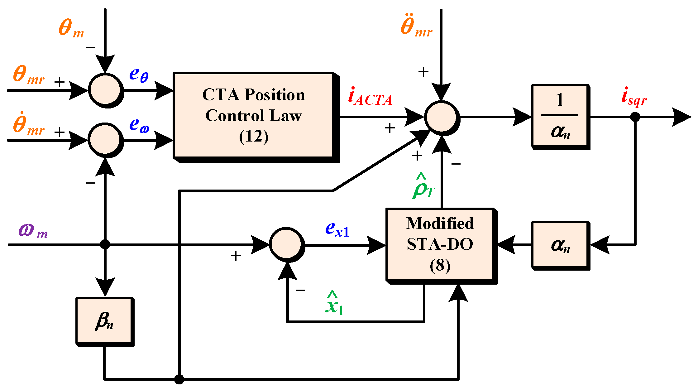
A novel composite position controller, consisting of a CTA-PC and a modified STA-DO, is proposed for the field-oriented controlled PMSM servo system.
(2)
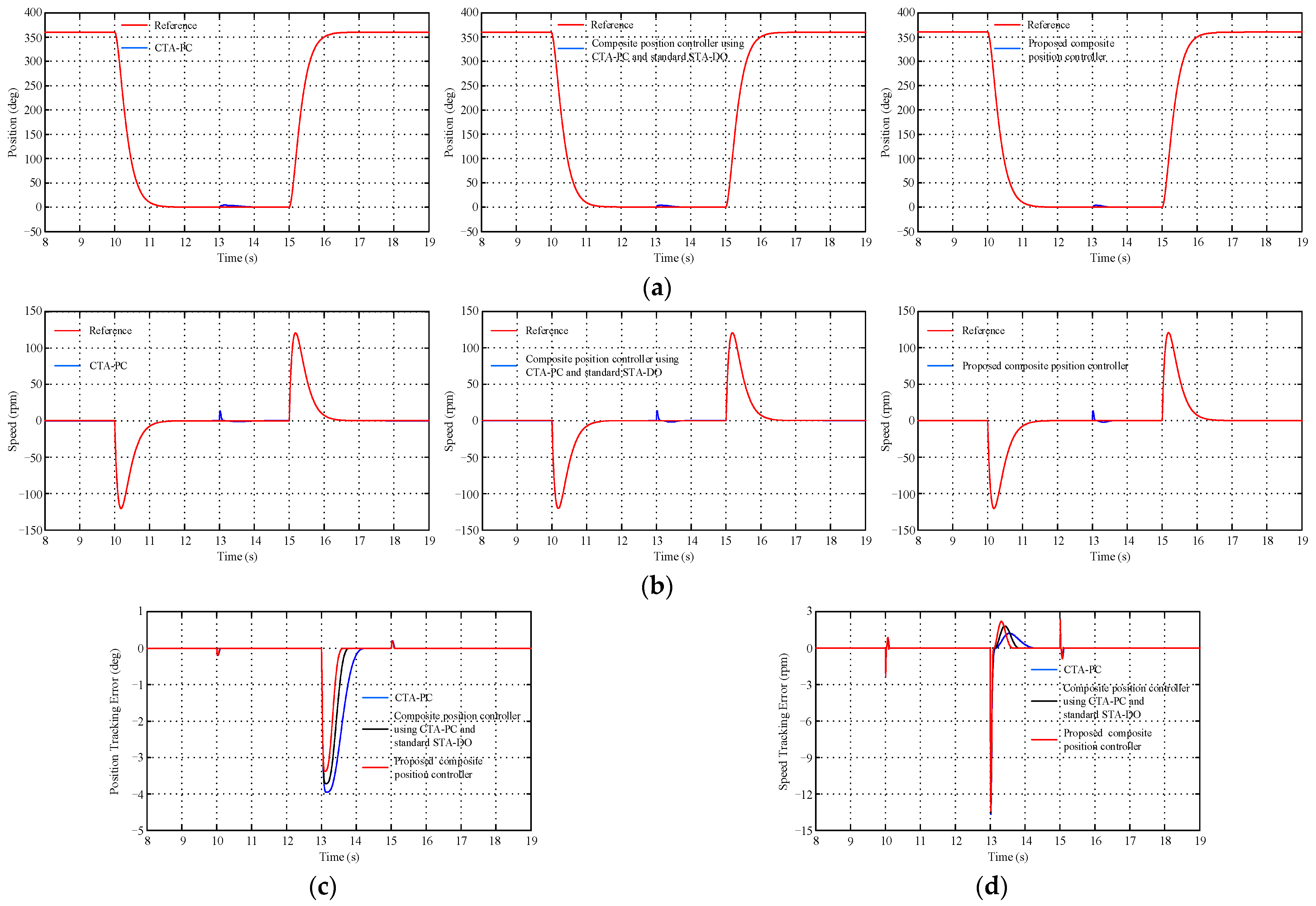
The performance of the proposed composite position controller is compared with that of the CTA-PC and the composite position controller, which combines a CTA-PC with a standard STA-DO.
The remainder of this paper is outlined as follows: Section 2 presents the basic principles of the FOC strategy implemented for the considered PMSM servo system, as well as the dynamic model of this system. Section 3 details the design of the proposed composite position controller. Section 4 presents and analyzes the comparative simulation results. Section 5 offers the conclusion and a brief introduction to the planned future work.

2. Problem Formulation

2.1. Adopted FOC Strategy

In this paper, the surface-mounted PMSM (SMPMSM) servo system fed by a two-level voltage-source inverter is considered. Regarding the rotor position tracking, an FOC strategy employing a dual-loop cascade structure is adopted, as illustrated in Figure 1. The adopted FOC strategy is designed based on the rotor reference coordinate system, also referred to as the dq coordinate system. As shown in Figure 1,   θ m   is the measured mechanical rotor position;   ω m   denotes the mechanical rotor speed calculated from   θ m ; i s   represents the measured stator current vector of the SMPMSM; i s d and i s q represent the direct- and quadrature-axis stator current components, respectively; i s d r is the reference direct-axis stator current component; n p denotes the pole pairs of the SMPMSM; U d c is the dc-bus voltage; and   S   represents the switching state vector based on the modulation algorithm applied to the inverter. The adopted FOC strategy contains three parts: the rotor position control loop, the stator current control loop, and the space-vector pulse-width modulation (SVPWM) module. In the rotor position control loop, the rotor position controller is designed to guarantee both the accurate tracking of   θ m   to its predefined reference   θ m r   and the generation of the reference quadrature-axis stator current component   i s q r . In the stator current control loop, two identical stator current controllers are designed to guarantee both the accurate tracking of   i s d   and   i s q   to their references   i s d r   and   i s q r , respectively, and the generation of the reference direct and quadrature-axis stator voltage components   u s d r   and   u s q r , respectively. After conducting the inverse Park’s transformation, the reference stator voltage components are input into the SVPWM module to generate the switching signals for the inverter. In this FOC strategy, since   i s d r   is set to 0, it is also referred to as the   i s d = 0   control strategy. The main focus of this paper is on the rotor position controller design, while in the stator current control loop, two identical proportional-integral (PI) stator current controllers are adopted.

2.2. Dynamic Model of the SMPMSM Servo System

In the dq coordinate system, the dynamic model of the SMPMSM servo system in terms of   i s d ,   i s q ,   ω m ,   and   θ m   can be described by the following equations [23].
i ˙ s d = R s L s i s d + n p ω m i s q + 1 L s u s d i ˙ s q = n p ω m i s d R s L s i s q n p λ m L s ω m + 1 L s u s q ω ˙ m = 3 n p λ m 2 J i s q 1 J T f 1 J T L θ ˙ m = ω m
where   R s   and   L s   denote the stator resistance and the stator inductance, respectively;   u s d   and   u s q   are the direct- and quadrature-axis stator voltage components, respectively;   λ m   represents the permanent-magnet flux linkage;   J   denotes the moment of inertia; and   T f   and   T L   denote the friction torque and the load torque, respectively.
T f   can be written as the following equation [23].
T f = B m ω m
where   B m   denotes the viscous friction coefficient.
According to (1) and (2), the rotor position dynamics of the SMPMSM servo system can be expressed as
θ ˙ m = ω m ω ˙ m = 3 n p λ m 2 J i s q B m J ω m 1 J T L = α i s q β ω m γ T L
where   α = 3 n p λ m / 2 J ,   β = B m / J , and   γ = 1 / J .
Considering   T f   and   T L   as external disturbances, in addition to mechanical and electrical parametric variations, the rotor position dynamics of the SMPMSM servo system can be formulated as
θ ˙ m = ω m ω ˙ m = α n + α i s q β n + β ω m γ n + γ T L = α n i s q β n ω m + ρ T
where   α n   and   Δ α   are the nominal value and parametric uncertainty of   α , respectively;   β n   and   Δ β   denote the nominal value and parametric uncertainty of   β , respectively;   γ n   and   Δ γ   represent the nominal value and parametric uncertainty of   γ , respectively; and   ρ T   denotes the total disturbance described by
ρ T = α i s q β ω m γ n + γ T L
It is assumed that   ρ T   and   ρ ˙ T   are confined to the bounds   ρ T H 1   and   ρ ˙ T H 2 , where H 1   and   H 2   are positive constants.

3. Position Controller Design

3.1. Rotor Position Tracking Error Dynamics

The rotor position tracking error   e θ   and the rotor speed tracking error   e ω   are defined as
e θ = θ m r θ m ,   e ω = θ ˙ m r ω m
On the basis of (4) and (5), the rotor position tracking error dynamics of the SMPMSM servo system can be obtained as
e ˙ θ = θ ˙ m r θ ˙ m = e ω ,   e ˙ ω = θ ¨ m r ω ˙ m = θ ¨ m r α n i s q + β n ω m ρ T
Forcing   e θ   to 0 is the control objective.

3.2. Modified STA-DO Design

It can be seen that   ρ T , which needs to be compensated for in (6), also appears in the   ω m dynamics shown in (4). Consequently, the DO can be designed based on the   ω m -dynamics shown in (4).
According to (4), the   ω m -dynamics of the SMPMSM servo system can be rewritten as the following equations by selecting   ρ T   as the extended state variable.
x ˙ 1 = α n i s q β n ω m + x 2 ,   x ˙ 2 = ρ ˙ T
where x 1 = ω m and x 2 = ρ T .
Based on (7), the modified STA-DO for   ρ T   can be designed as
x ^ ˙ 1 = α n i s q β n ω m + x ^ 2 + a 1 e x 1 sgn e x 1 + a 2 e x 1 x ^ ˙ 2 = a 3 sgn e x 1 + a 4 e x 1
where x ^ 1 = ω ^ m and x ^ 2 = ρ ^ T represent the estimated mechanical rotor speed and total disturbance, respectively; e x 1 = x 1 x ^ 1 = ω m ω ^ m   represents the chosen sliding variable for the DO;   a 1 ,   a 2 ,   a 3 , and   a 4   are positive constant gains of the DO; and sgn( e x 1 ) denotes the sign function written as
sgn e x 1 = + 1 ,   if e x 1 > 0 0 ,   if   e x 1 = 0 1 ,   if e x 1 < 0
According to (7) and (8), defining   e x 2 = x 2 x ^ 2 = ρ T ρ ^ T   as the estimation error for the total disturbance, the estimation error dynamics for the modified STA-DO can be derived as
e ˙ x 1 = a 1 e x 1 sgn e x 1 a 2 e x 1 + e x 2 e ˙ x 2 = a 3 sgn e x 1 a 4 e x 1 + ρ ˙ T
In theory, the following theorem guarantees the finite-time convergence of   e x 1   and e x 2   to the origin.
Theorem 1. 
Considering system (9) and   ρ ˙ T H 2 , if   a 1 ,   a 2 ,   a 3 ,   and   a 4   are selected as (10),  e x 1   and   e x 2   will converge to the origin in finite time.
a 1 > 0 ,   a 2 > 0 ,   a 3 > 3 H 2 + 2 H 2 2 a 1 2 ,   a 4 > 2 + 3 a 1 2 + 9 H 2 2 4 a 1 2 a 3 12 H 2 a 1 2 8 H 2 2 a 2 2
Proof. 
See Appendix A. □

3.3. Proposed Composite Position Controller

Based on (6), the proposed composite position control law is designed as follows:
i s q r = 1 α n i C T A + θ ¨ m r + β n ω m ρ ^ T
where   i C T A   is written as
i C T A = L 2 / 3 b 1 e θ 1 / 3 sgn e θ + L 1 / 2 b 2 e ω 1 / 2 sgn e ω + i ¯ 1 i ¯ ˙ 1 = L b 3 sgn e θ + b 4 sgn e ω
where L ,   b 1 ,   b 2 ,   b 3 ,   and   b 4   are positive constant gains of the controller.
Remark 1. 
The CTA position control law is obtained by eliminating   ρ ^ T   in (11).
Remark 2. 
The composite speed control law comprising a CTA position control law with a standard STA-DO is obtained by setting   a 2 = a 4 = 0   in (8).
Figure 2 describes the block diagram of the proposed composite position controller.
Substituting (11) into (6), the closed-loop controlled rotor position tracking error dynamics with the proposed composite position control law is expressed as
e ˙ θ = e ω e ˙ ω = L 2 / 3 b 1 e θ 1 / 3 sgn e θ L 1 / 2 b 2 e ω 1 / 2 sgn e ω i ¯ 2 i ¯ ˙ 2 = L b 3 sgn e θ + b 4 sgn e ω e ˙ x 2
In theory, the following theorem guarantees the finite-time convergence of   e θ   and e ω   to the origin.
Theorem 2 
([65]). Considering system (13), suppose that   e ˙ x 2 H 3   for a positive constant   H 3 ; if  L ,   b 1 ,   b 2 ,   b 3 ,   and   b 4   are selected as a set in Table 1,  e θ   and  e ω   will converge to the origin in finite time.

4. Simulation Results

In this paper, the software MATLAB/Simulink is adopted to build the two-level voltage-source inverter-fed SMPMSM servo system for the simulation tests. The sampling period is selected as   5   μ s , the switching frequence of the inverter is   10,000   H z , U d c is 300   V , and the parameters of the considered SMPMSM are listed in Table 2 [87,88]. Regarding each PI stator current controller, its gains are chosen to ensure that the transfer function of each stator current control loop acts as a first-order low-pass filter with a specified bandwidth [23]. In this paper, the gains of each PI stator current controller are chosen based on the aforementioned nominal values of   R s   and   L s in Table 2 such that the bandwidth of each stator current control loop is 500 Hz.
To verify the effectiveness and superiority of the proposed composite position controller, four comparative simulation tests are carried out under the   i s d = 0   control strategy depicted in Figure 1. These tests compare the performance of the CTA-PC, the composite position controller using a CTA-PC and a standard STA-DO, and the proposed composite position controller. The parameters of these tested position controllers are listed in Table 3, where set 1 from Table 1 is selected for the CTA-PC, and   L   is selected as 400.
In test 1, a sinusoidal waveform of   θ m r   with an amplitude of   360 °   and a period of   5.0   s   is selected, and the value of   T L   is suddenly changed from   0   N m   to   3.0   N m   at   8.0   s . Regarding the parametric uncertainties in the rotor position tracking error dynamics in the SMPMSM model, the value of   J   is adjusted to 1.5 times its nominal value to account for the parametric uncertainty of   J ; the value of   λ m   is adjusted to 0.9 times its nominal value to account for the parametric uncertainty of   λ m ; and the value of   B m   is adjusted to twice its nominal value to account for the parametric uncertainty of   B m . The waveforms of   θ m r ,   θ m ,   ω m r ,   ω m ,   e θ , and   e ω   for three tested position controllers in this test are presented in Figure 3. The dynamic performance of these position controllers in terms of rotor position tracking is shown in Table 4. Here, a tolerance band of   ± 0.1   d e g   is adopted to calculate the settling time. The test results show that among the tested position controllers, the CTA-PC achieves the largest maximum tracking error and the longest settling time. In comparison, the composite position controller, which combines a CTA-PC with a standard STA-DO, exhibits a smaller maximum tracking error and shorter settling time than the individual CTA-PC. Among the tested position controllers, the smallest maximum tracking error and shortest settling time are achieved by the proposed composite position controller. Specifically, this position controller achieves a reduction of 19.13% in the maximum tracking error and 53.01% in the settling time compared with the CTA-PC, and 13.87% in the maximum tracking error and 27.78% in the settling time compared with the composite position controller combining a CTA-PC with a standard STA-DO.
In test 2, the same waveform of   θ m r   that is used in test 1 is adopted, and the value of   T L   is also suddenly changed from   0   N m   to   3.0   N m   at   8.0   s . Regarding the parametric uncertainties in the rotor position tracking error dynamics in the SMPMSM model, the value of   J   is adjusted to 3 times its nominal value to account for the parametric uncertainty of   J ; the value of   λ m   is adjusted to 1.1 times its nominal value to account for the parametric uncertainty of   λ m ; and the value of   B m   is adjusted to 6 times its nominal value to account for the parametric uncertainty of   B m . The waveforms of   θ m r ,   θ m ,   ω m r ,   ω m , e θ , and   e ω   for three tested position controllers in this test are presented in Figure 4. The dynamic performance of these position controllers in terms of rotor position tracking is shown in Table 5. Here, the same tolerance band used to calculate the settling time in test 1 is adopted. The test results indicate that, compared with other tested position controllers, the CTA-PC records the maximum value in tracking error and the longest settling time. On the other hand, the composite position controller, which combines a CTA-PC with a standard STA-DO, achieves a reduction in both the maximum tracking error and the settling time when compared with the individual CTA-PC. The proposed composite position controller distinguishes itself by achieving the lowest maximum tracking error and the quickest convergence among the tested position controllers.
In test 3, a second-order reference model with a rise time of 0.6   s ,   as described in (14) and proposed in [89,90], is adopted to model the periodical step waveform of   θ m r   with an amplitude of   360 °   and a period of   5.0   s , and the value of   T L   is suddenly changed from   3.0   N · m   to   0.5   N · m   at   13.0   s . The parametric uncertainties in the rotor position tracking error dynamics in the SMPMSM model are selected to be the same as those in test 1.
ω n 2 s 2 + 2 ζ ω n s + ω n 2 = 30 s 2 + 11 s + 30
where ζ and   ω n   denote the damping ratio and undamped natural frequency, respectively.
The waveforms of   θ m r ,   θ m ,   ω m r ,   ω m ,   e θ , and   e ω   for three tested position controllers in this test are presented in Figure 5. The dynamic performance of these position controllers in terms of rotor position tracking is shown in Table 6. Here, the same tolerance band used to calculate the settling time in test 1 is adopted. It is clear that that the CTA-PC has the highest maximum tracking error and the longest settling time among the tested position controllers. In contrast, the composite position controller combining a CTA-PC with a standard STA-DO demonstrates improvements with a lower maximum tracking error and a shorter settling time than the individual CTA-PC. The proposed composite position controller achieves further reductions in both maximum tracking error and settling time compared to the previously mentioned two position controllers. Specifically, it reduces the maximum tracking error by 17.07% and the settling time by 51.49% relative to the CTA-PC, and by 11.67% and 25.29%, respectively, in comparison to the composite position controller combining a CTA-PC and a standard STA-DO.
In test 4, the same waveform of   θ m r   used in test 3 is adopted, and the value of   T L   is also suddenly changed from   3.0   N · m   to   0.5   N · m   at   13.0   s . The parametric uncertainties in the rotor position tracking error dynamics in the SMPMSM model are selected to be the same as those in test 2. The waveforms of   θ m r ,   θ m ,   ω m r ,   ω m ,   e θ , and   e ω   for three tested position controllers in this test are presented in Figure 6. The dynamic performance of these position controllers in terms of rotor position tracking is shown in Table 7. Here, the same tolerance band used to calculate the settling time in test 1 is adopted. The test results indicate that the CTA-PC records the highest maximum tracking error and the longest settling time. With the help of the standard STA-DO, the composite position controller combining a CTA-PC with this DO reduces both the maximum tracking error and the settling time. By using the modified STA-DO to replace its standard counterpart, the proposed composite position controller attains the lowest maximum tracking error and the shortest settling time.

5. Conclusions and Future Work

In this paper, a novel composite position controller is designed for the dual-loop FOC strategy of the SMPMSM servo system. Adhering to the principle of DO-based control, it integrates a position controller and a DO, both based on SOSM algorithms. Specifically, the position controller, aimed at finite-time rotor position tracking, is designed using the CTA, while the DO, which compensates for external disturbances and parametric uncertainties in the rotor position tracking error to enhance dynamic performance, is based on the modified STA. Within a specific FOC strategy of the SMPMSM servo system, the performances of the CTA-PC, the composite position controller combining a CTA-PC with a standard STA-DO, and the proposed composite position controller are compared through simulation tests performed on the software MATLAB/Simulink. The simulation results validate the proposed composite position controller’s effectiveness and its superiority over comparable position controllers.
For future work, further verification of the proposed composite position controller through experiments is planned. In addition, it is also planned to explore the application of the CTA-based controllers and observers to other parts of the FOC strategy of the SMPMSM-based system.

Funding

This research received no external funding.

Data Availability Statement

The original contributions presented in the study are included in the article, further inquiries can be directed to the corresponding author.

Conflicts of Interest

The author declares that the research was conducted in the absence of any commercial or financial relationship that could be construed as a potential conflict of interest.

Appendix A

Firstly, the vector   ξ   is defined as
ξ = ξ 1 ξ 2 ξ 3 = e x 1 sgn e x 1 e x 1 e x 2
According to (9) and (A1),   ξ ˙   can be derived as
ξ ˙ = ξ ˙ 1 ξ ˙ 2 ξ ˙ 3 = 1 2 e x 1 1 / 2 e ˙ x 1 e ˙ x 1 e ˙ x 2 = 1 2 e x 1 1 / 2 a 1 e x 1 sgn e x 1 a 2 e x 1 + e x 2 a 1 e x 1 sgn e x 1 a 2 e x 1 + e x 2 a 3 sgn e x 1 a 4 e x 1 + ρ ˙ T
The following Lyapunov candidate function   V 1   is selected [75].
V 1 = ξ T P 1 ξ , P 1 = 1 2 4 a 3 + a 1 2 a 1 a 2 a 1 a 1 a 2 2 a 4 + a 2 2 a 2 a 1 a 2 2
Since   a i > 0   ( i = 1 , 2 , 3 , 4 ),   P 1   is a positive definite symmetric matrix. Consequently, the eigenvalues of   P 1   are positive, ensuring the following inequality.
λ min P 1 ξ 2 2 V 1 λ max P 1 ξ 2 2
where λ m i n { P 1 } and λ m a x { P 1 } are the minimum and maximum eigenvalues of   P 1 , respectively, and   · 2   represents the Euclidean norm of a vector.
According to (A3),   V 1   can be rewritten as
V 1 = 2 a 3 + 1 2 a 1 2 ξ 1 2 + a 4 + 1 2 a 2 2 ξ 2 2 + ξ 3 2 + a 1 a 2 ξ 1 ξ 2 a 1 ξ 1 ξ 3 a 2 ξ 2 ξ 3
Based on (A1), (A2), and (A5),   V ˙ 1   can be derived as
V ˙ 1 = 2 a 3 + 1 2 a 1 2 2 ξ 1 ξ ˙ 1 + a 4 + 1 2 a 2 2 2 ξ 2 ξ ˙ 2 + 2 ξ 3 ξ ˙ 3 + a 1 a 2 ξ ˙ 1 ξ 2 + ξ 1 ξ ˙ 2 a 1 ξ ˙ 1 ξ 3 + ξ 1 ξ ˙ 3 a 2 ξ ˙ 2 ξ 3 + ξ 2 ξ ˙ 3 = 2 a 3 + 1 2 a 1 2 2 e x 1 1 / 2 sgn ( e x 1 ) 1 2 e x 1 1 / 2 e ˙ x 1 + a 4 + 1 2 a 2 2 2 e x 1 e ˙ x 1 + 2 e x 2 e ˙ x 2 + a 1 a 2 1 2 e x 1 1 / 2 e ˙ x 1 e x 1 + e x 1 1 / 2 sgn ( e x 1 ) e ˙ x 1 a 1 1 2 e x 1 1 / 2 e ˙ x 1 e x 2 + e x 1 1 / 2 sgn ( e x 1 ) e ˙ x 2 a 2 e ˙ x 1 e x 2 + e x 1 e ˙ x 2 = 2 a 3 + 1 2 a 1 2 a 1 e x 1 1 / 2 sgn e x 1 a 2 e x 1 + e x 2 sgn ( e x 1 ) + 2 a 4 + a 2 2 e x 1 a 1 e x 1 1 / 2 sgn e x 1 a 2 e x 1 + e x 2 + 2 e x 2 a 3 sgn e x 1 a 4 e x 1 + ρ ˙ T + a 1 a 2 e x 1 2 e x 1 1 / 2 + e x 1 1 / 2 sgn ( e x 1 ) a 1 e x 1 1 / 2 sgn e x 1 a 2 e x 1 + e x 2 a 1 e x 2 2 e x 1 1 / 2 a 1 e x 1 1 / 2 sgn e x 1 a 2 e x 1 + e x 2 a 1 e x 1 1 / 2 sgn ( e x 1 ) a 3 sgn e x 1 a 4 e x 1 + ρ ˙ T a 2 e x 2 a 1 e x 1 1 / 2 sgn e x 1 a 2 e x 1 + e x 2 a 2 e x 1 a 3 sgn e x 1 a 4 e x 1 + ρ ˙ T = a 1 2 a 3 + 1 2 a 1 2 e x 1 1 / 2 a 2 2 a 3 + 1 2 a 1 2 e x 1 + 2 a 3 + 1 2 a 1 2 e x 2 sgn ( e x 1 ) a 1 2 a 4 + a 2 2 e x 1 3 / 2 a 2 2 a 4 + a 2 2 e x 1 2 + 2 a 4 + a 2 2 e x 1 e x 2 2 a 3 e x 2 sgn e x 1 2 a 4 e x 1 e x 2 + 2 ρ ˙ T e x 2 + a 1 a 2 1 2 a 1 e x 1 1 2 a 2 e x 1 2 e x 1 1 / 2 + 1 2 e x 1 1 / 2 e x 2 sgn ( e x 1 ) a 1 e x 1 a 2 e x 1 3 / 2 + e x 1 1 / 2 e x 2 sgn ( e x 1 ) + 1 2 a 1 2 e x 2 sgn e x 1 + 1 2 a 1 a 2 e x 2 e x 1 1 / 2 sgn ( e x 1 ) a 1 e x 2 2 2 e x 1 1 / 2 + a 1 a 3 e x 1 1 / 2 + a 1 a 4 e x 1 3 / 2 a 1 ρ ˙ T e x 1 1 / 2 sgn ( e x 1 ) + a 1 a 2 e x 2 e x 1 1 / 2 sgn e x 1 + a 2 2 e x 1 e x 2 a 2 e x 2 2 + a 2 a 3 e x 1 + a 2 a 4 e x 1 2 a 2 ρ ˙ T e x 1 = a 1 2 a 3 + a 1 2 2 e x 1 1 / 2 ξ 1 2 a 2 a 4 + a 2 2 ξ 2 2 a 1 2 a 4 + 5 a 2 2 2 e x 1 1 / 2 ξ 2 2 a 2 ξ 3 2 a 2 a 3 + 2 a 1 2 ξ 1 2 + a 1 2 e x 1 1 / 2 ξ 1 ξ 3 + 2 a 2 2 ξ 2 ξ 3 + 3 a 1 a 2 e x 1 1 / 2 ξ 2 ξ 3 a 1 2 e x 1 1 / 2 ξ 3 2 + 2 ρ ˙ T e x 2 a 1 ρ ˙ T e x 1 1 / 2 sgn ( e x 1 ) a 2 ρ ˙ T e x 1 = 1 e x 1 1 / 2 a 1 2 2 a 3 + a 1 2 ξ 1 2 + 2 a 4 + 5 a 2 2 ξ 2 2 + ξ 3 2 2 a 1 ξ 1 ξ 3 6 a 2 ξ 2 ξ 3 a 2 a 3 + 2 a 1 2 ξ 1 2 + a 4 + a 2 2 ξ 2 2 + ξ 3 2 2 a 2 ξ 2 ξ 3 + 2 ρ ˙ T e x 2 a 1 ρ ˙ T e x 1 1 / 2 sgn ( e x 1 ) a 2 ρ ˙ T e x 1
The vector   Ξ   is defined as (A7). Based on (A6) and (A7) and considering   ρ ˙ T H 2 , inequality (A8) is ensured.
Ξ = ξ 1 ξ 2 ξ 3 = e x 1 e x 1 e x 2
V ˙ 1 = 1 e x 1 1 / 2 a 1 2 2 a 3 + a 1 2 ξ 1 2 + 2 a 4 + 5 a 2 2 ξ 2 2 + ξ 3 2 2 a 1 ξ 1 ξ 3 6 a 2 ξ 2 ξ 3 a 2 a 3 + 2 a 1 2 ξ 1 2 + a 4 + a 2 2 ξ 2 2 + ξ 3 2 2 a 2 ξ 2 ξ 3 + 2 ρ ˙ T e x 2 a 1 ρ ˙ T e x 1 1 / 2 sgn ( e x 1 ) a 2 ρ ˙ T e x 1 1 e x 1 1 / 2 a 1 2 2 a 3 + a 1 2 ξ 1 2 + 2 a 4 + 5 a 2 2 ξ 2 2 + ξ 3 2 2 a 1 ξ 1 ξ 3 6 a 2 ξ 2 ξ 3 a 2 a 3 + 2 a 1 2 ξ 1 2 + a 4 + a 2 2 ξ 2 2 + ξ 3 2 2 a 2 ξ 2 ξ 3 + 2 H 2 e x 2 + a 1 H 2 e x 1 1 / 2 + a 2 H 2 e x 1 = 1 e x 1 1 / 2 a 1 2 2 a 3 + a 1 2 ξ 1 2 + 2 a 4 + 5 a 2 2 ξ 2 2 + ξ 3 2 2 a 1 ξ 1 ξ 3 6 a 2 ξ 2 ξ 3 1 e x 1 1 / 2 a 1 2 2 e x 1 1 / 2 H 2 e x 1 1 / 2 4 H 2 a 1 e x 1 1 / 2 e x 2 a 2 a 3 + 2 a 1 2 ξ 1 2 + a 4 + a 2 2 ξ 2 2 + ξ 3 2 2 a 2 ξ 2 ξ 3 H 2 e x 1 = 1 e x 1 1 / 2 Ξ T Θ 1 Ξ Ξ T Θ 2 Ξ
with
Θ 1 = a 1 2 2 a 3 + a 1 2 2 H 2 0 a 1 2 H 2 a 1 0 2 a 4 + 5 a 2 2 3 a 2 a 1 2 H 2 a 1 3 a 2 1 ,   Θ 2 = a 2 a 3 + 2 a 1 2 H 2 0 0 0 a 4 + a 2 2 a 2 0 a 2 1
Substituting (10) into (A9), both   Θ 1   and   Θ 2   are confirmed to be positive definite symmetric matrices, ensuring the following inequalities.
λ min Θ 1 Ξ 2 2 Ξ T Θ 1 Ξ λ max Θ 1 Ξ 2 2 ,   λ min Θ 2 Ξ 2 2 Ξ T Θ 2 Ξ λ max Θ 2 Ξ 2 2
Based on (A8) and (A10), the following inequality is ensured.
V ˙ 1 1 e x 1 1 / 2 Ξ T Θ 1 Ξ Ξ T Θ 2 Ξ 1 e x 1 1 / 2 Ξ T Θ 1 Ξ 1 e x 1 1 / 2 λ min Θ 1 Ξ 2 2
Considering Ξ 2 2 = ξ 2 2 , the following inequality is ensured.
e x 1 e x 1 + e x 1 2 + e x 2 2 = Ξ 2 2 = ξ 2 2
Based on (A4) and (A12), the following inequality is ensured.
e x 1 1 / 2 ξ 2 V 1 λ min P 1
Based on (A4), (A11), and (A13), the following inequality is ensured.
V ˙ 1 λ min P 1 λ min Θ 1 λ max P 1 V 1 = ϖ 1 V 1
Based on (A14) and the comparison principle [91], the finite-time convergence of   e x 1   and   e x 2   to the origin is guaranteed.

References

  1. Krishnan, R. Permanent Magnet Synchronous and Brushless DC Motor Drives; CRC Press: Boca Raton, FL, USA, 2009. [Google Scholar]
  2. Gieras, J.F. Permanent Magnet Motor Technology: Design and Applications, 3rd ed.; CRC Press: Boca Raton, FL, USA, 2009. [Google Scholar]
  3. Chau, K.T. Electric Vehicle Machines and Drives: Design, Analysis and Application; Wiley-IEEE Press: Singapore, 2015. [Google Scholar]
  4. Nguyen, P.H.; Hoang, E.; Gabsi, M. Performance synthesis of permanent-magnet synchronous machines during the driving cycle of a hybrid electric vehicle. IEEE Trans. Veh. Technol. 2011, 60, 1991–1998. [Google Scholar] [CrossRef]
  5. Liu, C.; Chau, K.T.; Lee, C.H.T.; Song, Z. A critical review of advanced electric machines and control strategies for electric vehicles. Proc. IEEE 2021, 109, 1004–1028. [Google Scholar] [CrossRef]
  6. Jonkman, J.M. Dynamics Modeling and Loads Analysis of an Offshore Floating Wind Turbine. Ph.D. Thesis, University of Colorado at Boulder, Boulder, CO, USA, 2007. [Google Scholar]
  7. Yaramasu, V.; Wu, B.; Sen, P.C.; Kouro, S.; Narimani, M. High-power wind energy conversion systems: State-of-the-art and emerging technologies. Proc. IEEE 2015, 103, 740–788. [Google Scholar] [CrossRef]
  8. Le, X.C.; Duong, M.Q.; Le, K.H. Review of the modern maximum power tracking algorithms for permanent magnet synchronous generator of wind power conversion systems. Energies 2023, 16, 402. [Google Scholar] [CrossRef]
  9. Choi, J.H.; Jang, S.M.; Sung, S.Y.; Kim, J.M.; Park, Y.S.; Kim, Y.J.; Oh, D.H. Operating range evaluation of double-side permanent magnet synchronous motor/generator for flywheel energy storage system. IEEE Trans. Magn. 2013, 49, 4076–4079. [Google Scholar] [CrossRef]
  10. Li, Y.; Zhu, C.; Wu, L.; Zheng, Y. Multi-objective optimal design of high-speed surface-mounted permanent magnet synchronous motor for magnetically levitated flywheel energy storage system. IEEE Trans. Magn. 2019, 55, 8202708. [Google Scholar] [CrossRef]
  11. Ji, W.; Ni, F.; Gao, D.; Luo, S.; Lv, Q.; Lv, D. Electromagnetic design of high-power and high-speed permanent magnet synchronous motor considering loss characteristics. Energies 2021, 14, 3622. [Google Scholar] [CrossRef]
  12. Hong, D.K.; Hwang, W.; Lee, J.Y.; Woo, B.C. Design, analysis, and experimental validation of a permanent magnet synchronous motor for articulated robot applications. IEEE Trans. Magn. 2018, 54, 8201304. [Google Scholar] [CrossRef]
  13. Luu, P.T.; Lee, J.Y.; Lee, J.H.; Park, J.W. Electromagnetic and thermal analysis of permanent-magnet synchronous motors for cooperative robot applications. IEEE Trans. Magn. 2020, 56, 7512804. [Google Scholar] [CrossRef]
  14. Zhen, S.; Li, Y.; Liu, X.; Wang, J.; Chen, F.; Chen, X. A Lyapunov-based robust control for permanent magnet synchronous motor in the modular joint of collaborative robot. Robotica 2023, 41, 1389–1406. [Google Scholar] [CrossRef]
  15. Ocak, O.; Onsal, M.; Aydin, M. Development of a 7.5 kW high speed interior permanent magnet synchronous spindle motor for CNC milling machine. In Proceedings of the 2018 XIII International Conference on Electrical Machines, Alexandroupoli, Greece, 3–6 September 2018. [Google Scholar]
  16. Wang, L.; Tang, Z.; Zhang, P.; Liu, X.; Wang, D.; Li, X. Double extended sliding mode observer-based synchronous estimation of total inertia and load torque for PMSM-driven spindle-tool systems. IEEE Trans. Ind. Inform. 2023, 19, 8496–8507. [Google Scholar] [CrossRef]
  17. Zhang, W.; Zhang, X.; Zhao, W. Influence of nonlinearity of servo system electrical characteristics on motion smoothness of precision CNC machine tools. Precis. Eng. 2023, 83, 82–101. [Google Scholar] [CrossRef]
  18. Huang, Z.; Huang, X.; Zhang, J.; Fang, Y.; Lu, Q. Design of an interior permanent magnet synchronous traction motor for high speed railway applications. In Proceedings of the 6th IET International Conference on Power Electronics, Machines and Drives, Bristol, UK, 27–29 March 2012. [Google Scholar]
  19. Yu, D.; Huang, X.Y.; Fang, Y.T.; Zhang, J. Design and comparison of interior permanent magnet synchronous traction motors for high speed railway applications. In Proceedings of the 2017 IEEE Workshop on Electrical Machines Design, Control and Diagnosis, Nottingham, UK, 20–21 April 2017. [Google Scholar]
  20. Torrent, M.; Perat, J.I.; Jiménez, J.A. Permanent magnet synchronous motor with different rotor structures for traction motor in high speed trains. Energies 2018, 11, 1549. [Google Scholar] [CrossRef]
  21. Lin, F.-J. Real-time IP position controller design with torque feedforward control for PM synchronous motor. IEEE Trans. Ind. Electron. 1997, 44, 398–407. [Google Scholar]
  22. Lin, F.-J.; Lin, Y.-S. A robust PM synchronous motor drive with adaptive uncertainty observer. IEEE Trans. Energy Convers. 1999, 14, 989–995. [Google Scholar]
  23. Sul, S.-K. Control of Electric Machine Drive Systems; Wiley-IEEE Press: Hoboken, NJ, USA, 2010. [Google Scholar]
  24. Li, S.; Yang, J.; Chen, W.-H.; Chen, X. Disturbance Observer-Based Control Methods and Applications; CRC Press: Boca Raton, FL, USA, 2017. [Google Scholar]
  25. Yang, J.; Chen, W.H.; Li, S.; Guo, L.; Yan, Y. Disturbance/uncertainty estimation and attenuation techniques in PMSM drives—A survey. IEEE Trans. Ind. Electron. 2017, 64, 3273–3285. [Google Scholar] [CrossRef]
  26. Liu, T.-H.; Pu, H.-T.; Lin, C.-K. Implementation of an adaptive position control system of a permanent-magnet synchronous motor and its application. IET Electr. Power Appl. 2010, 4, 121–130. [Google Scholar] [CrossRef]
  27. Yu, J.; Shi, P.; Yu, H.; Chen, B.; Lin, C. Approximation-based discrete-time adaptive position tracking control for interior permanent magnet synchronous motors. IEEE Trans. Cybern. 2015, 45, 1363–1371. [Google Scholar] [CrossRef]
  28. Peresada, S.; Nikonenko, Y.; Reshetnyk, V.; Rodkin, D. Adaptive position control and self-commissioning of the interior permanent magnet synchronous motors. In Proceedings of the 2019 IEEE International Conference on Modern Electrical and Energy Systems, Kremenchuk, Ukraine, 23–25 September 2019. [Google Scholar]
  29. Lin, F.J.; Lin, C.H. A permanent-magnet synchronous motor servo drive using self-constructing fuzzy neural network controller. IEEE Trans. Energy Convers. 2004, 19, 66–72. [Google Scholar] [CrossRef]
  30. Kumar, V.; Gaur, P.; Mittal, A.P. ANN based self tuned PID like adaptive controller design for high performance PMSM position control. Expert Syst. Appl. 2014, 41, 7995–8002. [Google Scholar] [CrossRef]
  31. Tian, Z.; Guo, H.; Ding, X.; He, X. A PID neural network control for position servo system with gear box at variable load. In Proceedings of the 2016 IEEE Vehicle Power and Propulsion Conference, Hangzhou, China, 17–20 October 2016. [Google Scholar]
  32. Uddin, M.N.; Lau, J. Adaptive-backstepping-based design of a nonlinear position controller for an IPMSM servo drive. Can. J. Elect. Comput. Eng. 2007, 32, 97–102. [Google Scholar] [CrossRef]
  33. Linares-Flores, J.; García-Rodríguez, C.; Sira-Ramirez, H.; Ramírez-Cárdenas, O.D. Robust backstepping tracking controller for low-speed PMSM positioning system: Design, analysis, and implementation. IEEE Trans. Ind. Inform. 2015, 11, 1130–1141. [Google Scholar] [CrossRef]
  34. El-Sousy, F.F.; El-Naggar, M.F.; Amin, M.; Abu-Siada, A.; Abuhasel, K.A. Robust adaptive neural-network backstepping control design for high-speed permanent-magnet synchronous motor drives: Theory and experiments. IEEE Access 2019, 7, 99327–99348. [Google Scholar] [CrossRef]
  35. Fuentes, E.; Kennel, R.M. A finite-set model predictive position controller for the permanent magnet synchronous motor. In Proceedings of the 2013 IEEE International Symposium on Sensorless Control for Electrical Drives and Predictive Control of Electrical Drives and Power Electronics, Munich, Germany, 17–19 October 2013. [Google Scholar]
  36. Mubarok, M.S.; Liu, T.H. Implementation of predictive controllers for matrix-converter-based interior permanent magnet synchronous motor position control systems. IEEE J. Emerg. Sel. Top. Power Electron. 2019, 7, 261–273. [Google Scholar] [CrossRef]
  37. Wang, Y.; Liu, X. Model predictive position control of permanent magnet synchronous motor servo system with sliding mode observer. Asian J. Control 2023, 25, 443–461. [Google Scholar] [CrossRef]
  38. Lin, C.K.; Liu, T.H.; Yang, S.H. Nonlinear position controller design with input–output linearisation technique for an interior permanent magnet synchronous motor control system. IET Power Electron. 2008, 1, 14–26. [Google Scholar] [CrossRef]
  39. Chen, Y.-T.; Yu, C.-S.; Chen, P.-N. Feedback linearization based robust control for linear permanent magnet synchronous motors. Energies 2020, 13, 5242. [Google Scholar] [CrossRef]
  40. Zhao, Y.; Yu, H.; Wang, S. Development of optimized cooperative control based on feedback linearization and error port-controlled Hamiltonian for permanent magnet synchronous motor. IEEE Access 2021, 9, 141036–141047. [Google Scholar] [CrossRef]
  41. Lin, F.-J.; Chiu, S.-L.; Shyu, K.-K. Novel sliding mode controller for synchronous motor drive. IEEE Trans. Aerosp. Electron. Syst. 1998, 34, 532–542. [Google Scholar]
  42. Lin, F.-J.; Shyu, K.-K.; Lin, Y.-S. Variable structure adaptive control for PM synchronous servo motor drive. IEEE Proc.-Electr. Power Appl. 1999, 146, 173–185. [Google Scholar] [CrossRef]
  43. Wei, R.-J. Total sliding-mode controller for PM synchronous servo motor drive using recurrent fuzzy neural network. IEEE Trans. Ind. Electron. 2001, 48, 926–944. [Google Scholar]
  44. El-Sousy, F.F. Robust tracking control based on intelligent sliding-mode model-following position controllers for PMSM servo drives. J. Power Electron. 2007, 7, 159–173. [Google Scholar]
  45. Utkin, V.I.; Guldner, J.; Shi, J.X. Sliding-Mode Control in Electro-Mechanical Systems, 2nd ed.; CRC Press: Boca Raton, FL, USA, 2009. [Google Scholar]
  46. Wang, S.; Tao, L.; Chen, Q.; Na, J.; Ren, X. USDE-based sliding mode control for servo mechanisms with unknown system dynamics. IEEE/ASME Trans. Mechatron. 2020, 25, 1056–1066. [Google Scholar] [CrossRef]
  47. Lu, H.; Yang, D.; Su, Z. Improved sliding mode control for permanent magnet synchronous motor servo system. IET Power Electron. 2023, 16, 169–179. [Google Scholar] [CrossRef]
  48. El-Sousy, F.F.; Amin, M.M.; Aziz, G.A.A.; Al-Durra, A.; Mohammed, O.A. Optimal super-twisting sliding-mode control using adaptive dynamic programming for uncertain linear-stage considering PMSM servo drive dynamics. In Proceedings of the 2020 IEEE Energy Conversion Congress and Exposition, Detroit, MI, USA, 11–15 October 2020. [Google Scholar]
  49. Gil, J.; You, S.; Lee, Y.; Kim, W. Super twisting-based nonlinear gain sliding mode controller for position control of permanent-magnet synchronous motors. IEEE Access 2021, 9, 142060–142070. [Google Scholar] [CrossRef]
  50. Nguyen, T.H.; Nguyen, T.T.; Le, K.M.; Tran, H.N.; Jeon, J.W. An adaptive backstepping sliding-mode control for improving position tracking of a permanent-magnet synchronous motor with a nonlinear disturbance observer. IEEE Access 2023, 11, 19173–19185. [Google Scholar] [CrossRef]
  51. Liang, D.; Li, J.; Qu, R. Sensorless control of permanent magnet synchronous machine based on second-order sliding-mode observer with online resistance estimation. IEEE Trans. Ind. Appl. 2017, 53, 3672–3682. [Google Scholar] [CrossRef]
  52. Liu, Y.-C.; Laghrouche, S.; N’Diaye, A.; Cirrincione, M. Active-flux-based super-twisting sliding mode observer for sensorless vector control of synchronous reluctance motor drives. In Proceedings of the 2018 7th International Conference on Renewable Energy Research and Applications, Paris, France, 14–17 October 2018. [Google Scholar]
  53. Sadeghi, R.; Madani, S.M.; Ataei, M.; Kashkooli, M.A.; Ademi, S. Super-twisting sliding mode direct power control of a brushless doubly fed induction generator. IEEE Trans. Ind. Electron. 2018, 65, 9147–9156. [Google Scholar] [CrossRef]
  54. Wang, H.; Ge, X.; Liu, Y.-C. Second-order sliding-mode MRAS observer based sensorless vector control of linear induction motor drives for medium-low speed maglev applications. IEEE Trans. Ind. Electron. 2018, 65, 9938–9952. [Google Scholar] [CrossRef]
  55. Scalcon, F.P.; Fang, G.; Vieira, R.P.; Gründling, H.A.; Emadi, A. Discrete-time super-twisting sliding mode current controller with fixed switching frequency for switched reluctance motors. IEEE Trans. Power Electron. 2022, 37, 3321–3333. [Google Scholar] [CrossRef]
  56. Wang, H.; Yang, Y.; Ge, X.; Zuo, Y.; Feng, X.; Chen, D.; Liu, Y.-C. Speed-sensorless control of induction motor drives with a STA-FLL speed estimation scheme. IEEE Trans. Ind. Electron. 2023, 70, 12168–12180. [Google Scholar] [CrossRef]
  57. Shtessel, Y.; Edwards, C.; Fridman, L.; Levant, A. Sliding Mode Control and Observation; Birkhäuser: New York, NY, USA, 2014. [Google Scholar]
  58. Levant, A. Sliding order and sliding accuracy in sliding mode control. Int. J. Control 1993, 58, 1247–1263. [Google Scholar] [CrossRef]
  59. Derafa, L.; Benallegue, A.; Fridman, L. Super twisting control algorithm for the attitude tracking of a four rotors. J. Frankl. Inst. 2012, 349, 685–699. [Google Scholar] [CrossRef]
  60. Vazquez, C.; Collado, J.; Fridman, L. Super twisting control of a parametrically excited overhead crane. J. Frankl. Inst. 2014, 351, 2283–2298. [Google Scholar] [CrossRef]
  61. Liu, Y.-C.; Laghrouche, S.; N’Diaye, A.; Cirrincione, M. Hermite neural network-based second-order sliding-mode control of synchronous reluctance motor drive systems. J. Frankl. Inst. 2021, 358, 400–427. [Google Scholar] [CrossRef]
  62. Chen, J.; Shuai, Z.; Zhang, H.; Zhao, W. Path following control of autonomous four-wheel-independent-drive electric vehicles via second-order sliding mode and nonlinear disturbance observer techniques. IEEE Trans. Ind. Electron. 2021, 68, 2460–2469. [Google Scholar] [CrossRef]
  63. Basbas, H.; Liu, Y.-C.; Laghrouche, S.; Hilairet, M.; Plestan, F. Review on floating offshore wind turbine models for nonlinear control design. Energies 2022, 15, 5477. [Google Scholar] [CrossRef]
  64. Torres-González, V.; Fridman, L.M.; Moreno, J.A. Continuous twisting algorithm. In Proceedings of the 54th IEEE Conference on Decision and Control, Osaka, Japan, 15–18 December 2015. [Google Scholar]
  65. Torres-González, V.; Sanchez, T.; Fridman, L.M.; Moreno, J.A. Design of continuous twisting algorithm. Automatica 2017, 80, 119–126. [Google Scholar] [CrossRef]
  66. Moreno, J.A.; Negrete, D.Y.; Torres-González, V.; Fridman, L. Adaptive continuous twisting algorithm. Int. J. Control 2016, 89, 1798–1806. [Google Scholar] [CrossRef]
  67. Pérez, U.; Capello, E.; Punta, E.; Perea, J.; Fridman, L. Fault detection and isolation for a 3-DOF helicopter with sliding mode strategies. In Proceedings of the 15th International Workshop on Variable Structure Systems, Graz, Austria, 9–11 July 2018. [Google Scholar]
  68. Pérez-Ventura, U.; Fridman, L.; Capello, E.; Punta, E. Fault tolerant control based on continuous twisting algorithms of a 3-DoF helicopter prototype. Control Eng. Pract. 2020, 101, 104486. [Google Scholar] [CrossRef]
  69. Ríos, H.; Falcón, R.; González, O.A.; Dzul, A. Continuous sliding-mode control strategies for quadrotor robust tracking: Real-time application. IEEE Trans. Ind. Electron. 2019, 66, 1264–1272. [Google Scholar] [CrossRef]
  70. Mechali, O.; Xu, L.; Senouci, A.; Xie, X.; Xin, C.; Mechali, A. Finite-time observer-based robust continuous twisting control for the attitude of an uncertain quadrotor UAV subjected to disturbances. In Proceedings of the 2020 IEEE International Conference on Mechatronics and Automation, Beijing, China, 13–16 October 2020. [Google Scholar]
  71. Savitski, D.; Ivanov, V.; Augsburg, K.; Emmei, T.; Fuse, H.; Fujimoto, H.; Fridman, L.M. Wheel slip control for the electric vehicle with in-wheel motors: Variable structure and sliding mode methods. IEEE Trans. Ind. Electron. 2020, 67, 8535–8544. [Google Scholar] [CrossRef]
  72. Tiwari, P.M. Continuous twisting sliding mode control for spacecraft attitude maneuver. In Proceedings of the IEEE 12th International Conference on Communication Systems and Network Technologies, Bhopal, India, 8–9 April 2023. [Google Scholar]
  73. Gutiérrez-Oribio, D.; Tzortzopoulos, G.; Stefanou, I.; Plestan, F. Earthquake control: An emerging application for robust control. theory and experimental tests. IEEE Trans. Control Syst. Technol. 2023, 31, 1747–1761. [Google Scholar] [CrossRef]
  74. Kumar, V.; Mohanty, S.R. Resilient optimal gain control and continuous twisting observer for enhanced power system performance under uncertainties. IEEE Syst. J. 2023, 17, 2733–2744. [Google Scholar] [CrossRef]
  75. Moreno, J.; Osorio, M. A Lyapunov approach to second-order sliding mode controllers and observers. In Proceedings of the 47th IEEE Conference on Decision and Control, Cancun, Mexico, 9–11 December 2008. [Google Scholar]
  76. Moreno, J.A. On strict Lyapunov functions for some non-homogeneous super-twisting algorithms. J. Frankl. Inst. 2014, 351, 1902–1919. [Google Scholar] [CrossRef]
  77. Yin, Y.; Vazquez, S.; Marquez, A.; Liu, J.; Leon, J.I.; Wu, L.; Franquelo, L.G. Observer-based sliding-mode control for grid-connected power converters under unbalanced grid conditions. IEEE Trans. Ind. Electron. 2022, 69, 517–527. [Google Scholar] [CrossRef]
  78. Luo, W.; Vazquez, S.; Liu, J.; Gordillo, F.; Franquelo, L.G.; Wu, L. Control system design of a three-phase active front end using a sliding-mode observer. IEEE Trans. Syst. Man Cybern. Syst. 2022, 52, 739–748. [Google Scholar] [CrossRef]
  79. Liu, Y.-C.; Laghrouche, S.; Depernet, D.; Djerdir, A.; Cirrincione, M. Disturbance-observer-based complementary sliding-mode speed control for PMSM drives: A super-twisting sliding-mode observer-based approach. IEEE J. Emerg. Sel. Top. Power Electron. 2021, 9, 5416–5428. [Google Scholar] [CrossRef]
  80. Liu, Y.-C.; Laghrouche, S.; Depernet, D.; N’Diaye, A.; Djerdir, A.; Cirrincione, M. Super-twisting sliding-mode observer-based model reference adaptive speed control for PMSM drives. J. Frankl. Inst. 2023, 360, 985–1004. [Google Scholar] [CrossRef]
  81. Derafa, L.; El Hadri, A.; Fridman, L. External perturbation estimation based on super-twisting algorithm for attitude control of UAVs. IFAC Proc. Vol. 2012, 45, 746–752. [Google Scholar] [CrossRef]
  82. Shi, D.; Wu, Z.; Chou, W. Super-twisting extended state observer and sliding mode controller for quadrotor UAV attitude system in presence of wind gust and actuator faults. Electronics 2018, 7, 128. [Google Scholar] [CrossRef]
  83. Muñoz, F.; Bonilla, M.; González-Hernández, I.; Salazar, S.; Lozano, R. Super twisting vs modified super twisting algorithm for altitude control of an unmanned aircraft system. In Proceedings of the 12th International Conference on Electrical Engineering, Computing Science and Automatic Control, Mexico City, Mexico, 28–30 October 2015. [Google Scholar]
  84. Liu, Y.-C.; Laghrouche, S.; Depernet, D.; N’Diaye, A.; Djerdir, A.; Cirrincione, M. Disturbance-observer-based speed control for SPMSM drives using modified super-twisting algorithm and extended state observer. Asian J. Control 2024, 26, 1089–1102. [Google Scholar] [CrossRef]
  85. Liu, J.; Luo, W.; Yang, X.; Wu, L. Robust model-based fault diagnosis for PEM fuel cell air-feed system. IEEE Trans. Ind. Electron. 2016, 63, 3261–3270. [Google Scholar] [CrossRef]
  86. Yang, Q.; Mao, K.; Zheng, S.; Zhou, C.; Zhong, Q. Position sensorless drive with online parameters estimation for magnetic suspension centrifugal compressor. IEEE Trans. Power Electron. 2023, 38, 9384–9394. [Google Scholar] [CrossRef]
  87. El-Sousy, F.F. Intelligent optimal recurrent wavelet Elman neural network control system for permanent-magnet synchronous motor servo drive. IEEE Trans. Ind. Inform. 2012, 9, 1986–2003. [Google Scholar] [CrossRef]
  88. El-Sousy, F.F. Adaptive hybrid control system using a recurrent RBFN-based self-evolving fuzzy-neural-network for PMSM servo drives. Appl. Soft Comput. 2014, 21, 509–532. [Google Scholar] [CrossRef]
  89. Lin, F.-J.; Huang, M.-S.; Chien, Y.-C.; Chen, S.-G. Intelligent backstepping control of permanent magnet-assisted synchronous reluctance motor position servo drive with recurrent wavelet fuzzy neural network. Energies 2023, 16, 5389. [Google Scholar] [CrossRef]
  90. Lin, F.-J.; Wang, P.-L.; Hsu, I.-M. Intelligent nonsingular terminal sliding mode controlled nonlinear time-varying system using RPPFNN-AMF. IEEE Trans. Fuzzy Syst. 2024, 32, 1036–1049. [Google Scholar] [CrossRef]
  91. Khalil, H.K. Nonlinear Systems, 3rd ed.; Prentice-Hall: Englewood Cliffs, NJ, USA, 2001. [Google Scholar]
Figure 1. Block diagram of the adopted FOC strategy.
Energies 17 02974 g001
Figure 2. Block diagram of the proposed composite position controller.
Energies 17 02974 g002
Figure 3. Simulation results of test 1. (a)   θ m r   and   θ m . (b)   ω m r   and   ω m . (c)   e θ . (d)   e ω .
Energies 17 02974 g003aEnergies 17 02974 g003b
Figure 4. Simulation results of test 2. (a)   θ m r   and   θ m . (b)   ω m r   and   ω m . (c)   e θ . (d)   e ω .
Energies 17 02974 g004aEnergies 17 02974 g004b
Figure 5. Simulation results of test 3. (a)   θ m r   and   θ m . (b)   ω m r   and   ω m . (c)   e θ . (d)   e ω .
Energies 17 02974 g005
Figure 6. Simulation results of test 4. (a)   θ m r   and   θ m . (b)   ω m r   and   ω m . (c)   e θ . (d)   e ω .
Energies 17 02974 g006
Table 1. Sets of controller gains.
Set L b 1 b 2 b 3 b 4
1 H 3 25152.31.1
2 H 3 19102.31.1
3 H 3 137.52.31.1
4 H 3 752.31.1
Table 2. Parameters of the SMPMSM.
ParameterValueParameterValue
Nominal power1 h p Pole pairs2
Nominal current4 A Nominal speed1800 r p m
Stator resistance1.5 ΩNominal torque (N·m)3.6 N · m
Stator inductance0.05 HNominal inertia (kg·m2)0.003 k g · m 2
Permanent-magnet flux linkage0.314 V s / r a d Viscous friction coefficient 0.0009 N · m · s / r a d
Table 3. Parameters of tested position controllers.
Position ControllerController ParametersObserver Parameters
CTA-PC L = 400 ,   b 1 = 25 , b 2 = 15 ,
b 3 = 2.3 , b 4 = 1.1
-
Composite Position Controller Using
CTA-PC and Standard STA-DO
L = 400 ,   b 1 = 25 , b 2 = 15 ,
b 3 = 2.3 , b 4 = 1.1
a 1 = 100 ,   a 2 = 0 ,
a 3 = 300 ,   a 4 = 0
Proposed Composite Poisition Controller L = 400 ,   b 1 = 25 , b 2 = 15 ,
b 3 = 2.3 , b 4 = 1.1
a 1 = 100 ,   a 2 = 30 ,
a 3 = 300 ,   a 4 = 50
Table 4. Dynamic performance of position controllers in test 1.
Position ControllerMaximum Tracking Error (Deg)Settling Time (s)
CTA-PC12.131.66
Composite Position Controller Using
CTA-PC and Standard STA-DO
11.391.08
Proposed Composite Position Controller9.810.78
Table 5. Dynamic performance of position controllers in test 2.
Position ControllerMaximum Tracking Error (Deg)Settling Time (s)
CTA-PC6.851.35
Composite Position Controller Using
CTA-PC and Standard STA-DO
6.440.88
Proposed Composite Position Controller5.710.65
Table 6. Dynamic performance of position controllers in test 3.
Position ControllerMaximum Tracking Error (Deg)Settling Time (s)
CTA-PC7.031.34
Composite Position Controller Using
CTA-PC and Standard STA-DO
6.600.87
Proposed Composite Position Controller5.830.65
Table 7. Dynamic performance of position controllers in test 4.
Position ControllerMaximum Tracking Error (Deg)Settling Time (s)
CTA-PC3.961.06
Composite Position Controller Using
CTA-PC and Standard STA-DO
3.720.69
Proposed Composite Position Controller3.380.53
Disclaimer/Publisher’s Note: The statements, opinions and data contained in all publications are solely those of the individual author(s) and contributor(s) and not of MDPI and/or the editor(s). MDPI and/or the editor(s) disclaim responsibility for any injury to people or property resulting from any ideas, methods, instructions or products referred to in the content.

