Abstract
Pump–turbine units with high heads are subjected to strong pressure pulsations from the unsteady transient flow in fluid channels, which can produce severe vibrations and high stresses on the pump–turbine structural components. Therefore, reducing transient flow-induced stresses on prototype reversible pump–turbine units is an important measure for ensuring their safe and efficient operation. A high-head prototype reversible pump–turbine with a rated head of 440 m was used to investigate the transient flow characteristics and the flow-induced-stresses in this study. First, the flow passages of the pump–turbine unit and the structure of the reversible pump–turbine runner were constructed with CAD tools. Next, CFD simulations at the full load were performed to investigate the pressure pulsation characteristics of the pump turbine in both the time domain and the frequency domain. After this, the pressure files calculated by the CFD were exported and applied to a finite element model of the pump–turbine runner to calculate the transient flow-induced dynamic stresses. The results show that the pressure pulsations in the flow passage are closely related to the rotational speed, the guide vane number, and the runner blade number of the pump–turbine unit. The maximum flow-induced stresses on the pump–turbine runner at the full load were below 2 MPa and lower than the allowable value, which reveals that the designs of the pump–turbine runner and the flow passage are acceptable. The conclusions can be used as a reference to evaluate the design of high-head pump–turbines units. The approaches used to carry out the transient flow-induced stress calculations can be applied not only to pump–turbines units but also to other types of fluid turbomachinery such as pumps, turbines, fans, compressors, turbochargers, etc.
1. Introduction
Hydropower, wind power, and solar power are important sources of clean and renewable energy, accounting for a significant portion of global electricity generation. They have the potential to play an important and irreplaceable role in addressing energy challenges and resolving the energy crisis. While wind and solar power have many advantages, in practice, they are variable or intermittent sources of energy that depend greatly on weather conditions [1,2,3]. Their variability can pose challenges to grid stability and the energy supply [4].
Pumped storage is a type of large-scale energy storage system that plays a vital role in the modern power grid. It serves as an effective way of storing and releasing electrical energy to meet the fluctuating electricity demand and maintain grid stability [5]. Pumped storage power plants (PSPPs) can store excess electricity during periods of low demand and release it when the demand is high, effectively acting as giant batteries for the power grid. Nowadays, PSPPs play an extremely important role in optimizing the energy structure and improving the flexibility and stability of power grids.
The reversible pump–turbine (RPT) in a PSPP is a specific type of hydraulic turbine that can operate in both pump mode and turbine mode [6]. The dual function in one unit allows the RPT to store energy and generate electricity by pumping and releasing water between two reservoirs at different elevations. RPTs typically have a higher water head, which is the difference in water level between the upper and lower reservoirs, to store more energy. The heads of some RPTs exceed 750 m, generating strong pressure pulsations and high stresses on the RPTs.
Rotor–stator interaction (RSI) in hydraulic turbines is a typical phenomenon that occurs between the rotating rotor (turbine runner) and the stationary stator (guide vanes). RSI describes the interaction and effects that occur when the flow of the rotating runner interacts with the flow of the guide vanes in the stationary frame, and it is more obvious for high-head turbines. RSI can produce intensive pressure pulsations that occur in the vaneless space of high-head turbines and has significant effects on the performance, efficiency, and stability of the units [7,8,9,10].
Under various operating conditions, especially off-design operating conditions, RSI-induced pressure pulsations can cause strong force vibrations, i.e., pressure pulsations that are not frequency coupled with the natural vibrations of the structure, and even lead to the resonance of the structural components of the pump–turbine unit, resulting in high levels of dynamic stress and fatigue damage [11,12,13,14]. The frequency of pressure pulsations caused by RSI is usually less than 2000 Hz, but the noise caused by pressure pulsations can have serious negative impacts on the environment and humans [15,16,17].
Researchers have developed simplified theoretical models to explain the RSI mechanisms [18,19], and some scholars have performed measurements to observe the evolutionary characteristics of the RSI phenomenon [7,8,20]. Researchers have carried out field tests and corresponding computational fluid dynamic (CFD) calculations to achieve a deeper understanding of the RSI and pressure pulsation characteristics [10,21,22,23,24]. RSI-induced vibrations and the damage of RPT units have also been reported in various countries [12,13,25,26,27,28,29,30]. Therefore, understanding and controlling RSI is critical for ensuring the reliable and efficient operation of high-head PTs. To ensure the safety of the RPT units under operation and avoid serious accidents, it is particularly important to investigate their dynamic characteristics induced by the RSI of the transient flow.
In order to gain valuable insights into the transient flow-induced stress behavior of prototype reversible pump–turbine units, a high-head prototype RPT with a rated head of 440 m and a rated power of 350 MW was used to perform the analysis in this study. The fluid and structural CAD models of the studied RPT were built first. Next, an advanced CFD analysis of all RPT flow passages was conducted, and the RSI-induced pressure pulsation characteristics were analyzed in detail. Finally, with the calculated pressure files, the transient flow-induced stresses of the RPT runner were analyzed in detail.
2. Governing Equations
The fluid in the flow passages of the investigated RPT unit was considered incompressible in this study. The flow characteristics of the RPT unit followed the following governing equations:
where is the velocity vector of the flow, and t and p are the time and the pressure. is the deviatoric stress tensor, and is the body accelerations acting on the fluid, including gravity, inertial accelerations, etc.
From the CFD simulation results, the RSI-induced fluid pressure acting on the RPT unit can be obtained and applied to the finite element (FE) model of the structure surfaces. The structural governing equation can be expressed as
where , , and are the stiffness matrix, damping matrix, and mass matrix of the structure, respectively; , , and are the displacement vector, velocity vector, and acceleration vectors, respectively; is the pressure acting on the RPT unit; and is the external force acting on the RPT unit.
The Shear Stress Transport (SST) turbulence model, combining the advantages of the model and the model, was adopted for simulating turbulent flow in the RPT fluid passages.
The flow-induced structural stress of the pump–turbine unit can be calculated with the displacement solved by the above equation, and the calculated von Mises stress can be used to evaluate the structural characteristics of the pump–turbine unit. Based on the displacement solved by Equation (3), the RSI-induced structural stress of the RPT unit can be obtained:
where is the elasticity matrix of the structure, and is the strain–displacement matrix.
The von Mises stress (Equation (5)) is used to evaluate the structural characters of the unit:
where , , and are the maximum, middle, and minimum principal stresses, respectively.
3. The Parameters and Models of the Investigated RPT Unit
The basic parameters of the investigated prototype RPT unit are listed in Table 1.

Table 1.
The parameters of the prototype high-head RPT unit.
Figure 1 presents the analyzed flow domain model of the studied RPT unit, which includes the spiral case passage, stay vane passage, guide vane passage, runner passage, draft tube passage, crown chamber, band chamber, upper labyrinth seal, and lower labyrinth seal and pressure balance pipes.
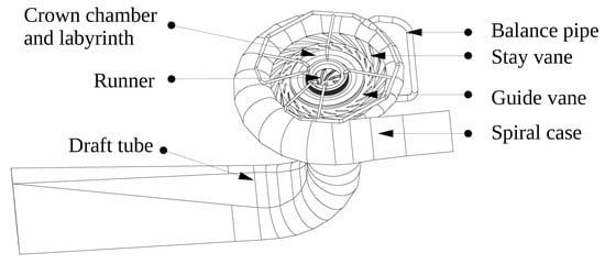
Figure 1.
Flow domain model of the studied RPT unit.
Figure 2 shows the finite volume model (FVM) of the flow domain of the RPT unit with high-quality structured and unstructured meshes. The near-wall meshes of the runner, the guide vanes, etc. are refined to predict the turbulent flow accurately. The inlet and outlet boundaries are also shown in Figure 2.

Figure 2.
Mesh of the studied RPT unit.
The pressure pulsation and the RSI-induced stress at the full load in generation mode must be below allowable values, so the full load with the head of 440 m was selected to perform the unsteady CFD analysis. The runner flow passage was in the rotating frame rated at 375 rpm, while the other low passages were in a stationary frame. The interfaces between the runner flow passage and the stationary passages are specified as transient rotor–stator interfaces, and there was no relative motion at the interfaces between the various stationary fluid domains. The boundary conditions of the spiral case inlet and the draft tube were specified as total pressure and static pressure, respectively. All surfaces except the domain interfaces and inlet and outlet boundary conditions were set to non-slip wall conditions. In order to ensure that the CFD calculation convergence, the total simulation time was set as 1.6 s, corresponding to 10 rotating revolutions. For the flow analysis, 720 time steps per rotating revolution were applied to capture the important frequency components of the RSI pressure pulsations. A high-resolution solver was used for the CFD analysis with the residual target .
4. Results and Discussion
The pressure distribution of the prototype RPT unit under the full load is shown in Figure 3. It can be seen from the inlet of the spiral case to the outlet of the draft tube that the pressure decreases gradually. The flow velocity distribution of the unit is demonstrated in Figure 4. It shows that from the spiral case to the draft tube the flow velocity is quite smooth and stable. Compared to other flow passages, the flow velocity in the runner passage is larger.
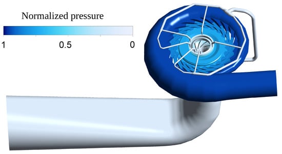
Figure 3.
Pressure distribution of the RPT unit.

Figure 4.
Flow velocity distribution of the RPT unit.
The rotating RPT runner in turbine mode cuts off the guide vane downstream flow and produces periodic pressure pulsations in the vaneless space. This RSI-induced pressure pulsation may cause strong vibrations and dynamic stresses in the pump–turbine runner. The frequency of the RSI-induced pressure pulsation on the runner is related to the rotating frequency and the number of guide vanes of the unit. The rotating frequency () of the investigated prototype RPT unit was 6.25 Hz, and the guide vane number () was 22, so the excitation frequency of the RSI-induced pressure pulsation observed on the runner can be calculated as follows [12]:
The pressure pulsation excitation frequency (137.5 Hz) was around 22% different from the natural frequency (167 Hz) of the runner in water and does not cause resonance in the runner during operation.
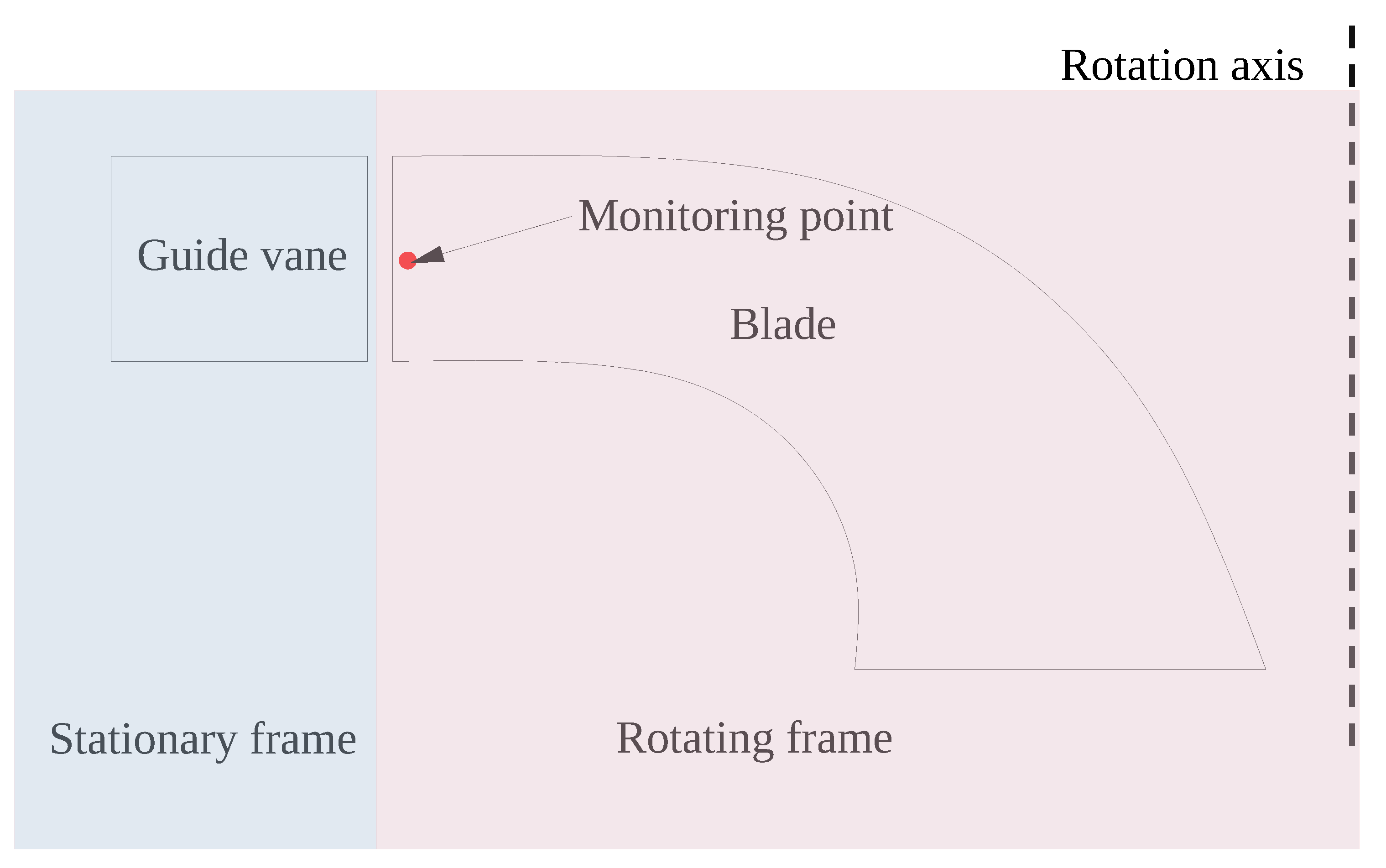
The settled monitoring point in the rotating frame is close to the leading edge of a runner blade (Figure 5), and it can provide the RSI-induced pressure pulsation characteristics to the turbine runner.
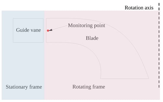
Figure 5.
The location of the pressure monitoring point in the rotating frame.
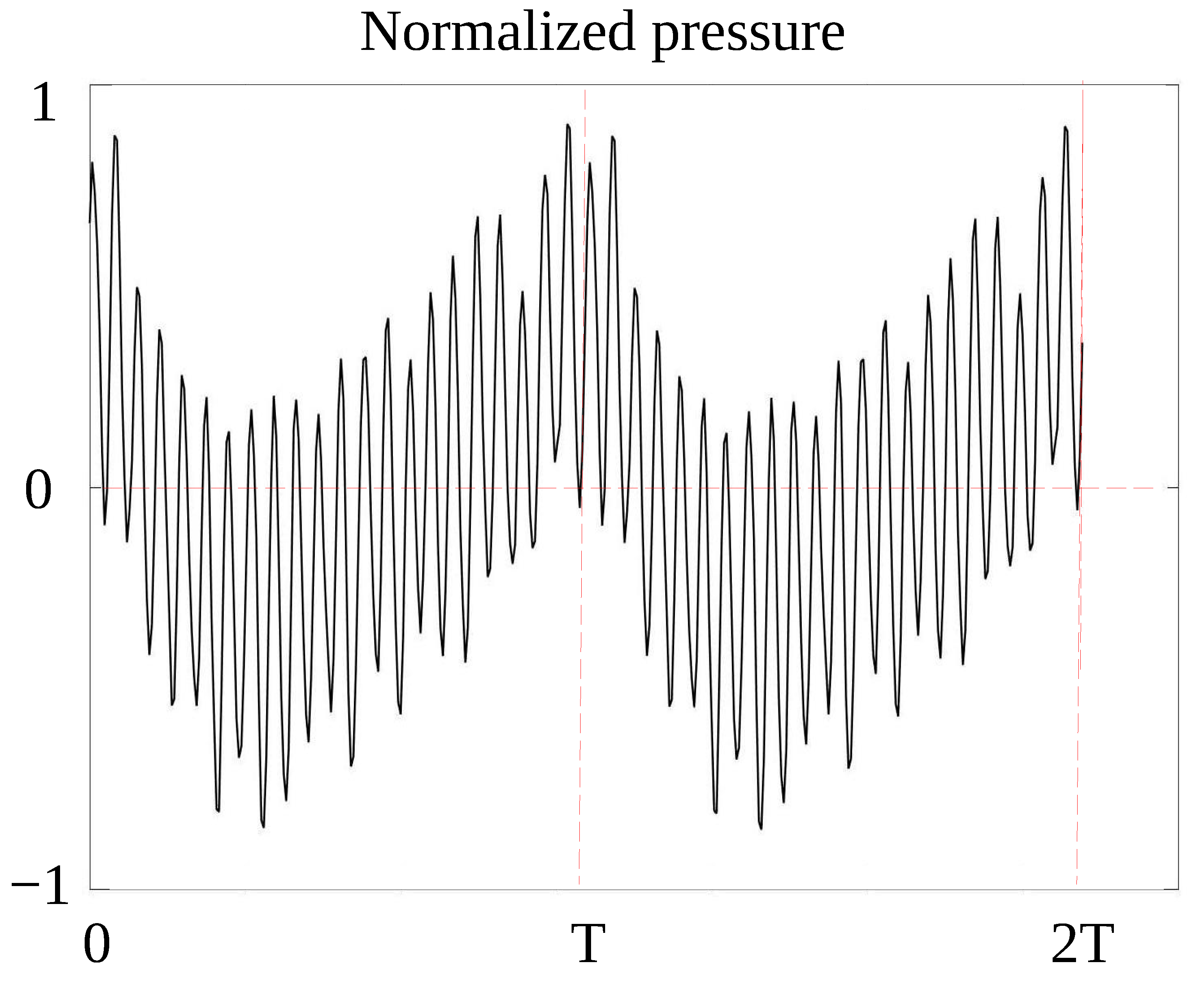
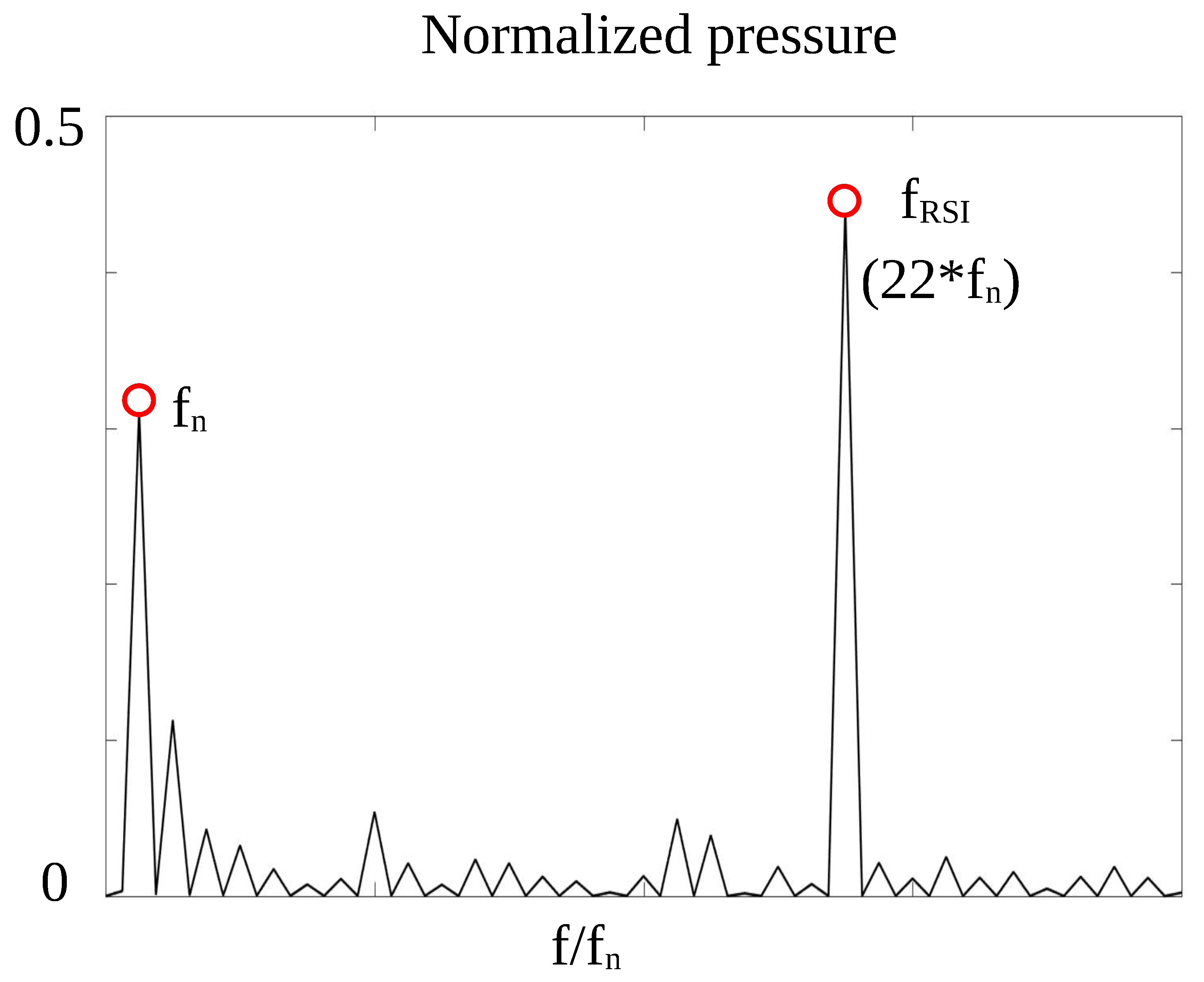
The time domain signal of the pressure monitoring point for the last two revolutions from the CFD simulation is presented in Figure 6. The corresponding frequency spectrum of the time domain signal is shown in Figure 7. The pressure pulsation has high-pressure pulsation peaks at the rotating frequency () of 6.25 Hz and the guide vane passing frequency () of 137.5 Hz.
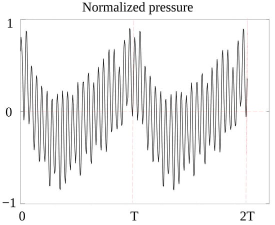
Figure 6.
Timedomain signal of the pressure monitoring point.
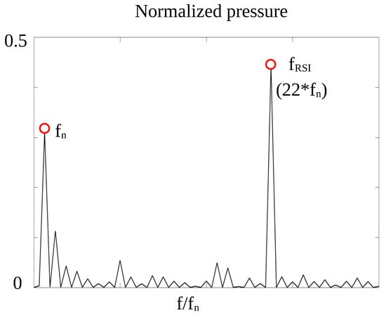
Figure 7.
Frequency domain signal of the pressure monitoring point.
5. Transient Flow-Induced Dynamic Stress Analysis of the RPT Runner
In this study, the full-scale 3D CAD model of the RPT runner was built, and the FE mesh of the runner is shown in Figure 8. The mesh at the fillets of a runner blade was refined to have an accurate result.
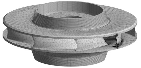
Figure 8.
FE mesh of the RPT runner.
The dynamic stress distributions of the runner at the rotating frequency () and the guide vane passing frequency () are shown in Figure 9 and Figure 10, respectively.
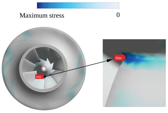
Figure 9.
Dynamic stress distribution of the RPT runner at (6.5 Hz).
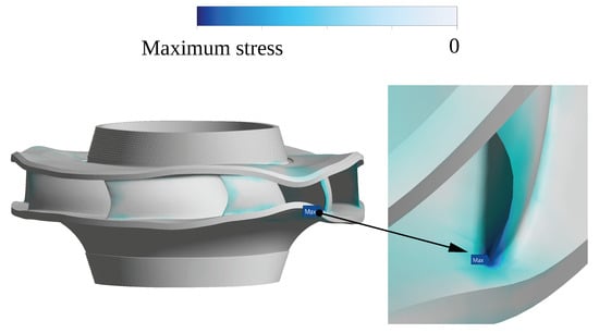
Figure 10.
Dynamic stress distribution of the RPT runner at (137.5 Hz).
The results show that the maximum dynamic stress (0.1 MPa) of the runner under the excitation of the rotating frequency () of 6.5 Hz is located at the junction between the blade trailing edge and the crown, and the maximum dynamic stress (1.8 MPa) of the runner under the excitation of a guide vane passing frequency () of 137.5 Hz is at the junction between the blade leading edge and the band. The total maximum dynamic stress is less than 2 MPa, which is much lower than the allowable value of the runner material.
6. Conclusions
In this study, the CAD models of the fluid passages, from the spiral case to the draft tube, and the runner structure of a high-head prototype pump–turbine unit were constructed. The transient CFD analysis results and transient flow-induced stresses of the pump–turbine were obtained.
The pressure distribution and flow velocity distribution of the pump–turbine unit at full load were investigated. The pressure from the spiral case to the draft tube decreases gradually. The flow velocity in the flow passage of the pump–turbine unit is smooth and stable. The flow velocity in the runner domain is larger than in other domains, but no strong vortex appears in the draft tube.
The pressure monitoring signal in the runner flow passage was evaluated in the time and frequency domains. The dominant frequency of the RSI-induced pressure pulsation acting on the runner is the guide vane passing frequency.
The pressure results obtained through the CFD simulation at full load were adopted to perform the transient flow-induced stresses analysis of the pump–turbine runner.
The maximum dynamic stress of the runner under the excitation of the rotating frequency () of 6.5 Hz was 0.1 MPa, which is located at the junction between the blade trailing edge and the crown; the maximum dynamic stress of the runner under the excitation of the guide vane passing frequency () of 137.5 Hz was 1.8 MPa, which is located at the junction between the blade leading edge and the band. The total maximum dynamic stress was below 2 MPa, which is much lower than the allowable value of the pump–turbine runner.
The calculation approach presented in this study and the obtained conclusions can be used as a reference to evaluate the designs of other high-head pump–turbine units. It can also be generalized to other types of fluid turbomachinery, such as pumps, turbines, turbo engines, compressors, fans, turbochargers, etc.
Author Contributions
Conceptualization, Z.W. and X.H.; methodology, X.H.; analysis, D.Z., Q.Q. and X.H.; validation, B.W. and Y.X.; investigation, D.Z., Q.Q. and X.H.; writing—original draft preparation, D.Z., Q.Q. and X.H.; writing—review and editing, X.H., B.W. and Y.X.; supervision, Z.W. All authors have read and agreed to the published version of the manuscript.
Funding
The technological research project funding from State Grid Xinyuan Holdings Co., Ltd.: “Research and application technical service of safety prediction and evaluation system for transient dynamic characteristics of pumped storage units of Zhen’an Company”.
Data Availability Statement
Data are contained within the article.
Acknowledgments
The authors gratefully acknowledge the State Grid Xinyuan Holdings Co., Ltd.
Conflicts of Interest
Authors Dehao Zhang, Qiang Quan, Biao Wang and Yunfeng Xiao were employed by the company Shannxi Zhen’an Pumped Storage Co., Ltd. The remaining authors declare that the research was conducted in the absence of any commercial or financial relationships that could be construed as a potential conflict of interest.
Abbreviations
The following abbreviations are used in this manuscript:
| CFD | computational fluid dynamics; |
| FE | finite element; |
| FSI | fluid–structure interaction; |
| FVM | finite volume method; |
| PSPS | pumped-storage power station; |
| RPT | reversible pump–turbine; |
| RSI | rotor–stator interaction; |
| SST | shear stress transport. |
References
- Ambec, S.; Crampes, C. Electricity provision with intermittent sources of energy. Resour. Energy Econ. 2012, 34, 319–336. [Google Scholar] [CrossRef]
- Widén, J.; Carpman, N.; Castellucci, V.; Lingfors, D.; Olauson, J.; Remouit, F.; Bergkvist, M.; Grabbe, M.; Waters, R. Variability assessment and forecasting of renewables: A review for solar, wind, wave and tidal resources. Renew. Sustain. Energy Rev. 2015, 44, 356–375. [Google Scholar] [CrossRef]
- Pommeret, A.; Schubert, K. Optimal energy transition with variable and intermittent renewable electricity generation. J. Econ. Dyn. Control 2022, 134, 104273. [Google Scholar] [CrossRef]
- Rehman, S.; Al-Hadhrami, L.M.; Alam, M.M. Pumped hydro energy storage system: A technological review. Renew. Sustain. Energy Rev. 2015, 44, 586–598. [Google Scholar] [CrossRef]
- Diawuo, F.; Kabo-bah, A.T.; Ofosu, E. Pumped Hydro Energy Storage for Hybrid Systems; Elsevier: Amsterdam, The Netherlands, 2022. [Google Scholar]
- Stelzer, R.S.; Walters, R.N. Estimating Reversible Pump-Turbine Characteristics; United States Department of the Interior Bureau of Reclamation: Denver, CO, USA, 1977.
- Franke, G.F.; Fisher, R.K.; Hydro, V.S.; Seidel, U.; Koutník, J. On Pressure Mode Shapes Arising from Rotor/Stator Interactions. Sound Vib. 2005, 39, 14–18. [Google Scholar]
- Ciocan, G.D.; Kueny, J.L. Experimental Analysis of Rotor-Stator interaction in a Pump-Turbine. In Proceedings of the 23rd IAHR Symposium on Hydraulic Machinery and Systems, Yokohama, Japan, 17–21 October 2006. [Google Scholar]
- Nicolet, C.; Ruchonnet, N.; Alligné, S.; Koutnik, J.; Avellan, F. Hydroacoustic simulation of rotor-stator interaction in resonance conditions in Francis pump-turbine. Iop Conf. Ser. Earth Environ. Sci. 2010, 12, 012005. [Google Scholar] [CrossRef]
- Yang, H.; He, Q.; Huang, X.; Yang, M.; Bi, H.; Wang, Z. Experimental and Numerical Investigation of Rotor–Stator Interaction in a Large Prototype Pump–Turbine in Turbine Mode. Energies 2022, 15, 5523. [Google Scholar] [CrossRef]
- Peltier, R.; Boyko, A.L.; Popov, S.; Krajisnik, N. Investigating the Sayano-Shushenskaya Hydro Power Plant Disaster. Power 2010, 154, 48. [Google Scholar]
- Egusquiza, E.; Valero, C.; Huang, X.; Jou, E.; Guardo, A.; Rodríguez, C.G. Failure investigation of a large pump-turbine runner. Eng. Fail. Anal. 2012, 23, 27–34. [Google Scholar] [CrossRef]
- Huang, X.; Chamberland-Lauzon, J.; Oram, C.; Klopfer, A.; Ruchonnet, N. Fatigue analyses of the prototype Francis runners based on site measurements and simulations. Iop Conf. Ser. Earth Environ. Sci. 2014, 22, 012014. [Google Scholar] [CrossRef]
- Stosiak, M.; Karpenko, M.; Prentkovskis, O.; Deptuła, A.; Skačkauskas, P. Research of vibrations effect on hydraulic valves in military vehicles. Def. Technol. 2023, 30, 111–125. [Google Scholar] [CrossRef]
- Stosiak, M. The impact of hydraulic systems on the human being and the environment. J. Theor. Appl. Mech. 2015, 53, 409–420. [Google Scholar] [CrossRef]
- Ru, S.; Zhang, S.; Zhou, K.; Huang, X.; Huang, W.; Wang, Z. Numerical Study on the Flow and Structural Characteristics of a Large High Head Prototype Pump-Turbine under Different Operating Conditions. Processes 2023, 11, 2970. [Google Scholar] [CrossRef]
- Stosiak, M.; Karpenko, M. Dynamics of Machines and Hydraulic Systems: Mechanical Vibrations and Pressure Pulsations; Synthesis Lectures on Mechanical Engineering; Springer Nature Switzerland: Berlin/Heidelberg, Germany, 2024. [Google Scholar]
- Dring, R.P.; Joslyn, H.D.; Hardin, L.W.; Wagner, J.H. Turbine Rotor-Stator Interaction. J. Eng. Power 1982, 104, 729–742. [Google Scholar] [CrossRef]
- Nicolet, C.; Ruchonnet, N.; Avellan, F. One-Dimensional Modeling of Rotor Stator Interaction in Francis Pump-Turbine. In Proceedings of the 11th International Symposium on Transport Phenomena and Dynamics of Rotating Machinery, ISROMAC-11, Yokohama, Japan, 18–21 October 2006; Volume 2. [Google Scholar]
- Hasmatuchi, V. Hydrodynamics of a Pump-Turbine Operating at Off-Design Conditions in Generating Mode; Technical Report; EPFL: Lausanne, Switzerland, 2012. [Google Scholar]
- Zobeiri, A.; Kueny, J.L.; Farhat, M.; Avellan, F. Pump-turbine rotor-stator interactions in generating mode: Pressure fluctuation in distributor channel. In Proceedings of the 23rd IAHR Symposium on Hydraulic Machinery and Systems, Yokohama, Japan, 17–21 October 2006; Volume 1, pp. 1–10. [Google Scholar]
- Ke, W.; Zeng, H.; Wang, Z.; Yu, H.; Liu, Y.; Zheng, D.; Zhu, J.; Zhu, H. A Numerical Study on Labyrinth Screw Pump (LSP) Performance under Viscous Fluid Flow. Energies 2023, 16, 5997. [Google Scholar] [CrossRef]
- Liu, Y.; Ozbayoglu, E.M.; Upchurch, E.R.; Baldino, S. Computational fluid dynamics simulations of Taylor bubbles rising in vertical and inclined concentric annuli. Int. J. Multiph. Flow 2023, 159, 104333. [Google Scholar] [CrossRef]
- Liu, Y.; Mitchell, T.; Upchurch, E.R.; Ozbayoglu, E.M.; Baldino, S. Investigation of Taylor bubble dynamics in annular conduits with counter-current flow. Int. J. Multiph. Flow 2024, 170, 104626. [Google Scholar] [CrossRef]
- Wang, Z.; Yang, J.; Wang, W.; Qu, J.; Huang, X.; Zhao, W. Research on the Flow-Induced Stress Characteristics of Head-Cover Bolts of a Pump-Turbine during Turbine Start-Up. Energies 2022, 15, 1832. [Google Scholar] [CrossRef]
- He, Q.; Huang, X.; Yang, M.; Yang, H.; Bi, H.; Wang, Z. Fluid–Structure Coupling Analysis of the Stationary Structures of a Prototype Pump Turbine during Load Rejection. Energies 2022, 15, 3764. [Google Scholar] [CrossRef]
- Yin, X.; Huang, X.; Zhang, S.; Bi, H.; Wang, Z. Numerical Investigation of Flow and Structural Characteristics of a Large High-Head Prototype Pump–Turbine during Turbine Start-Up. Energies 2023, 16, 3743. [Google Scholar] [CrossRef]
- Lais, S.; Liang, Q.; Henggeler, U.; Weiss, T.; Escaler, X.; Egusquiza, E. Dynamic Analysis of Francis Runners - Experiment and Numerical Simulation. Int. J. Fluid Mach. Syst. 2009, 2, 303–314. [Google Scholar] [CrossRef]
- Seidel, U.; Hübner, B.; Löfflad, J.; Faigle, P. Evaluation of RSI-induced stresses in Francis runners. Iop Conf. Ser. Earth Environ. Sci. 2012, 15, 052010. [Google Scholar] [CrossRef]
- Tanaka, H. Vibration Behavior and Dynamic Stress of Runners of Very High Head Reversible Pump-turbines. Int. J. Fluid Mach. Syst. 2011, 4, 289–306. [Google Scholar] [CrossRef]


Disclaimer/Publisher’s Note: The statements, opinions and data contained in all publications are solely those of the individual author(s) and contributor(s) and not of MDPI and/or the editor(s). MDPI and/or the editor(s) disclaim responsibility for any injury to people or property resulting from any ideas, methods, instructions or products referred to in the content. |
© 2024 by the authors. Licensee MDPI, Basel, Switzerland. This article is an open access article distributed under the terms and conditions of the Creative Commons Attribution (CC BY) license (https://creativecommons.org/licenses/by/4.0/).