Article

Experimental Study on the Heat Pump Performance Combined with Dual-Purpose Solar Collector

1
Graduate School of Refrigeration and Air-Conditioning Engineering, Pukyong National University, Busan 48513, Republic of Korea
2
Department of Refrigeration and Air-Conditioning Engineering, Chonnam National University, Yeosu 59626, Republic of Korea
3
Department of Refrigeration and Air-Conditioning Engineering, Pukyong National University, Busan 48513, Republic of Korea
*
Author to whom correspondence should be addressed.
Energies 2024, 17(12), 3038; https://doi.org/10.3390/en17123038
Submission received: 3 June 2024 / Revised: 15 June 2024 / Accepted: 17 June 2024 / Published: 20 June 2024
(This article belongs to the Special Issue Recent Developments in Solar Thermal Energy)

Abstract

:
In this study, we proposed and experimentally investigated a novel solar-assisted heat pump (SAHP) system integrated with a dual-purpose solar collector (DPSC). The DPSC is a solar collector designed to produce both heated air and hot water, and the proposed configuration of the SAHP utilizes both heated air and water simultaneously to improve the performance of the heat pump. The experiment was conducted under natural weather conditions on a clear day. The performance of the proposed system was evaluated and compared to that of a conventional air-type SAHP system. The results showed that the coefficient of performance (COP) of the proposed system, which takes into account the performance of the DPSC, heat pump, and the power consumption of both the blower and pump, was 3.14. In contrast, the system COP of the SAHP operated as conventional air-type SAHP was 2.33. This finding clearly demonstrated that the proposed SAHP performed better than the traditional SAHP mode. Additionally, the results of this research are useful as fundamental data related to SAHP combined with DPSC.

1. Introduction

In response to global warming, environmental concerns, and energy resource constraints, concerted efforts are being made to utilize renewable energy sources. Buildings, in particular, account for approximately 40% of global energy consumption, making it imperative to focus on reducing this significant share [1]. Solar energy is an abundant energy source that can reduce the consumption of primary energy resources such as fossil fuels. A solar collector is a device that produces heat energy from solar energy, and is divided into liquid type and air type depending on the working fluid. However, solar collectors have disadvantages. The thermal efficiency of liquid-type solar collectors decreases when the inlet water temperature increases. Additionally, air-type solar collectors exhibit low thermal efficiency and lack the capability to store heat. A dual-purpose solar collector (DPSC) has been proposed to address these limitations. The DPSC provides higher thermal performance than conventional solar collectors by allowing air to recover heat loss at the absorber. Moreover, it can heat either air or water individually, making it applicable in various fields.
Assari et al. [2] developed and analyzed numerical models of DPSC featuring air channels with various geometrical configurations, utilizing the ε-NTU method. Their research indicated that DPSCs with rectangular fins had better heat transfer performance than DPSCs without fins. Additionally, it was demonstrated that heat not obtained by water could be effectively recovered via air instead of dissipating to the ambient. Mohajer et al. [3] investigated the performance of a food dryer that included a DPSC. This system uses heated air to dry the food and stored hot water for domestic purposes. The study revealed that integrating DPSC with a drying system could reduce installation costs and space requirements by 50% compared to the drying system using traditional air or water solar collectors. Nematollahi et al. [4] investigated the thermal performance of a DPSC equipped with a triangular fin at different airflow rates. The results demonstrated that the DPSC was more efficient than a single-purpose solar collector (SPSC). This study further revealed that maintaining the inflow-water temperature at a low value enhanced the DPSC’s efficiency. Zhang et al. [5] investigated the thermal performance of DPSC according to individual or simultaneous operation of working fluids based on the mathematical model. Their research showed that the average thermal efficiency was 51.3% and 51.4% when the air or water heated individually, while the efficiency reached 73.4% when the air and water heated simultaneously. Hu et al. [6] evaluated a roof-type DPSC with wave design, comparing it with different types of roof DPSC. The proposed DPSC exhibited up to 65.3% lower thermal loss compared to other solar collectors. They indicated that the roof DPSC could serve as a foundational reference for the design and application of building-integrated solar collectors. Hao et al. [7] conducted experimental and numerical studies on the DPSC for agricultural drying. They demonstrated superior thermal efficiency under conditions that simultaneously heated both air and water compared to heating only air or water. They emphasized that this approach could maximize solar energy utilization and improve the quality of the dried products. Jinwei et al. [8] conducted an experimental and mathematical study on the passive heating of buildings integrated with DPSC. They highlighted that the thermal efficiency of the DPSC was 44.3%, which is superior to that of traditional passive solar air collectors. Additionally, they revealed that heating the air through the DPSC can reduce heating loads and decrease power consumption. Pathak et al. [9,10] conducted an experimental study on SPSC and DPSC with corrugated plates to analyze their performances with various flow rates of the working fluid. They found that the performance of DPSC with corrugated plates improved by 16.74% compared to single-purpose solar collectors. Shemelin and Matuska et al. [11] presented three alternative system configurations to analyze potential applications of DPSC for buildings and compared annual energy production under different weather conditions. As a result, when air and water were heated simultaneously, production was confirmed to be up to 30% higher compared to conventional solar domestic water heating systems. Additionally, they revealed that combining a DPSC system with heat recovery can reduce potential heat consumption. Somwanshi and Sarkar [12] presented a novel DPSC design with a built-in storage tank and developed its mathematical model. Based on this mathematical model, the heat collection performance was compared and analyzed according to air flow rate. As a result, the maximum and average thermal efficiencies were found to be 82.81% and 76%, respectively, which is higher than SPSC. Excluding this research, various studies related to DPSC were investigated through review papers [13].
However, solar collectors such as DPSCs have the temperature level is low for space heating or supplying hot water to buildings. Therefore, many studies have been conducted on heat pumps combined with solar collectors, known as solar-assisted heat pumps (SAHPs). SAHP systems utilize heated air or water as a heat source for the evaporation of refrigerant. Consequently, the evaporation temperature of the heat pump rises, resulting in a higher coefficient of performance (COP).
Comakli et al. [14] performed fundamental research on improving the performance of heat pump systems using solar energy as an auxiliary heat source and proved an increase in heat pump performance. Li et al. [15] conducted energy and exergy analyses of an SAHP. Their findings revealed that the energy consumption for heating and cooling was significantly reduced by incorporating solar thermal energy as an auxiliary heat source in heat pump systems. Dikici et al. [16] performed experimental studies to analyze the energy and exergy performance of an SAHP system. Their findings indicated a decrease in exergy loss at an evaporator by the solar energy could enhance the COP of a heat pump. Wang et al. [17] demonstrated that the SAHP can operate in multiple energy-saving modes, including air conditioning, space heating, and domestic hot water production, with seamless mode transitions. The experimental results indicate that the system can provide hot water with less electricity than solar water heaters on cloudy days. Additionally, it outperformed conventional residential heat pumps during the cold winter season. Fernandez-Seara et al. [18] conducted an experimental study to assess the performance of an SAHP for water heating under zero irradiation conditions. The system had a COP of 3.22 when the temperature differential between water and ambient air was 15 °C, confirming its efficiency in heating water even in the absence of solar radiation. Liu et al. [19] explored a solar-air composite heat source SAHP and designed a dual heat source composite heat exchanger capable of utilizing solar hot water and ambient air separately or simultaneously. System performance was analyzed with various working fluids and ambient air temperatures. The results demonstrated that the heat gain and the COP were more than 50% higher than those of a conventional air source heat pump system, particularly under low ambient air temperatures. Hematian et al. [20] utilized an SAHP system to heat a semi-solar greenhouse and assessed the internal temperature variations with various operating conditions. The study found that increased irradiation and ambient temperature improved both the collection efficiency and system COP. Conversely, higher condensing temperatures and compressor velocities were found to negatively affect the COP. Singh et al. [21] proposed an SAHP dryer and investigated the effects of incident solar irradiance on the energy, exergy, economic, and exergoeconomic performance of the proposed system. Their findings revealed that despite the higher costs associated with additional system components, the SAHP dryer was recommended due to its lower energy consumption and superior drying performance. Sharaborova et al. [22] investigated the dynamic characteristics of an SAHP by integrating ejector technology to improve the heat pump performance. According to this study, including an ejector significantly improves the system performance by optimizing the refrigerant cycle. Choi and Choi [23,24] experimentally investigated the impact of an air-type PVT with a triangular obstacle on the performance of a heat pump. Additionally, based on the verified results and the energy balance equation, they established a mathematical model to analyze the performance under various parameters. As a result, the proposed heat pump showed up to a 13.28% higher COP compared to an air-source heat pump (ASHP). Their research confirmed the feasibility of an SAHP combined with PVTAH. Wu et al. [25] conducted a study on a heat pump system using solar and air sources. To evaluate the heating performance and economic benefits of the system, they compared and analyzed it with an air-source heat pump and a solar-electric auxiliary heating system. As a result, both the heating COP and economic benefits were superior. They revealed that this system could expand the feasibility of utilization in high-cold regions.
However, previous studies on SAHP systems have limitations, as they are combined with only single-purpose solar collectors. Furthermore, there is little research on heating and cooling systems integrated with DPSC. This is what motivates us to conduct the research.
Therefore, in this study, we proposed an SAHP system combined with a DPSC and experimentally evaluated. DPSC can produce heated air and water simultaneously or individually. Heated air increases the evaporation temperature, improving system performance. Additionally, hot water contributes to reducing the heat required by the condenser. The objective of this research is to confirm the feasibility of the proposed system. Thus, this study fabricated an SAHP system combined with a DPSC and conducted experiments under real weather conditions. Additionally, to evaluate the performance improvement of a system using DPSC, the traditional SAHP using heated air is evaluated and compared with the performance of the proposed system.

2. Experimental Apparatus and Methods

2.1. Experimental Apparatus

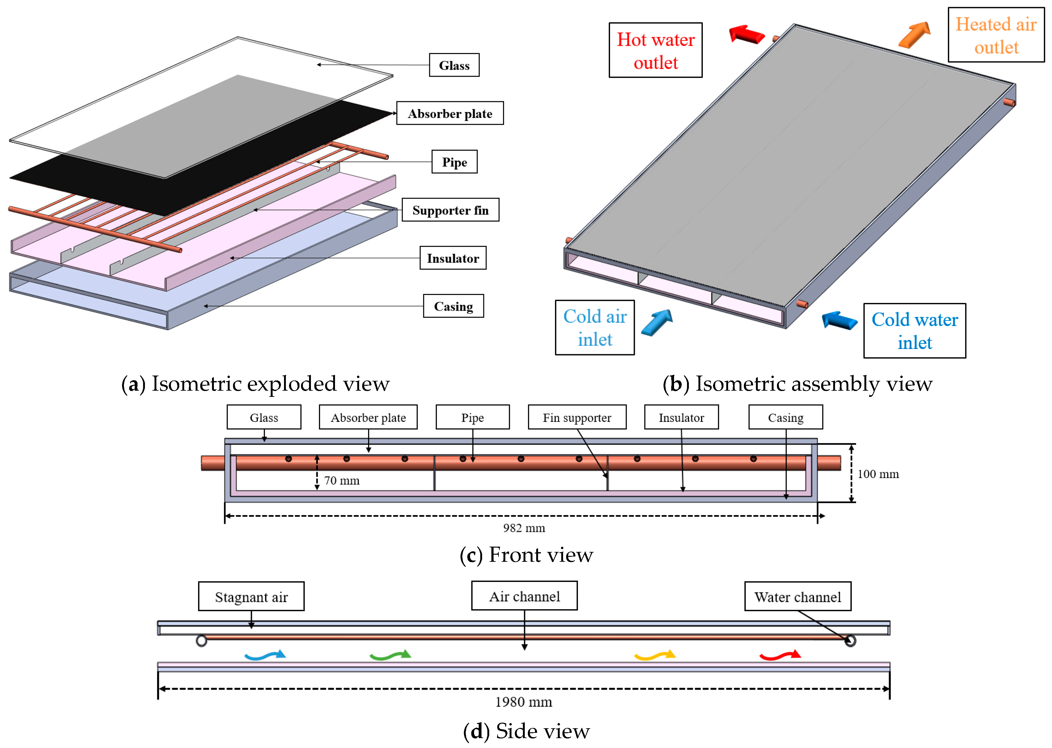
2.1.1. Dual-Purpose Solar Collector

Figure 1 presents the schematic diagram of the proposed system’s DPSC. The DPSC is a modified version of the conventional liquid-type solar collector and consists of glass, an absorber plate, fin supporters, insulator, and casing. There is a stagnant air layer between the absorber plate and the glass, which prevents heat loss to the top. Solar energy transmitted through the glass reaches the absorber plate and is converted into thermal energy. Beneath the absorber plate, there is a water tube and an air channel, where air and water can be heated simultaneously or individually. In simultaneous heating mode, both the water tube and air channels are open. However, if the operating mode is air heating, air flows through the air channels while the water tube is closed at the inlet and outlet. This system can also heat only the water by closing the inlet and outlet of the air channels. Fin supporters are installed in the air channel to improve the heat transfer area and prevent sagging of the absorber plate and water tube. The insulator is installed at the sides and bottom of the air channel to reduce heat loss from the DPSC to the surroundings. More detailed specifications of the DPSC are provided in Table 1.

2.1.2. Heat Pump

The heat pump system consists of a compressor, condenser, capillary tube, and evaporator. The refrigerant compressed in the compressor enters the condenser as high-temperature and high-pressure vapor. In the condenser, the refrigerant vapor exchanges heat with the water preheated by the DPSC, and the refrigerant enters the capillary tube in a subcooled state after releasing heat to the water. At this time, the water that has absorbed heat from the refrigerant flows into the thermal storage tank. The subcooled refrigerant undergoes a throttling process in the capillary tube, entering the evaporator as a low-temperature and low-pressure liquid. The evaporator is a fin-tube heat exchanger where the refrigerant liquid exchanges heat with the air heated by the DPSC. The refrigerant, having acquired heat from the heated air, is drawn into the compressor as a superheated vapor. The refrigerant is R410A, and the compressor (Rechi, 39A172A, Taiwan) is used in the proposed system. More detailed specification of the heat pump’s components is listed in Table 2.

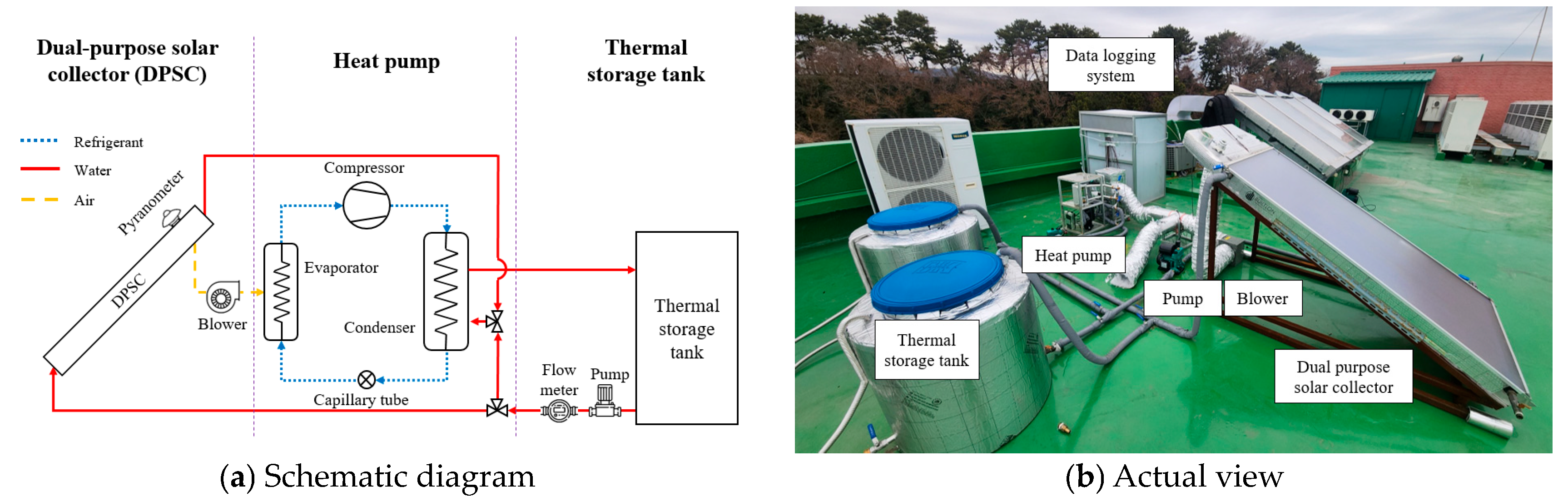
2.1.3. Solar-Assisted Heat Pump Combined with DPSC

Figure 2 shows a schematic diagram and an actual view of the proposed SAHP. The system consists of a DPSC, heat pump, and thermal storage tank. The proposed SAHP system aims to improve the heating performance. The heated air from the DPSC is supplied to the evaporator in the SAHP, increasing the evaporation temperature. In addition, the preheated water flows through the condenser into the thermal storage tank.

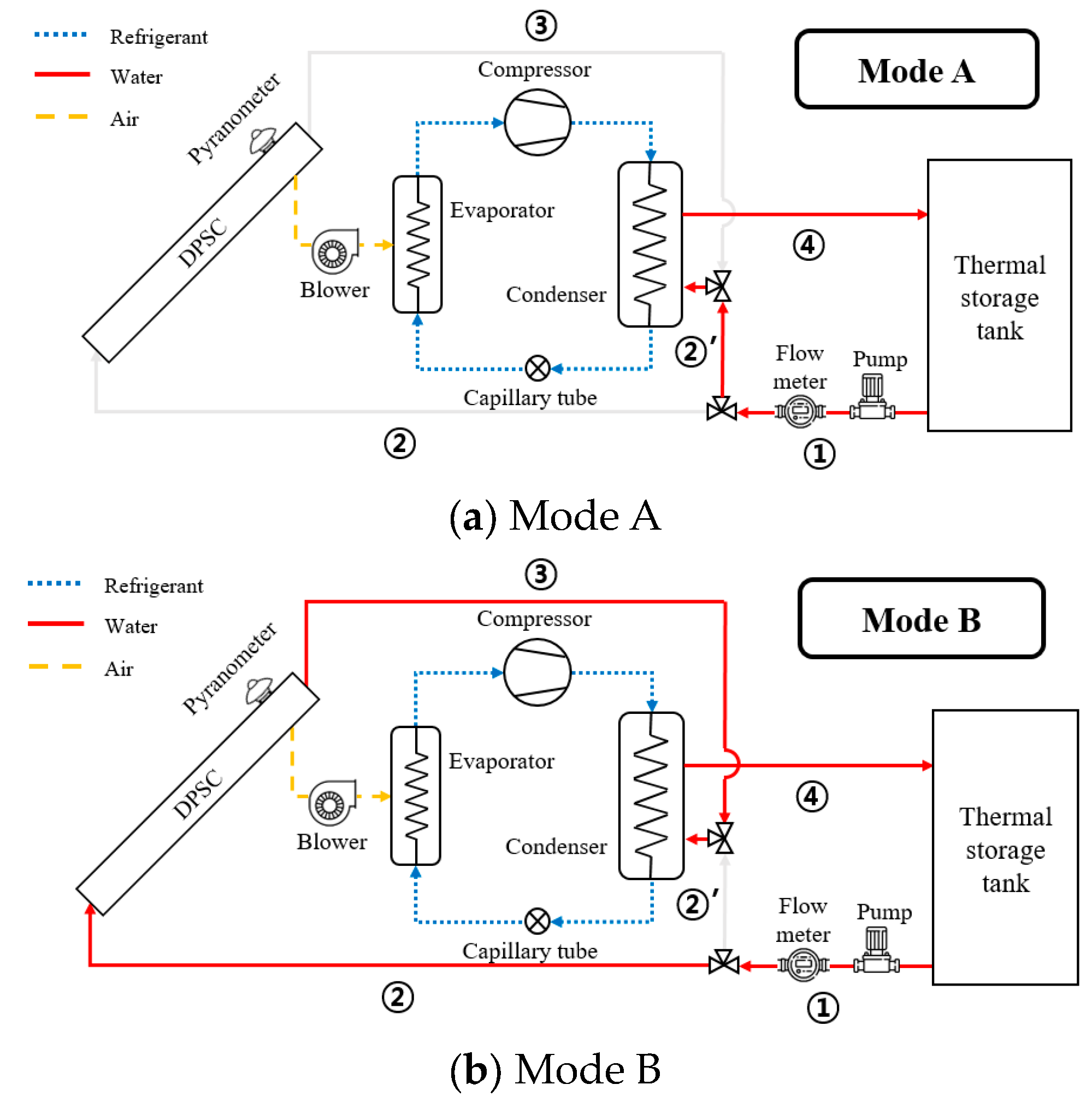
2.2. Experimental Procedure

Figure 3 illustrates the two different operation modes of the proposed system. In both modes A and B, the heated air is directed to the heat pump evaporator. However, in Mode B (1→2→3→4), the water flows through the DPSC to the condenser, whereas in Mode A (1→2′→4), the water flows directly to the condenser. The experiments were conducted on different days for each mode from 10:00 to 14:00. The air and water flow rates were 0.05 kg/s and 0.0635 kg/s, respectively. A pyranometer was used to measure the solar radiation. The temperatures were measured by T-type thermocouples. Air velocity and water flow rate were obtained by the anemometer and flowmeter, respectively. A power meter was used to measure the power consumption of the compressor, pump, and blower. Additionally, all of the measured data were recorded by a data logger. Table 3 summarizes the experimental conditions, and the specifications of the measurement instruments are listed in Table 4.

2.3. Performance Indices

The heat gain of the air and water from the DPSC is calculated by [26]
Q w = m ˙ w C p , w T w , o u t T w , i n
Q a = m ˙ a C p , a T a , o u t T a , i n
Thus, the total heat gain of the DPSC can be defined as [26]
Q D P S C = Q w + Q a
Thermal efficiency is the ratio of the heat gain of the working fluids to the solar radiation. Therefore, the thermal efficiency was calculated by [10]
η w = Q w A c G
η a = Q a A c G
The total thermal efficiency of DPSC is calculated by [10]
η D P S C = Q D P S C A c G = Q w + Q a A c G
The heat obtained from the heat pump condenser can be considered as the water circulating through the condenser. Thus, the heat gain of the condenser is calculated by [23]
Q c o n d = m w C P , w T c o n d , w , o u t T c o n d , w , i n
The heat gain of the proposed system is the sum of the heat obtained by the condenser and DPSC. Therefore, the total heat gain of the proposed system can be defined as
Q s y s = Q c o n d + Q w
The COP of the heat pump system is calculated by [23]
C O P H P = Q c o n d W c o m p
The COP of the proposed system is the total ratio of heat gain to power consumption and it is calculated by [25]
C O P s y s = Q s y s W s y s

3. Results and Discussions

3.1. Weather Conditions

Figure 4 shows the irradiation and ambient temperature for operating modes. Mode A exhibited values ranging from 777.15 W/m2 to 1008.82 W/m2, with a mean daily irradiation of 932.93 W/m2. Irradiation values for Mode B varied from 765.94 W/m2 to 1018.48 W/m2, with an average of 956.43 W/m2. The ambient air temperature for Mode A ranged between 4.99 °C and 10.38 °C, while for Mode B it varied between 4.29 °C and 9.81 °C, with daily averages of 7.83 °C and 7.14 °C, respectively. These data confirm that the experiments were performed under comparable environmental conditions.

3.2. Performance of DPSC

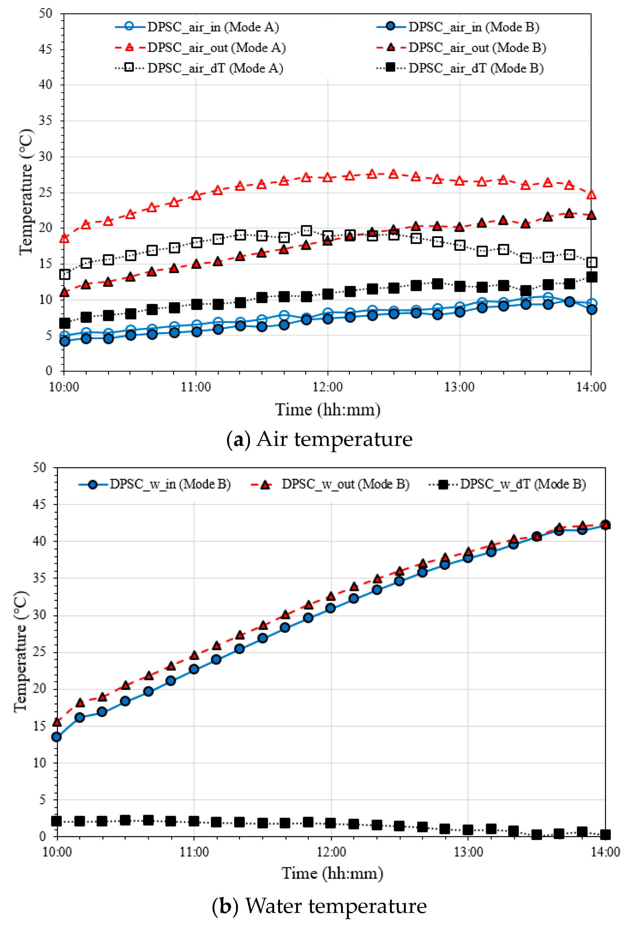
3.2.1. Working Fluid Temperature at DPSC

Figure 5a presents the variation in air temperature at the DPSC. The inlet air temperature matched the ambient air temperature. Mode A exhibited outlet air temperatures ranging from 18.65 °C to 27.63 °C, corresponding to an air temperature increase of 13.66 °C to 19.71 °C. In contrast, Mode B, which simultaneously heats air and water, recorded outlet air temperatures from 11.10 °C to 22.13 °C, with a temperature increase from 6.81 °C to 13.21 °C. This is because energy is distributed between the air and water. Figure 5b shows the water temperature circulating through the DPSC when heating both air and water. The initial water outlet temperature from the DPSC was 13.55 °C, reaching approximately 42.39 °C by the end of the experiment. The temperature difference between the inlet and outlet water ranged from 0.19 °C to 2.23 °C. In addition, the water temperature difference decreases with increasing inlet water temperature because the heat loss at the collector increases with rising water inlet temperature.

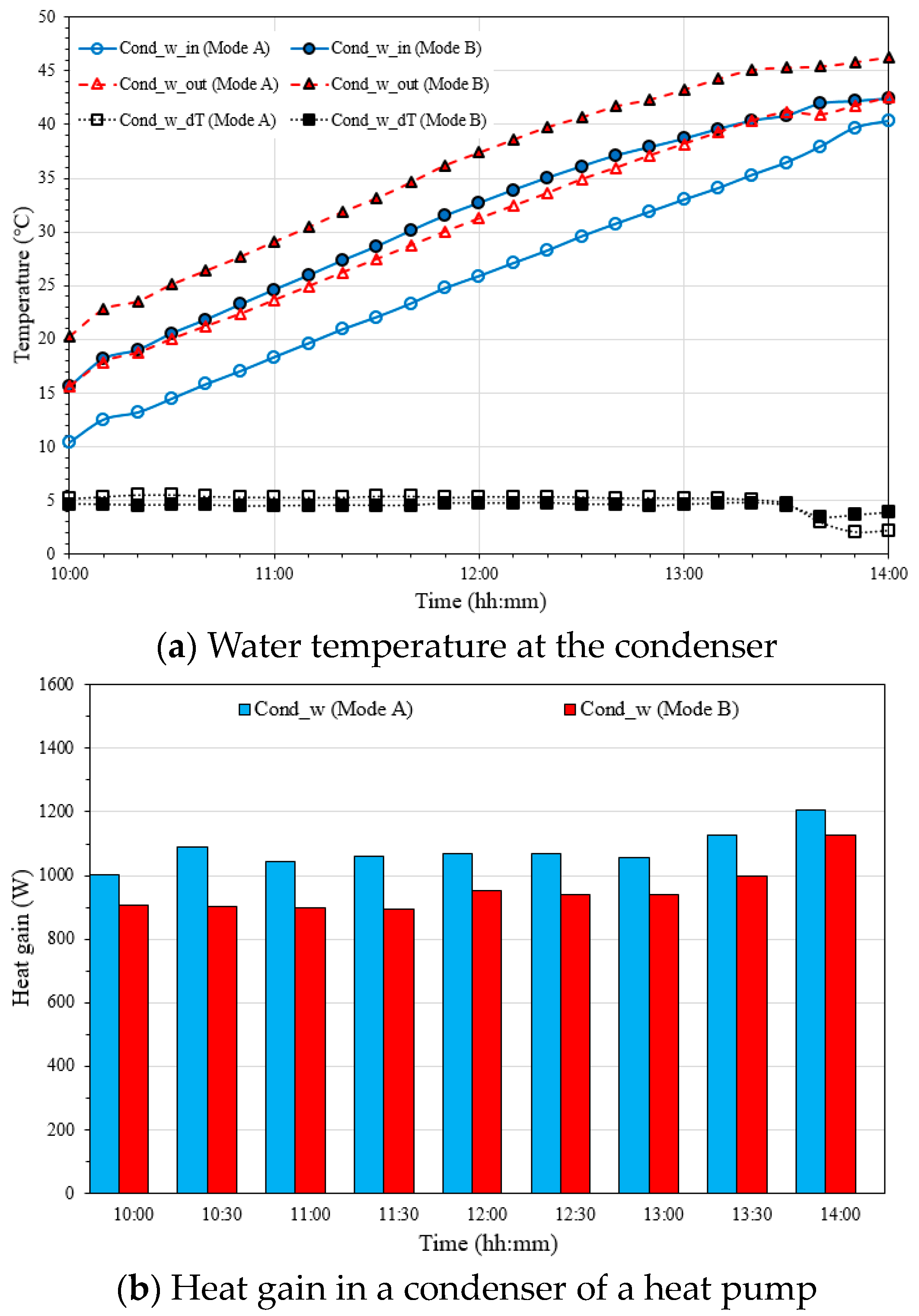
3.2.2. Heat Gain of Fluids

Figure 6 shows the heat gain according to the operation mode. Mode A exhibited heat gains for air between 836.90 W and 1207.93 W. In contrast, in Mode B, the heat gain for air increases from 435.24 W to 844.41 W, while for water it decreases from 427.45 W to 42.65 W. During the operation, the heat gain of water decreased due to the continuous increase in the inlet water temperature. Conversely, the heat gain of air increased with the rising inlet water temperature. This is because the air obtained heat not only from solar irradiance but also from the heated water. Consequently, the total heat gain in Mode B ranged from 762.70 W to 1072.14 W, which was lower compared to Mode A. This is because the increase in inlet water temperature generally leads to higher heat loss from the collector to the ambient environment.

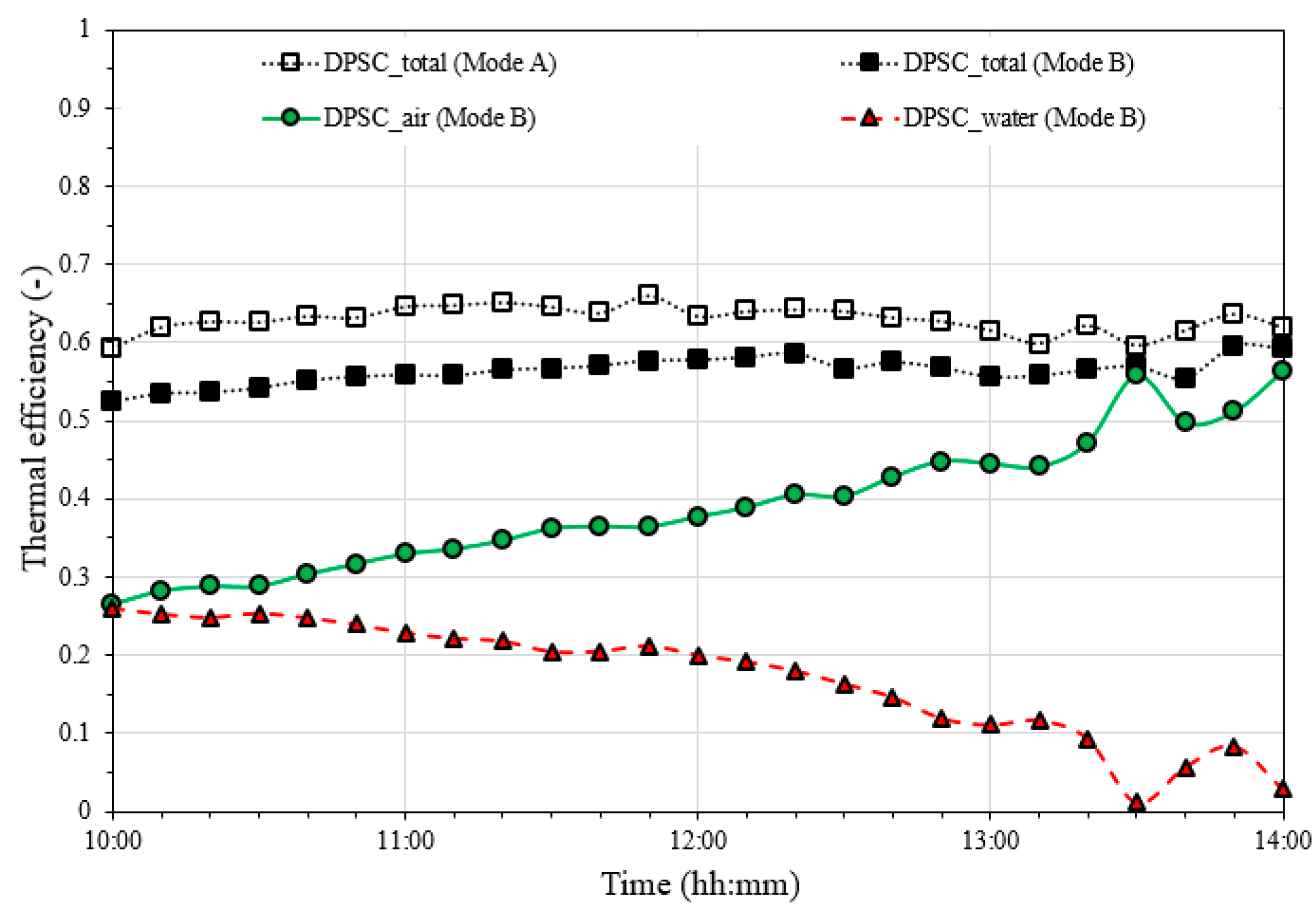
3.2.3. Thermal Efficiency

Figure 7 presents the thermal efficiency of the DPSC for different operating modes. The experimental results showed that the daily average thermal efficiencies for Mode A and Mode B were 62.96% and 56.32%, respectively. At 13:30, solar irradiation suddenly decreases, causing large variations in thermal efficiency on both the air and water sides. However, throughout the entire operation, the thermal efficiency of the air tends to increase continuously, while that of the water continuously decreases. These results confirm that heating only air in the DPSC results in higher thermal efficiency compared to simultaneously heating air and water. This is because the increase in inlet water temperature leads to greater heat loss to the surroundings. Additionally, in Mode B, the thermal efficiency on the air side increased consistently because the air gained heat from both the solar irradiance and the inlet water.

3.3. Performance of the SAHP

3.3.1. Heating Capacity

Figure 8a shows the variation in the water temperature at the condenser. Mode A exhibited a temperature difference between the condenser inlet and outlet of about 5.22 °C. Conversely, Mode B remained approximately at 4.59 °C, which 0.63 °C is lower than Mode A. Figure 8b shows the heat gain in the condenser of a heat pump. Mode A heat gain ranged from 1000.44 W to 1230.61 W, while Mode B’s heat gain ranged from 893.04 W to 1127.16 W. The daily average heat gains were 1078.13 W and 946.62 W, respectively. This difference occurs because the inlet water temperature at the condenser is much higher in Mode B due to the preheating of water by the DPSC.
Figure 9 illustrates the total heat acquired by the water in the proposed system under different modes. Mode A shows the heat gain only from the condenser of the heat pump. However, Mode B includes heat gain from both the heat pump and the DPSC. Thus, the total heat gain in Mode B ranges from 1034.90 W to 1363.03 W. The average total heat gain in Mode B is approximately 16.66% higher compared to Mode A. This confirms that preheating water improves heating performance, despite a reduction in the heat gain from the condenser of the heat pump.
Figure 10 shows the temperature change in the heat storage tank based on the operation method. Mode A starts with an initial water tank temperature of 10.42 °C, rising to 40.29 °C, an increase of 29.87 °C. Mode B begins at 13.89 °C and rises to 44.39 °C, resulting in a total increase of 30.50 °C. These results demonstrate that the SAHP system, utilizing both heated water and air, performs better than the system using only heated air.
Figure 11 presents hourly heat gain from the SAHP combined with DPSC and the water in the thermal storage tank. The minimum and maximum errors between the heat gain obtained from the SAHP in Mode B and the water in the thermal storage tank were observed to be 3.46% and 8.95% with an average value of 6.62%. Based on this heat balance, the obtained data are considered reliable.

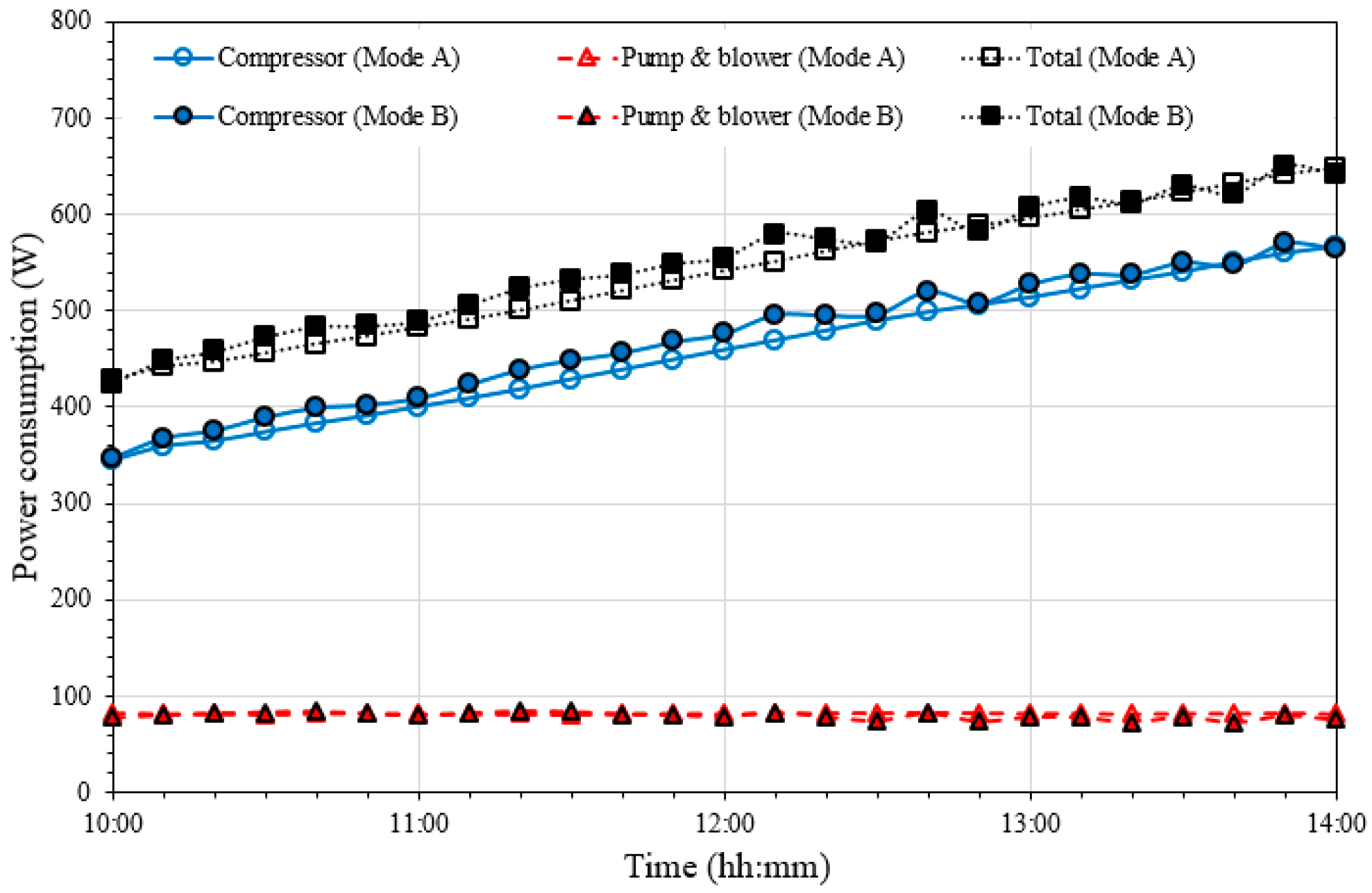
3.3.2. Power Consumption

Figure 12 shows the power consumption of the compressor, pump, and blower. The average power consumption of the compressor is 458.23 W for Mode A and 470.53 W for Mode B. This is because Mode A has a higher evaporating temperature and lower condensing temperature than Mode B, as Mode A only uses heated air, leading to a reduced compression ratio in the heat pump. After 12:00, Mode B exhibits small fluctuations in power consumption due to changes in the evaporator inlet air temperature. However, the power consumption tends to increase continuously throughout the entire experiment. The difference in power consumption of the pump and blower remains insignificant. The system’s daily average power consumption is 540.55 W for Mode A and 550.25 W for Mode B. Therefore, to evaluate the performance of the proposed system, both the heat gain and power consumption should be considered. Thus, in the next section, the COP of the heat pump and system is discussed.

3.3.3. Coefficient of Performance

Figure 13 shows the heat gain in the condenser, power consumption of the compressor, and COP of the heat pump. The heat gain and compressor power consumption increase over time. The COP decreases from a maximum of 2.94 to a minimum of 2.02 in Mode A, and from 2.61 to 1.78 in Mode B. These results indicate better heat pump performance in Mode A. However, a comprehensive performance analysis of the proposed system is necessary, considering not only the heat obtained from the DPSC but also the power consumed by the pump and blower.
Figure 14 presents the total heat gain, total power consumption, and COP of the system. Mode B shows a 16.66% higher total heat gain and a 1.89% higher total power consumption compared to Mode A. Additionally, the COP of the proposed system reaches a maximum of 2.40 and an average of 2.02 in Mode A, while Mode B shows a maximum of 3.14 and an average of 2.33. These results confirm that Mode B has a 14.42% higher system COP compared to Mode A.

4. Conclusions

In this study, a novel type of SAHP combined with the DPSC was proposed. The experiments were performed under natural weather conditions. The proposed system was also compared with the traditional SAHP mode that uses only heated air to evaluate the influence of operating modes. The main conclusions are as follows:
(1) The thermal efficiency of the DPSC in Mode A and Mode B is 62.96% and 56.32%, respectively. As the inlet water temperature increases, heat loss increases, resulting in a decrease in thermal performance in Mode B.
(2) The daily average rate of heat gain in the condenser was 1078.13 W for Mode A and 1253.38 W for Mode B. In Mode B, the average heat gain for the DPSC and the condenser was 306.75 W and 946.62 W, respectively, resulting in a heating performance that was approximately 16.66% higher compared to Mode A.
(3) The power consumption of the compressor is 458.23 W in Mode A and 470.53 W in Mode B. Additionally, the daily average power consumption of the proposed system, including the pump and blower, is 540.55 W for Mode A and 550.25 W for Mode B, representing an increase of about 1.8% in Mode B.
(4) The daily average COPHP is 2.39 in Mode A and 2.04 in Mode B, showing higher performance in Mode A. However, the daily average COPsys is 2.02 and 2.33 in Mode A and Mode B, respectively. Therefore, it was confirmed that using both air and water simultaneously (Mode B) increases performance by 14.42% compared to using only air (Mode A).
From the obtained results, it was clearly confirmed that the performance of the proposed SAHP is better than the traditional SAHP mode. Therefore, the results of this study are meaningful as basic data related to SAHP combined with DPSC.
However, this study was conducted under similar weather conditions instead of identical conditions. Hence, in future research, we plan to perform mathematical modeling of the proposed system and evaluate its performance under various conditions, including different weather conditions and operating methods to reveal the performance improvement of the system more accurately.

Author Contributions

Conceptualization, K.-A.M. and K.-H.C.; Methodology, K.-A.M., S.-B.K. and H.-U.C.; Formal analysis, H.-U.C.; Investigation, S.-B.K. and K.-H.C.; Data curation, S.-B.K.; Writing—original draft, K.-A.M.; Writing—review & editing, H.-U.C. and K.-H.C. All authors have read and agreed to the published version of the manuscript.

Funding

This research was funded by the Ministry of Education and the National Research Foundation of Korea (NRF) through the Leaders in Industry-university Cooperation 3.0 (LINC 3.0) program.

Data Availability Statement

Data are contained within the article.

Conflicts of Interest

The authors declare no conflict of interest.

Nomenclature

Symbols
AArea (m2)
COPCoefficient of performance (-)
C P Specific heat (J/kg°C)
G Solar irradiation (W/m2)
m ˙ Mass flowrate (kg/s)
QHeat transfer rate (W)
TTemperature (°C)
WPower consumption (W)
Greek symbols
ηThermal efficiency (-)
Subscripts
aAir
cCollector
condCondenser
compCompressor
DPSCDual-purpose solar collector
HPHeat pump
sysSystem
wWater

References

  1. Yoon, S.; Kim, M.; Seo, J.; Kim, S.; Lee, H.; Lee, J.; Lee, B.J. Performance Analysis of a Hybrid HVAC System Consisting of a Solar Thermal Collector and a Radiative Cooling Panel. Energy Build. 2021, 241, 110921. [Google Scholar] [CrossRef]
  2. Assari, M.R.; Basirat Tabrizi, H.; Jafari, I. Experimental and Theoretical Investigation of Dual Purpose Solar Collector. Sol. Energy 2011, 85, 601–608. [Google Scholar] [CrossRef]
  3. Mohajer, A.; Nematollahi, O.; Joybari, M.M.; Hashemi, S.A.; Assari, M.R. Experimental Investigation of a Hybrid Solar Drier and Water Heater System. Energy Convers. Manag. 2013, 76, 935–944. [Google Scholar] [CrossRef]
  4. Nematollahi, O.; Alamdari, P.; Assari, M.R. Experimental Investigation of a Dual Purpose Solar Heating System. Energy Convers. Manag. 2014, 78, 359–366. [Google Scholar] [CrossRef]
  5. Zhang, D.; Li, J.; Gao, Z.; Wang, L.; Nan, J. Thermal Performance Investigation of Modified Flat Plate Solar Collector with Dual-Function. Appl. Therm. Eng. 2016, 108, 1126–1135. [Google Scholar] [CrossRef]
  6. Hu, Z.; Luo, B.; He, W.; Hu, D.; Ji, J.; Ma, J. Performance Study of a Dual-Function Roof Solar Collector for Chinese Traditional Buildings Application. Appl. Therm. Eng. 2018, 128, 179–188. [Google Scholar] [CrossRef]
  7. Hao, W.; Lu, Y.; Lai, Y.; Yu, H.; Lyu, M. Research on Operation Strategy and Performance Prediction of Flat Plate Solar Collector with Dual-Function for Drying Agricultural Products. Renew. Energy 2018, 127, 685–696. [Google Scholar] [CrossRef]
  8. Ma, J.; Zhao, Q.; Su, Y.; Ji, J.; He, W.; Hu, Z.; Fang, T.; Wang, H. The Thermal Behavior of a Dual-Function Solar Collector Integrated with Building: An Experimental and Numerical Study on the Air Heating Mode. Energies 2018, 11, 2402. [Google Scholar] [CrossRef]
  9. Pathak, P.K.; Chandra, P.; Raj, G. Comparative Analysis of Single- and Dual-Purpose Corrugated Plate Solar Collector by Force Convection. Heat Transf.-Asian Res. 2019, 48, 2387–2401. [Google Scholar] [CrossRef]
  10. Pathak, P.K.; Chandra, P.; Raj, G. Comparative Analysis of Modified and Convectional Dual Purpose Solar Collector: Energy and Exergy Analysis. Energy Sources Part A Recover. Util. Environ. Eff. 2019, 1–17. [Google Scholar] [CrossRef]
  11. Shemelin, V.; Matuska, T. Performance Modelling of Dual Air/Water Collector in Solar Water and Space Heating Application. Int. J. Photoenergy 2019, 2019, 8560193. [Google Scholar] [CrossRef]
  12. Somwanshi, A.; Sarkar, N. Thermal Performance of a Dual-Purpose Collector-Cum-Storage Type Air-Water Heater. Appl. Therm. Eng. 2020, 171, 115094. [Google Scholar] [CrossRef]
  13. Hasan, M.M.; Hriczó, K. A Literature Review of a Dual-Purpose Solar Collector. Veh. Automot. Eng. 2022, 3, 302–321. [Google Scholar]
  14. Çomakli, Ŏ.; Kaygusuz, K.; Ayhan, T.; Arslan, F. Experimental Investigation and a Dynaminc Simulation of the Solar-Assisted Energy-Storaged Heat Pump System. Sol. Energy 1993, 51, 147–158. [Google Scholar] [CrossRef]
  15. Li, Y.W.; Wang, R.Z.; Wu, J.Y.; Xu, Y.X. Experimental Performance Analysis and Optimization of a Direct Expansion Solar-Assisted Heat Pump Water Heater. Energy 2007, 32, 1361–1374. [Google Scholar] [CrossRef]
  16. Dikici, A.; Akbulut, A. Performance Characteristics and Energy-Exergy Analysis of Solar-Assisted Heat Pump System. Build. Environ. 2008, 43, 1961–1972. [Google Scholar] [CrossRef]
  17. Wang, Q.; Liu, Y.Q.; Liang, G.F.; Li, J.R.; Sun, S.F.; Chen, G.M. Development and Experimental Validation of a Novel Indirect-Expansion Solar-Assisted Multifunctional Heat Pump. Energy Build. 2011, 43, 300–304. [Google Scholar] [CrossRef]
  18. Fernández-Seara, J.; Piñeiro, C.; Alberto Dopazo, J.; Fernandes, F.; Sousa, P.X.B. Experimental Analysis of a Direct Expansion Solar Assisted Heat Pump with Integral Storage Tank for Domestic Water Heating under Zero Solar Radiation Conditions. Energy Convers. Manag. 2012, 59, 1–8. [Google Scholar] [CrossRef]
  19. Liu, Y.; Ma, J.; Zhou, G.; Zhang, C.; Wan, W. Performance of a Solar Air Composite Heat Source Heat Pump System. Renew. Energy 2016, 87, 1053–1058. [Google Scholar] [CrossRef]
  20. Hematian, A.; Ajabshirchi, Y.; Ranjbar, S.F.; Taki, M. An Experimental Analysis of a Solar-Assisted Heat Pump (SAHP) System for Heating a Semisolar Greenhouse. Energy Sources Part A Recover. Util. Environ. Eff. 2019, 43, 1724–1744. [Google Scholar] [CrossRef]
  21. Singh, A.; Sarkar, J.; Sahoo, R.R. Experimental Energy, Exergy, Economic and Exergoeconomic Analyses of Batch-Type Solar-Assisted Heat Pump Dryer. Renew. Energy 2020, 156, 1107–1116. [Google Scholar] [CrossRef]
  22. Sharaborova, E.S.; Shepitko, T.V.; Loktionov, E.Y. Experimental Proof of a Solar-Powered Heat Pump System for Soil Thermal Stabilization. Energies 2022, 15, 2118. [Google Scholar] [CrossRef]
  23. Choi, H.U.; Kim, Y.B.; Son, C.H.; Yoon, J.I.; Choi, K.H. Experimental Study on the Performance of Heat Pump Water Heating System Coupled with Air Type PV/T Collector. Appl. Therm. Eng. 2020, 178, 115427. [Google Scholar] [CrossRef]
  24. Choi, H.U.; Choi, K.H. Numerical Study on the Performance of a Solar-Assisted Heat Pump Coupled with a Photovoltaic-Thermal Air Heater. Energy 2023, 285, 129480. [Google Scholar] [CrossRef]
  25. Wu, J.; Shen, M.; Feng, J. The Application of a Solar–Air-Source Heat Pump Dual-Supply Heating System in a High-Cold Area in China. Processes 2023, 11, 737. [Google Scholar] [CrossRef]
  26. Vengadesan, E.; Bharathwaj, D.; Kumar, B.S.; Senthil, R. Experimental Study on Heat Storage Integrated Flat Plate Solar Collector for Combined Water and Air Heating in Buildings. Appl. Therm. Eng. 2022, 216, 119105. [Google Scholar] [CrossRef]
Figure 1. Schematic view of the DPSC.
Energies 17 03038 g001
Figure 2. Schematic diagram of the proposed SAHP system.
Energies 17 03038 g002
Figure 3. Comparative operating mode of the proposed SAHP.
Energies 17 03038 g003
Figure 4. Variation in solar irradiation and ambient temperature.
Energies 17 03038 g004
Figure 5. Variation in working fluid temperature at DPSC.
Energies 17 03038 g005
Figure 6. Variation in heat gain at DPSC.
Energies 17 03038 g006
Figure 7. Variation in thermal efficiency at DPSC.
Energies 17 03038 g007
Figure 8. Variation in temperature and heat gain of a heat pump.
Energies 17 03038 g008
Figure 9. Variation in total heat gain of the proposed system.
Energies 17 03038 g009
Figure 10. Variation in thermal storage tank temperature.
Energies 17 03038 g010
Figure 11. Heat gain per hour from SAHP and thermal storage tank.
Energies 17 03038 g011
Figure 12. Variation in the power consumption.
Energies 17 03038 g012
Figure 13. Comparison of performance based on operation mode.
Energies 17 03038 g013
Figure 14. Comparison of the SAHP system based on operation mode.
Energies 17 03038 g014
Table 1. The dimensions of the DPSC.
ParameterSpecification
Size of the DPSC (L × W × H)1980 mm × 982 mm × 100 mm
Area of an absorber plate1.91 m2
Distance between glass and absorber plate20 mm
Absorber plate thickness0.7 mm (copper plate)
Outer diameter of water pipe12.7 mm
Inner diameter of water pipe10 mm
Number of pipes9 ea
Height of the airflow path70 mm
Width of each airflow path960 mm
Fin height70 mm
Fin thickness2 mm
Table 2. Specification of the heat pump components.
ItemSpecificationValue
CompressorModel name39A172A
Input power695 W
CondenserTypePlate heat exchanger
Number of the plate20 ea
Size (W × H × L)77 mm × 207 mm × 55 mm
EvaporatorTypeFin-tube heat exchanger
Size (W × H × L)230 mm × 210 mm × 20 mm
Table 3. Experimental conditions.
Operating ModeMode AMode B
Date (Day/Month/Year)10/02/202411/02/2024
Time (hh:mm)10:00~14:00
Air mass flowrate (kg/s)0.06350.0609
water flow rate (kg/s)0.050.05
Initial thermal storage tank temperature (°C)10.4213.89
Hot water tank capacity (L)150
Table 4. Specification on measurement instruments.
InstrumentModelRangeAccuracyUncertainty
PyranometerMS-802
(EKO instrument, MS-802, Tokyo, Japan)
0~4000 W/m2±10 W/m2±2%
ThermocoupleT-type−270~370 °C±1 °C±0.75%
AnemometerKanomax 6531-2G
(Kanomax Japan Inc., 6531-2G, Suita, Japan)
0.01~30 m/s±0.6 m/s±2%
Turbine flow sensorGMP
(Nuritech, GMP, Siheung, Republic of Korea)
3.8~38 L/min±0.4 L/min±1%
PowermeterPW3336
(Hioki, PW3336, Nagano, Japan)
3 W~100 kW±0.05 W ±0.1%
Data loggerAgilent 34972A
(keysight, 34972A, Santa Rosa, CA, USA)
---
Disclaimer/Publisher’s Note: The statements, opinions and data contained in all publications are solely those of the individual author(s) and contributor(s) and not of MDPI and/or the editor(s). MDPI and/or the editor(s) disclaim responsibility for any injury to people or property resulting from any ideas, methods, instructions or products referred to in the content.

