Article

Study on the Influences of an Outer-Coreless-Rotor Permanent Magnet Synchronous Machine Using Halbach Magnet Array

1
School of Electrical Engineering and Automation, Harbin Institute of Technology, Harbin 150001, China
2
Science and Technology on Reactor System Design Technology Laboratory, Nuclear Power Institute of China, Chengdu 610213, China
*
Author to whom correspondence should be addressed.
Energies 2024, 17(13), 3108; https://doi.org/10.3390/en17133108
Submission received: 20 May 2024 / Revised: 17 June 2024 / Accepted: 20 June 2024 / Published: 24 June 2024
(This article belongs to the Special Issue Linear/Planar Motors and Other Special Motors)

Abstract

:
In order to evaluate the influences of the topology design of a Halbach Magnet Array (HA) on the performance of a motor, a PMSM with an outer coreless rotor using a Halbach Magnet Array (HAORPMSM) is proposed in this article. The design parameters of the HA could be separated into dividing methods per pole, magnet thickness, and initial magnetization direction angle. The phase Back-EMF under constant mechanical speed is chosen as the index to measure the performance of the motor. To start with, different dividing methods of the HA are evaluated. After that, the influence of thickness considering the utilization of the magnet is studied. Lastly, the relationship between initial magnetization direction and motor manufacturing is represented. The results show that the HA design meets the optimized performance considering the balance of the amount of magnet usage and manufacturing when using specific HA parameters.

1. Introduction

Permanent Magnet Synchronous Machines (PMSMs) have been developed rapidly within the past few decades. PMSMs can reach higher torque densities due to the development of Permanent Magnet Materials for high-energy products including remanence and coercivity [1,2]. In recent years, PMSMs using Permanent Magnets (PMs) as the source of magnetic field excitation are directly widely used within many applications including Electric Vehicles [3,4,5], electric helicopters and air-crafts [6,7,8], and marine drivings [9,10,11]. According to the position of the rotor compared with the stator, the PMSM can be separated into an Outer-Rotor PMSM (ORPMSM) and Inner-Rotor PMSM (IRPMSM). Also, rotors without the use of an iron core is another design topology.
The Halbach Magnet Array (HA) [12] has been used in a wide variety of applications for its concentrated magnetic field on a specified face of a magnet [13]. Motors using the HA have been used in a wide range of electric vehicle drives [14], spacecraft [15], or rail-guns [16]. The HA is also used in wireless power transfer [17] as a magnetic resonator, which leads to 50 times more power delivered without increasing magnetic field exposure. The magnetic gear [18] is another important application using the HA, and the torque density of the coaxial magnetic gear using the HA could be up to 173 kNm/m3. The electromagnetic pump using the HA could meet the performance of minimum inlet pressures of 0.1 bar [19]. Besides motors, the HA is used in many applications including flowmeters and medical equipment. A flowmeter using the HA and designed for liquid metal flow measurement could improve the sensitivity by 68% [20]. Desktop nuclear magnetic resonance systems (NMR) and magnetic resonance imaging systems (MRI) are examples of medical applications using the HA [21].
Currently, major researchers are focusing on the dividing method of the HA. A common design path is to change the proportion of horizontal blocks and vertical blocks within a single pole [22,23]. Some researchers are considering dividing every single pole into several blocks with different widths [18,24,25] or combining blocks with different magnetization directions [26].
In [27], an axial air-gap magnetic field model of an HA Permanent-Magnet Spherical Motor is built. In order to optimize the air-gap flux density, fundamental harmonic amplitude, and waveform distortion rate, the axial air-gap magnetic field considering the end leakage of the HA is analysed. In [28], a PMSM using an HA is studied. A single pole of an HA is separated into five blocks and several parameters including the thickness, width, and magnetization direction of every block. The results show that these structural parameters have a great impact on the performance of the motor. In [29], a PM machine using an HA for high-speed dynamo application is introduced. Compared with previous works, the thickness of the rotor yoke is mainly focused on and optimized. Meanwhile, a single pole of an HA is separated into two blocks with different widths, and the ratio of widths is studied in this article. In order to improve the output torque, Yang et al. [30] proposed a flux reversal permanent machine with a reduction in the leakage flux. The HA is used in the machine to reduce the leakage flux. With the support of a tangential magnet, reversal fluxes which go back to the opposite magnet are prevented and the output torque is improved.
One of the major advantages of using a PMSM is its high torque and power density. For some applications which have demands of both significant power and strict volume limitations such as robot knee joints, an iron core may not be used in the rotor, due to manufacturing. Under such conditions, a coreless outer rotor machine could be a superb technical path. Besides that, the HA might be a good way to improve the air gap flux density for its concentrating phenomenon. In order to evaluate the influences of the parameters of the HA on the performance of the otor, a coreless-outer-rotor Permanent Magnet Synchronous Machine using a Halbach Magnet Array (HAORPMSM) is studied in this article. The machine is designed under the combination of 10 poles and 12 slots. Furthermore, some parameters of the HA including the thickness of the magnet, the initial magnetization direction angle, and the pole dividing block number are studied in detail. The shape of all blocks of the HA are considered the same. A simulation method is used for evaluation. The software used is Ansys EM suite 2021 R2, and the module is Maxwell 2D.

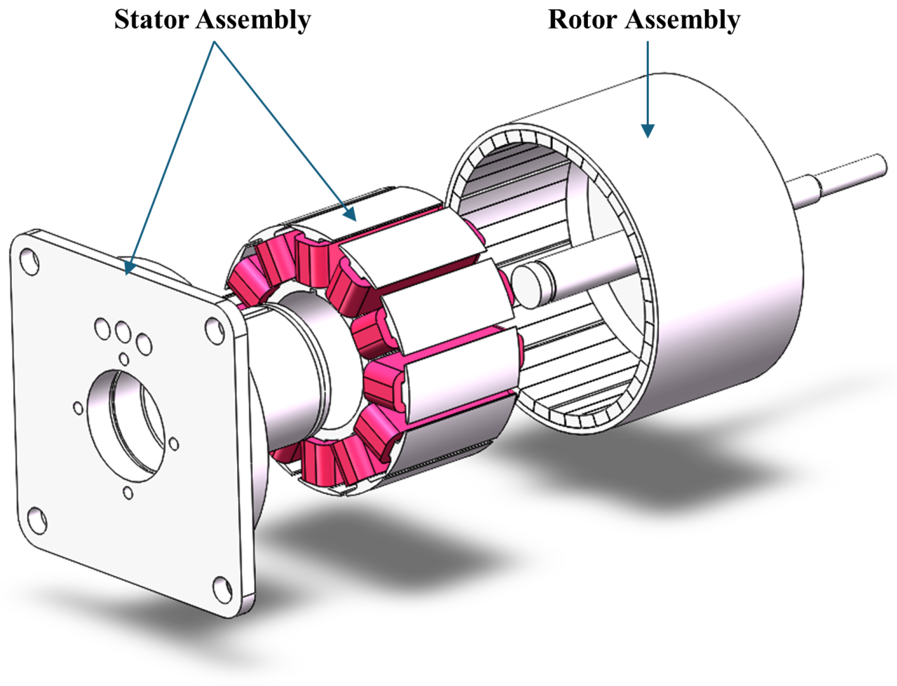
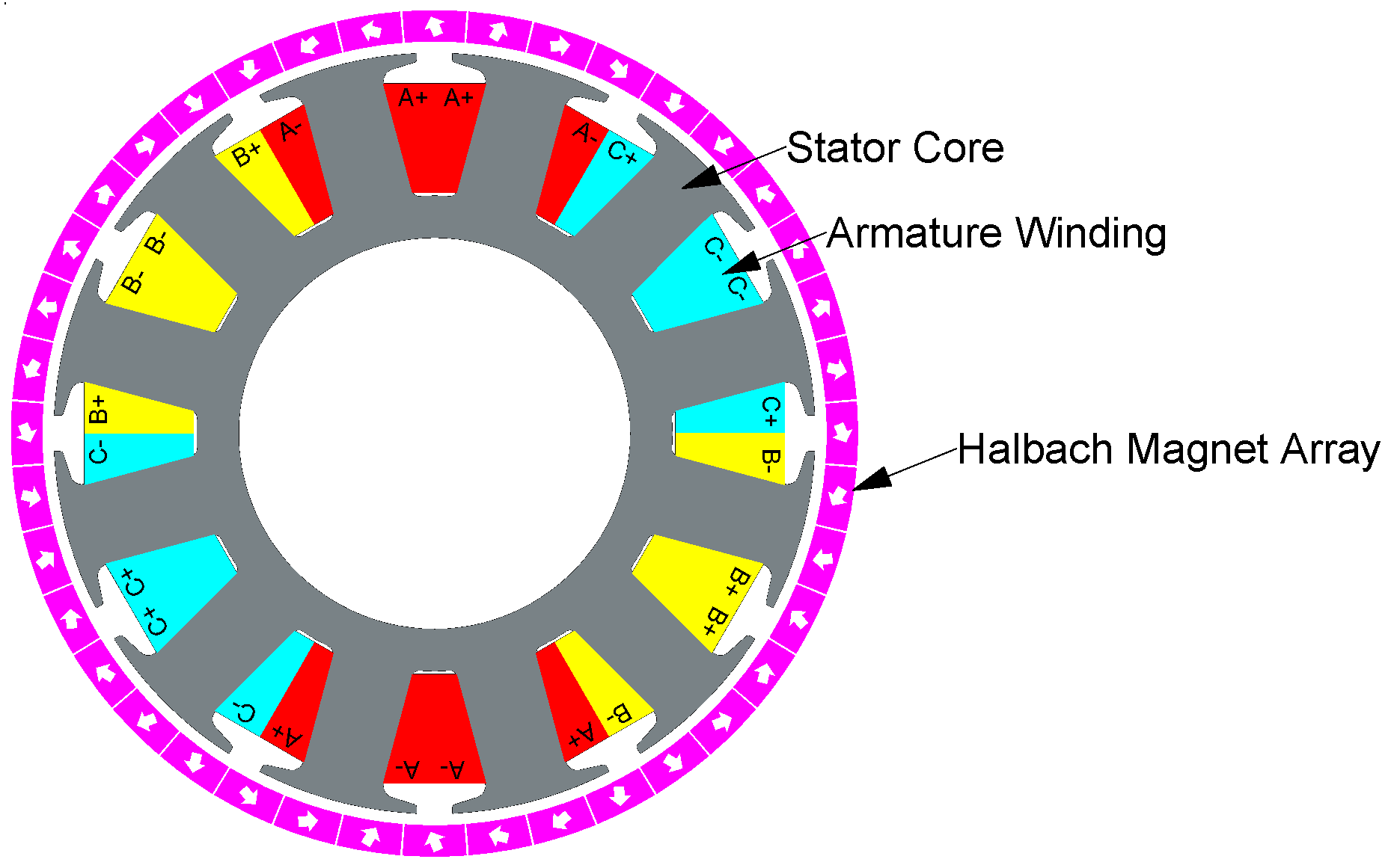
2. Topology and Analytical Model

The basic design parameters of the motor are given in Table 1, and the machine is displayed in Figure 1.
A single pole is divided into 4 blocks without blanks. The motor is a 10-pole motor and the rotor HA is formed by 40 blocks of PMs. All PMs combine to form a ring of magnets. The magnet ring is glued to a aluminum-alloy-made rotor housing. The shaft is screwed to the rotor housing of the motor. The rotor assembly is assembled by a rotor HA, rotor housing, and shaft. No iron core is used in the rotor assembly; hence, it is a coreless rotor. The stator iron core is made of silicon steel sheets. The material of the armature winding is an enameled round copper wire. The stator iron core is attached to an aluminum-alloy-made stator stander through a key. The stator assembly is assembled by a stator iron core, armature winding, and stator stander. The stator assembly and rotor assembly are connected through 2 bearings at the front and rear of the motor.
Due to the combination of 10 poles and 12 slots, the armature has a concentrated winding; hence, the coil pitch is 1.
The cross-sectional view of the HAORPMSM is shown in Figure 2. The gray part in the figure is stator iron core. Parts in yellow, red and blue are armature windings of stator. Purple parts are PM blocks combining as Halbach Magnet Array, where the white arrows are showing the magnetization direction in every single PM block.
Detailed angles of the dividing method are shown in Figure 3 where the arrows are also the magnetization directions to every single PM block. θ b l o c k is the angle of a single block. θ Δ is the magnetization direction angle rotated in every block step in the array. H m a g is the thickness of the magnet. And θ i n i is the initial angle between the magnetization direction of the block which is facing the original direction of the pole and the direction of the pole. The angles in Figure 3 can be calculated using
θ b l o c k = 360 ° k · 2 p
θ Δ = 180 ° k
where k is the number of blocks combined as one pole in the HA.
In order to evaluate the influence of H m a g on the performance of a motor, the Finite Element Analysis (FEA) method was used. The simulating software used in this article was Ansys Electronics and the module was Maxwell 2D. The simulation FEA model is shown in Figure 4. It shows that the width of a tooth is over-designed in order to ensure no saturation in the stator tooth. Meanwhile, Figure 4 shows one pole divided into 4 blocks i.e., k = 4 .

3. Influences of Halbach Array Parameters on Open-Circuit Phase Back-EMF

The topology of the simulation of the electromagnetic field involves keeping the parameters in Table 1 constant and changing the parameters of the HA, including k, H m a g , and θ i n i , to observe the variety in motor performance. The open-circuit back Electro-Motive Force (EMF) is a physical quantity representing the ability to generate voltage under certain rotating speeds. It approximately refers to following equations:
Ψ p h = N · ϕ a v g
E p h = d Ψ p h d t
K E = E p h n
K T = T e m m · I p h = 0.00955   K E
where Ψ p h is the phase flux-linkage. N is total number of turns per coil in one phase. ϕ a v g is the average flux of every coil connected in phase. E p h is the root-mean-square value (RMS) of the phase-induced voltage or Back-EMF. K E is the Back-EMF constant in units of V/krpm that represents the ability to generate voltage. n is the mechanical rotating speed in krpm. K T is the torque constant that represents the ability to output motor torque. T e m is the electromagnetic torque output. m is the phase number. I p h is the phase current in the RMS. In fact, K E and K T share a linear relationship with Ψ p h . As a result, E p h under certain speeds could be considered as approximately the measurement value of the motor performance. In this article, the mechanical rotating speed is considered as 1500 rpm and its mechanical duty cycle is 40 ms for benefits in calculating the accuracy in high-ordered harmonics.

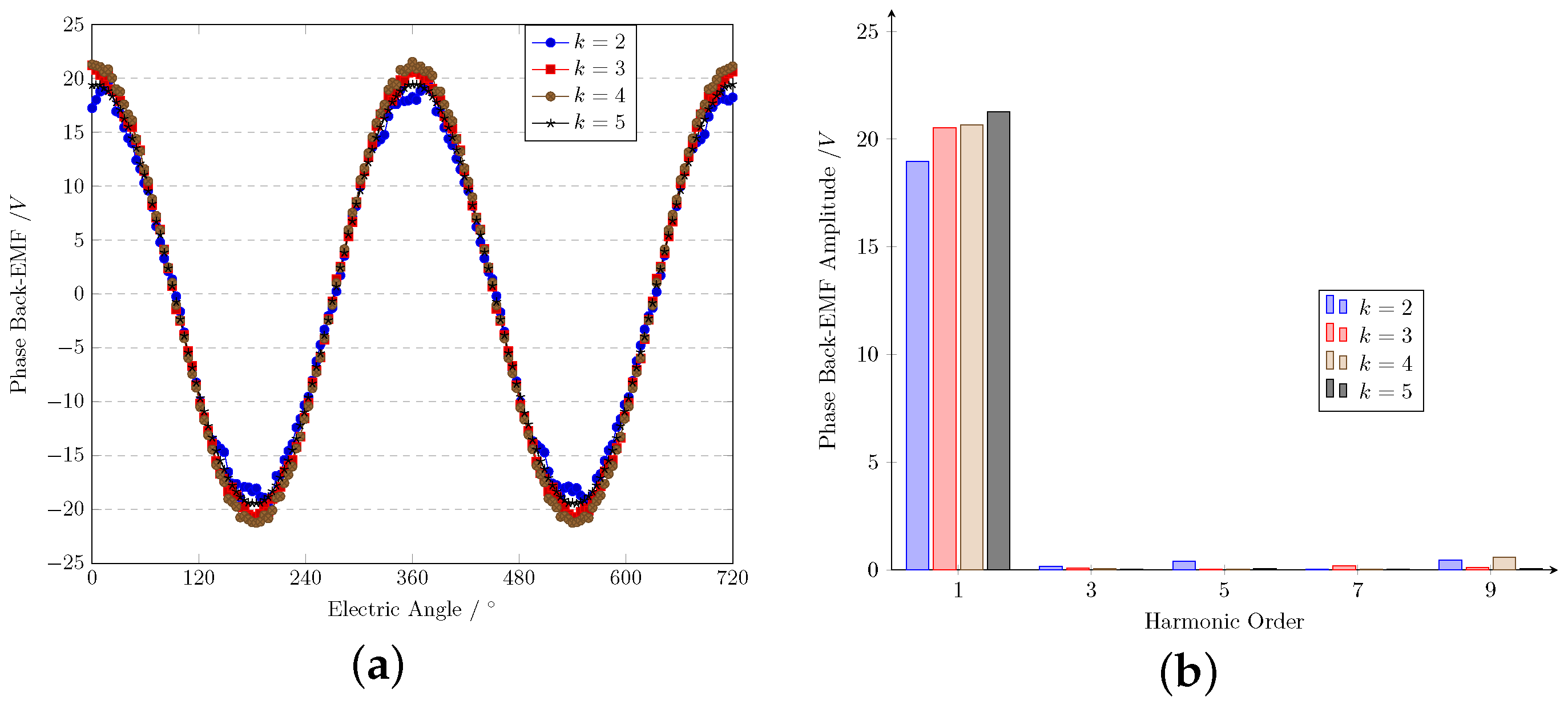
3.1. Influence of Dividing Number per Pole

The dividing number of PMs per pole within the HA is k. This value has a significant influence on motor performance in the scale of K E and K T for the HAORPMSM. In order to quantify the influence of k, other parameters have to remain constant. In this section, besides the parameters shown in Table 1, H m a g is set to 2.5 mm and θ i n i is zero. k is increased from 2 to 5 in steps of 1.
The simulation result of the phase Back-EMF is shown in Figure 5a, and the frequency domain analysis using a Fourier Transform of its fundamental, 3rd, and 5th harmonics is shown in Figure 5b. Values within Figure 5b are arranged in Table 2. Table 2 also indicates the Total Harmonic Distortion (THD). The values are shown in the phase Back-EMF when the mechanical speed of the rotor is 1500 rpm.
The results show that the phase Back-EMF has an excellent sinusoidal waveform and few high-ordered harmonics.
It can be observed that the phase Back-EMF is improved with the increase in k under all the conditions. The frequency domain indicates that the fundamental amplitude of the phase Back-EMF increased by 10.4% from 18.59 V to 20.53 V when k = 3 compared with k = 2 . At the same time, the third harmonic of the phase Back-EMF decreased from 170.9 mV to 74.87 mV. It should be mentioned that the value of the third-harmonic amplitude meets a minimum value when k = 3 , which leads to the extraordinary performance of THD. The improvement in high-ordered harmonics is the fact that leads to the enhancement in phase Back-EMF. The phase Back-EMF also increased 0.7% when k rose from 3 to 4 and 2.9% from 4 to 5. The fundamental amplitude of the phase Back-EMF almost remained stable when k increased after reaching 5. The 3rd and 5th harmonic amplitude decreased tremendously when k rose from 2, which is the main fact leading to the improvement in fundamental amplitude. Also, it is the 7th and 9th harmonics that lead to the fundamental rise when k reaches 4 and 5. In general, THD decreased, and the fundamental amplitude improved along with the increase in k.
This phenomenon shows that k and motor performance can be recognized as a positive correlation. Motor performances enhance along with the increase in k. The phase Back-EMF rises tremendously when k increases from 2 to 3 and this trend weakens when k is larger under constant mechanical speed. The performances of the motor change little when k > 5 . Also, the difficulty in manufacturing and the cost will increase if k is larger. As a result, the recommended value of k is 4.

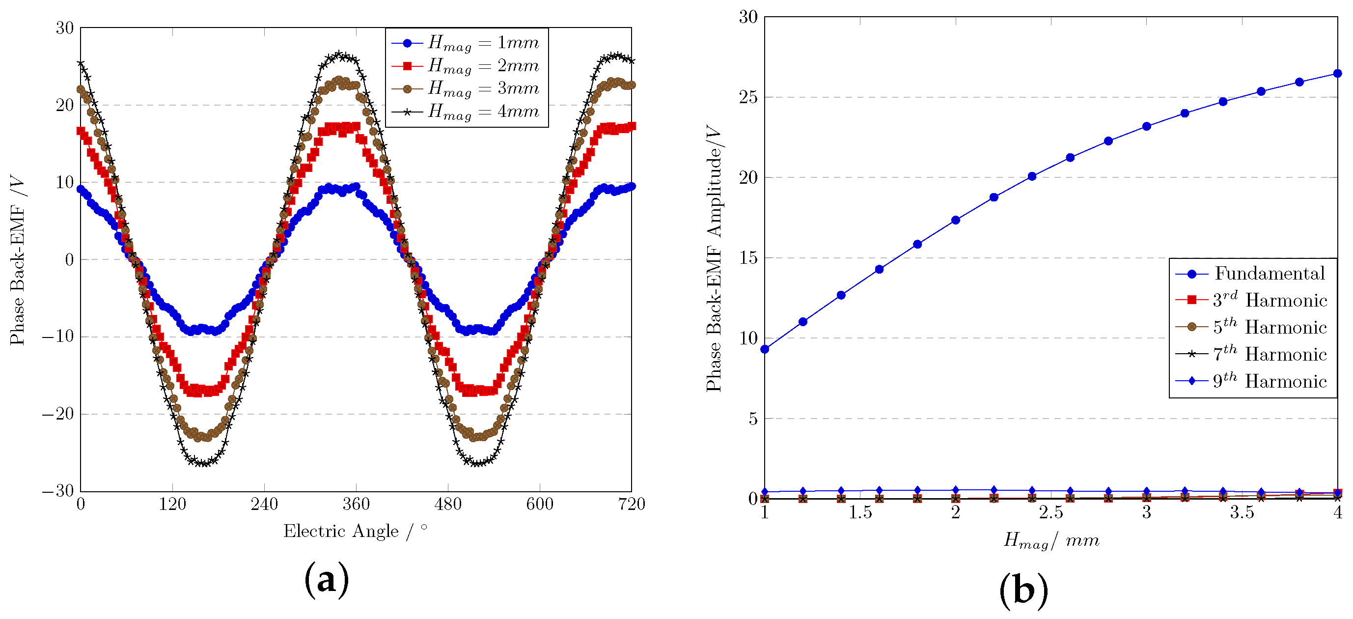
3.2. Influence of Magnet Thickness

In this article, the thickness of the magnet is H m a g , which will surely influence the performance of the HAORPMSM as it represents the amount of magnet used in the motor. In this section, H m a g is increased and the phase Back-EMF is observed under a certain mechanical speed. The parameters in Table 1 remain constant, k is set as 4, and θ i n i is zero. H m a g linearly increases in steps of 0.2 mm.
The simulation result of the phase Back-EMF when k = 4 is shown in Figure 6a, and the frequency domain analysis using the Fourier Transform of its fundamental amplitude is shown in Figure 6b. Some feature values of H m a g within Figure 6b are arranged in Table 3. The THD is also indicated in Table 3. The mechanical rotating speed of the motor rotor is 1500 rpm.
It can be observed that the phase Back-EMF increases along with the increase in H m a g , which agrees with the theory. At the same time, the third harmonic rises rapidly, which does not agree with the increase in fundamental amplitude. The data illustrate that the high-ordered harmonics have their own increasing trend. THD could be considered the index to measure high-ordered harmonic circumstances, whilst the THD meets a minimum value when H m a g = 2.5 mm, which is 2.3%.
In practice, the value of H m a g with a minimum THD is influenced by several factors including the length of the air-gap, stator slot width, etc. In general, it occurs when H m a g is almost equal to half of the arc length per block.
In order to analyze the utilization of the magnet, a factor k M U is defined in this article as
k M U = Δ V Δ m P M = Δ V ρ · L · Δ S = Δ V ρ · L · π · Δ r 2 k M U Δ V Δ r 2
where Δ V is the variation in phase Back-EMF when H m a g changes. Δ m P M is that of a permanent-magnet mass. ρ is the density of the PM. L is the axial length of the motor. Δ S is the variation in cross-sectional area. And Δ r is the variation in the thickness of the magnet. This factor represents the changing rate of the Phase Back-EMF per mass unit of the PM. As a result, this factor can be recognized as the relationship between the phase Back-EMF variation and the changing radian squared when the axial length remains constant.
Figure 7 shows the relationship between k M U and H m a g when k = 4 , where H m a g and k M U share an inverse functional relationship. k M U decreases tremendously when H m a g increases from 1.0 mm to 2.0 mm, and this decrease trend lessens after H m a g reaches 3.0 mm. The curve of k M U meets an inflection point between 2.0 mm and 3.0 mm, which means that the optimized H m a g value considering the utilization of the magnet mass and motor performance should be within this range.
In general, considering both k M U and THD, the optimized thickness of the HA is 2.5 mm, which agrees with the following functions:
l b l o c k = θ b l o c k · r
H m a g 1 2 · l b l o c k
Function (9) shows that the utilization of the magnet k M U and the high-ordered harmonic THD are optimized when the thickness of the permanent magnet in the Halbach Array H m a g equals half of the arc length per block l b l o c k in the array.

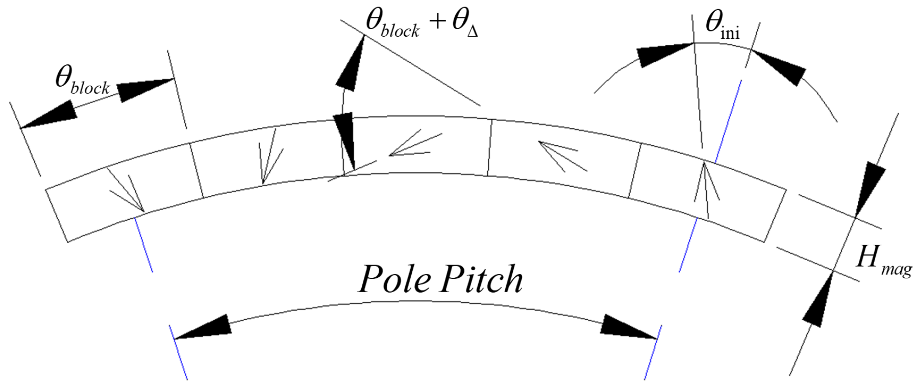
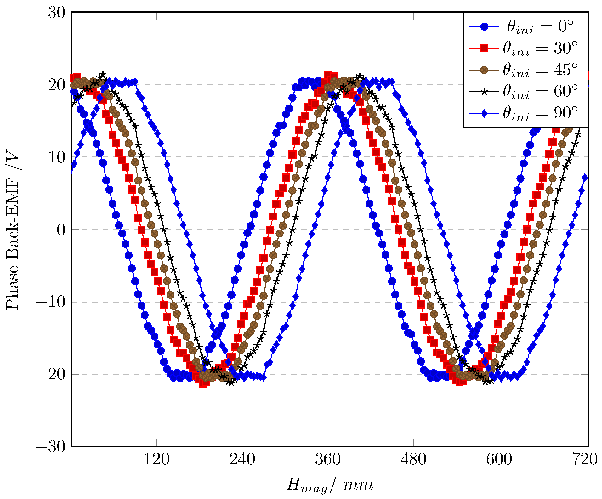
3.3. Influence of Initial Angle and Manufacturing

The initial angle of the HA is θ i n i in this article. This value has little influence on the motor performance but a significant influence on the manufacturing of the motor. The cost and advantage of using the specific θ i n i are indicated in this section.
The design topology of the HA has been clarified in Section 3.1 and Section 3.2. Hence, the design of k = 4 and H m a g = 2.5 mm is used in this section. Besides that, the other main parameters remain constant as in Table 1. θ i n i is increased from 0° to 90° in steps of 15°. The simulation result of the phase Back-EMF against θ i n i is shown in Figure 8, and the frequency domain analysis using the Fourier Transform is shown in Table 4.
These results show that there is little influence on the fundamental amplitudes when θ i n i changes. The amplitude of high-ordered harmonics changes slightly while the THD remains constant. Only the phases of the Back-EMF will be influenced when θ i n i increases from 0° to 90°. It can be recognized that θ i n i has little influence on the performance of the HAORPMSM.
Though θ i n i has little influence on the performance of the HAORPMSM, it is related to the manufacturing of the motor, considering that the HA is made up of PM blocks, and the materials of the permanent magnet are mainly anisotropic [31]. All the blocks of the HA are cut from the original material of the magnet. The original material has its own preset magnetization direction; hence, the shape and magnetization direction of the single PM block has to be designed. The PM blocks divided from a single pole when θ i n i = 0 ° are shown in Figure 9a. A single pole is combined from 3 blocks and 2 half blocks. The blocks indicated by an blue arrow marked ’same’ are actually the same if they are rotated in the radial direction. And blocks indicated by the red arrow marked as ’different’ are different. Hence these different blocks have to be cut from different ways. As a result, a single pole of an HA is combined by four different types of PM blocks when θ i n i = 0 ° . Meanwhile, the situation of θ i n i = 22.5 ° is shown in Figure 9b. In this situation, a single pole is combined by four complete blocks. Also, blocks highlighted by blue arrows are the same when a specific PM block is rotated in the radial direction, and so does blocks indicated by the green arrow. Hence, a single pole of an HA is combined by only two types of PM blocks. Besides that, the cutting design of PM materials and their utilization are also more convenient if θ i n i = 22.5 ° .
In this section, the influence of the HA initial angle θ i n i is evaluated. As a result, this value has little effect on the performance of the HAORPMSM. However, an optimized design of θ i n i will improve the manufacturing of the HAORPMSM majorly. In general, under comprehensive consideration of k and θ i n i , only when k is even and θ i n i agrees with the following functions can the manufacturing have an optimized design:
k = 2 n ,   n N *
θ i n i = 1 2 θ Δ = 90 ° k
where n is the minimum number of blocks combining a single block.
Functions (10) and (11) clarify the design topology of the HA when manufacturing is optimized.

4. Machine Performance

The topology of the simulation of the electromagnetic field keeps the parameters in Table 1 constant. k = 4 , H m a g = 2.5 mm, and θ i n i = 22.5 ° are the optimized parameters (refer to Section 3). Though the aim for this section is to validate the alignment of the numerical and simulated design and prototype, the rated power and working point should be fixed. The speed of the motor is set to 1500 rpm, and the rated power is 350 W. An HAORPMSM simulation model is built using the above parameters.

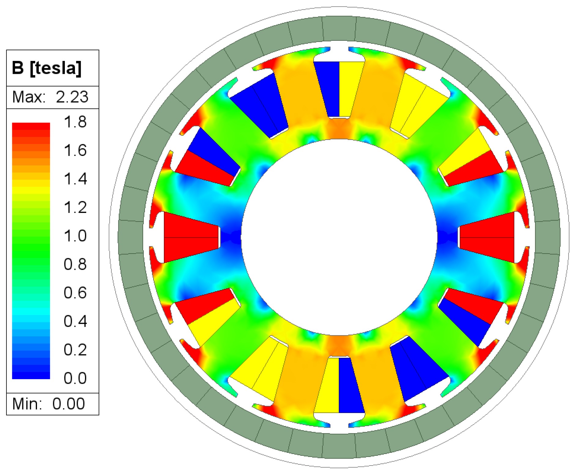
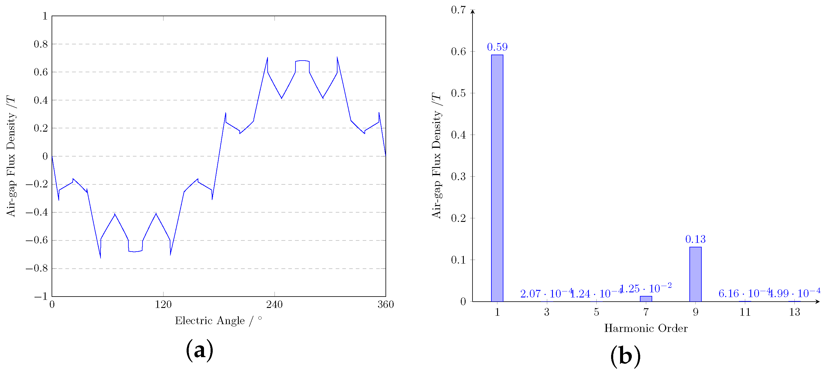
4.1. Open-Circuit Performance

The open-circuit flux density and flux line distributions are shown in Figure 10. The teeth flux densities are clearly not above 1.6 T, and few leakage flux lines enter the shaft and rotor housing.
The open-circuit air-gap flux density waveform and its spectra are shown in Figure 11. The graphs show that the fundamental amplitude of the air-gap flux density is 0.591 T and the ninth harmonic is the highest high-ordered harmonic, which is 131.2 mT. The other ordered harmonics can hardly be observed in Figure 11b. The THD of the open-circuit air-gap flux density is 22.2%.
Figure 12 shows the waveform and spectra of the phase Back-EMF of the HAORPMSM when the mechanical speed is 1500 rpm. The fundamental amplitude of the phase Back-EMF is 20.67 V and the ninth harmonic has the highest amplitude of 0.59 V. The THD of the phase Back-EMF is 2.9%.
K E and K T could be calculated using the following functions:
K E = E p h n = 9.74   V / krpm
K T = 0.00955 · K E = 93.1   mNm / A

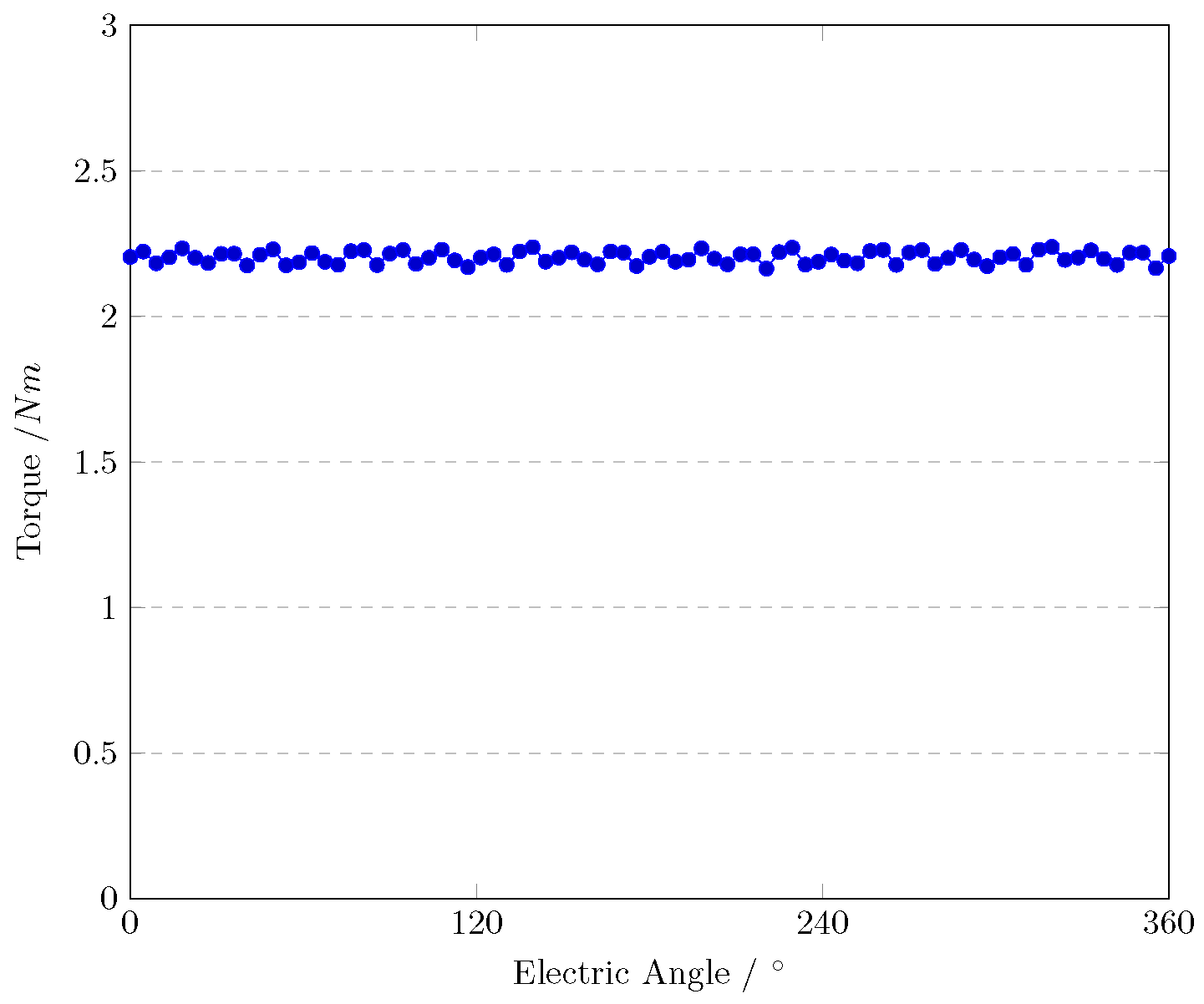
4.2. Torque Performances

Figure 13 shows the waveform of the output torque when I p h = 8 A. The average torque is 2.21 Nm. T p p is the peak-to-peak torque and is 0.075 Nm, covering 3.4% of the average torque. The output torque could be calculated using the following function:
T e m = m · I p h · K T = 2.23   Nm
As a result, the difference between the calculation and simulation is 1.1%, which can be recognized as tolerance.

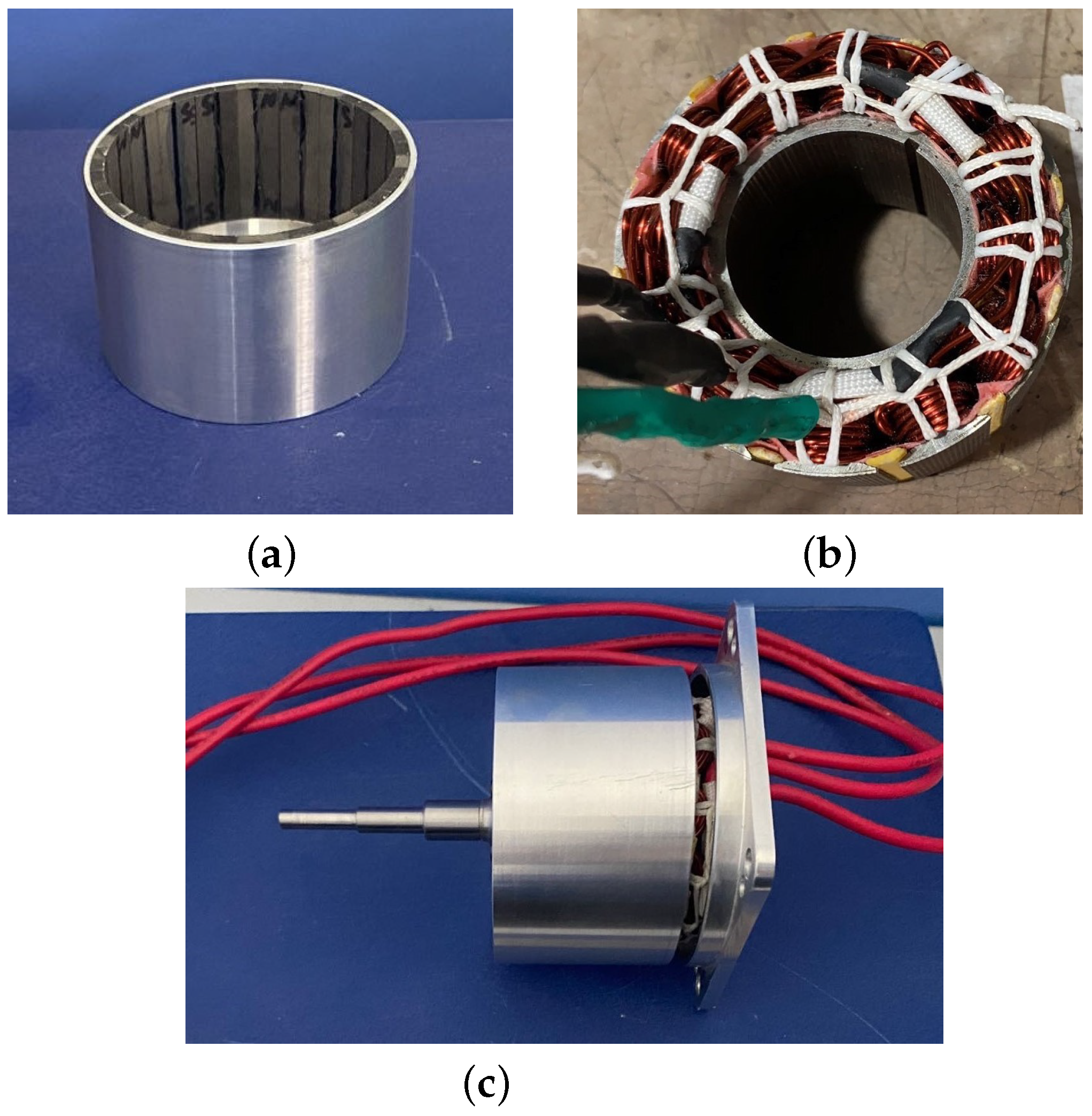
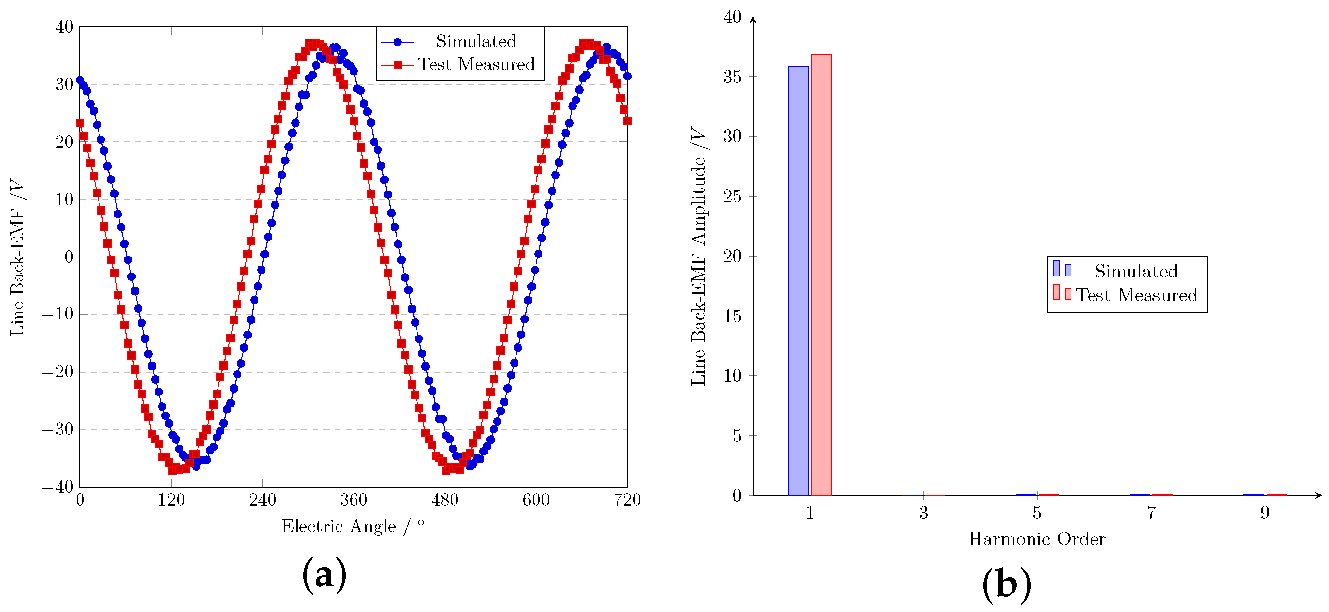
4.3. Experimental Validation

In order to validate the accuracy of the simulation, a small-scale prototype HAORPMSM is designed, manufactured, and tested.
The distributed HAORPMSM has a rotor outer diameter of 72 mm. Pictures of the stator iron core, armature winding, rotor assembly, and general motor are shown in Figure 14. The simulation results obtained by the 2D FEA are compared with the measured waveforms, and the spectra of the line Back-EMF when the speed is 1500 rpm are shown in Figure 15. It should be mentioned that only the open-circuit Back-EMF is measured due to the fact that the on-load Back-EMF cannot be measured. The simulated value of the line Back-EMF fundamental amplitude is 35.80 V and the measured value is 36.85 V. The difference is improved by 2.9%, which is acceptable considering the tolerances of manufacturing and the parameters of the magnet material including remanence and coercivity. As the measured line Back-EMF is quite similar to the simulation results, the K E of the prototype could also be considered the same as the simulation model.
The measured line Back-EMF has an excellent sinusoidal waveform. High-ordered harmonics decreased when the Back-EMF was measured as a line instead of a phase, which led to the vanishing of the 3rd and 9th harmonic. The actual performance is slightly better than that of the simulated model.

5. Conclusions

A novel HAORPMSM is studied in this article. Some design parameters of the HA were analyzed and optimized including the number of dividing blocks per pole k, the thickness of the magnet H m a g , and the initial magnetization direction θ i n i . A prototype of the HAORPMSM was manufactured and measured to validate the design. The following conclusions were obtained.
The dividing method of every single pole of the HA has a significant influence on motor performance. The phase Back-EMF under certain speeds can be improved by 14.7% when k increases from 2 to 5 and no additional PM is used in the motor. The performance improves little when k reaches 5. As a result, considering the balance of manufacturing and motor performance, the design of k meets an optimal solution when k = 4 .
The increase in magnet thickness has an optimized topology. The utilization of a PM is multiple times better when H m a g is tiny compared with when it is very large. In general, the relationship between the utilization of the magnet and H m a g can be approximately recognized as an inverse function. The waveform has an inflection point when H m a g is equal to half of the arc length of every block, which means that at this point, the balance of motor performance and the utilization of the magnet has an optimized design.
The initial magnetization direction of the PM block has little influence on the motor performance. But the design of θ i n i has an extraordinary influence when the motor is manufactured. The optimized design of θ i n i could improve the difficulty in manufacturing as it decreases the general number of blocks which have different magnetization directions and the same shape. As a result, the optimized design topology of the HA has an even k and has half of θ Δ as the initial magnetization direction.

Author Contributions

Conceptualization, C.X. and L.S.; methodology, software, investigation, writing—original draft preparation, and project administration, C.X.; formal analysis and resources, H.W.; validation, H.W., Y.S. and N.W.; visualization, Y.S. and N.W.; supervision, L.S. All authors have read and agreed to the published version of the manuscript.

Funding

This research received no external funding.

Data Availability Statement

Data are contained within the article.

Conflicts of Interest

The authors declare no conflicts of interest.

References

  1. Zhu, Z.Q.; Xiao, Y. Novel Magnetic-Field-Shifting Techniques in Asymmetric Rotor Pole Interior PM Machines With Enhanced Torque Density. IEEE Trans. Magn. 2022, 58, 8100610. [Google Scholar] [CrossRef]
  2. Du, Z.S.; Lipo, T.A. Cost-Effective High Torque Density Bi-Magnet Machines Utilizing Rare Earth and Ferrite Permanent Magnets. IEEE Trans. Energy Convers. 2020, 35, 1577–1584. [Google Scholar] [CrossRef]
  3. Zhang, Z.; Ma, R.; Wang, L.; Zhang, J. Novel PMSM Control for Anti-Lock Braking Considering Transmission Properties of the Electric Vehicle. IEEE Trans. Veh. Technol. 2018, 67, 10378–10386. [Google Scholar] [CrossRef]
  4. Chen, H.; Demerdash, N.A.O.; EL-Refaie, A.M.; Guo, Y.; Hua, W.; Lee, C.H.T. Investigation of a 3D-Magnetic Flux PMSM With High Torque Density for Electric Vehicles. IEEE Trans. Energy Convers. 2022, 37, 1442–1454. [Google Scholar] [CrossRef]
  5. Sant, A.V.; Khadkikar, V.; Xiao, W.; Zeineldin, H.H. Four-Axis Vector-Controlled Dual-Rotor PMSM for Plug-in Electric Vehicles. IEEE Trans. Ind. Electron. 2015, 62, 3202–3212. [Google Scholar] [CrossRef]
  6. Wang, Y.; Fang, S.; Hu, J. Active Disturbance Rejection Control Based on Deep Reinforcement Learning of PMSM for More Electric Aircraft. IEEE Trans. Power Electron. 2023, 38, 406–416. [Google Scholar] [CrossRef]
  7. Zhao, T.; Wu, S.; Cui, S. Multiphase PMSM With Asymmetric Windings for More Electric Aircraft. IEEE Trans. Transp. Electrif. 2020, 6, 1592–1602. [Google Scholar] [CrossRef]
  8. Song, Z.; Liu, C.; Feng, K.; Zhao, H.; Yu, J. Field Prediction and Validation of a Slotless Segmented-Halbach Permanent Magnet Synchronous Machine for More Electric Aircraft. IEEE Trans. Transp. Electrif. 2020, 6, 1577–1591. [Google Scholar] [CrossRef]
  9. Tymoori, V.; Kamper, M.J.; Wang, R.J.; Garner, G. Comparison of Sensorless Control Methods of PMSM Ship Propulsion Drives. In Proceedings of the 2023 International Conference on Electrical, Computer and Energy Technologies (ICECET), Cape Town, South Africa, 16–17 November 2023; pp. 1–7. [Google Scholar] [CrossRef]
  10. Yin, C.; He, Z. Vibration Reduction of Marine Permanent Magnet Propulsion Motor without Position Sensor. In Proceedings of the 2022 IEEE 10th Joint International Information Technology and Artificial Intelligence Conference (ITAIC), Chongqing, China, 17–19 June 2022; Volume 10, pp. 317–322. [Google Scholar] [CrossRef]
  11. Sonandkar, S.; Selvaraj, R.; Chelliah, T.R. Fault Tolerant Capability of Battery Assisted Quasi-Z-Source Inverter Fed Five Phase PMSM Drive for Marine Propulsion Applications. In Proceedings of the 2020 IEEE International Conference on Power Electronics, Drives and Energy Systems (PEDES), Jaipur, India, 16–19 December 2020; pp. 1–6. [Google Scholar] [CrossRef]
  12. Halbach, K. Design of Permanent Multipole Magnets with Oriented Rare Earth Cobalt Material. Nucl. Instrum. Methods 1980, 169, 1–10. [Google Scholar] [CrossRef]
  13. Shastri, S.; Singh, B. Rapid Flux Concentration Factor Determination for Halbach Array Based PM Rotors Using Composite FE Based Method. IEEE J. Multiscale Multiphysics Comput. Tech. 2023, 8, 241–251. [Google Scholar] [CrossRef]
  14. Wang, J.; Geng, W.; Li, Q.; Li, L.; Zhang, Z. A New Flux-Concentrating Rotor of Permanent Magnet Motor for Electric Vehicle Application. IEEE Trans. Ind. Electron. 2022, 69, 10882–10892. [Google Scholar] [CrossRef]
  15. Praveen, R.P.; Ravichandran, M.H.; Sadasivan Achari, V.T.; Jagathy Raj, V.P.; Madhu, G.; Bindu, G.R. A Novel Slotless Halbach-Array Permanent-Magnet Brushless DC Motor for Spacecraft Applications. IEEE Trans. Ind. Electron. 2012, 59, 3553–3560. [Google Scholar] [CrossRef]
  16. Vats, P.; Singh, B. Design and Analysis of Air Core Outer Rotor Halbach Array Compulsator. IEEE Trans. Plasma Sci. 2020, 48, 3663–3669. [Google Scholar] [CrossRef]
  17. Honjo, Y.; Caremel, C.; Kawahara, Y.; Sasatani, T. Suppressing Leakage Magnetic Field in Wireless Power Transfer Using Halbach Array-Based Resonators. IEEE Antennas Wirel. Propag. Lett. 2024, 23, 94–98. [Google Scholar] [CrossRef]
  18. Jing, L.; Huang, Z.; Chen, J.; Qu, R. An Asymmetric Pole Coaxial Magnetic Gear With Unequal Halbach Arrays and Spoke Structure. IEEE Trans. Appl. Supercond. 2020, 30, 5200305. [Google Scholar] [CrossRef]
  19. Brēķis, A.; Buligins, L.; Bucenieks, I.; Goldšteins, L.; Kravalis, K.; Lācis, A.; Mikanovskis, O.; Jēkabsons, N. Electromagnetic Pump with Rotating Permanent Magnets Operation at Low Inlet Pressures. Fusion Eng. Des. 2023, 194, 113919. [Google Scholar] [CrossRef]
  20. Yao, L.; Su, D.D.; Li, X.B.; Zhang, H.N.; Li, F.C. A Novel Halbach Array Permanent Magnet Flowmeter for Liquid Metal Flow Measurement. Part I: Design Proposal and Performance Analysis. Int. J. Heat Mass Transf. 2024, 228, 125692. [Google Scholar] [CrossRef]
  21. Yu, P.; Wang, Y.; Xu, Y.; Wu, Z.; Zhao, Y.; Peng, B.; Wang, F.; Tang, Y.; Yang, X. Theoretical Foundation for Designing Multilayer Halbach Array Magnets for Benchtop NMR and MRI. J. Magn. Reson. 2022, 344, 107322. [Google Scholar] [CrossRef] [PubMed]
  22. Shen, Y.; Lu, Q.; Li, Y. Design Criterion and Analysis of Hybrid-Excited Vernier Reluctance Linear Machine With Slot Halbach PM Arrays. IEEE Trans. Ind. Electron. 2023, 70, 5074–5084. [Google Scholar] [CrossRef]
  23. Lu, Y.; Kai, Y.; Songjun, S.; Yixiao, L.; Fei, X.; Cheng, L. Study on the Influence of a Combined-Halbach Array for the Axial Flux Permanent Magnet Electrical Machine With Yokeless and Segmented Armature. IEEE Trans. Magn. 2024, 60, 8101005. [Google Scholar] [CrossRef]
  24. Yang, K.; Zhao, F.; Yu, J.; Zhang, C.; Wang, Y. Nonlinear Analytical Model of a Double-Stator Flux Reversal Halbach Array Permanent Magnet Machine. IEEE Trans. Energy Convers. 2024, 39, 493–503. [Google Scholar] [CrossRef]
  25. Wang, J.; Yan, L.; Su, H.; Gao, X.; Dong, Z.; Chen, I.M. Modeling and Analysis of Short-Circuit Current for a Novel Dual Three-Phase Electric Machine With Mixed Iron-Pole Halbach Magnet Pattern. IEEE Trans. Instrum. Meas. 2024, 73, 3509411. [Google Scholar] [CrossRef]
  26. Sun, H.; Cheng, S.S. A Cylindrical Halbach Array Magnetic Actuation System for Longitudinal Robot Actuation. IEEE Robot. Autom. Lett. 2024, 9, 5847–5854. [Google Scholar] [CrossRef]
  27. Li, H.; Cui, L.; Ma, Z.; Li, B. Multi-Objective Optimization of the Halbach Array Permanent Magnet Spherical Motor Based on Support Vector Machine. Energies 2020, 13, 5704. [Google Scholar] [CrossRef]
  28. Zhang, S.; Zhang, W.; Wang, R.; Zhang, X.; Zhang, X. Optimization Design of Halbach Permanent Magnet Motor Based on Multi-Objective Sensitivity. CES Trans. Electr. Mach. Syst. 2020, 4, 20–26. [Google Scholar] [CrossRef]
  29. Koo, B.; Kim, J.; Nam, K. Halbach Array PM Machine Design for High Speed Dynamo Motor. IEEE Trans. Magn. 2021, 57, 8202105. [Google Scholar] [CrossRef]
  30. Yang, K.; Zhao, F.; Wang, Y.; Bao, Z. Consequent-Pole Flux Reversal Permanent Magnet Machine With Halbach Array Magnets in Rotor Slot. IEEE Trans. Magn. 2021, 57, 8100905. [Google Scholar] [CrossRef]
  31. Ma, Z.; Mohapatra, J.; Wei, K.; Liu, J.P.; Sun, S. Magnetic Nanoparticles: Synthesis, Anisotropy, and Applications. Chem. Rev. 2023, 123, 3904–3943. [Google Scholar] [CrossRef] [PubMed]
Figure 1. Topology of HAORPMSM.
Energies 17 03108 g001
Figure 2. Cross-sectional view of HAORPMSM. Arrows: magnetization directions.
Energies 17 03108 g002
Figure 3. Parameters within a Halbach Magnet Array pole. Arrows: magnetization directions. H m a g : thickness of magnet. θ i n i : initial angle. θ b l o c k : angle of a single block. θ Δ : magnetization direction rotated every block step.
Energies 17 03108 g003
Figure 4. Flux density in stator iron core.
Energies 17 03108 g004
Figure 5. Phase Back-EMF with different k. (a) Waveform. (b) Spectra.
Energies 17 03108 g005
Figure 6. Phase Back-EMF with different H m a g . (a) Waveform. (b) Spectra.
Energies 17 03108 g006
Figure 7. Relationship of H m a g against k M U .
Energies 17 03108 g007
Figure 8. Phase Back-EMF with different θ i n i .
Energies 17 03108 g008
Figure 9. Combinations of a single pole. (a) θ i n i = 0 ° . Blue arrow: same shaped blocks. Red arrow: different shaped blocks. (b) θ i n i = 22.5 ° . Blue and green arrow: indicating block pairs with the same shapes.
Energies 17 03108 g009
Figure 10. Cross-section, open-circuit magnetic flux density, and flux line distribution of HAORPMSM. (a) Flux density. (b) Flux line.
Energies 17 03108 g010
Figure 11. Open-circuit air-gap flux density. (a) Waveform. (b) Spectra.
Energies 17 03108 g011
Figure 12. Open-circuit phase Back-EMF. (a) Waveform. (b) Spectra.
Energies 17 03108 g012
Figure 13. Torque performance waveform.
Energies 17 03108 g013
Figure 14. Pictures of prototype HAORPMSM. (a) Stator iron core and armature winding. (b) Rotor. (c) Prototype motor.
Energies 17 03108 g014
Figure 15. Comparison between simulation and measured line crack-EMF at 1500 rpm. (a) Waveform. (b) Spectra.
Energies 17 03108 g015
Table 1. Target design parameters of the machine.
ParametersValue
Pole Pairs5
Number of Slots12
Rotor Inner diameter [mm]63.2
Stator Outer diameter [mm]62
Airgap length [mm]0.6
Axial length [mm]33
Tooth width [mm]6.7
Stator Yoke thickness [mm]3.35
Stator Inner diameter [mm]32
Rotor Housing thickness [mm]1.5
Number of turns per coil30
Table 2. Amplitudes of phase Back-EMF in harmonic orders when k is increased.
Harmonic Order k = 2 k = 3 k = 4 k = 5
Fundamental, V18.5920.5320.6721.28
3rd, mV170.974.8750.2325.86
5th, mV392.745.3639.9154.32
7th, mV33.29204.932.7731.53
9th, mV463.8124.5592.353.93
11th, mV249.253.5924.4329.89
13th, mV267.3263.147.2333.01
THD3.85%1.80%2.89%0.46%
Table 3. Amplitudes of phase Back-EMF in harmonic orders when H m a g is increased.
Harmonic Order H mag = 2.0 mm H mag = 2.5 mm H mag = 3.0 mm H mag = 4.0 mm
Fundamental, V17.3420.6723.1726.47
3rd, mV23.5253.6979.97372.7
5th, mV8.20443.74113.1234.4
7th, mV19.0418.6814.5155.02
9th, mV553.9500.6480.6384.3
11th, mV8.26961.29193.1133.5
13th, mV12.8138.5971.23147.2
THD3.2%2.5%2.3%2.3%
Table 4. Amplitudes of phase Back-EMF in harmonic orders when θ i n i is increased.
Harmonic Order θ ini = 0 ° θ ini = 30 ° θ ini = 45 ° θ ini = 60 °
Fundamental, V20.6720.6720.6720.68
3rd, mV53.6947.4449.2348.93
5th, mV43.7437.0245.5549.13
7th, mV18.6828.8115.4527.45
9th, mV500.6574.4507.27581.13
11th, mV61.2925.4158.8336.70
13th, mV38.5939.1142.2648.72
THD2.5%2.8%2.5%2.8%
Disclaimer/Publisher’s Note: The statements, opinions and data contained in all publications are solely those of the individual author(s) and contributor(s) and not of MDPI and/or the editor(s). MDPI and/or the editor(s) disclaim responsibility for any injury to people or property resulting from any ideas, methods, instructions or products referred to in the content.

