Review

Advancing Electric Vehicle Infrastructure: A Review and Exploration of Battery-Assisted DC Fast Charging Stations

1
MOBILERS Team, Sivas Cumhuriyet University, 58350 Sivas, Türkiye
2
Department of Computer Engineering, Hacettepe University, 06800 Ankara, Türkiye
3
Battery Research Laboratory, Faculty of Engineering and Natural Sciences, Sivas University of Science and Technology, 58010 Sivas, Türkiye
4
Department of Computer Engineering, Faculty of Engineering, Adıyaman University, 02040 Adıyaman, Türkiye
5
AAU Energy, Aalborg University, 9220 Aalborg, Denmark
*
Authors to whom correspondence should be addressed.
Energies 2024, 17(13), 3117; https://doi.org/10.3390/en17133117
Submission received: 5 June 2024 / Revised: 14 June 2024 / Accepted: 21 June 2024 / Published: 25 June 2024
(This article belongs to the Topic Advanced Electric Vehicle Technology, 2nd Volume)

Abstract

:
Concerns over fossil fuel depletion, fluctuating fuel prices, and CO2 emissions have accelerated the development of electric vehicle (EV) technologies. This article reviews advancements in EV fast charging technology and explores the development of battery-assisted DC fast charging stations to address the limitations of traditional chargers. Our proposed approach integrates battery storage, allowing chargers to operate independently of the electric grid by storing electrical energy during off-peak hours and releasing it during peak times. This reduces dependence on grid power and enhances grid stability. Moreover, the transformer-less, modular design of the proposed solution offers greater flexibility, scalability, and reduced installation costs. Additionally, the use of smart energy management systems, incorporating artificial intelligence and machine learning techniques to dynamically adjust charging rates, will be discussed to optimize efficiency and cost-effectiveness.

1. Introduction

Fossil fuel vehicles currently constitute a significant portion of the transportation sector. However, concerns about the depletion of fossil fuel reserves, uncertainties in fuel prices, and CO2 emissions are driving the development of electric vehicle (EV) technologies [1]. To support the growing adoption of EV technologies, currently, AC and DC fast charger stations are installed with grid connections in locations with adequate transformer capacity. DC fast charging is significantly faster than AC charging as it delivers DC power directly to the vehicle’s battery, bypassing the vehicle’s onboard charger. To further enhance the efficiency and reliability of EV charging, battery-assisted DC fast charging systems are also being implemented [2]. These charging systems integrate battery storage within the charging station to support the power supply to EVs. These batteries store electrical energy during off-peak hours when electricity is cheaper and demand on the grid is relatively lower and release it during peak times to charge EVs, thereby greatly reducing dependence on real-time power supply from the grid.
Contrary to traditional grid-based sources, EV charging systems can be used with renewable energy sources by utilizing solar, wind, or other sustainable energies which are more environmentally benevolent and decrease reliance on fossil fuels. Renewable sources can help stabilize the grid by diminishing peak load demands, especially when combined with energy storage systems. This contradicts grid-based charging, which depends on non-renewable energy and can create a drastic burden on existing infrastructure, particularly during peak usage. While renewable energy offers a greener and potentially cost-effective long-term solution, it needs considerable preliminary investment in infrastructure and technology to control the volatility and provide consistent availability of power.
The purpose of this study is to evaluate and propose advanced solutions for electric vehicle (EV) charging systems to address the challenges posed by the growing adoption of EV technologies. This includes the integration of renewable energy sources, compliance with international standards, and the implementation of battery-assisted fast DC charging systems to enhance efficiency, reliability, and sustainability in the EV charging infrastructure. The objectives are to assess the current state of EV charging systems and evaluate the current usage of fossil fuel vehicles and the driving factors for the transition to electric vehicles, including environmental and economic concerns. It aims to review existing AC and DC fast charging stations, focusing on their grid connections and transformer capacity requirements. Furthermore, the study will explore advanced charging technologies by investigating the benefits and challenges of DC fast charging compared to AC charging, particularly in terms of charging speed and infrastructure demands. Ensuring compliance with international standards is also critical. The study will review the IEC 61851 Standard and its implications for EV charging safety, mechanical features, and interoperability, comparing various national and manufacturer-specific standards for EVs and charging stations to identify key differences and areas for harmonization.

1.1. Standards in the Field

To ensure the effective and safe deployment of EV technologies, various standards have been established for EVs and EV charging. Among these standards, the IEC 61851 Standard [1] is used in Europe and China for EV charging. Turkey also adopts the same standards as Europe. The current, voltage, and phase values of the IEC 61851 standard are shown in Table 1 [2]. Note that vehicles that can be charged with AC can be single-phase or three-phase.
This IEC 61851 Standard includes points covering the safety measures against electric shock, the mechanical features of the connectors and couplers, and the interoperability obligations necessary for providing universal compatibility of the charging stations with different vehicle productions and models. Compliance with IEC 61851 both guarantees safety and reliability and enables the wider adoption of EV technology by ensuring that vehicles and charging stations can efficiently interoperate across different manufacturers and geographical boundaries. The general view of the mentioned charging structures, from the energy source to the vehicle battery, is shown in Figure 1 [3,4].
There are also many standards for EVs currently. These standards may vary from country to country. In addition, some EV manufacturers have created their own standards. For some manufacturers who prefer AC transfer in charging stations, the maximum power and maximum current in the stations, input voltage, connectors used for energy transfer, communication structures, and standards are shown in Table 2 [4,5]. Another important possibility is that the charging stations can be designed as a modular structure, which means that they can consist of multiple interchangeable units that can be easily configured or expanded based on demand and requirements. Consequently, this possibility also facilitates that the charging stations can be designed as mobile devices, which leverages them to be relocated as needed to meet changing demands or to optimize their utilization.

1.2. Challenges

Many power quality problems occur when EV charging stations are loaded into the electrical grid. For instance, harmonics occur when converting AC power to DC power, and these harmonics negatively affect the power quality of the network. For this reason, the IEEE-519 Power Quality Standards must be followed when charging EVs. According to the IEEE-519 Standards, the THD (total harmonic distortion) value must be less than or equal to 15% at the mode 1 station, less than or equal to 12% at the mode 2 station, and less than 8% at the mode 3 and mode 4 stations [6].
The most important challenge for high-power fast DC charging stations is transformer capacity. If the transformer capacity is insufficient in a facility, it is not possible to install a charging station of 120 kW or more and consume this amount of power. Even if the capacity is available, many businesses are skeptical of these charging stations, which consume large amounts of power that could harm their existing network. In areas with insufficient capacity, increasing transformer capacity is an expensive and laborious process.
Another challenge is the battery life in the solution proposal that draws power such as 11 kW and 22 kW from the grid, stores it on the battery system, and charges the electric vehicle battery with 120 kW. Despite the slow charging process, high-power energy transfer during electric vehicle fast charging can reduce battery life and batteries may need to be replaced frequently. This additional and high cost is one of the biggest handicaps of this solution proposal [4,5,6]. However, the design and simulation studies carried out on Li-ion batteries in the following sections have shown that, depending on this battery selection, the costs are more reasonable than the existing fast DC charging stations in the 10-year period.
For this reason, the battery-supported fast DC charging station proposal, which stores energy in batteries by drawing small power from the grid in accordance with the above-mentioned standards and provides high-speed charging to electric vehicle users with minimum power consumption to the transformer capacity of the facilities, is an important solution.

1.3. State of the Art

In recent years, extensive studies on the design, control, and integration of fast charging stations have been carried out in the literature. For instance, Angelov et al. [7] designed a new charging model for EVs consisting of a battery, power converter, and control unit. The most notable aspect of the study compared to others is its inclusion of a proportional regulator control unit with 25 V and 400 V limitation coefficients to prevent overcharging and extend battery life. The system was tested in both accelerated charging and normal charging, allowing the model to be easily implemented with the proportional regulator. Kai Struz et al. [8] modeled a new fast (DC) charging station in Germany. This model is designed to provide Vehicle-to-Grid (V2G) functionality and reactive power balancing. By simulating a 1MW charging station with a capacity of 10 EVs with real parameters, they showed that it is possible to fast (DC) charge more than 1 EV. On the integration of EV charging stations with renewable energy sources, Sahoo et al. [9] integrated solar energy into the charging station using a ZVSPWM-controlled full bridge DC/DC converter in EV fast charging stations. They simulated the operation in the Simulink environment for a 0.5 kW and 48 V system. Dominguez-Navarro et al. [10] added renewable energy (wind and photovoltaic) sources and storage systems to their models to reduce the high energy demanded by fast charging stations from the grid. In this study, unlike other studies, they used a model that takes into account the arrival time and charging status of EVs. They optimized the installation and operation of the fast charging station with a genetic algorithm (GA) in the design. They tried to find the optimum solution that maximized profit measured in present-day value. Regarding the negative effects of EV charging stations on the grid, Geske et al. [11] introduced the charging simulation of EVs in the power system distribution network of Magdeburg. They created different scenarios for charging operations and based the departure and arrival of vehicles on real-time data. By investigating the voltage stability at each node of the distribution network, they concluded that the generated scenarios did not cause voltage instability. Nikitha et al. [12] simulated total THD fluctuations when different numbers of EV charging stations were connected to a 200 MVA, 13.8 kV, and 50 Hz electrical grid. In this simulation, THD and input power factor levels were calculated separately when no EV charging station was connected to the grid, when a total of 5 MW EV charging station was connected to the grid, and when a total of 70 MW EV charging station was connected to the grid. They observed that the input power factor levels gradually decreased as an increasing number of charging stations were connected to the power system while charging at base load and peak load states. Regarding the charging time of EV charging stations, Shaarbaf [13] worked on determining the best charging time of EVs in a fast charging station connected to a smart grid based on Q-Learning. A new method has been developed using reinforcement learning to determine the best charging time at fast charging stations. The proposed method examined important parameters such as charging queue waiting time, energy costs paid by vehicle owners, and determining the best charging hours for the profit of station owners. It has been shown that with this method, station ownership increased by 4% and savings from 10% to 40% were made in terms of waiting times. Malik and Lehtonen [14] aimed to minimize the waiting time of EVs at fast charging stations. They designed an algorithm to allocate charging power to each socket in the fast charging station to control the charging rate of EVs. They analyzed the relationships between available network capacity, the number of charging sockets at the charging station, and the waiting time of EVs. Sadeghi-Barzani et al. [15] have developed a model for locating and selecting the correct location in order to obtain higher efficiency from EV charging stations. In their study, they used a complex integer nonlinear optimization approach for optimal placement and sizing of fast charging stations. Factors in the approach included station development cost, EV energy loss, transformer locations, and urban road locations. The model tried to find the optimal location and dimensions of charging stations to minimize the cost of charging station development, taking into account urban roads. Victor-Gallardo et al. [16] developed a new fast charging station model. While creating the model, they aimed to accelerate the spread of EVs with lower costs in places where optimization data is lacking and service demand is high. They considered the provision of fast charging stations in cities and their location on routes connecting remote places when examining the feasibility of the locations. Study [17] introduced a detailed analysis of advanced techniques, infrastructures, possible challenges, and future direction of EV charging. Finally, study [18] utilized a unique and advanced EV charging mechanism particularly implemented for xEV charging stations by amplifying internal currents and enhancing the current sharing process.

1.4. Proposed Solution

In order to properly address the challenges of continuous dependence on the electrical grid and provide a modular, scalable, and efficient system, while also ensuring the power standards mentioned above, the battery-supported DC fast charger system is proposed. The battery-supported DC fast charger structure consists of a storage system consisting of battery cell packs, master/slave BMS structures integrated with smart relays (to provide 40 V transitions between voltage layers), a power conversion system, and a communication interface. This proposed transformerless structure can be easily integrated into the existing electrical infrastructure without the need for a new connection infrastructure. For this reason, it incurs lower installation costs than the current system. Additionally, this device is easily repositionable. Thanks to the design integrated into the battery cell packages, the device can be managed by the operating facility at low costs. With its proposed features, it is a modular and mobile DC fast charger with an ultra-fast, adjustable voltage supply for electric vehicles. The main purpose of the study is to develop a charging station that is high-precision, fast, and compatible with all electric vehicles by saving transformer costs. Thanks to this charging station, access to DC charging stations will be easier.
With respect to several comprehensive fast charging studies [19,20,21,22,23,24] in the literature, this study’s main differences, limitations, and novelty can be listed as follows:

1.4.1. Novelties of the Study

  • Unlike traditional systems that rely on heavy and expensive transformers to step down grid voltage for EV charging, this study introduces a transformerless design that reduces cost, size, and complexity while increasing the feasibility of installing battery-assisted fast chargers in areas lacking robust infrastructure. The modular and mobile aspects of the proposed design allow for scalability and adaptability of charging infrastructure to meet varying demand without extensive redesign or reinstallation and optimize infrastructure utilization by relocating based on changing usage patterns or urban dynamics.
  • This study’s proposed approach utilizes an integrated battery storage unit to alleviate the impact on the grid by storing energy during off-peak hours and using it to charge vehicles during peak times, effectively flattening the demand curve and alleviating pressure on local grid infrastructure. This battery-assisted system not only increases grid stability but also enables the usage of renewable energy sources by storing excess renewable energy produced during periods of low demand. The integration of smart energy management systems with artificial intelligence and machine learning techniques dynamically adjusts charging rates based on real-time energy consumption, battery health, grid demand, and electricity pricing, making it highly efficient and cost-effective.

1.4.2. Differences of This Study from Other Approaches in the Literature

  • Traditional DC fast charging systems often do not include energy storage and thus must be capable of managing high peaks of power demand directly from the grid. This can lead to higher infrastructure costs and strain on the grid. Conversely, the proposed system’s use of stored energy for peak shaving reduces these demands and related costs.
  • Many existing approaches still mainly depend on the continuous availability and stability of the grid. The proposed approach increases reliability by decoupling the charging function from immediate grid conditions by offering a more consistent and dependable service, especially in regions with unstable grid conditions.
  • The novel system is designed to be user-friendly, incorporating standards such as ISO 15118 and OCPP, which simplify the charging process for end-users. This ease of use is expected to enhance user experience and adoption rates compared to more complex systems.
  • The scalability in the proposed approach is economically managed through the modular design, which provides incremental investment and expansion aligned with actual demand growth differing from traditional systems that may require significant upfront investments in infrastructure capable of handling projected future demands.

1.4.3. Possible Limitations within the Proposed Approach

  • The effectiveness and reliability of battery-assisted systems heavily rely on the advancement of battery technologies, especially depending on energy density, charging speed, and lifecycle factors.
  • While these systems drastically decrease the load on the grid during peak times, they still count on the grid for recharging the batteries which means that total independence from grid limitations and vulnerabilities cannot be fully achieved.
  • Utilization of battery-assisted charging stations can create regulatory difficulties and additional requirements for standardization across different regions, which can slow down adoption speed.
  • Battery performance can be considerably affected by extreme temperatures, which can impact the reliability of charging stations in harsh climates.
  • There can be difficulties in efficiently managing the stored energy, particularly in predicting the correct amount of energy to store and release, given the variability conditions in EV charging demand.

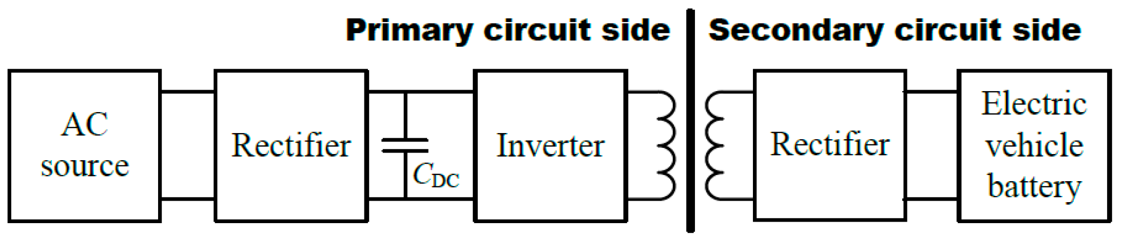
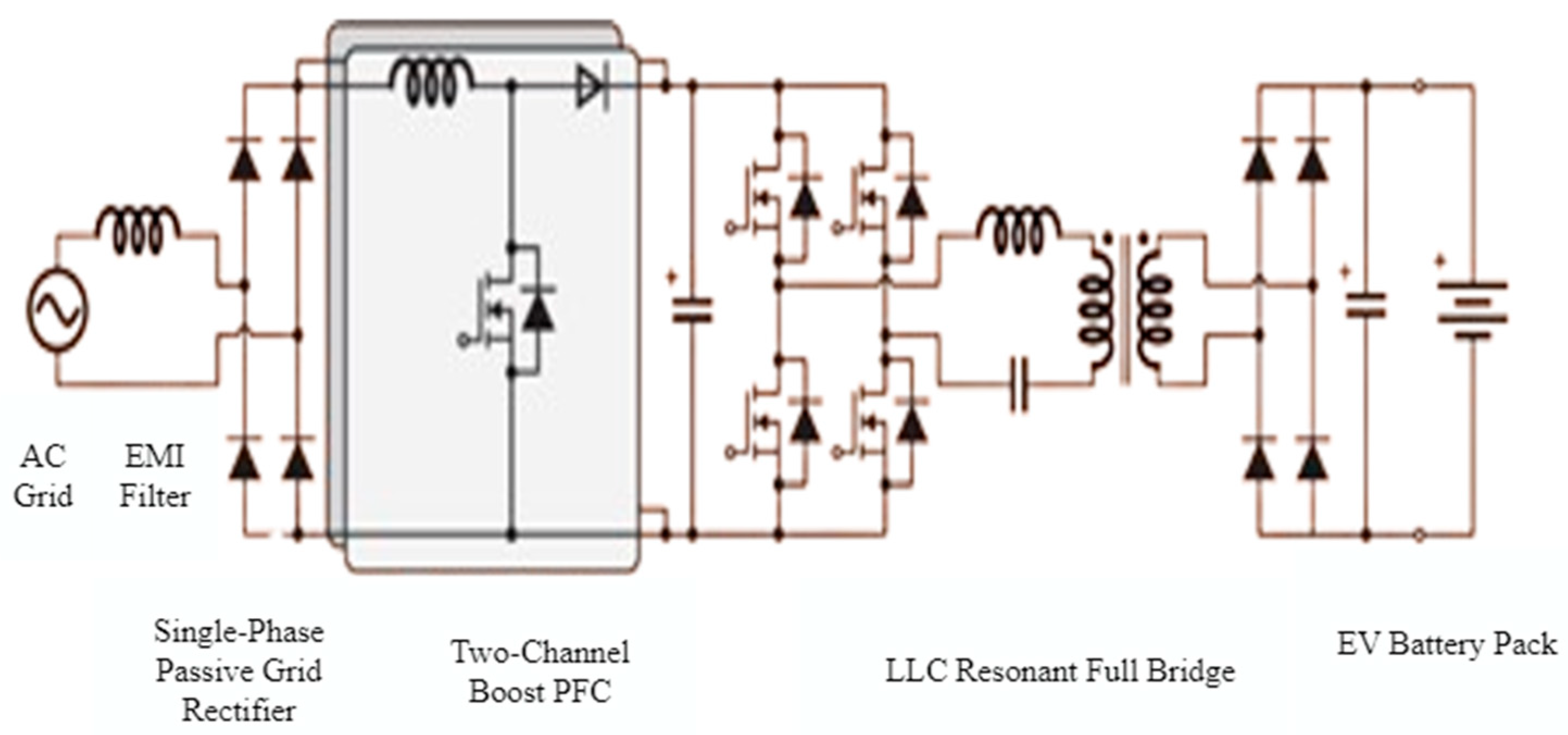
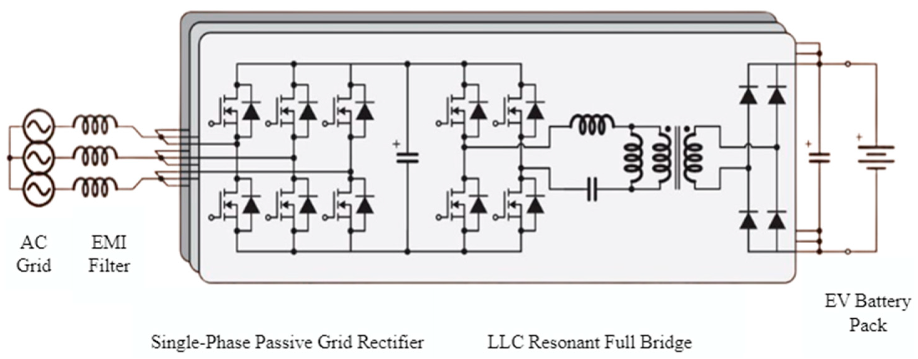
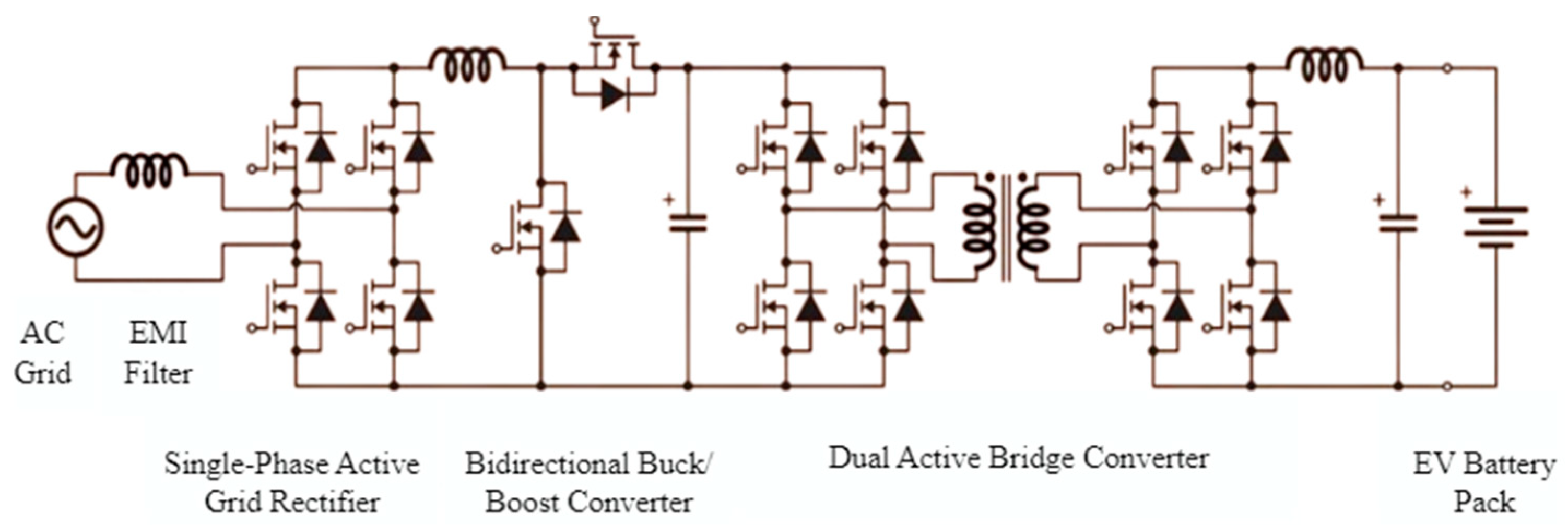
2. Power Electronics Circuit of DC Fast Charging Stations

In this section, the power electronic circuits that are fundamental to any DC fast charging system are explained. This section also provides the necessary background, technical backbone, and detailed descriptions of the components and principles of fast charging systems to understand the innovations and operational efficiencies described in Section 3.
Life safety should be a priority in power transmission devices used in EVs. The circuit architectures to be created should also be developed to ensure this security. In addition, this structure should ensure ease of maintenance. An electrically isolated circuit architecture essentially eliminates the physical conductor and reduces the risk of electric shock. This architecture is shown in its simplest form in Figure 2. According to this structure, the power received from the AC source is transmitted to the rectifier and then converted by the inverter system. The power transmitted from the primary circuit to the secondary circuit via an inductive coupling mechanism is brought to the desired level by the rectifier and transferred to the electric vehicle battery. In industrial environments and residential homes, three-phase AC welding is commonly used for providing high and consistent power output for heavy demanding applications. Three-phase AC welding also provides a more balanced power load, reduced infrastructure costs, high power output delivery for faster charging, and a scalable solution, while also ensuring compatibility with industrial standards. These features make it especially ideal for EV charging and consequently, many EV charging stations charge using a three-phase AC source [6,7].
The DC link capacitor can be eliminated to reduce system size and cost. Thus, charging stations are designed at lower costs. Additionally, performing energy conversions within the vehicle will reduce the weight at the charging station [7].
A model of the circuit architecture described above is illustrated in Figure 3. In this configuration, a single-phase AC source is used. The signal is first passed through an EMI filter to reduce electromagnetic interference. The filtered signal is then fed into a two-channel amplifier via a diode-bridge rectifier, which converts the AC signal to DC. This DC signal is subsequently processed by a full bridge LLC (inductor–inductor–capacitor) resonant converter, which conditions the power before transferring it to the battery. This circuit architecture is ideal for low-power charging stations designed for electric scooters, typically providing power levels of around 3.6 kW [8,9,10].
The circuit model developed by Tesla, Inc. (Austin, Texas, USA), designed for higher power operation, is shown in Figure 4. This configuration uses three-phase AC as the input. Unlike the previous circuit, this model incorporates an active rectifier to improve conversion efficiency. Similar to the previous design, an LLC resonant bridge is used to minimize conversion losses by achieving zero-voltage and zero-current switching. The output power of this system varies between 7.5 kW and 11.5 kW, depending on the phase values [9].
The circuits described above operate unidirectionally, focusing solely on EV charging. Recent studies, however, have introduced bidirectional power transfer capabilities, enabling power flow back to the charging station. The V2D (vehicle-to-device) application, depicted in Figure 5, allows power to be transferred from the vehicle battery to the charging station. This setup enables the vehicle to function as a regulator, utilizing various control algorithms to manage power flow efficiently [10].
Another model of this architecture is given in Figure 6. According to this circuit topology, the primary circuit consists of a three-phase source and three pairs of switches (Sa, Sb, Sc). Switches create AC at a higher frequency from the input to transfer power. The Sd switch pair connected in parallel to the resonant circuit is used to alleviate voltage fluctuations [11,12,13].
The current controller uses the input voltage Vx(t) via the voltage sensor, the resonant current ip(t) via the current sensor, and the secondary circuit output voltage Vo(t) to determine the correct switching frequency. Additionally, this unit maintains the resonance current amplitude with the s(t) signal [12].

3. Conceptual Overview of Proposed System

This section explains how transformerless designs can improve upon the fast charging system in the previous section by enhancing portability, reducing costs, and increasing adaptability. More specifically, this section expands the description of specific circuit components handling power management in the previous section by showing how these components can be integrated into a system that is both transformerless and modular and highlighting the practical applications and benefits of this process.
The effective operation of mobile modular DC fast charging stations for EVs depends on the comprehensive integration of communication systems and protocols. Communication systems undertake the task of ensuring a continuous and reliable data flow between the vehicle, charging station, and central servers. The ISO 15118 Standard, which is one of the basic communication systems, protocols, and standards used in EV mobile modular DC fast charging stations, is accepted as an international standard for two-way communication between EV charging stations and vehicles. This protocol includes vehicle authentication, charging session initiation, energy transfer, and secure exchange of payment information. Consequently, this standard involves the protocol for the EV to automatically authenticate and authorize itself to start charging with a secure communication link without the requirement of additional manual input from the driver. ISO 15118, with its Plug-and-Charge (PnC) feature, enables the vehicle to be automatically recognized and the charging process to start without any additional action by the user by eliminating the need for additional requirements such as RFID cards or mobile apps [13]. The ISO 15118 Standard also covers advancements for smart charging, which involves the arranging of charging speed based on grid capacity, the state of the vehicle’s battery, and the user’s choices. This process leverages to optimize energy usage and cost.
Another important protocol, the Open Source Charging Point Protocol (OCPP), organizes the data exchange of mobile modular DC fast charging stations with network operators. This protocol transfers the status of charging stations, energy usage information, and fault notifications to central servers. OCPP increases operational efficiency by facilitating remote monitoring and management of charging stations. Many central service applications are developed and offered to EV users using this protocol [14]. If it is necessary to examine communication systems in terms of communication modules and interfaces, charging stations generally communicate with central systems over broadband internet using wireless communication modules (GSM, 3G, 4G, or 5G). This connection type transmits instant status updates, energy consumption data, and fault diagnosis information of charging stations to central application servers. Charging stations that care about stable operation and data reliability use wired Ethernet interfaces for a more stable and reliable connection. Ethernet is especially preferred in applications requiring high data transfer speed and in dense charging station networks [15]. In summary, OCPP manages the operation of the charging station remotely by allowing the charging station operator to observe and check the charging station, work on remote diagnostics, update firmware, and supervise user access and billing; finally, OCPP also enables the exchange of data between the charging station and a central management system including transaction details, meter values, fault reports, and configuration changes.
Safety during charging operations is a priority for EA mobile modular DC fast charging stations. The ISO 15118 standard provides data encryption and vehicle authentication protocols during charging. These protocols are important to prevent unauthorized access and protect the confidentiality of user data. Charging stations constantly share energy management information with central systems during the charging process. This information is used for energy demand management, load balancing, and grid health analysis. This data exchange is stored to contribute to the optimization of energy distribution strategies by providing valuable insights for energy suppliers and grid operators. Data exchange enables BMSs to monitor various information during the charging process and transmit this information to the charging station, ensuring an effective charging process. One of the signals used in this process is the Control Pilot (CP) signal. The CP signal is an important communication signal that enables communication between EV charging stations and vehicles. This signal produced by the BMS is used to communicate the vehicle’s status and charging requirements to the charging station. The CP signal is usually encoded by methods such as PWM (Pulse Width Modulation) or Amplitude Modulation (AM) and is received and interpreted by the charging station. PWM is generally utilized in the charging system to control power delivery delicately. PWM also includes modulating the width of the electrical pulses sent to the device—in this case, the charger device. As an alternative method, the main purpose of using AM is to conduct different charging statuses and commands by varying the amplitude of a continuous waveform. The CP signal helps the charging station recognize the vehicle and determine the appropriate charging power. It is also used to start, stop, and safely complete the charging process. The CP signal ensures reliable transmission of continuously changing data between the vehicle and the charging station, resulting in efficient charging [16].
The communication infrastructure has enabled the development of many applications. User interfaces and mobile applications of charging stations are software that enable electric vehicle users to easily manage their charging processes and monitor their charging status. User interfaces are usually located on the charging stations themselves and can be operated via touch screens or simple buttons. To charge their vehicles, users can start, stop, or adjust charging processes using the controls on the front panel of the station. These interfaces also provide estimates of when charging will be completed and the time spent during charging [25].
Mobile applications allow users to remotely control charging stations via mobile devices such as mobile phones or tablets. Through these applications, users can find the location of the station and check the status and availability of existing charging stations. In addition, through mobile applications, users can view the map of charging stations, save their favorite charging points, and find nearby charging stations.
As a result, the mobile modular DC fast charging station infrastructures of EVs are moved to a technologically advanced level with the integration of communication systems and protocols. Standards such as ISO 15118 and OCPP enable safe and effective communication between EA mobile modular DC fast charging stations and vehicles. These protocols play a central role in critical processes such as vehicle recognition, energy transfer, and payment transactions. In addition, the wireless and wired communication infrastructures of mobile modular DC fast charging stations make it possible to transfer instant status updates and energy management information to central systems. Security and data privacy stand out as indispensable elements of the charging process. Communication methods such as CP signaling further improve the interaction between vehicles and charging stations, optimizing the process from initiation to completion of the charging process. Mobile applications and user interfaces increase the user experience and allow charging operations to be managed easily and effectively. In this context, the continuous development of EV mobile modular DC fast charging station infrastructures plays a key role in creating a sustainable transportation ecosystem. These studies contribute to the dissemination of environmentally friendly transportation solutions by encouraging the adoption of EV technology.

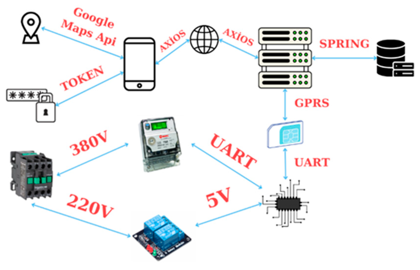
3.1. Communication and Electronic Design for Transformerless Mobile Modular DC Fast Charging Station

The system will be able to operate smoothly as the server, which is the basic building block of the system design, undertakes the information exchange and data storage processes between other devices. The communication protocols of the whole system are shown in Figure 7 [26].
The following circuits are given for embedded system software and communication embedded software. They will be operated at three different voltage levels to power the charge control card and operate other elements: 12 V for the RGB LEDs, fan, and relays, which will be mentioned in the later parts of the report; 5 V for the RB0512 DC/DC converter module; and 3.3 V for processor, GSM module, and Ethernet module. For these voltages, two separate regulators will be used that use the 12 V input value and provide 5 V and 3.3 V output voltages. The created circuit structure is shown in Figure 8 [27,28,29,30].
The most important circuit element in controlling the charging process is the microprocessor. When choosing a microprocessor, the intensity of the operations to be carried out, the operating voltage and current values of the sensors, if any, the adequacy of the communication ports, and the number of timers are important. For the controls to be carried out properly, it is important to choose a processor that works more stable than other processors and can process a large amount of data at the same time [28].
For the charging process to start, the vehicle and the charging station must communicate. This communication is provided by the CP signal coming from the BMS. According to the voltage value of the signal, the electric vehicle is not connected to the station to the processor in the control card, connected but not ready to charge, connected, ready to charge but not allowed, connected charging is ready and allowed, there is a short circuit and no power flow, or charging station unavailable commands are transmitted (Table 3) [29,30].
The op amp comparison circuit shown in Figure 9 was created to control these signal voltages. Since the supply voltages of the op amp to be used are +12 V and −12 V, the RB0512 DC/DC converter module, which provides voltage regulation from 5 V to these values, was used. The PWM signal generated by the processor is compared with the CP signal coming from the BMS [26,27,28]. Here, the duty cycle ratio of the PWM signal will determine the charging current. The CP_READ value obtained at the op amp output will be monitored on the processor. Depending on the CP_READ value, the necessary commands for charging will be given (Figure 9).
The processor will start or stop charging based on the CP_READ value. This process will be carried out using a contactor. A switch pin connected to the processor will be used for contactor control. To start the charging process, the optocoupler will be triggered by giving a trigger from the switch pin. The main reason for using an optocoupler here is to provide electrical insulation. When the optocoupler is turned on, the D9 LED will also light and a trigger will be observed. When the optocoupler is triggered, the transistor inside it will reach saturation and the Q2 transistor will also switch to conduction. By using a relay with a DC trigger voltage of 12 V, the contactor will operate with AC triggering [27]. When the contactor is triggered, the neutral connected to the grid will switch from NO (normal open) to NC (normal close) position, and the charging process will begin. The D7 diode parallel to the relay was used to protect against any induced current that the coil in the relay structure could create at the time of triggering [32,33,34].
An example of a 50 A 2s BMS slave circuit is shown in Figure 10 below. Recent advances in the literature and recent developments regarding batteries have shown that using standard Si Mosfets and new generation GaN Mosfets as switching elements provides very positive effects on BMS performance [34].
Even if the DC fast charger electronic infrastructure is designed, it is very important to ensure communication between the mobile application and the server for data communication. In this way, users can instantly access up-to-date information and track their charging status.
The system established to provide this information can be described under several headings as follows.
(1)
The required vehicle information will be transmitted to the charging station through the communication pins located in the two sockets of the charging cable.
(2)
Thanks to the smart meter contained in the charging station, how much power is transferred to the vehicle can be measured instantly. This power data will be transferred to the charging station’s motherboard through the data transfer port of the smart meter.
(3)
The data contained in the charging station will be transferred to the server via the GSM module that communicates with the motherboard of the charging station.
(4)
Thanks to the website prepared for users who own charging stations, it will be possible to change the electricity price determined by distribution companies at any time. The determined electricity price will be transferred to the server and the amount to be paid will be calculated according to the power drawn by the users and their consumption.
(5)
All these collected data will be combined on the server and transferred to the mobile software over the internet to be displayed to the user. In this way, users will be able to see all information instantly [35].

3.2. Battery Technical Features

This section explains the critical role of advanced battery technologies in developing battery-assisted DC fast charging stations. The section also focuses on enhancing the infrastructure to support rapid charging capabilities while alleviating the related demands and impacts on the electrical grid.

3.2.1. Battery Cell Type

Li-ion batteries are a type of rechargeable battery that undergo redox reactions, enabling them to store electric energy. These batteries comprise four essential components crucial for these chemical reactions: cathode active materials, anode active materials, electrolyte, and a separator. During the charging and discharging processes, lithium ions traverse a porous membrane (separator) and shuttle between the anode and cathode using an electrolyte containing lithium salts. The active materials facilitate the movement of lithium ions via intercalation, a process dictated by their crystalline structure that allows them to fit within designated spaces and either accept or release electrons. During charging, lithium ions deintercalate from the positive electrode and intercalate into the negative electrode, while the current flows through the negative electrode to the positive electrode [36,37]. Conversely, during discharge, lithium ions migrate from the negative electrode to the positive electrode, and electrons move in the same direction through the electrical connection, as illustrated in Figure 11.
Equation (1) represents the reaction occurring on the positive electrode during the charging and Equation (2) illustrates the reaction occurring at the negative electrode during the discharging process:
LiMO2 → xLi+ + xe + Li1−xMO2
LiC6 → Li1−xC6 + xLi+ + xe
An electric vehicle is powered by a battery pack weighing hundreds of kilograms, formed by an assembly of thousands of battery cells. These batteries can utilize different types of battery cells in terms of shape, size, and cathode chemistry. In electric vehicles, there are three main types of battery cells based on their shape: cylindrical, prismatic, and pouch cells. Cylindrical cells are produced by winding the elements inside the cell like a roll, placing them inside a metal casing, filling this space with electrolyte, and inserting the terminal at the end. In prismatic and pouch cells, the battery elements such as the anode and cathode are folded on top of each other or stacked instead of being wound like a roll.

3.2.2. Battery Cathode Chemistry

Cathode active materials in lithium-ion batteries typically include metal oxides like mixed metal oxides or phosphate derivatives [38,39,40]. These include lithium nickel manganese cobalt oxide (NMC, LiNixMnyCozO2), known for its longer life cycle, lithium iron phosphate (LFP, LiFePO4), which reduces the risk of thermal runaway, lithium nickel cobalt aluminium oxide (NCA, LiNixCoyAlzO2), lithium cobalt oxide (LCO, LiCoO2), and lithium manganese oxide (LMO, LiMn2O4), which offers higher charging rates and thermal stability. These cathode materials exhibit superior characteristics in terms of energy density, power density, safety, stability, and cost. However, a material that perfectly meets all requirements has yet to be developed. Users should prioritize their specific needs and choose a battery that excels in the desired feature [41,42,43]. Meanwhile, anode active materials commonly include graphite, hard carbon, graphene, and other carbon-based materials. Additionally, compounds based on LiTiO2, known as titanite (LTO), serve as anode active materials [44].

3.2.3. Lithium Cobalt Oxide (LCO)

Initially commercialized by Sony in 1991, LiCoO2 offers a straightforward synthesis process and boasts high specific energy (ranging from 150 to 240 Wh/kg) [45]. However, it comes with drawbacks such as shorter cycle life, toxic tendencies, high cost, and utilization of only 50% of its theoretical capacity. Additionally, LiCoO2 experiences rapid capacity degradation under high voltage (>4.4 V) and intense current density conditions. To address these issues and achieve cost-effective, high-energy, durable, and safe cathodes, LiMyCo1−yO2 materials, where M represents metals, were developed. These metals can include Ni, Al, Mg, Fe, Mn, Ti, Zn, Cr, B, Rh, and other transition metals from the periodic table [46].

3.2.4. Lithium Nickel Manganese Cobalt Oxide (LiNixMnyCozO2, NMC)

NMC, a relatively recent breakthrough in cathode technology, has gained widespread adoption over LCO in many large-scale applications within the consumer electronics industry. It boasts a specific energy range of 150–250 Wh/kg, making it particularly well-suited for electric vehicles and other applications due to its adjustable power density, strong safety profile, extended lifespan, and adequate energy density [19,20,47].
LiNixCoyMn1−x−yO2, derived by reducing the cobalt content in commercial LCO cathode materials while increasing other transition metals like Mn and Ni, forms the basis of NMC cathode materials. The presence of cobalt, nickel, and manganese in NMC cathodes creates a battery that offers a blend of high current density, substantial capacity, and structural integrity, respectively. This unique combination of attributes has made NMC cathodes highly versatile and widely utilized in Li-ion batteries. Furthermore, NMC’s energy density is contingent on its stability at elevated cut-off voltages (>4.5 V) [19]. Different compositions of NMC exist based on varying stoichiometric ratios of elements, such as NMC(111), NMC(433), NMC(532), NMC(622), and NMC(811), each influencing factors like cost, capacity, and thermal stability [20].

3.2.5. Lithium Iron Phosphate (LiFePO4, LFP)

LiFePO4, characterized by its phosphorus olivine structure, contrasts with NMC’s layered metal oxides in terms of cathode chemistry. This structure reduces the risk of thermal runaway due to oxygen deficiency. It features a discharge potential of 3.4 V and a theoretical capacity of 170 mAhg−1. However, its specific energy is lower due to the reduced driving force (lower discharge voltage value). Despite this, its standout attribute is the cathode’s stability during cycling, which safeguards the battery from thermal runaway. Additionally, it boasts a longer lifespan and better charging rates compared to LiCoO2, albeit at the expense of lower energy density [21].

3.2.6. Lithium Nickel Cobalt Aluminium (NCA)

An NCA battery comprises 80% nickel, 15% cobalt, and 5% aluminium. While it shares similarities with NMC, it stands out for incorporating aluminium instead of manganese. With a specific energy ranging from 200 to 260 Wh/kg, the inclusion of aluminium enhances its energy density and stability to some extent. However, this cathode active material also comes with drawbacks like reduced safety and increased cost. Despite these limitations, it is suitable for electric vehicle applications due to its high energy density [22].

3.2.7. Lithium Manganese Oxide, Spinel (LMO, LiMn2O4)

LMO exhibits excellent power capabilities, rapid charging speeds, and thermal resilience. Nonetheless, it falls short in terms of energy capacity compared to LiCoO2 batteries and tends to have a reduced lifespan in elevated temperatures. While it may not match the longevity of other lithium-ion chemistries, LMO remains suitable for certain applications, especially those prioritizing power performances over extended cycle life.

3.2.8. Cell Type Selection

Selecting the appropriate battery cell is crucial as it serves as the fundamental unit impacting the overall performance of the battery module. Typically, battery cell assembly adheres to the “barrel principle”, where the capacity of the entire battery pack is dictated by the cell with the lowest capacity within the group. This necessitates consistency in cell type, model, capacity, internal resistance, and voltage, ensuring that these parameters do not deviate by more than 2% to maintain optimal performance.
Li-ion battery cells might be utilized in various structures, including pouch, cylindrical, and prismatic configurations in a battery package. There are several advantages and disadvantages of these configurations as depicted in Table 4 [11,16,23]. Cylindrical cells in battery technology offer a compact design with high energy density, efficient manufacturing processes, and enhanced safety due to their structural features, including reduced thickness and high protection. These cells require fewer units in a battery pack, contributing to their efficiency and effectiveness in various applications. For these reasons, the use of cylindrical cells has been considered for the battery-assisted DC fast charging station.

3.2.9. Battery Package for DC Charging Station

LFP has significant advantages over NMC and other cathode active compounds. These include its high thermal stability, no issue with staying at 100% charge in electric vehicles due to its low voltage, much longer lifespan compared to NMC cathode batteries, and its ability to be used in larger cell designs due to emitting less heat than NMC. Therefore, within the scope of this project, we aim to use cylindrical cells and an LFP cathode active material.
To achieve the desired voltage and capacity values in the battery pack and manage numerous battery cells safely and efficiently, cells are assembled in modules and packs. In our system, each module will be designed to contain 15 cells in series and 8 cells in parallel. Thus, one module will have a capacity of 54 V–40 Ah (2160 Wh). To reach the desired 400 V for the design, connecting eight of these modules in series and two in parallel will be sufficient. This will result in a final battery capacity of 432 V and 80 Ah.
Alternatively, an 800 V option can be planned. In this case, by connecting the same modules (54 V–40 Ah) in 16 series and 2 parallel configurations, it will be possible to fast charge two vehicles simultaneously.
The designed battery-assisted DC charging station offers various advantages in terms of power conversion and communication system. Firstly, by using the algorithm created for the station, power can be received from the grid in the range of 22/25 kW, providing up to 200 kW of supply. This feature allows electric vehicles in the system to be charged simultaneously at up to 75 kW each, using a dual connector connection (CCS2) for charging operations. The algorithm also efficiently stores electric energy by charging the battery during low-cost tariff periods, reducing the amount of electricity received from the grid and mitigating fluctuations that may occur in the distribution grid.
The system also stands out with its communication capability. In instances where electric vehicles are not being charged, the battery management system used to meet the daily electricity demand at the location of the charging station ensures the healthy operation of the system and carries out battery discharge processes. This minimizes the risk of disruptions to the grid in grid-connected systems.
The system primarily aims to prevent possible adverse scenarios without affecting the grid, minimize fluctuations in the distribution grid, and reduce transformer congestion, bulkiness, and costs, which are significant advantages of these systems. Additionally, the cylindrical LFP cathode type used in the battery cell aims to extend battery life and reduce battery infrastructure renewal downtime by half. Furthermore, cost savings will be achieved by eliminating the need for infrastructure revisions, additional cable usage, and transformer requirements for existing charging stations. For distribution companies, the installation of these systems is crucial. Particularly, reducing the time and cost-related expenses during the charging station installation process, conducting battery charging at reasonable times from the grid, and minimizing the risk of disrupting the grid in case of system malfunctions will enable distribution companies to demonstrate a positive outlook at regional and national levels. Implementing environmentally friendly and innovative technologies with this system will contribute to global and national carbon reduction goals.

3.2.10. Possible Contributions of AI (Artificial Intelligence) and ML (Machine Learning) Approaches for Battery-Assisted DC Fast Charging Systems

The integration of AI and ML approaches for battery-assisted DC fast charging systems can further enhance the operational efficiency, reliability, and scalability of these systems [17,18,48,49,50,51,52,53,54,55,56,57,58,59,60]. The main contributions of AI and ML approaches can be summarized as follows:
  • Predictive Maintenance: AI and ML models can be utilized to predict battery health and the need for maintenance or replacement of charging station components based on historical data and real-time monitoring. Consequently, this enhances the reliability and longevity of the charging infrastructure, decreases downtime, and reduces maintenance costs. However, as a possible limitation, these models can require high-quality data for accurate predictions and initial setup and integration can be complex and resource-intensive. As an example, regression models and neural networks can predict the remaining useful life (RUL) of batteries by learning from historical operational data and charge/discharge cycles.
  • Demand Prediction: Taking historical charging data and other relevant variables such as time of day, day of the week, or local events into account, ML and AI models can predict demand at charging stations. Naturally this further leverages the energy management and ensures that adequate resources are accessible during peak times without overstraining the grid. But again as a limitation, prediction accuracy can be affected by unexpected external variables and factors. Specifically, time-series-based models such as LSTM (Long-Short Term Memory) and RNN (Recurrent Neural Network) can be utilized for estimating future charging station usage.
  • Optimal Charging Planning: These models can be deployed to plan the charging process by balancing the load on the grid and maximizing the usage of renewable energy sources. This can further increase grid stability and maximizes the use of cheaper and greener energy sources. However, the model for that task frequently requires real-time sample information and can be complicated to implement in systems with multiple variables. Specifically, RL (Reinforcement Learning) models can be trained to find the optimal charging strategy for minimizing cost and charging time while maximizing battery life.
  • Battery Management and Health Monitoring: Deep learning models can be implemented to observe the state of health (SoH) and state of charge (SoC) of batteries to maximize their usage and prevent overcharging or deep discharging issues. But again, these models can highly rely on the quality of sensor information and can be computationally intensive. Support Vector Machines (SVM), Convolutional Neural Networks (CNNs), and Recurrent Neural Networks (RNNs) are generally deployed to analyze voltage, current, and temperature data to assess battery conditions continuously for this task.

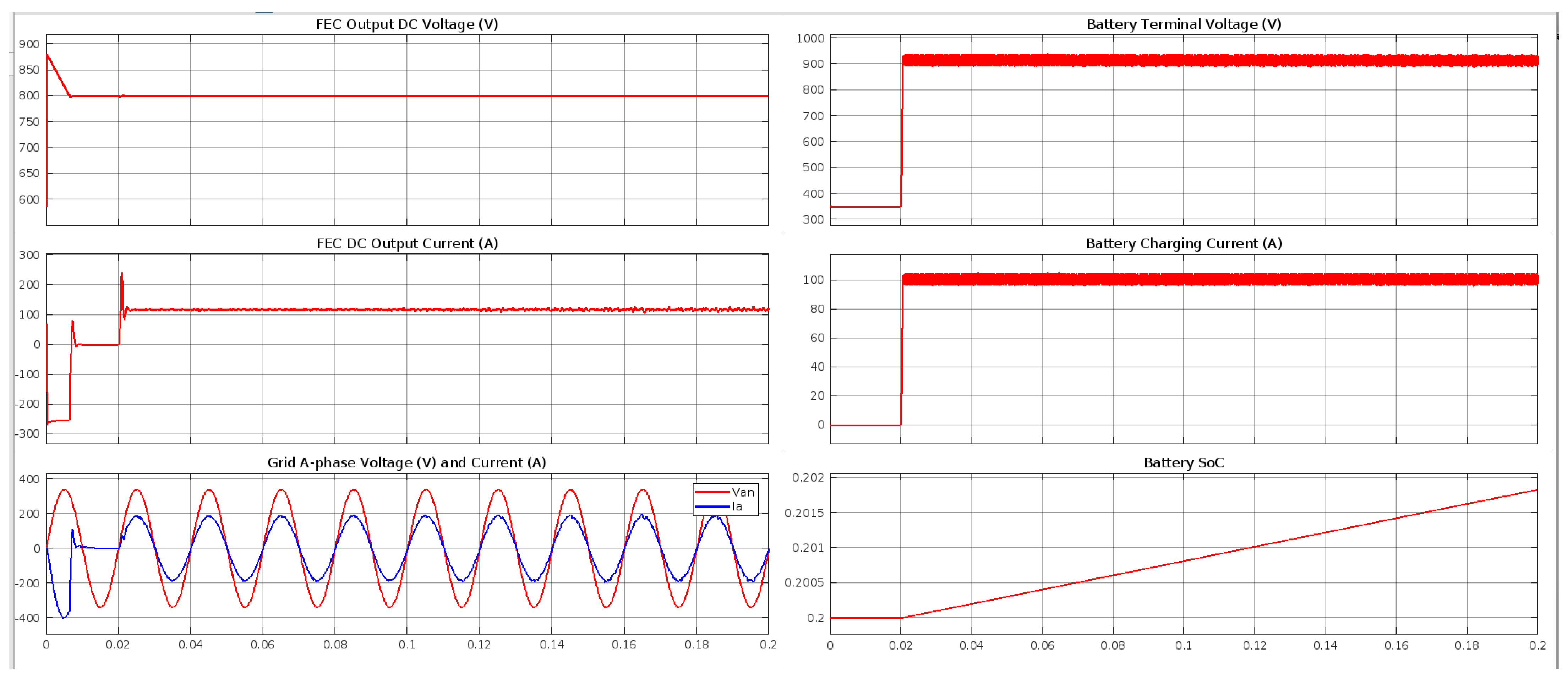
4. DC Fast Charging Station Modelling and Control

The fast charging unit requires a DC connection, and managing this DC connection is crucial. Various voltage control schemes for DC bars are available, with Master–Slave and Droop Control being the most used. Typically, the voltage of the DC connection is adjusted based on the mains voltage. However, in this study, the DC connection voltage can be regulated independently of the mains voltage. This regulation can be achieved according to the ratio of the battery’s cutoff voltage and the modulation index of the battery charger. The stability of the DC bar with the inverter output connection relies on the size of the capacitor, which affects the fluctuations in the DC current value. These fluctuations can be significant due to the potential connection of numerous EV chargers to the bar, necessitating a high capacitor value. To determine the appropriate DC capacitor value, the formula presented as Equation (6) should be used. Key points include that the maximum current and voltage values at the specified DC charging level serve as the reference values for the battery’s current and voltage. This assignment is crucial because the specified EV cannot exceed its maximum power value. The formula for calculating the power of an EV is given by Equation (3) below.
P = V m a x I m a x
The importance of calculating the apparent power lies in its ability to determine the load coefficient within the power system, the power drawn from the number of charging slots available for EV connections, and the system’s power factor. This ensures that the active and reactive power requirements of the system are adequately met. The formula for calculating the apparent power is provided in Equation (4) below.
V i s i b l e p o w e r = k l o a d N c o r e P m a x cos Φ
The capacitor on the DC bus is essential for maintaining voltage fluctuations within a certain range, especially since multiple EV chargers can be connected to the DC bar, causing variability in the fluctuation current. When the switching state is low (BUCK), the switching block at the bottom of the output terminal shorts the DC connection to the negative end, making the voltage ideally zero. Conversely, when the switching state is high (BOOST), the switching block becomes active, and the output voltage ideally matches the positive end of the DC connection, equating to the Vdc parameter. The appropriate DC bar capacitor value and DC bar voltage can be calculated using the equations provided in (5) and (6).
V d c V a , m i n m m i n
C d c = A 2 n T ( Δ G ) ( cos Φ ) ( V d c ) 2 ( Δ V )
After the calculation, in the modeling of a DC fast charging station connected to the battery pack of an Electric Vehicle (EV), the main components are as follows:
  • Grid: Model the AC supply voltage as a three-phase constant voltage source.
  • DC Fast Charging Station: Model the power electronic circuits that convert the AC supply voltage from the grid to the DC voltage level required by the EV battery pack.
    Filter & AC Measurements to filter the harmonics in the line current and measure the three-phase supply voltage and line current.
    Unity Power Factor (UPF) Front End Converter (FEC) to control output DC voltage at 800 V.
    Two-level and three-level inverter fidelity.
    Isolated DC-DC converter supplies constant charging current to the EV battery.
  • EV Battery Pack: Model the battery pack as a series of battery cells.
This setup ensures an accurate representation of the DC fast charging process, focusing on the conversion and regulation of voltage levels necessary for efficient EV battery charging (Figure 12).
Input parameters of the designed Matlab Simulink model are THDi (Total Harmonic Distortion Current) 5–25%, RAF (Reduction Factor) 20%, PEA (Power of Electric Vehicle) 90 kW, kload (Overload Factor) 1.1, cos φ (Power Factor), 0.95, T (Period for AC Voltage) 0.01 s, n 0.5, fsw (Switch Frequency) 80 kHz, Three-Phase Short-Circuit Level 1200 MVA, Phase-Phase Voltage (Vrms) 340 kV, and Frequency 50 Hz. Accordingly, the output parameters are A (Apparent Power) 1050 kVAR, ∆G (Power Changing Range) 10%, ∆V (Voltage Range) 20%, Cdc (DC Bar Capacity) 0.018 F, Vdc (DC bar Voltage) 800 V, Cf (Filter Capacitor) 0.000165 F, L_inv (Inverter Inductance) 0.00048 H, L_grid (Grid Inductance) is specified as 0.00069 H, and Rs (Damping Resistor) 1.31 Ω. Provided that these parameters are within the scope of standards, the simulation was carried out by selecting different values for the model to be designed. After designing the model, it is important to determine the simulation sampling and time values to simulate the model. Making the right decisions regarding these is necessary for the simulation to be carried out. According to these parameters, the results obtained are shared in Figure 13.
According to the results of the analyses, the DC bus voltage is stable at 800 V, the obtained charging voltage is 917.3786 V, and the obtained charging current is 101.2455 A. Figure 14 illustrates the (up) Battery terminal voltage and Battery charging current, and (below) DC output current and Grid A-phase voltage and current.
As seen in Figure 14, the battery terminal voltage is approximately 917 V and the battery charging current is approximately 101 A. Also, the DC output current and the Grid A-phase voltage and current are gathered very well as desired for EV battery fast charging.

5. Conclusions and Future Works

To encourage the widespread adoption of electric vehicle technology and increase its benefits, the proliferation of mobile DC fast charging stations is crucial. As a general summary of this study, DC charging stations, which aim to reduce charging times while expanding the charging infrastructure, are presented with circuit topologies and battery technologies. Although charging stations should be placed in a strategic location where the electrical grid is robust and can support them effectively, in many locations of the grid, the transformer capacity cannot support a charging station above 150 kW. The portable DC fast charging station, for which literature summary and development suggestions are presented in this study, draws as little as 22 kW from the grid and provides energy that can charge vehicles in 10–15 min with powers in the range of 200–450 kW. For this purpose, it stores the energy it draws from the grid for a long time in small amounts in batteries. During the electric vehicle charging process, the master–slave BMS structure works in harmony with the communication system, and the parallel serial connection structure between the battery cells is changed. Thus, the DC voltage and power required by the vehicle can be provided with less loss and fewer power electronic components. Establishing a charging station network of this proposed structure will not only facilitate the widespread use of DC electric vehicle charging station systems but also protect the network against potential overloads.
This study investigates the current literature on battery-assisted DC fast chargers and presents findings regarding the feasibility of this proposed solution. In future studies, the battery system to be installed can be powered by renewable energy sources. Although there are studies on this in the literature, planning has generally been carried out off-grid. However, network improvement can be made without drawing electrical energy from the grid or by withdrawing the remaining electrical energy for storage from the grid. By installing a two-way metering system (vehicle-to-grid, V2G), excess stored electricity can be transferred to the grid.

Author Contributions

Conceptualization, A.A. and E.B.; methodology, A.A., B.A. and S.O.; software, S.O.; validation, M.G., A.A., B.A. and E.B.; formal analysis, S.G. and E.B.; investigation, S.O.; resources, A.A.; data curation, E.B.; writing–original draft preparation, S.O.; writing–review and editing, E.B.; visualization, S.O.; supervision, E.B. and S.G.; project administration, A.A.; funding acquisition, A.A. and S.G. All authors have read and agreed to the published version of the manuscript.

Funding

This research received no external funding.

Data Availability Statement

The original contributions presented in the study are included in the article, further inquiries can be directed to the corresponding author.

Acknowledgments

This research was conducted collaboratively by the MOBILERS team at Sivas Cumhuriyet University and the Battery Research Group at Sivas University of Science and Technology (SBTU).

Conflicts of Interest

The authors declare no conflicts of interest.

References

  1. Singh, B.; Verma, A.; Chandra, A.; Al-Haddad, K. Implementation of Solar PV-Battery and Diesel Generator Based Electric Vehicle Charging Station. IEEE Trans. Ind. Appl. 2020, 56, 4007–4016. [Google Scholar] [CrossRef]
  2. Paudel, D.; Das, T.K. Das A deep reinforcement learning approach for power management of battery-assisted fast-charging EV hubs participating in day-ahead and real-time electricity markets. Energy 2023, 283, 129097. [Google Scholar] [CrossRef]
  3. Cui, D.; Wang, Z.; Liu, P.; Wang, S.; Dorrell, D.G.; Li, X.; Zhan, W. Operation optimization approaches of electric vehicle battery swapping and charging station: A literature review. Energy 2023, 263, 126095. [Google Scholar] [CrossRef]
  4. Kokchang, P.; Chattranont, N.; Menaneatra, T.; Phetriang, N.; Lertmanokul, C.; Nateprapai, N.; Chaitusaney, S.; Larbwisuthisaroj, S.; Srianthumrong, S. Economic Feasibility of Hybrid Solar-Powered Charging Station with Battery Energy Storage System in Thailand. Int. J. Energy Econ. Policy 2023, 13, 342–355. [Google Scholar] [CrossRef]
  5. Jain, V.; Singh, B. A Grid Connected PV Array and Battery Energy Storage Interfaced EV Charging Station. IEEE Trans. Transp. Electrif. 2023, 9, 3723–3730. [Google Scholar] [CrossRef]
  6. Aydin, E.; Aydemir, M.T.; Aksoz, A.; El Baghdadi, M.; Hegazy, O. Inductive Power Transfer for Electric Vehicle Charging Applications: A Comprehensive Review. Energies 2022, 15, 4962. [Google Scholar] [CrossRef]
  7. Hassoune, A.; Khafallah, M.; Hassoune, A.; Khafallah, M.; Mesbahi, A.; Bouragba, T. Power Management Strategies of Electric Vehicle Charging Station Based Grid Tied PV-Battery System Abdelouahed Mesbahi Ecole Nationale Supérieure d’Electricité et de Mécanique de Casablanca Power Management Strategies of Electric Vehicle Charging Station Based Grid Tied PV-Battery System. 2018. Available online: https://www.researchgate.net/publication/325999800 (accessed on 4 June 2024).
  8. Ataseven, I.; Sahin, I.; Ozturk, S.B. Design and Implementation of a Paralleled Discrete SiC MOSFET Half-Bridge Circuit with an Improved Symmetric Layout and Unique Laminated Busbar. Energies 2023, 16, 2903. [Google Scholar] [CrossRef]
  9. Tan, X.; Qu, G.; Sun, B.; Li, N.; Tsang, D.H.K. Optimal scheduling of battery charging station serving electric vehicles based on battery swapping. IEEE Trans Smart Grid 2019, 10, 1372–1384. [Google Scholar] [CrossRef]
  10. Lan, Y.; Benomar, Y.; Deepak, K.; Aksoz, A.; El Baghdadi, M.; Bostanci, E.; Hegazy, O. Switched reluctance motors and drive systems for electric vehicle powertrains: State of the art analysis and future trends. Energies 2021, 14, 2079. [Google Scholar] [CrossRef]
  11. Oyucu, S.; Doğan, F.; Aksöz, A.; Biçer, E. Comparative Analysis of Commonly Used Machine Learning Approaches for Li-ion Battery Performance Prediction and Management in Electric Vehicles. Appl. Sci. 2024, 14, 2306. [Google Scholar] [CrossRef]
  12. Wang, Y.; Aksoz, A.; Geury, T.; Ozturk, S.B.; Kivanc, O.C.; Hegazy, O. A review of modular multilevel converters for stationary applications. Appl. Sci. 2020, 10, 7719. [Google Scholar] [CrossRef]
  13. Mültin, M. ISO 15118 as the Enabler of Vehicle-to-Grid Applications. In Proceedings of the 2018 International Conference of Electrical and Electronic Technologies for Automotive, Milan, Italy, 9–11 July 2018; pp. 1–6. [Google Scholar]
  14. Garofalaki, Z.; Kosmanos, D.; Moschoyiannis, S.; Kallergis, D.; Douligeris, C. Electric vehicle charging: A survey on the security issues and challenges of the open charge point protocol (OCPP). IEEE Commun. Surv. Tutor. 2022, 24, 1504–1533. [Google Scholar] [CrossRef]
  15. El Ghanam, E.; Hassan, M.; Osman, A.; Ahmed, I. Review of communication technologies for electric vehicle charging management and coordination. World Electr. Veh. J. 2021, 12, 92. [Google Scholar] [CrossRef]
  16. Yahaya, A.A.; Edpuganti, A.; Khadkikar, V.; Zeineldin, H. A Novel Simultaneous AC and DC Charging Scheme for Electric Vehicles. IEEE Trans. Energy Convers. 2024. Early Access. [Google Scholar] [CrossRef]
  17. Lombardo, T.; Duquesnoy, M.; El-Bouysidy, H.; Årén, F.; Gallo-Bueno, A.; Jørgensen, P.B.; Bhowmik, A.; Demortière, A.; Ayerbe, E.; Alcaide, F.; et al. Artificial intelligence applied to battery research: Hype or reality? Chem. Rev. 2021, 122, 10899–10969. [Google Scholar] [CrossRef]
  18. Shibl, M.; Ismail, L.; Massoud, A. Electric vehicles charging management using machine learning considering fast charging and vehicle-to-grid operation. Energies 2021, 14, 6199. [Google Scholar] [CrossRef]
  19. Şen, M.; Özcan, M.; Eker, Y.R. A review on the lithium-ion battery problems used in electric vehicles. Next Sustain. 2024, 3, 100036. [Google Scholar] [CrossRef]
  20. Xia, Y.; Zheng, J.; Wang, C.; Gu, M. Designing principle for Ni-rich cathode materials with high energy density for practical applications. Nano Energy 2018, 49, 434–452. [Google Scholar] [CrossRef]
  21. Hadouchi, M.; Koketsu, T.; Hu, Z.; Ma, J. The origin of fast-charging lithium iron phosphate for batteries. Battery Energy 2002, 1, 20210010. [Google Scholar] [CrossRef]
  22. Julien, C.M.; Mauger, A. NCA, NCM811, and the Route to Ni-Richer Lithium-ion Batteries. Energies 2020, 13, 6363. [Google Scholar] [CrossRef]
  23. Stavropoulos, P.; Sabatakakis, K.; Bikas, H. Welding Challenges and Quality Assurance in Electric Vehicle Battery Pack Manufacturing. Batteries 2024, 10, 146. [Google Scholar] [CrossRef]
  24. Tu, H.; Feng, H.; Srdic, S.; Lukic, S. Extreme fast charging of electric vehicles: A technology overview. IEEE Trans. Transp. Electrif. 2019, 5, 861–878. [Google Scholar] [CrossRef]
  25. Majidpour, M.; Qiu, C.; Chung, C.Y.; Chu, P.; Gadh, R.; Pota, H.R. Fast demand forecast of electric vehicle charging stations for cell phone application. In Proceedings of the 2014 IEEE PES General Meeting|Conference & Exposition, National Harbor, MD, USA, 27–31 July 2014; pp. 1–5. [Google Scholar]
  26. Aksoz, A.; Song, Y.; Saygin, A.; Blaabjerg, F.; Davari, P. Improving performance of three-phase slim DC-link drives utilizing virtual positive impedance-based active damping control. Electronics 2018, 7, 234. [Google Scholar] [CrossRef]
  27. Ogan, S.E.; Bostanci, E. Capacitor sizing of three-level neutral point clamped voltage source inverter for electric vehicles: Effects of modulation and motor characteristics. IET Power Electron. 2024. Early View. [Google Scholar] [CrossRef]
  28. Unsal, D.B.; Aksoz, A.; Oyucu, S.; Guerrero, J.M.; Guler, M. A Comparative Study of AI Methods on Renewable Energy Prediction for Smart Grids: Case of Turkey. Sustainability 2024, 16, 2894. [Google Scholar] [CrossRef]
  29. Oyucu, S.; Dümen, S.; Duru, I.; Aksöz, A.; Biçer, E. Discharge Capacity Estimation for Li-ion Batteries: A Comparative Study. Symmetry 2024, 16, 436. [Google Scholar] [CrossRef]
  30. Aksoz, A. An optimized overcurrent protection study using enough number of sfcl at optimal points of a distributed real city grid. Teh. Vjesn. 2021, 28, 104–112. [Google Scholar] [CrossRef]
  31. Özden, S.; Dursun, M.; Aksöz, A.; Saygın, A. Prediction and Modelling of Energy Consumption on Temperature Control for Greenhouses. J. Polytech. 2018, 22, 213–217. [Google Scholar] [CrossRef]
  32. Yilmaz, E.N.; Polat, H.; Oyucu, S.; Aksoz, A.; Saygin, A. Data storage in smart grid systems. In Proceedings of the 2018 6th International Istanbul Smart Grids and Cities Congress and Fair (ICSG), Istanbul, Turkey, 25–26 April 2018; Institute of Electrical and Electronics Engineers Inc.: New York, NY, USA, 2018; pp. 110–113. [Google Scholar] [CrossRef]
  33. Yilmaz, E.N.; Aksoz, A.; Saygin, A. Design of an off-grid model of micro-smart grid connection of an asynchronous motor fed with LUO converter. Electr. Eng. 2018, 100, 2659–2666. [Google Scholar] [CrossRef]
  34. Al Wahedi, A.; Bicer, Y. Comprehensive Review of Recent Electric Vehicle Charging Stations. 2021. Available online: https://www.academia.edu/97732945/Comprehensive_Review_of_Recent_Electric_Vehicle_Charging_Stations (accessed on 4 June 2024).
  35. Al Wahedi, A.; Bicer, Y. Development of an off-grid electrical vehicle charging station hybridized with renewables including battery cooling system and multiple energy storage units. Energy Rep. 2020, 6, 2006–2021. [Google Scholar] [CrossRef]
  36. Shchegolkov, A.V.; Komarov, F.F.; Lipkin, M.S.; Milchanin, O.V.; Parfimovich, I.D.; Shchegolkov, A.V.; Semenkova, A.V.; Velichko, A.V.; Chebotov, K.D.; Nokhaeva, V.A. Synthesis and study of cathode materials based on carbon nanotubes for Lithium-ion batteries. Inorg. Mater. Appl. Res. 2021, 12, 1281–1287. [Google Scholar] [CrossRef]
  37. Liu, Y.; Jiang, J.; Yuan, Y.; Jiang, Q.; Yan, C. Vertically aligned NiCo2O4 nanosheet-encapsulated carbon fibers as a self-supported electrode for superior Li+ storage performance. Nanomaterials 2019, 9, 1336. [Google Scholar] [CrossRef]
  38. Shchegolkov, A.V.; Lipkin, M.S.; Shchegolkov, A.V.; Korbova, E.V.; Lipkina, T.V.; Lipkin, V.M. On the mechanism of formation of electrochromic WO3 films on the surface of Sn, Ti, ITO electrodes in the process of cathodic electrodeposition. Inorg. Mater. Appl. Res. 2022, 13, 1605–1614. [Google Scholar] [CrossRef]
  39. Shchegolkov, A.V.; Lipkin, M.S.; Shchegolkov, A.V. Preparation of WO3 films on titanium and graphite foil for fuel cell and supercapacitor applications by electrochemical (cathodic) deposition method. Russ. J. Gen. Chem. 2022, 92, 1161–1167. [Google Scholar] [CrossRef]
  40. Amarasekara, A.S.; Wang, D.; Shrestha, A.B. Efficient leaching of metal ions from spent Li-ion battery combined electrode coatings using hydroxy acid mixtures and regeneration of lithium nickel manganese cobalt oxide. Batteries 2024, 10, 170. [Google Scholar] [CrossRef]
  41. Chikkannanavar, S.B.; Bernardi, D.M.; Liu, L. A review of blended cathode materials for use in Li-ion batteries. J. Power Sources 2014, 248, 91–100. [Google Scholar] [CrossRef]
  42. Uzun, D.; Dogrusoz, M.; Mazman, M.; Bicer, E.; Avci, E.; Sener, T.; Kaypmaz, T.C.; Cakan, R.D. Effect of MnO2 coating on layered Li(Li0.1Ni0.3Mn0.5Fe0.1)O2 cathode material for Li-ion batteries. Solid State Ion. 2013, 249, 171–176. [Google Scholar] [CrossRef]
  43. Mazman, M.; Çuhadar, Ö.; Uzun, D.E.; Avcı,, E.; Bicer, E.; Kaypmaz, T.C.; Kadiroğlu, Ü. Optimization of LiFePO4 synthesis by hydrothermal method. Turk. J. Chem. 2014, 38, 297. [Google Scholar] [CrossRef]
  44. Goriparti, S.; Miele, E.; De Angelis, F.; Di Fabrizio, E.; Zaccaria, R.P.; Capiglia, C. Review on recent progress of nanostructured anode materials for Li-ion batteries. J. Power Sources 2014, 257, 421–443. [Google Scholar] [CrossRef]
  45. Choi, S.; Wang, G. Advanced Lithium-ion Batteries for Practical Applications: Technology, Development, and Future Perspectives. Adv. Mater. Technol. 2018, 3, 1700376. [Google Scholar] [CrossRef]
  46. Biçer, E.; Mazman, M.; Kaypmaz, C.; Uzun, D. Li-iyon Piller ve Uygulamaları. Nobel Yayınevi, Aralık; Nobel Yayıncılık: Ankara, Türkiye, 2021; ISBN 978-625-406-870-6. [Google Scholar]
  47. Oliveira Filho, H.R.; Zanin, H.; Monteiro, R.S.; Barbosa, M.H.P.; Teófilo, R.F. High-nickel cathodes for lithium-ion batteries: From synthesis to electricity. J. Energy Storage 2024, 82, 110536. [Google Scholar] [CrossRef]
  48. Suarez, C.; Martinez, W. Fast and ultra-fast charging for battery electric vehicles—A review. In Proceedings of the 2019 IEEE Energy Conversion Congress and Exposition (ECCE), Baltimore, MD, USA, 29 September–3 October 2019. [Google Scholar]
  49. Xie, W.; Liu, X.; He, R.; Li, Y.; Gao, X.; Li, X.; Peng, Z.; Feng, S.; Feng, X.; Yang, S. Challenges and opportunities toward fast-charging of lithium-ion batteries. J. Energy Storage 2020, 32, 101837. [Google Scholar] [CrossRef]
  50. Liu, Y.; Zhu, Y.; Cui, Y. Challenges and opportunities towards fast-charging battery materials. Nat. Energy 2019, 4, 540–550. [Google Scholar] [CrossRef]
  51. Weiss, M.; Ruess, R.; Kasnatscheew, J.; Levartovsky, Y.; Levy, N.R.; Minnmann, P.; Stolz, L.; Waldmann, T.; Wohlfahrt-Mehrens, M.; Aurbach, D.; et al. Fast charging of lithium-ion batteries: A review of materials aspects. Adv. Energy Mater. 2021, 11, 2101126. [Google Scholar] [CrossRef]
  52. Wei, Z.; Yang, X.; Li, Y.; He, H.; Li, W.; Sauer, D.U. Machine learning-based fast charging of lithium-ion battery by perceiving and regulating internal microscopic states. Energy Storage Mater. 2023, 56, 62–75. [Google Scholar] [CrossRef]
  53. Shah, A.; Shah, K.; Shah, C.; Shah, M. State of charge, remaining useful life and knee point estimation based on artificial intelligence and Machine learning in lithium-ion EV batteries: A comprehensive review. Renew. Energy Focus 2022, 42, 146–164. [Google Scholar] [CrossRef]
  54. Manoj, D.; Josh, F.T. A comprehensive review on optimization and artificial intelligence algorithms for effective battery management in EVs. Int. J. Electr. Electron. Eng. Telecommun. 2023, 12, 334–341. [Google Scholar] [CrossRef]
  55. Shibl, M.; Ismail, L.; Massoud, A. Machine learning-based management of electric vehicles charging: Towards highly-dispersed fast chargers. Energies 2020, 13, 5429. [Google Scholar] [CrossRef]
  56. Mazhar, T.; Asif, R.N.; Malik, M.A.; Nadeem, M.A.; Haq, I.; Iqbal, M.; Kamran, M.; Ashraf, S. Electric vehicle charging system in the smart grid using different machine learning methods. Sustainability 2023, 15, 2603. [Google Scholar] [CrossRef]
  57. Khawaja, Y.; Shankar, N.; Qiqieh, I.; Alzubi, J.; Alzubi, O.; Nallakaruppan, M.; Padmanaban, S. Battery management solutions for li-ion batteries based on artificial intelligence. Ain Shams Eng. J. 2023, 14, 102213. [Google Scholar] [CrossRef]
  58. Ng, M.-F.; Zhao, J.; Yan, Q.; Conduit, G.J.; Seh, Z.W. Predicting the state of charge and health of batteries using data-driven machine learning. Nat. Mach. Intell. 2020, 2, 161–170. [Google Scholar] [CrossRef]
  59. Zentani, A.; Almaktoof, A.; Kahn, M.T. A Comprehensive Review of Developments in Electric Vehicles Fast Charging Technology. Appl. Sci. 2024, 14, 4728. [Google Scholar] [CrossRef]
  60. Narasipuram, R.P.; Mopidevi, S.; Dianov, A.; Tandon, A.S. Analysis of Scalable Resonant DC–DC Converter Using GaN Switches for xEV Charging Stations. World Electr. Veh. J. 2024, 15, 218. [Google Scholar] [CrossRef]
Figure 1. EV Charging Structures [2,3].
Energies 17 03117 g001
Figure 2. AC Source-Isolated Charging Circuit Topology [7].
Energies 17 03117 g002
Figure 3. Low-power charging topology powered by single-phase AC [8].
Energies 17 03117 g003
Figure 4. 7.5–11.5 kW AC charging topology developed by Tesla, Inc. (Austin, Texas, USA). [9].
Energies 17 03117 g004
Figure 5. Circuit topology providing bidirectional power transfer [10].
Energies 17 03117 g005
Figure 6. Three-phase AC/AC converter topology [11].
Energies 17 03117 g006
Figure 7. Software protocols between charging station connectors [26].
Energies 17 03117 g007
Figure 8. Regulator circuit [27].
Energies 17 03117 g008
Figure 9. CP signal and PWM signal comparison circuit [31].
Energies 17 03117 g009
Figure 10. A preliminary design image of Slave BMS [34].
Energies 17 03117 g010
Figure 11. Schematic representation of charge and discharge process of Li-ion battery.
Energies 17 03117 g011
Figure 12. Transformerless DC Fast Charging station modeling block diagram.
Energies 17 03117 g012
Figure 13. Simulation results.
Energies 17 03117 g013
Figure 14. Battery terminal voltage and Battery charging current (up) DC output current and Grid A-phase voltage and current (below).
Energies 17 03117 g014
Table 1. IEC 61851 Standard.
Charging MethodNo. PhasesNominal Voltage (V)Max. Current (A)
ACMod 11≤250≤16
3≤480
Mod 21≤250≤32
3≤480
Mod 31≤250≤250
3≤480
DCMod 4-≤1000≤400
Table 2. AC Charge Standards and Connectors [4,5].
SAE J1772IEC 61851GB/T 20234-2TESLA
AC
Level 1
AC Level 2Modes 1Modes 2–3GB/TMobile ConnectionWall Connection
Max. Power1.9 kW19.2 kW4 kW
(13.3 kW)
8 kW
(22 kW)
7 kW
(12.8 kW)
1.9 kW
(7.7 kW)
2.8 kW
(11.5 kW)
Input Voltage120 V, single phase240 V, split phase250 V, single phase (480 V, three phase)250 V, single phase (400 V, single phase)120 V, single phase (240 V, single phase)208 V, single phase (250 V, single phase)
Max. Current16 A80 A16 A32 A32 A16/32 A
CommunicationPLCNonePLCCANCAN
RegionUSA, Japan, Republic of KoreaEurope, AustraliaChina, IndiaGlobal
Related StandardsIEC 61851-22/23
IEC 62196-2
SAE J1772-2017
IEC 61851-22/23
IEC 62196-2
GB/T 20234-2
IEC 62196-2
IEC 62196-2
Vehicle to deviceUnder DevelopmentNoNo
Plug typeEnergies 17 03117 i001Energies 17 03117 i002Energies 17 03117 i003Energies 17 03117 i004
Table 3. Charge states according to signal voltage differences [29,30].
VoltageStateExplanation
+12 VState ANo EV connected to the EVSE
+9 VState BEV connected to the EVSE, but not ready for charging
+6 VState CConnected and ready for charging, ventilation is not required
+3 VState DConnected, ready for charging, and ventilation is required
+0 VState EElectrical short to earth on the controller of the EVSE, no power supply
−12 VState FEVSE is unavailable
Table 4. Advantages and disadvantages of cell types.
Pouch CellCylindrical CellPrismatic Cell
AdvantagesThe outer structure of the cell has minimal impact since the packaging material has a low mass, allowing for high energy density in the battery.The process exhibits high maturity levels, featuring a well-developed shell structure, and it incurs low manufacturing costs.The cell offers high protection, facilitating efficient internal heat conduction through reduced single-cell thickness, leading to significantly improved safety performance. Additionally, individual cells boast high capacity, resulting in the need for fewer cells in the battery pack.
DisadvantagesLarge-capacity batteries pose challenges in the sealing process, being less reliable and more complex. The mechanical strength of the aluminum-plastic composite encapsulation film used is relatively low, limiting the battery’s service life based on the film’s lifespan.The collector may experience uneven current density distribution, leading to inconsistent responses from internal components. This can hinder the quick release of heat generated within the battery cell, potentially creating a safety hazard due to heat accumulation.The internal structure is complex, requiring high production process standards. Initially, the cells had low energy density, but there have been significant advancements in recent years, leading to major breakthroughs in this area.
Disclaimer/Publisher’s Note: The statements, opinions and data contained in all publications are solely those of the individual author(s) and contributor(s) and not of MDPI and/or the editor(s). MDPI and/or the editor(s) disclaim responsibility for any injury to people or property resulting from any ideas, methods, instructions or products referred to in the content.

