Article

Sinusoidal Rotor Core Shape for Low Torque Ripple in Hollow-Cup Machines

1
Ningbo Institute of Technology, Beihang University, Ningbo 315800, China
2
School of Instrumentation and Optoelectronic Engineering, Beihang University, Beijing 100191, China
*
Author to whom correspondence should be addressed.
Energies 2024, 17(13), 3168; https://doi.org/10.3390/en17133168
Submission received: 15 May 2024 / Revised: 21 June 2024 / Accepted: 22 June 2024 / Published: 27 June 2024

Abstract

:
Due to the configuration of coreless stators and two synchronously rotated rotors, hollow-cup machines (HCMs) enjoy the merits of negligible cogging torque and core loss. Consequently, HCMs have been successfully employed as high-speed electric machines in the aerospace field, which requires high precision and low thermal dissipation. However, the permanent magnet (PM) thickness and air-gap length of conventional HCM are uniform, resulting in various harmonics in the air-gap flux density as well as back-EMF. These harmonics inevitably produce an electromagnetic torque ripple, which has not met the increasing demand for ultraprecision in recent years. Since the inner rotor of HCMs only consists of an iron core, this paper proposes a novel sinusoidal-shaped inner rotor, which can change the harmonics of air-gap permeance, to adjust the harmonics of air-gap flux density and back-EMF. HCMs with the proposed inner rotors have a significant 87% reduction in torque ripple compared to conventional HCMs. Meanwhile, compared to conventional methods, HCMs with the proposed inner rotor exhibit comparable torque ripple and higher average torque.

1. Introduction

Ultraprecision satellites play an important role in the field of high-resolution observation. To achieve attitude stability on these satellites, attitude sensors and actuators such as magnetically suspended flywheels (MSFWs) or magnetically suspended control moment gyroscopes (MSCMGs) should be employed [1]. High-speed electric machines are usually selected as MSFW driving devices [2]. Due to high-precision demands and strict thermal conditions, high-speed electric machines for these applications should have the characteristics of high accuracy control, small vibration, and low power consumption [3].
Among various kinds of electric machines, hollow-cup machines (HCMs) have been successfully used in such applications [4,5]. The armature winding of a conventional HCM is assembled on the coreless stator. The inner rotor and outer rotor are located on different sides of the stator. Tile-shaped permanent magnets (PMs) are placed on the core of the outer rotor, and the inner rotor only consists of the rotor core. Due to the absence of the stator core, the slot-effect caused by the alternation of ferromagnetic teeth and non-magnetic slots in HCMs is negligible, resulting in low cogging torque and core loss.
However, because the thickness of PMs and inner rotor core are uniform, the air-gap flux density and back-EMF of HCMs contain abundant harmonics. Even if the phase current is sinusoidal, the interaction of phase current and back-EMF harmonics can cause perceptible electromagnetic torque ripple, leading to vibration and noise. Since the satellite platform has “ultra-stable and ultra-quiet” requirements, HCM torque ripple should be further suppressed.
Numerous studies focusing on torque ripple reduction have been carried out. Cogging torque is mainly caused by the slot effect, which can be reduced by employing the skewing method or improving the pole number combination [6,7,8]. In addition, electromagnetic torque ripples can be suppressed by reducing harmonics in the air-gap flux density, phase flux linkage, and back-EMF [9]. Applying Halbach array PMs is a potential solution. Halbach arrays are divided into several small segments, as opposed to tile-shaped PMs. The size, shape, and magnetization of each segment can be designed individually, making it possible to adjust air-gap flux density harmonics [10,11]. In [12], performance quality between HCMs with tile-shaped PMs and Halbach array PMs was compared. The machine with Halbach array PMs exhibited more sinusoidal phase back-EMF, resulting in lower torque ripple. Besides performance, more design issues were compared in [13], such as the distance between the PM and hub, hub material, winding configuration, etc. Although Halbach array PMs have many advantages, their mechanical strength is reduced, and the PM size as well as the direction of magnetization may be imperfect due to manufacturing tolerance, which negatively impacts prototype machine performance [14].
In addition, changing the PM shape can also adjust the air-gap flux density harmonics. For tile-shaped PMs, the outer and inner surfaces of a single PM are arcs, and their centers are the same. A kind of bow-shaped PM was proposed in recent years. For this PM shape, the centers of the outer and inner surfaces are different. By adjusting the distance between two centers, the harmonics of air-gap flux density can be effectively reduced [15,16]. Moreover, bow-shaped PMs can suppress total harmonic distortion (THD) of phase back-EMF [17]. Furthermore, the PM shape can be optimized by injecting harmonics based on PM thickness. For instance, when the fifth or seventh harmonic is injected, the original fifth or seventh magnetomotive force (MMF) harmonic generated by tile-shaped PMs will be suppressed, resulting in a more sinusoidal air-gap flux density and phase back-EMF [18,19].
The PM-shaping methods mentioned above can be applied to HCMs since HCMs and surface-mounted PM machines (SPMMs) have similar PM configurations. However, HCMs have limited PM thickness, which reduces the effectiveness of these methods. For example, the amplitude of injected harmonics on the PM thickness function should be small enough, or the minimum PM thickness becomes zero. In addition, PMs with complex shapes may face magnetization and manufacture problems [5].
On the other hand, torque ripples can be suppressed by adjusting the shape of the iron core. In [20], the rotor core slot in an interior PM machine (IPMM) was redesigned, resulting in an asymmetric rotor PM structure. For such a structure, the rotor core saturation was adjusted, and the torque ripple was reduced. In [21], several holes were drilled into the rotor core of an IPMM, which changed the reluctance of the rotor core, and finally suppressed torque ripple. Similarly, the end deflection of the flux barrier in a synchronous reluctance machine can be optimized to reduce torque ripple [22]. The flux barrier can be also added to the rotor tooth of a switched reluctance machine, which can adjust the winding inductance and suppress torque ripple [23]. Nevertheless, the existing literature seldom considers the optimization of the rotor core in SPMMs because the the rotor core surface is covered by PMs. As for HCMs, the inner rotor only has an iron core, meaning that the shape of the inner rotor core can be optimized.
This paper proposes a novel sinusoidal-shaped inner rotor to reduce HCM torque ripples. By injecting harmonics into the thickness function of the inner rotor core, the inner rotor surface becomes uneven, changing the permeance of the air-gap. Consequently, the sinusoidal-shaped inner rotor can adjust the harmonics of the air-gap flux density and suppress torque ripples. The paper is organized as follows: Section 2 introduces the topology and principle of the proposed inner rotor shape. Section 3 analyzes the influences of injected harmonics on machine performance. Section 4 compares the effectiveness of the proposed inner rotor shape with conventional methods. In Section 5, the theoretical analysis is validated through experiments. Finally, conclusions are provided in Section 6.

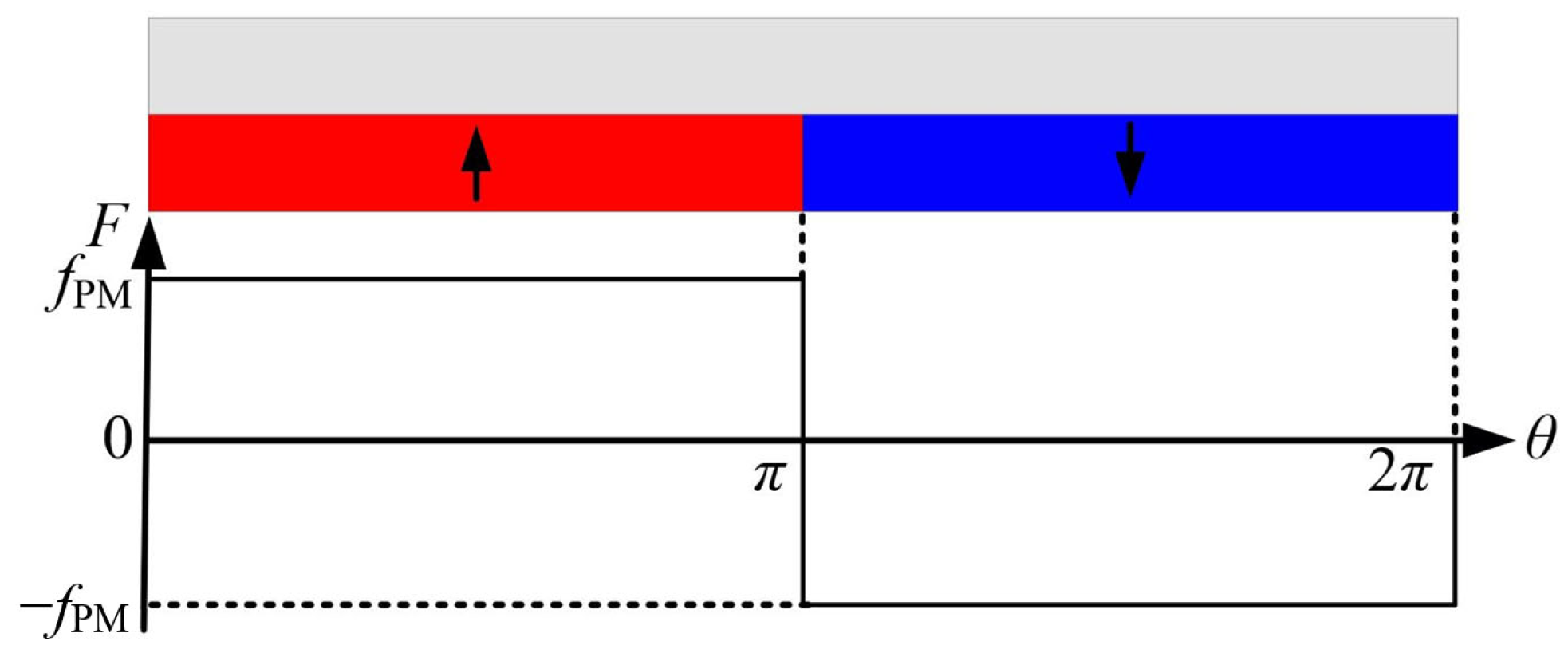
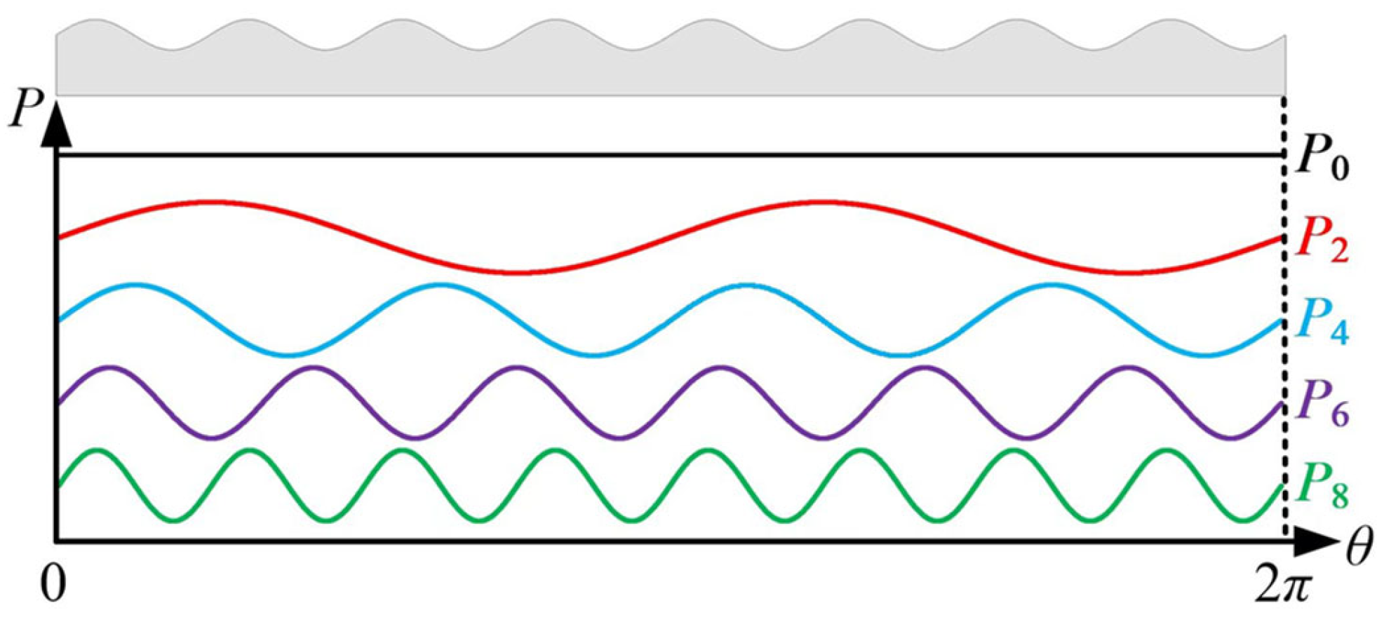
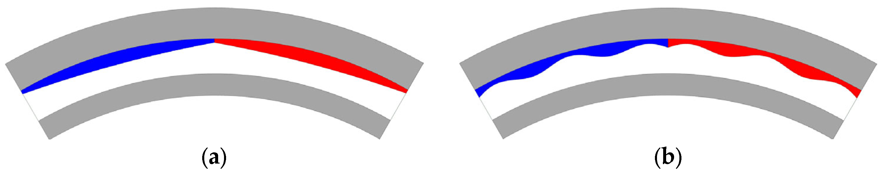
2. Topology and Principle of Proposed Inner Rotor Shape

The topology of conventional HCMs is shown in Figure 1. To analyze the harmonic orders of air-gap flux density, an MMF permeance model introduced in [24] was employed. For simplicity, flux leakage and magnetic resistance of the iron core were neglected in the model. Figure 2 shows the simplified air-gap MMF generated by tile-shaped PMs; its Fourier expansion FPM can be expressed as:
F PM = k = 1 4 f PM ( 2 k 1 ) π cos ( 2 k 1 ) θ π 2
where fPM is the magnitude of the air-gap MMF waveform, and θ represents the circumferential position in the air-gap. As can be deduced, in one pole-pair region, there exist abundant odd-order harmonics in the PM-generated air gap MMF. Since the inner rotor thickness in the conventional HCM is uniform, the air gap permeance P0 only has the DC component p0, as expressed in Equation (2). The open-circuit air-gap flux density B0 can be obtained by multiplying FPM and P0, as shown in Equation (3), indicating that the conventional HCM has various odd-order harmonics in the open-circuit air-gap flux density and back-EMF. When the machine is excited by sinusoidal phase current, the torque ripple is induced due to the fifth and seventh back-EMF harmonics.
P 0 = p 0
B 0 = k = 1 4 f PM p 0 ( 2 k 1 ) π cos ( 2 k 1 ) θ π 2
The torque ripple is caused by back-EMF harmonics, whereas back-EMF harmonics are influenced by air-gap flux density harmonics. Hence, torque ripples can be suppressed by adjusting the harmonics of air-gap flux density. As shown in Figure 3, the inner rotor core thickness is a function of circumferential position. By injecting harmonics into the inner rotor core thickness function, the air-gap length becomes uneven and induces harmonics in the air-gap permeance. Assuming that the air-gap permeance has the mth harmonic Pm, the expression would be:
P m = p m cos ( m θ + θ m )
where pm and θm represent the amplitude and phase of Pm. Then, the open-circuit air-gap flux density Bm produced by the interaction of FPM and Pm can be deduced as:
B m = k = 1 2 f PM p m ( 2 k 1 ) π cos α 1 + cos α 2 α 1 = ( 2 k 1 m ) θ π / 2 θ m α 2 = ( 2 k 1 + m ) θ π / 2 + θ m
Equation (5) infers that the (2k − 1)th harmonic of FPM and mth harmonic of air-gap permeance will produce the (2k − 1 ± m)th harmonics of air-gap flux density. Moreover, the amplitudes and phases of air-gap flux density harmonics will vary with the amplitudes and phases of air-gap permeance harmonics. For instance, Table 1 lists the harmonic order of air-gap flux density produced by several PM-generated air-gap MMF and air-gap permeance harmonics. The higher the harmonic order, the lower the amplitude. Hence, this paper only considers the first, third, fifth, and seventh PM-generated air-gap MMF harmonics (designated FPM1, FPM3, FPM5, and FPM7, respectively). Injecting the second, fourth, sixth, or eighth harmonics (designated P2, P4, P6, and P8 shown in Figure 3, respectively) into the air-gap permeance produces the fifth and seventh harmonics of air-gap flux density, which may effectively suppress torque ripples. Therefore, this paper mainly focuses on these four injected harmonics. However, it should be noted that if the machine is assembled with consequent-pole PMs, the PM-generated air-gap MMF will contain even-order harmonics. In this case, the odd-order harmonics of air-gap permeance can be injected to produce the extra fifth and seventh air-gap flux density harmonics.
The harmonic injection of air-gap permeance is realized by changing the shape of the inner rotor core. As shown for each pole-pair region in Figure 4, the sixth harmonic is injected into the thickness function of the inner rotor core. Then, the shape of the inner rotor core becomes sinusoidal and the air-gap length thickness function exists in the sixth harmonic.

3. Influence of Injected Harmonics on Machine Performance

This section analyzes the influence of the proposed inner rotor shape on different injected harmonics using the 2D finite element (FE) method. The basic parameters of HCMs are listed in Table 2. To reveal the influence injected harmonics have on machine performance, the inner rotor core thickness was modelled as a trigonometric function. By adjusting the trigonometric function parameters, the harmonic order, amplitude, and phase of air-gap permeance harmonics were changed. During the analysis, harmonics of different orders were injected individually. To keep a minimum mechanical air-gap length, the maximum thickness of the inner rotor core was fixed.

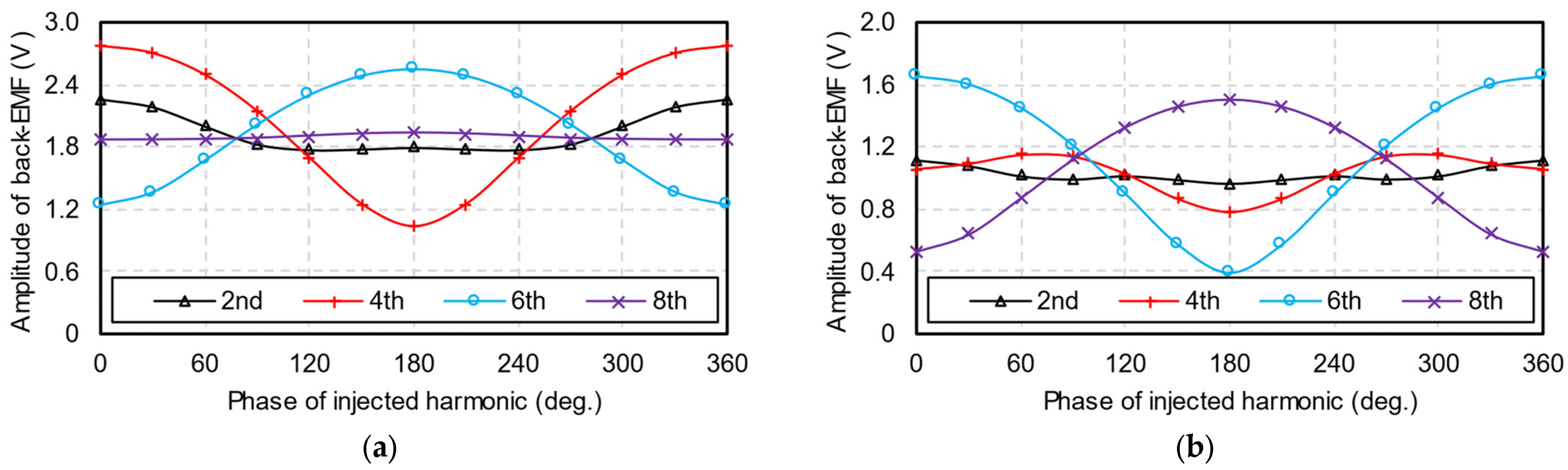
3.1. Phases of Injected Harmonics

Figure 5 and Figure 6 show the influences of injected harmonics on the fifth and seventh back-EMF harmonics. The amplitudes of the injected harmonics are fixed at 1.2 mm. The phases and amplitudes of back-EMF harmonics are successfully adjusted by varying the phases of injected harmonics. The fifth and seventh back-EMF harmonic phases in conventional HCMs are −90°. When the phases of injected harmonics are 0° or 180°, the phases of fifth and seventh back-EMF harmonics remain −90°, indicating that injected harmonics in these two phases only influence the amplitudes of fifth and seventh back-EMF harmonics.
On the other hand, as shown in Table 1, several interactions can produce the fifth harmonic of air-gap flux density, i.e., interactions between FPM1 and P4, FPM1 and P6, FPM3 and P2, FPM3 and P8, etc. The seventh harmonic of air-gap flux density can be produced by interactions between FPM1 and P6, FPM1 and P8, FPM3 and P4, FPM5 and P2, etc. Since FPM1 is the fundamental component of PM-generated air-gap MMF, its amplitude is much larger than FPM3 and FPM5. Therefore, as shown in Figure 5 and Figure 6, the fifth back-EMF harmonic is mainly influenced by the fourth and sixth injected harmonics, whereas the seventh back-EMF harmonic is mainly influenced by the sixth and eighth injected harmonics.
Figure 7 shows the influences of injected harmonics on torque performance. Both average torque and torque ripples vary with injected harmonic phases. As previously mentioned, the fourth, sixth, and eighth injected harmonics have significant influences on the fifth or seventh back-EMF harmonics. Thus, these three injected harmonics can effectively adjust the torque ripple, while the second injected harmonic’s influence on the torque ripple is minimal.

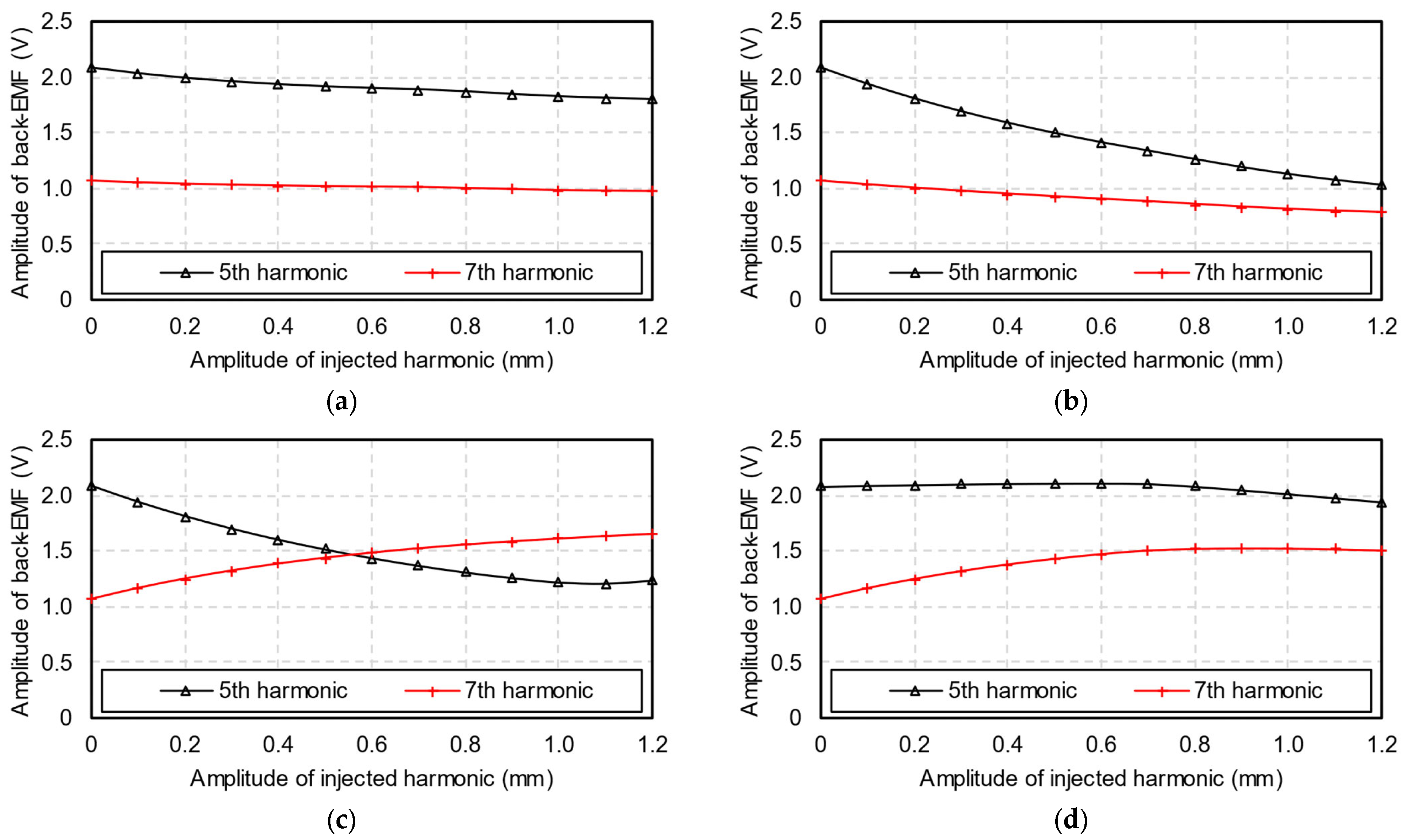
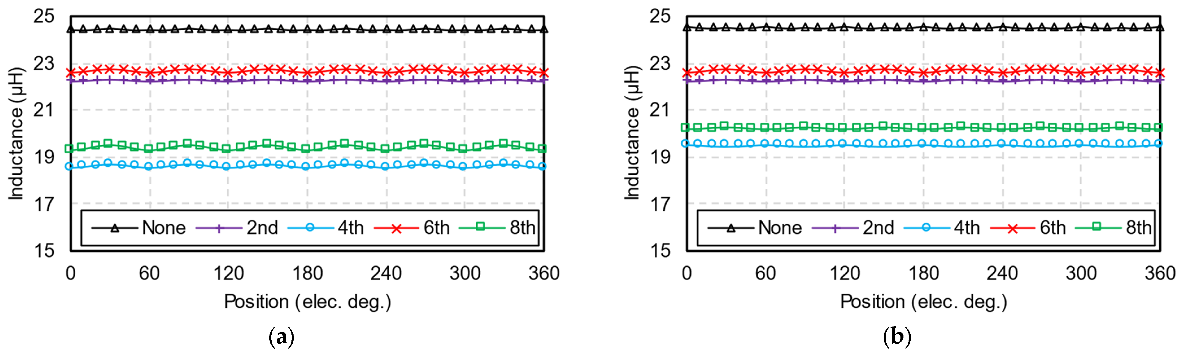
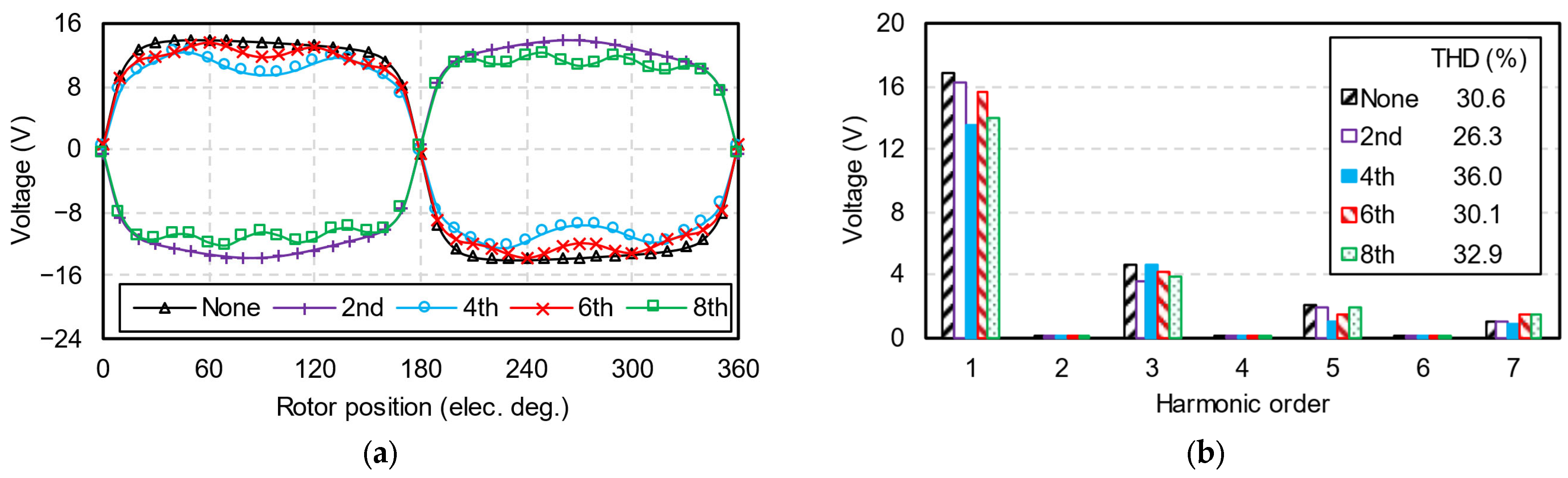
3.2. Amplitudes of Injected Harmonics

Figure 8 shows the relationship between the amplitudes of phase back-EMF harmonics and the amplitudes of injected harmonics. The second, fourth, sixth, and eighth injected harmonic phases are fixed at 180°, 180°, 0°, and 180°, respectively. As the second injected harmonic’s amplitude increases, the back-EMF harmonics slightly reduce. An increase in the fourth injected harmonic reduces both the fifth and seventh back-EMF harmonics. When the sixth injected harmonic increases, the fifth back-EMF harmonic is suppressed while the seventh back-EMF harmonic is enhanced. Furthermore, as the amplitude of the eighth injected harmonic increases, both the fifth and seventh back-EMF harmonics increase to their maximum value first before decreasing.
Figure 9 shows the relationship between torque performance and the amplitude of injected harmonics. As the amplitude of injected harmonics increases, the equivalent air-gap length also increases, reducing the average torque.
In addition, when the amplitudes of the fifth and seventh back-EMF harmonics are equal, torque ripple reaches the minimum. These observations can be analyzed as follows. Assume the fundamental three-phase back-EMFs e1A, e1B, and e1C are expressed as:
e 1 A = E 1 cos θ e π / 2 e 1 B = E 1 cos θ e π / 2 2 π / 3 e 1 C = E 1 cos θ e π / 2 + 2 π / 3
where E1 is the amplitude of the fundamental component of back-EMF, and θe is the electrical rotor position. The sinusoidal three-phase currents iA, iB, and iC can be expressed as:
i A = I 1 cos θ e π / 2 + φ i B = I 1 cos θ e π / 2 2 π / 3 + φ i C = I 1 cos θ e π / 2 + 2 π / 3 + φ
where I1 is the amplitude of phase current, and φ is the current angle. The three-phase fifth back-EMF harmonics e5A, e5B, and e5C and seventh back-EMF harmonics e7A, e7B, and e7C are expressed as:
e 5 A = E 5 cos 5 θ e π / 2 e 5 B = E 5 cos 5 θ e π / 2 + 2 π / 3 e 5 C = E 5 cos 5 θ e π / 2 2 π / 3
e 7 A = E 7 cos 7 θ e π / 2 e 7 B = E 7 cos 7 θ e π / 2 2 π / 3 e 7 C = E 7 cos 7 θ e π / 2 + 2 π / 3
where E5 and E7 represent the amplitudes of fifth and seventh back-EMF harmonics, respectively. The torques created by the fundamental components of back-EMF T1, fifth back-EMF harmonic T5, and seventh back-EMF harmonic T7 can be written as:
T 1 = e 1 A i A + e 1 B i B + e 1 C i C / Ω
T 5 = e 5 A i A + e 5 B i B + e 5 C i C / Ω
T 7 = e 7 A i A + e 7 B i B + e 7 C i C / Ω
where Ω is the angular velocity. By substituting Equations (6)–(9) into Equations (10)–(12), the torques can be derived as:
T 1 = 1.5 E 1 I 1 cos φ / Ω
T 5 = 1.5 E 5 I 1 cos 6 θ e π + φ / Ω
T 7 = 1.5 E 7 I 1 cos 6 θ e φ / Ω
When the Id = 0 control strategy is employed, i.e., φ = 0, T5 and T7 have opposite phases. Hence, when the fifth and seventh back-EMF harmonics have the same amplitudes, the torques caused by these two harmonics are cancelled by each other, resulting in the lowest torque ripple.

3.3. Best Injected Harmonic

To determine the best inner rotor shape for HCMs, the parameters of four injected harmonics were optimized, and their corresponding machine performances were compared. Using the sixth injected harmonic as an example, torque performance under different injected harmonic parameters is calculated in Figure 10. When the machine exhibits the lowest torque ripple, the corresponding amplitudes and phases of the injected harmonics were selected as the optimized values. Table 3 summarizes the optimized parameters for four injected harmonics.
Figure 11 compares the open-circuit air-gap flux densities of HCMs, where conventional HCMs without harmonic injection are designated as None. Due to the increased equivalent air-gap length, the fundamental components of four machines with injected harmonics are decreased. Due to the injected harmonics, these machines show different characteristics of air-gap flux density harmonics. For instance, the machine injected with the sixth harmonic exhibits an air-gap density that is 31% lower than the fifth harmonic, but 40% higher than the seventh harmonic compared to conventional HCMs. Consequently, the amplitudes of the fifth and seventh air-gap flux density harmonics in this machine are similar.
The open-circuit inductances of five machines are shown in Figure 12. Compared to conventional HCMs, HCMs with sinusoidal inner rotors exhibit lower inductances due to increased equivalent air-gap lengths. Moreover, the uneven air-gap length also leads to differences between d-axis and q-axis inductances, especially for machines injected with fourth and eighth harmonics. This finding indicates that when the d-axis current is not zero, these HCMs produce reluctance torque and their average torque may increase. However, the Id ≠ 0 condition can also cause higher torque ripples.
Figure 13 compares the phase back-EMFs of five machines. Due to the coreless stator and full-pitch winding, phase back-EMF waveforms are similar to open-circuit radial air-gap flux density waveforms. Since injecting the second harmonic suppresses the third back-EMF harmonic, the corresponding HCM had the lowest THD, whereas the THDs of the other four machines are higher than 30%. Due to high THD, these machines still have trapezoidal back-EMF waveforms.
Figure 14 shows the on-load phase voltages of these HCMs. The waveforms and spectra of on-load voltages and back-EMFs are similar due to their small winding resistance and inductance. In this paper, the power supply is assumed to be an ideal sinusoidal current source. For actual applications, the voltage or current injected into the machine contains various harmonics. These harmonics not only increase the THD of on-load voltage, but may cause different electromagnetic phenomena and influence the proposed HCMs’ optimized design, which will be investigated in the future.
The torque performances of five HCMs are shown in Figure 15 and Table 4. Compared to conventional HCMs, four machines with injected harmonics reduce torque ripples. As shown in Figure 8 and Figure 9, by injecting the sixth harmonic, the amplitudes of the fifth and seventh back-EMF harmonics can be adjusted equally since its influence on the fifth and seventh back-EMF harmonics is the opposite. Consequently, the HCM with the sixth injected harmonic has the lowest sixth torque harmonic and, thus, the lowest torque ripple. The residual 12th torque harmonic is caused by the 11th and 13th back-EMF harmonics, which can be suppressed by injecting the 12th air-gap permeance harmonic. The effectiveness of injecting the second harmonic is minimal. Although injecting the fourth and eighth harmonics partly reduce torque ripple, they decrease the average torque by 18%–20%. Overall, injecting the sixth harmonic is the best choice for torque ripple suppression, since it only causes a 7% drop in average torque.

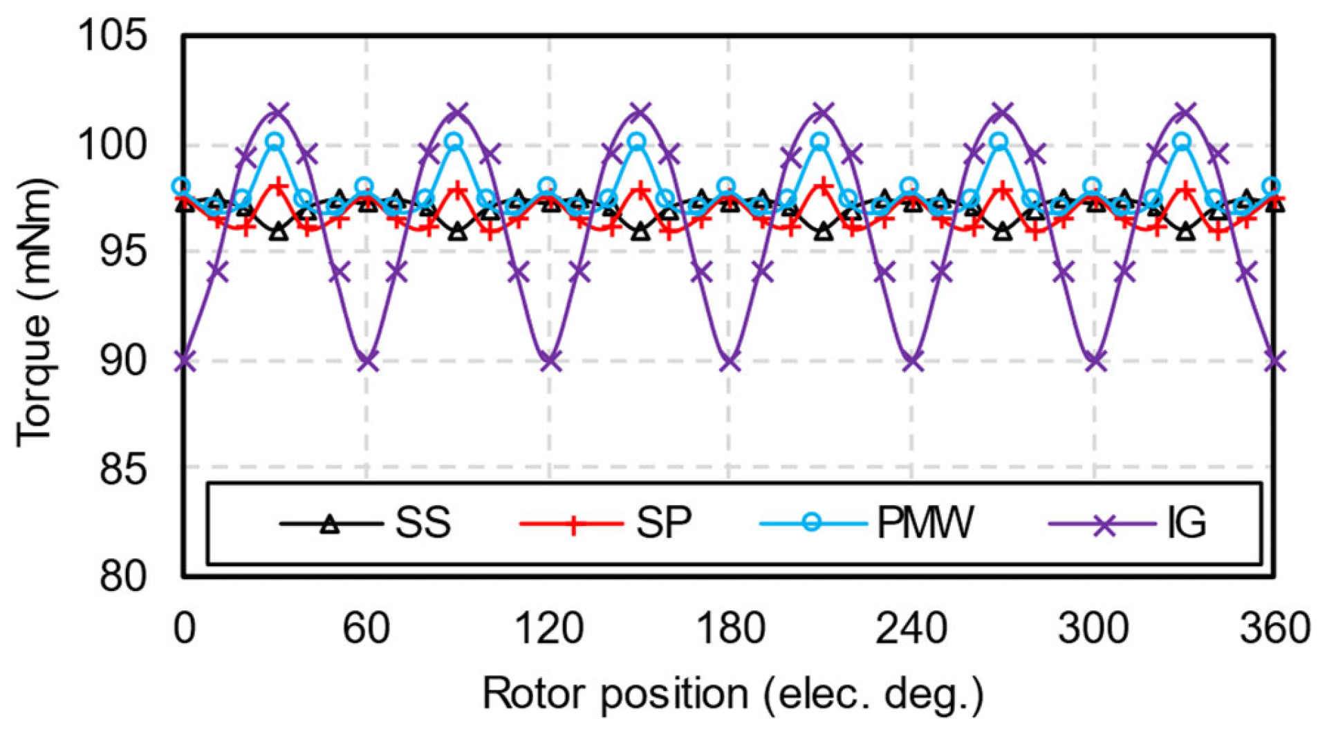
4. Electromagnetic Performance Comparison

To confirm the superiority of the proposed sinusoidal-shaped inner rotor, this section compares machine performances between the proposed inner rotor and conventional methods. The PM-shaping methods presented in [15,16,17,18] are illustrated in Figure 16. To simplify the expression, the HCM with the sixth harmonic injected into the inner rotor is designated as IR-6, while the HCM with a bow-shaped PM is designated as PM-B. Meanwhile, HCMs with fifth and seventh harmonics injected into PMs are designated PM-5 and PM-7, respectively.
Figure 17 compares the torque waveforms of HCMs with proposed inner rotor and PM-shaping methods. In addition to PM-shaping methods, some conventional methods can suppress torque ripple, such as skewing the slots, shortening the winding pitch, reducing PM width, and increasing air-gap lengths, which are designated as SS, SP, PMW, and IG in this section, respectively. Figure 18 shows the torque waveforms of HCMs using conventional methods. Table 5 summarizes the torque characteristics of these machines. Compared to conventional methods, the sinusoidal-shaped inner rotor proposed in this paper not only suppresses torque ripple but also has a relatively higher average torque.

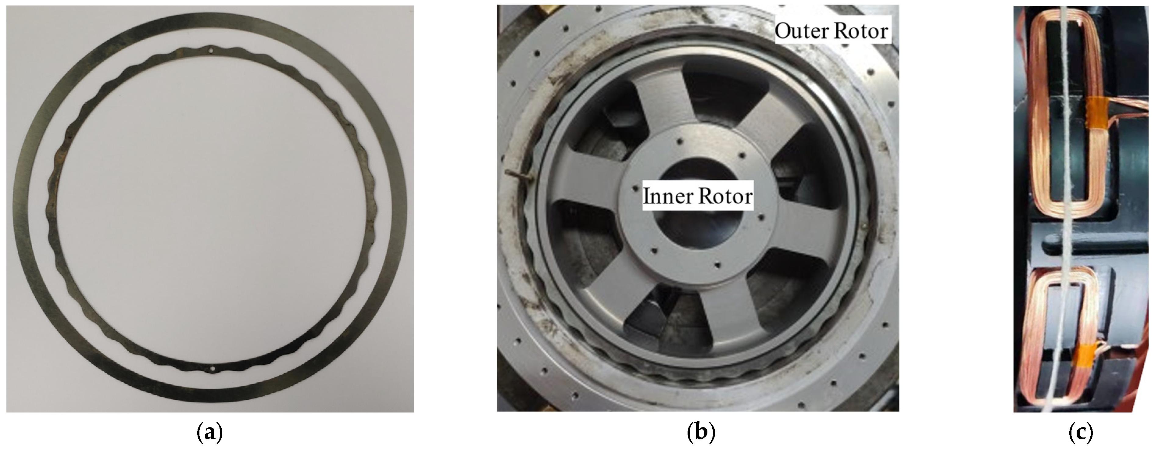
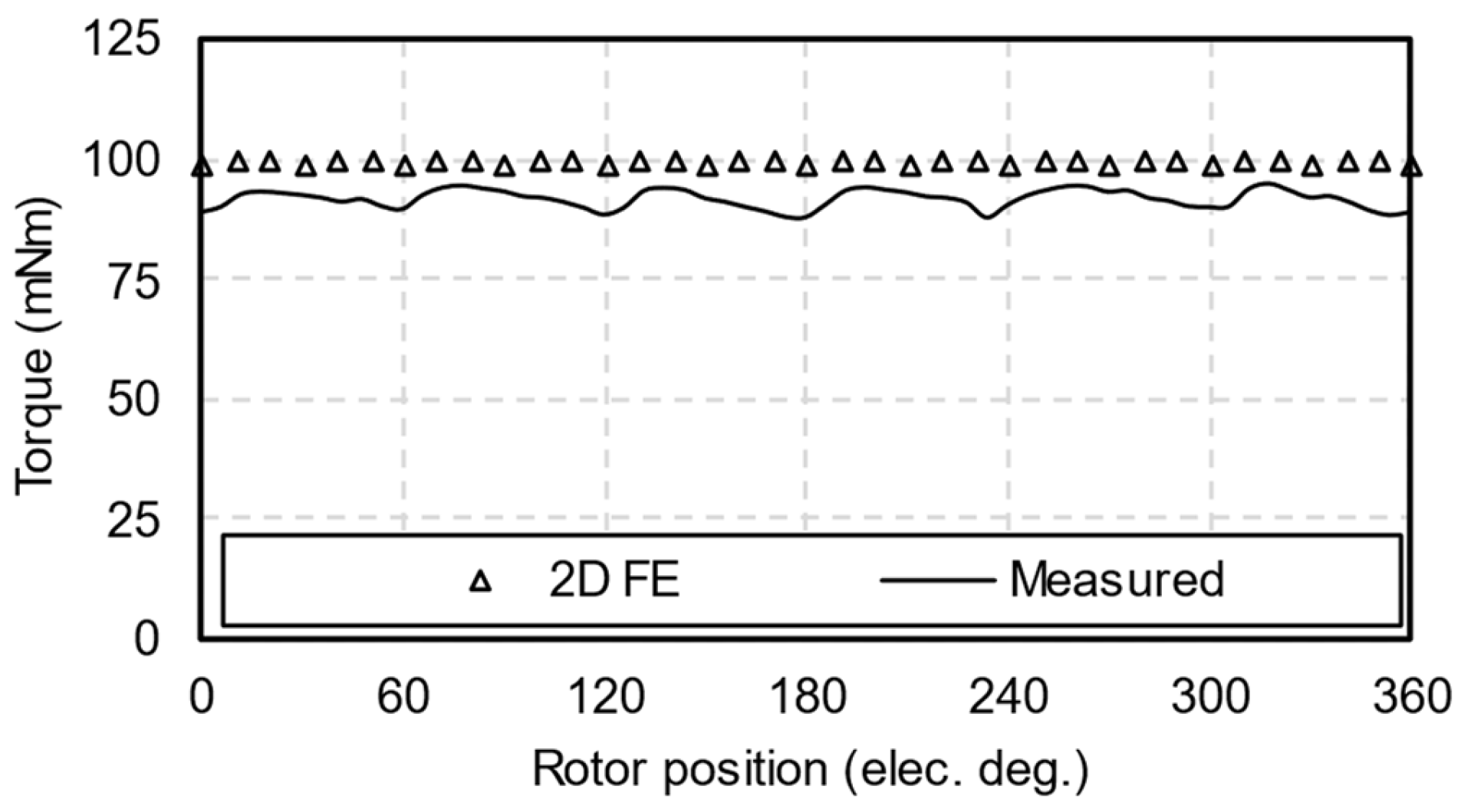
5. Experimental Validation

An HCM with the proposed sinusoidal-shaped inner rotor was manufactured. The inner rotor core thickness function was injected with the sixth harmonic. Photos of the prototype machine are shown in Figure 19. During the measurement of phase back-EMFs, the prototype machine was open-circuited and a servo motor was employed to drive the rotor of the prototype machine. The measured data was obtained by an oscilloscope. On the other hand, a static test rig introduced in [25] was used to measure the rated torque of the prototype machine. Figure 20 shows a photo of the static test rig. The rotor position of the prototype machine is locked by a balanced beam and weight. The stator position of the prototype machine can be manually adjusted and locked by an indexing table. A DC power supply powers the winding on the prototype machine. During the measurement, the stator position was adjusted step by step. The injected DC current was also adjusted step by step. The relationship between stator position and injected current is consistent with the Id = 0 control strategy. The prototype machine’s output torque will act on the weight through the balanced beam. When the prototype machine outputs torque, the digital gauge reading will vary. Therefore, output torque can be measured by reading the digital gauge.
A screenshot of measured phase back-EMFs is shown in Figure 21. Figure 22 compares the 2D FE-predicted and measured phase back-EMFs. The 2D FE-predicted and measured back-EMFs have similar waveforms, while the fundamental component of the measured results is 7% lower than the 2D FE prediction, mainly caused by end leakage. Since the HCM has a large air-gap length but a short axial length, it suffers from the perceptible end effect. Furthermore, the amplitudes of measured fifth and seventh back-EMF harmonics are unequal, and the three-phase back-EMFs are slightly unbalanced, possibly caused by imperfect manufacturing.
Figure 23 compares the measured and 2D FE-predicted rated torques. The measured average torque is 7% lower than its predicted counterpart, consistent with the analysis of measured back EMFs. Due to phase back-EMF distortions, the measured torque ripple was 7%. However, it should be noted that, although the prototype machine exhibited a higher torque ripple than the 2D FE-predicted result, its torque ripple is still much lower than conventional HCMs. Overall, the aforementioned analyses can be validated through experiments.

6. Conclusions

In this paper, a novel inner rotor with a sinusoidal shape is proposed to reduce torque ripple in HCMs. By injecting harmonics into the thickness function of the inner rotor, air-gap flux density harmonics and back-EMF can be adjusted. Under certain phases of injected harmonics and Id = 0 control strategy, torque ripples caused by the fifth and seventh back-EMF harmonics can be eliminated. Hence, the torque ripple reaches its minimum value when the amplitudes of the fifth and seventh back-EMF harmonics are equal. As opposed to other injected harmonics, injecting the sixth harmonic will suppress the fifth back-EMF harmonic and enhance the seventh back-EMF harmonic simultaneously. Therefore, it can achieve the lowest torque ripple with a smaller amplitude of injected harmonic. Moreover, the smaller amplitude of the injected harmonic also means a smaller equivalent air-gap length and thus, higher average torque. Although some conventional methods can suppress HCM torque ripples, they suffer from relatively low average torques. The performance of the proposed HCM can be further improved by adding a short-circuited damper winding on the inner rotor surface, which will be investigated in the future.

Author Contributions

Conceptualization, L.Z.; methodology, L.Z. and Z.C.; validation, P.S. and L.W.; formal analysis, L.Z.; investigation, L.Z. and Z.C.; resources, X.L.; data curation, L.Z. and P.S.; writing—original draft preparation, L.Z. and Z.C.; writing—review and editing, P.S. and X.L.; visualization, L.W.; supervision, X.L.; project administration, X.L.; funding acquisition, X.L. All authors have read and agreed to the published version of the manuscript.

Funding

This research was funded by the Zhejiang Province Basic Public Welfare Research Program, grant number LGF22E070003.

Data Availability Statement

Data are contained within the article.

Conflicts of Interest

The authors declare no conflicts of interest.

References

  1. Peng, C.; Fang, J.C.; Cui, P.L. Dynamics modeling and measurement of the microvibrations for a magnetically suspended flywheel. IEEE Trans. Instrum. Meas. 2015, 64, 3239–3252. [Google Scholar] [CrossRef]
  2. Liu, Q.; Wang, K.; Ren, Y.; Chen, X.C.; Ma, L.M.; Zhao, Y. Optimization design of launch locking protective device (LLPD) based on carbon fiber bracket for magnetically suspended flywheel (MSFW). Acta Astronaut. 2019, 154, 9–17. [Google Scholar]
  3. Tang, D.Y.; Gong, M.T.; Tian, L.M.; Yu, J.S.; Zhang, J.Y.; Zhang, Q. Health indicator construction of high-speed rotating bearings in aerospace CMG based on physics-inspired machine-learning approach. IEEE Trans. Instrum. Meas. 2022, 71, 3524411. [Google Scholar] [CrossRef]
  4. Sun, J.J.; Xing, G.; Zhou, X.X.; Sun, H.X. Static magnetic field analysis of hollow-cup motor model and bow-shaped permanent magnet design. Chin. J. Aeronaut. 2022, 35, 306–313. [Google Scholar] [CrossRef]
  5. Sun, J.J.; Ren, J.Y.; Sun, H.X. A novel design of an inner rotor for optimizing the air-gap magnetic field of hollow-cup motors. Machines 2022, 10, 314. [Google Scholar] [CrossRef]
  6. Zhu, X.F.; Hua, W.; Wu, Z.Z.; Huang, W.T.; Zhang, H.L.; Cheng, M. Analytical approach for cogging torque reduction in flux-switching permanent magnet machines based on magnetomotive force-permeance model. IEEE Trans. Ind. Electron. 2018, 65, 1965–1979. [Google Scholar] [CrossRef]
  7. Gao, Y.T.; Qu, R.H.; Li, D.W.; Li, J. Torque performance analysis of three-phase flux reversal machines. IEEE Trans. Ind. Appl. 2017, 53, 2110–2119. [Google Scholar] [CrossRef]
  8. Zhang, L.; Wu, L.J.; Wen, H.; Niu, F.; Lu, Q.F. Improved primary/secondary pole number combinations for dual-armature linear switched flux permanent magnet machines. IEEE Trans. Transport. Electrif. 2021, 7, 2589–2599. [Google Scholar] [CrossRef]
  9. Qi, J.; Zhu, Z.Q.; Yan, L.C.; Jewell, G.W.; Gan, C.W.; Ren, Y.; Brockway, S.; Hilton, C. Suppression of torque ripple for consequent pole PM machine by asymmetric pole shaping method. IEEE Trans. Ind. Appl. 2022, 58, 3545–3557. [Google Scholar] [CrossRef]
  10. Zhang, X.T.; Zhang, C.M.; Yu, J.K.; Du, P.C.; Li, L.Y. Analytical model of magnetic field of a permanent magnet synchronous motor with a trapezoidal Halbach permanent magnet array. IEEE Trans. Magn. 2019, 55, 8105205. [Google Scholar] [CrossRef]
  11. Zhang, L.F.; Wang, K.; Sun, H.Y.; Zhu, S.S. Multiphase PM machines with Halbach array considering third harmonic flux density. IEEE Trans. Ind. Electron. 2019, 66, 9184–9193. [Google Scholar] [CrossRef]
  12. Liu, K.; Yin, M.; Hua, W.; Ma, Z.Q.; Lin, M.Y.; Kong, Y. Design and analysis of Halbach ironless flywheel BLDC motor/generators. IEEE Trans. Magn. 2018, 54, 8109305. [Google Scholar] [CrossRef]
  13. Wang, Z.Y.; Yang, J.T.; Dai, S.R.; Feng, Y.J.; Huang, S.D. Novel dual-rotor single-stator coreless permanent magnet machine with dual-flywheel. IEEE Trans. Magn. 2022, 58, 8106506. [Google Scholar] [CrossRef]
  14. Xia, C.L.; Guo, L.Y.; Wang, H.M. Modeling and analyzing of magnetic field of segmented Halbach array permanent magnet machine considering gap between segments. IEEE Trans. Magn. 2014, 50, 8106009. [Google Scholar] [CrossRef]
  15. Li, Y.; Xing, J.W.; Wang, T.B.; Lu, Y.P. Programmable design of magnet shape for permanent-magnet synchronous motors with sinusoidal back EMF waveforms. IEEE Trans. Magn. 2008, 44, 2163–2167. [Google Scholar]
  16. Zhou, Y.; Li, H.S.; Meng, G.W.; Zhou, S.; Cao, Q. Analytical calculation of magnetic field and cogging torque in surface-mounted permanent-magnet machines accounting for any eccentric rotor shape. IEEE Trans. Ind. Electron. 2015, 62, 3438–3447. [Google Scholar] [CrossRef]
  17. Chen, Z.F.; Xia, C.L.; Geng, Q.; Yan, Y. Modeling and analyzing of surface-mounted permanent-magnet synchronous machines with optimized magnetic pole shape. IEEE Trans. Magn. 2014, 50, 8102804. [Google Scholar] [CrossRef]
  18. Zeng, Y.; Cheng, M.; Liu, G.H.; Zhao, W.X. Effects of magnet shape on torque capability of surface-mounted permanent magnet machine for servo applications. IEEE Trans. Ind. Electron. 2020, 67, 2977–2990. [Google Scholar] [CrossRef]
  19. Du, Z.S.; Lipo, T.A. High torque density and low torque ripple shaped-magnet machines using sinusoidal plus third harmonic shaped magnets. IEEE Trans. Ind. Appl. 2019, 55, 2601–2610. [Google Scholar] [CrossRef]
  20. Park, J.C.; Kim, J.H.; Park, S.H.; Kim, K.O.; Sung, M.H.; Lim, M.S. Design optimization using asymmetric rotor in IPMSM for torque ripple reduction considering forward and reverse directions. IEEE Trans. Magn. 2023, 59, 8205805. [Google Scholar] [CrossRef]
  21. Shimizu, Y.; Morimoto, S.; Sanada, M.; Inoue, Y. Investigation of rotor topologies for reducing torque ripple in double-layer IPMSMs for automotive applications. IEEE Trans. Ind. Electron. 2023, 70, 8276–8285. [Google Scholar] [CrossRef]
  22. Xu, Y.M.; Xu, Z.Y.; Cao, H.P.; Liu, W.H. Torque ripple suppression of synchronous reluctance motors for electric vehicles based on rotor improvement design. IEEE Trans. Transport. Electrific. 2023, 9, 4328–4338. [Google Scholar] [CrossRef]
  23. Mohammadi, S.E.M.; Chen, P.Y.; Moallem, M.; Fahimi, B.; Kiani, M. An alternate rotor geometry for switched reluctance machine with reduced torque ripple. IEEE Trans. Energy Convers. 2023, 38, 939–947. [Google Scholar] [CrossRef]
  24. Wu, Z.Z.; Zhu, Z.Q. Analysis of air-gap field modulation and magnetic gearing effects in switched flux permanent magnet machines. IEEE Trans. Magn. 2015, 51, 8105012. [Google Scholar] [CrossRef]
  25. Zhu, Z.Q. A simple method for measuring cogging torque in permanent magnet machines. In Proceedings of the 2009 IEEE Power & Energy Society General Meeting, Calgary, AB, Canada, 26–30 July 2009. [Google Scholar]
Figure 1. Topology of a conventional HCM.
Energies 17 03168 g001
Figure 2. Air gap MMF generated by tile-shaped PMs.
Energies 17 03168 g002
Figure 3. Air-gap permeance.
Energies 17 03168 g003
Figure 4. Topology of HCM with proposed sinusoidal-shaped inner rotor.
Energies 17 03168 g004
Figure 5. Phases of back-EMF harmonics versus phases of second, fourth, sixth, and eighth injected harmonics. (a) Fifth back-EMF harmonic; (b) seventh back-EMF harmonic.
Energies 17 03168 g005
Figure 6. Amplitudes of back-EMF harmonics versus phases of second, fourth, sixth, and eighth injected harmonics. (a) Fifth back-EMF harmonic; (b) seventh back-EMF harmonic.
Energies 17 03168 g006
Figure 7. Torque performance versus second, fourth, sixth, and eighth injected harmonic phases. (a) Average torque; (b) torque ripple.
Energies 17 03168 g007
Figure 8. Amplitudes of the fifth and seventh back-EMF harmonics versus amplitudes of injected harmonics. (a) Second injected harmonic; (b) fourth injected harmonic; (c) sixth injected harmonic; (d) eighth injected harmonic.
Energies 17 03168 g008
Figure 9. Torque performances versus amplitudes of second, fourth, sixth, and eighth injected harmonics. (a) Average torque; (b) torque ripple.
Energies 17 03168 g009
Figure 10. Torque performance of the sixth harmonic injection. (a) Average torque; (b) torque ripple.
Energies 17 03168 g010
Figure 11. Open-circuit radial air-gap flux densities. (a) Waveforms; (b) spectra.
Energies 17 03168 g011
Figure 12. Open-circuit inductances. (a) D-axis inductances; (b) Q-axis inductances.
Energies 17 03168 g012
Figure 13. Phase back-EMFs. (a) Waveforms; (b) spectra.
Energies 17 03168 g013
Figure 14. On-load phase voltages. (a) Waveforms; (b) spectra.
Energies 17 03168 g014
Figure 15. Rated torques. (a) Waveforms; (b) spectra.
Energies 17 03168 g015
Figure 16. Illustration of conventional PM-shaping methods. (a) Bow-shaped PM; (b) PM with harmonic injection.
Energies 17 03168 g016
Figure 17. Rated torque comparison between proposed sinusoidal-shaped inner rotor and conventional PM-shaping methods.
Energies 17 03168 g017
Figure 18. Rated torque waveforms of HCMs with conventional methods of torque ripple reduction.
Energies 17 03168 g018
Figure 19. Photos of the prototype machine. (a) Laminations; (b) rotors; (c) stator.
Energies 17 03168 g019
Figure 20. Static test rig for rated torque measurement.
Energies 17 03168 g020
Figure 21. Screenshot of measured phase back-EMFs below 2000 rpm.
Energies 17 03168 g021
Figure 22. Comparison between 2D FE-predicted and measured phase back-EMFs below 2000 rpm. (a) Waveforms; (b) spectra.
Energies 17 03168 g022
Figure 23. Comparison between 2D FE predicted and measured rated torques.
Energies 17 03168 g023
Table 1. Harmonic order of air-gap flux density produced by PM-generated air-gap MMF and air-gap permeance harmonics.
Harmonic Order of
Air-Gap MMF
1357
Harmonic Order
of Air-Gap Permeance
01357
10, 22, 44, 66, 8
21, 31, 53, 75, 9
32, 40, 62, 84, 10
43, 51, 71, 93, 11
54, 62, 80, 102, 12
65, 73, 91, 111, 13
76, 84, 102, 120, 14
87, 95, 113, 131, 15
Table 2. Basic parameters of HCMs.
ParameterUnitValue
Number of poles-12
Number of slots-9
Rated speedrpm10,000
Rated phase currentArms3.1
Active axial lengthmm6
Outer radius of outer rotormm81
Thickness of outer rotor coremm6
Thickness of PMmm2.5
Pole-arc to pole-pitch ratio of PM-1
Maximum thickness of inner rotor coremm4.2
Table 3. Optimized parameters of injected harmonics.
ItemUnitInjected Harmonic Order
2nd4th6th8th
Amplitudemm0.61.20.61.2
Phase°1801800180
Table 4. Rated torque performances of HCMs.
ItemUnitInjected Harmonic Order
None2nd4th6th8th
Average torquemNm107101869988
Peak-to-peak torquemNm13.111.54.11.65.8
Torque ripple%12.211.44.81.66.6
Table 5. Rated torque characteristics of HCMs with different methods of torque ripple reduction.
MethodAverage Torque (mNm)Peak-to-Peak Torque (mNm)Torque Ripple (%)
IR-6991.61.6
PM-B943.63.8
PM-5961.31.4
PM-7951.41.5
SS971.51.5
SP972.22.3
PMW973.53.6
IG9611.411.9
Disclaimer/Publisher’s Note: The statements, opinions and data contained in all publications are solely those of the individual author(s) and contributor(s) and not of MDPI and/or the editor(s). MDPI and/or the editor(s) disclaim responsibility for any injury to people or property resulting from any ideas, methods, instructions or products referred to in the content.

