Article

Experimental Study on the Performance of an Air Conditioning Unit with a Baffled Indirect Evaporative Cooler

1
Graduate School of Refrigeration and Air-Conditioning Engineering, Pukyong National University, Busan 48513, Republic of Korea
2
Department of Refrigeration and Air-Conditioning Engineering, Chonnam National University, Yeosu 59626, Republic of Korea
3
Department of Refrigeration and Air-Conditioning Engineering, Pukyong National University, Busan 48513, Republic of Korea
*
Author to whom correspondence should be addressed.
Energies 2024, 17(13), 3231; https://doi.org/10.3390/en17133231
Submission received: 13 May 2024 / Revised: 26 June 2024 / Accepted: 28 June 2024 / Published: 1 July 2024
(This article belongs to the Special Issue Thermo-Fluids and Heat Transfer Engineering)

Abstract

:
Indirect evaporative coolers (IECs) use the latent heat of water evaporation to cool air. This system has the advantage of operating at low power without a compressor and does not increase the absolute humidity of the air. However, an IEC is difficult to use on its own because its cooling capacity is limited by the theoretical constraint of the wet-bulb temperature of the ambient air. Therefore, an air conditioning unit (ACU) was integrated with an IEC and experimentally evaluated in this study. The dry and wet channels of the IEC were integrated with an ACU evaporator and a condenser, unlike previous studies where IECs were integrated solely with either an evaporator or a condenser. This reduced the cooling load on the evaporator and helped the condenser to dissipate heat to improve the performance of the existing ACU. In addition, the IEC was equipped with baffles to improve its performance. To assess the extent of the performance improvement due to integration with the IEC, comparisons were also performed under the same experimental conditions with an ACU only. The results showed that under conditions with an indoor temperature of 32 °C, integrating the IEC with the ACU increased the average cooling capacity by 13.1% and decreased the average power consumption by 8.60% during the test period, compared to using only the ACU. Consequently, the average coefficient of performance (COP) increased by 19.5% compared to using only the ACU under the same conditions.

1. Introduction

Approximately 40% of the world’s energy is consumed by buildings and a significant portion of this energy is used for cooling [1,2]. Additionally, a substantial portion of the building energy consumption is allocated to the cooling of residential buildings, although commercial buildings such as factories and data centers consume significant amounts [3]. Therefore, considerable research has been conducted on low-power cooling systems that can replace the previously used electric compressor-driven air conditioning units (ACUs). Among these, research is being conducted on evaporative coolers, which do not require electrical compressors or other heat sources.
Pescod [4] performed an early study on the characteristics of indirect evaporative coolers (IEC). An IEC utilizes the latent heat released during water evaporation to exchange heat indirectly with air. This offers the advantage of being easy to maintain and does not increase the absolute humidity of the cooled air, unlike other evaporative coolers. Several studies have evaluated the performance of IECs.
Cui et al. [5] evaluated the performance of an IEC using the log-mean temperature difference (LMTD) method. They assessed the performance by varying the air temperature, humidity, air velocity, channel length, and height. Pandelidis et al. [6] compared the performance of four types of IECs based on variations in the airflow configurations. The four types included a conventional counterflow exchanger, a regenerative exchanger, a perforated regenerative exchanger, and a new type of counterflow exchanger equipped with dampers. They found that, among the four types, the counterflow exchanger exhibited the highest performance. Kabeel and Abdelgaied [7] evaluated the performance of a novel IEC by attaching baffles to the dry channel. Their research confirmed that the installation of baffles enhanced the cooling performance and efficiency of the IEC. Chen et al. [8,9] conducted parameter analysis and optimization considering condensation in the primary channel of the IEC. They evaluated the total energy savings and number of transfer units (NTU) by varying the temperature, humidity, and velocity of the inlet air, as well as the channel gap of the air channel. Min et al. [10,11] modeled a cross-flow IEC in two dimensions to evaluate its performance. Based on the validated model, they compared the cross-flow and counter-flow cases by varying the operational parameters, such as the air temperature, humidity, and velocity. Furthermore, they investigated the optimized design values by altering the geometric parameters of the IEC, such as the channel gap, number of transfer units, and height-to-length ratio. Comprehensive reviews focused on improving the performance of IECs can be found in Refs. [12,13,14,15,16].
The cooling capacity of an IEC is limited by the theoretical constraint of the wet-bulb temperature of the ambient air [17]. Since the wet-bulb temperature represents the lowest temperature that the air can reach using only evaporation, the temperature of the air cannot be lowered beyond this point once it has reached the wet bulb. This limitation significantly restricts the potential cooling capacity of the air. Therefore, it is difficult to independently use an IEC to handle indoor cooling loads. To solve these problems, a system that combines an existing compressed air cooling system with an IEC is proposed. Another study integrated an IEC into an air handling unit (AHU) or ventilator, which are commonly used in medium-to-large buildings [18,19]. Additionally, systems that connect the condenser of a conventional ACU to a direct evaporative cooler (DEC), similar to an IEC that utilizes evaporative latent heat, have also been investigated [20,21]. Recently, Yan et al. [22,23] integrated an IEC with the evaporation of an ACU and numerically assessed its performance. As a result, integrating the IEC with the evaporation of the ACU was found to save between 22.1 and 34.1% of energy compared to using the ACU alone.
Table 1 summarizes previous studies that have integrated IECs with different cooling systems. The integration strategies remain underdeveloped and reveal several research gaps. The reviewed studies involving IEC integration typically focus on connecting them with AHUs or ventilators, used in medium to large buildings, or with ACUs targeted at small buildings that are linked to DECs. There is limited research on the connection between IECs and ACUs used in rooms or mall buildings, which also have the limitation of only connecting the outside air to the evaporator of the ACU after primary cooling. This limitation served as the motivation for this study.
Therefore, this study proposes a system that integrates both the evaporator and condenser of an ACU with an IEC and experimentally evaluates its performance. Cooled air from the dry channel is sent to the evaporator, whereas the air cooled in the wet channel is directed to the condenser. This reduces the cooling load on the existing evaporator and enhances the heat dissipation from the condenser, thereby improving the performance of the ACU when integrated. Additionally, baffles were attached to the dry channel to enhance the IEC performance [7]. The performance of the proposed ACU with the IEC was evaluated through experiments conducted in a chamber with a constant temperature and humidity. Furthermore, to evaluate the performance enhancement resulting from integrating the IEC into the ACU, we compared it with existing commercial ACUs under the same experimental conditions.

2. Experimental Apparatus and Method

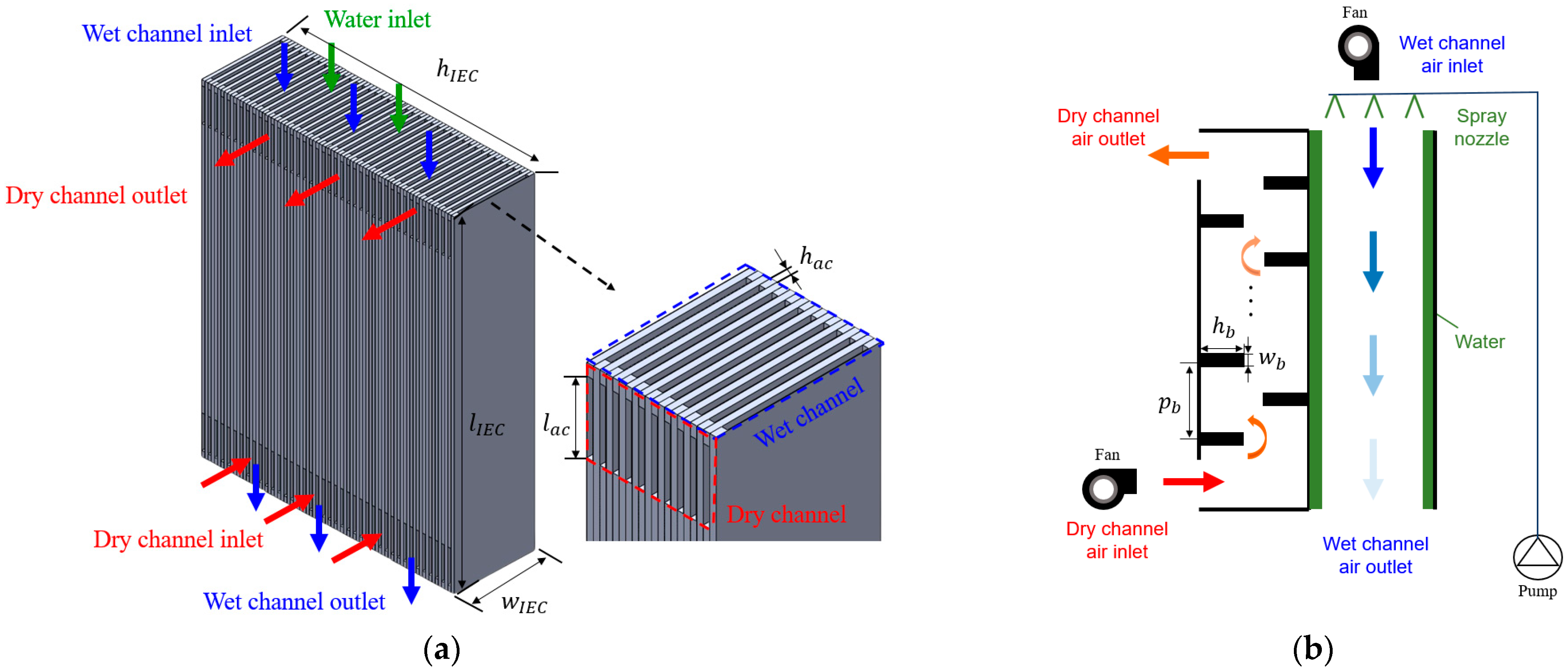
2.1. Description of Baffled IEC

Figure 1 shows a schematic diagram of the baffled IEC fabricated in this study. An IEC consists of a dry channel, in which water and air do not come into contact, and a wet channel, in which contact with water leads to evaporation. The air in the dry channel and wet channel exchanged heat in the counter-flow, and water was sprayed downward using a spray nozzle. In the dry channel of the IEC, baffles are installed on the plates to increase the heat transfer area and promote turbulence to enhance the heat transfer performance. We also attached insulation to all of the parts, excluding those in which air and water flowed.
The dry and wet channels used 0.5-mm-thick aluminum plates. The height of the air channels ( h a c ) between the plates was 5 mm and the length of the air channel inlet ( l a c ) was 90 mm. The length ( l I E C ) , width ( w I E C ) , and height ( h I E C ) of the IEC were 900, 210, and 600 mm, respectively [14]. It consisted of 55 dry channels and 55 wet channels. The height ( h b ), width ( w b ), and pitch ( p b ) of the baffles were 2, 5, and 116 mm, respectively, with 11 attached to each channel [7]. Insulation with a thickness of 5 mm was attached to all parts, except for the air and water inlets and outlets, to prevent heat loss to the surroundings. The geometrical characteristics of the baffle and IEC are summarized in Table 2.

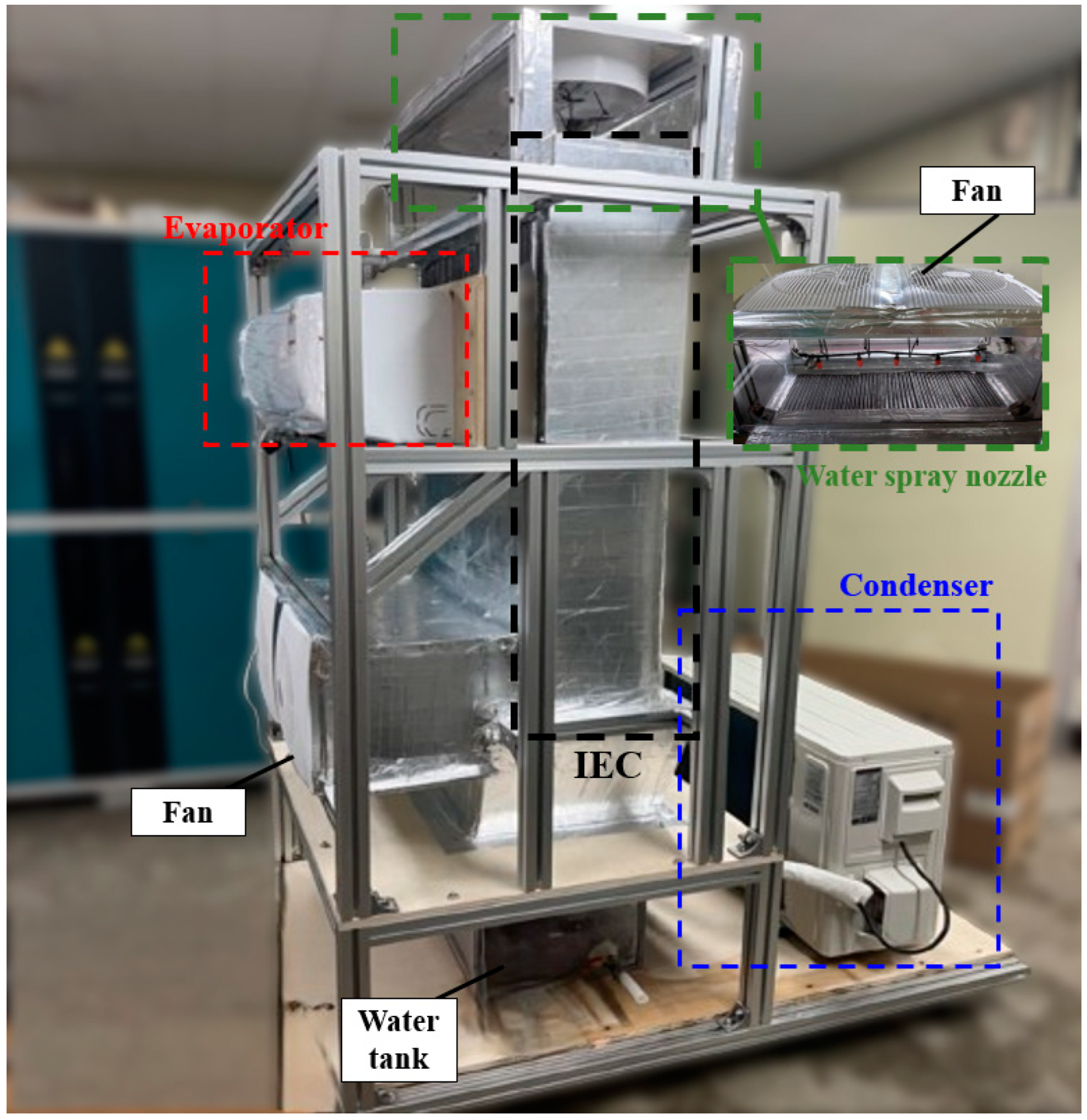
2.2. Description of ACU with Baffled IEC

Figure 2 shows a schematic of the proposed ACU with a baffled IEC. Air enters the dry channel of the IEC and is cooled within the IEC. The primarily cooled air then passes through the ACU evaporator and is supplied indoors. In addition, the air entering the wet channel undergoes heat exchange within the IEC, resulting in air that is more humid and cooler than the ambient air. The cooled air from the wet channel is then sent to the external condenser of the ACU. Consequently, this reduces the indoor load handled by the evaporator and enhances the heat dissipation from the condenser. In our experiment, we used indoor air on the wet air side for indirect heat exchange. Given the hot and humid summer conditions of our region, using fresh outdoor air would be less effective for evaporation and could increase the dry channel air outlet temperature. Therefore, we determined that using indoor air on the wet air side would be more effective in such climates and conducted our experiment accordingly.
The ACU is composed of both a condenser unit (Samsung Electronics Co., Ltd., AR06A1170HAX, Suwon-si, Republic of Korea) and an evaporator unit (Samsung Electronics Co., Ltd., AR06A117HZN, Suwon-si, Republic of Korea). The condenser and evaporator have a rated capacity of 2.30 kW and rated power consumption of 0.73 kW. The refrigeration system used the R410A refrigerant. The compressor used in this ACU (Rechi Precision Co., Ltd., 39A23MY, Taiwan) is a 910 W scroll compressor.
Figure 3 shows an actual view of the proposed ACU with a baffled IEC. Centered on the IEC, a fan that supplies air to the wet channel and a spray nozzle that sprays water are installed on the top, and a water tank that can store fallen water is installed at the bottom. The inlet and outlet of the dry channel are located at the front of the IEC. The indoor air is drawn into the IEC through the inlet of the dry channel. The cooled air from the IEC exits through the upper outlet of the dry channel and enters the evaporator inlet. The rear of the IEC is equipped with a duct that allows the movement of moist cooled air from the wet channel to the inlet of the condenser. Blowers are installed to supply air to the entrance of each channel and a nozzle spray is installed at the top of the IEC to spray water. A water pump is installed to draw water from the water tank to the top of the IEC.

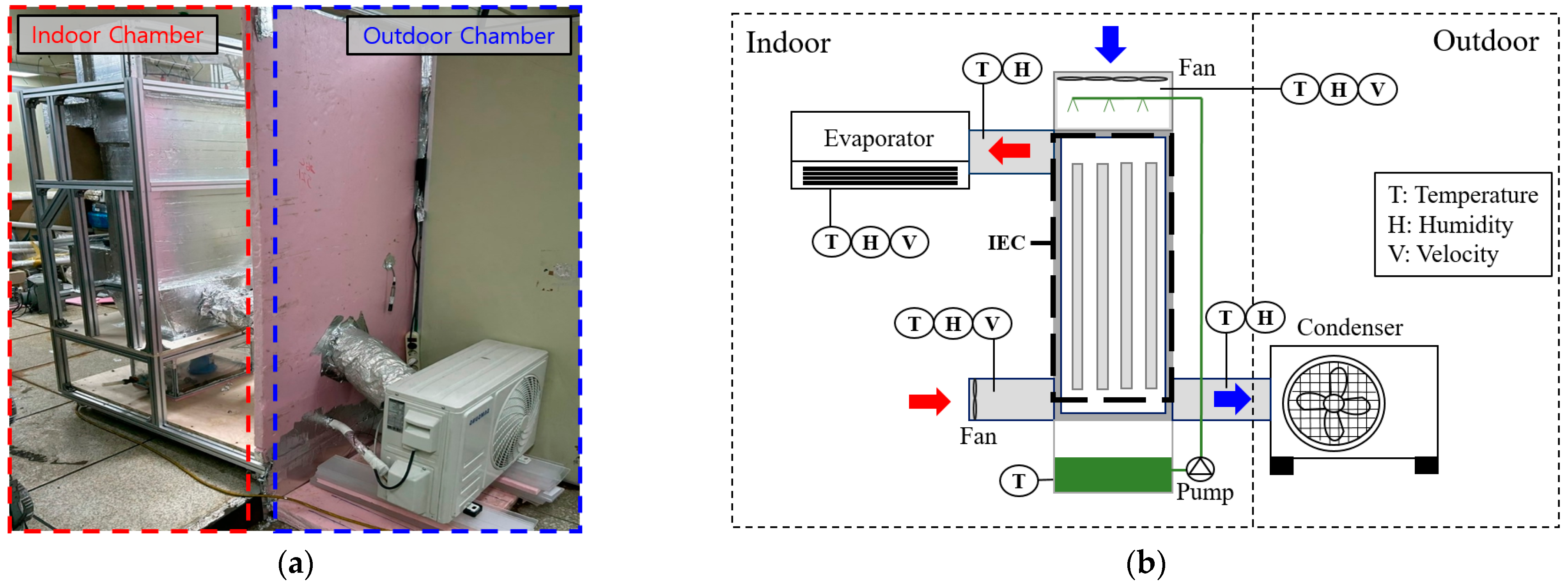
2.3. Experimental Setup

Figure 4 illustrates the actual experimental environment and measurement location of the ACU with a baffled IEC. The experiments were conducted in a chamber. The temperature of the chamber was set at 27 °C, 32 °C, and 36 °C, respectively, and the relative humidity was fixed at 47 ± 2%. The air velocity in each IEC channel was fixed at 2 m/s. In addition, the degree of performance improvement when integrating a baffled IEC with an existing ACU was evaluated. Therefore, two sets of experiments were repeated under identical conditions. One experiment involved operating the ACU alone, whereas the other consisted of operating the ACU coupled with a baffled IEC.
In this experiment, temperature and humidity sensors were used to measure the air temperature and humidity, while an anemometer was used to measure the air velocity. A power meter was used to measure the power consumption of the ACU along with the fans and pumps required to operate the IEC. The specifications of the measurement devices are presented in Table 3.

2.4. Performance Indices

To evaluate the performance of the ACU with a baffled IEC, key factors such as the cooling capacity and coefficient of performance (COP) were assessed [18]. The Q I E C and Q A C U are calculated as follows:
Q I E C = m a ˙ c p , a ( T d , i n T d , o u t ) ,
Q A C U = m a ˙ c p , a ( T e v a , i n T e v a , o u t ) ,
where m a ˙ is the mass flow rate of air and T d , i n and T d , o u t are the inlet and outlet air temperatures of the dry channel, respectively. In addition, T e v a , i n and T e v a , o u t are the inlet and outlet air temperatures of the evaporator, respectively. The power consumption of the ACU with the IEC can be expressed as follows:
W t o t a l = W A C U + W f a n + W p u m p ,
where W A C U is the total power consumption of the ACU, including the fan and compressor, and W f a n and W p u m p are the power consumption of the fan and pump used in the IEC, respectively. The C O P I E C , C O P A C U , and C O P t o t a l can be calculated as follows:
C O P I E C = Q I E C W I E C
C O P A C U = Q A C U W A C U
C O P t o t a l = Q A C U + Q I E C W t o t a l

2.5. Uncertainty Analysis

There may be errors in the experimental data related to the ACU with an IEC. This is because a sensor, which measures various elements, introduces uncertainties. Thus, to accurately evaluate the primary performance of an ACU with an IEC, it is necessary to assess the error associated with each performance value [27]. The uncertainty of the parameter is obtained as follows:
y = f ( x 1 ,   x 2 ,   ,   x n )
δ y = ( δ y δ x 1 δ x 1 ) 2 + ( δ y δ x 2 δ x 2 ) 2 + + ( δ y δ x n δ x n ) 2
where δ x 1 ,   δ x 2 , , δ x n are the uncertainties of the directly measured values. The main performance parameters of the ACU with the IEC evaluated in this study included Q I E C ,   Q A C U ,   W t o t a l , C O P I E C , C O P A C U , and C O P t o t a l . The parameters and their uncertainties are listed in Table 4. To derive the relative uncertainties presented in Table 4, the absolute uncertainties calculated using Equation (8) were divided by the corresponding measured values.

3. Results and Discussion

3.1. Performance of IEC

Figure 5 shows the performance of the IEC at various indoor air temperatures. The air temperature differences in the dry channel range from 1.08 °C to 1.79 °C, 2.90 °C to 3.52 °C, and 4.68 °C to 5.78 °C for indoor temperatures of 27 °C, 32 °C, and 36 °C, respectively, with average air temperature differences of 1.44 °C, 3.27 °C, and 5.50 °C. The average air temperature differences increased by 4.06 °C and 2.23 °C when the indoor temperature was at 36 °C, compared to indoor temperatures of 27 °C and 32 °C, respectively.
Additionally, the cooling capacity of the IEC ranges from 136 W to 225 W, 341 W to 415 W, and 552 W to 681 W for indoor temperatures of 27 °C, 32 °C, and 36 °C, respectively, with average values of 181 W, 385 W, and 648 W. The cooling capacity increased by 2.58 times and 0.68 times when the indoor temperature was at 36 °C, compared to indoor temperatures of 27 °C and 32 °C, respectively.
The COP of the IEC ranges from 1.10 to 1.83, 2.77 to 3.36, and 4.47 to 5.52 for indoor temperatures of 27 °C, 32 °C, and 36 °C, respectively, with average values of 1.46, 3.12, and 5.25. The COP at 36 °C increased by an average of 2.59 and 1.13 times compared with at 27 °C and 30 °C, respectively. The IEC performance showed an increasing trend as the indoor temperature increased. This is because the difference between the wet bulb and temperatures tended to increase as the indoor temperature increased.

3.2. Performance of IEC with AC

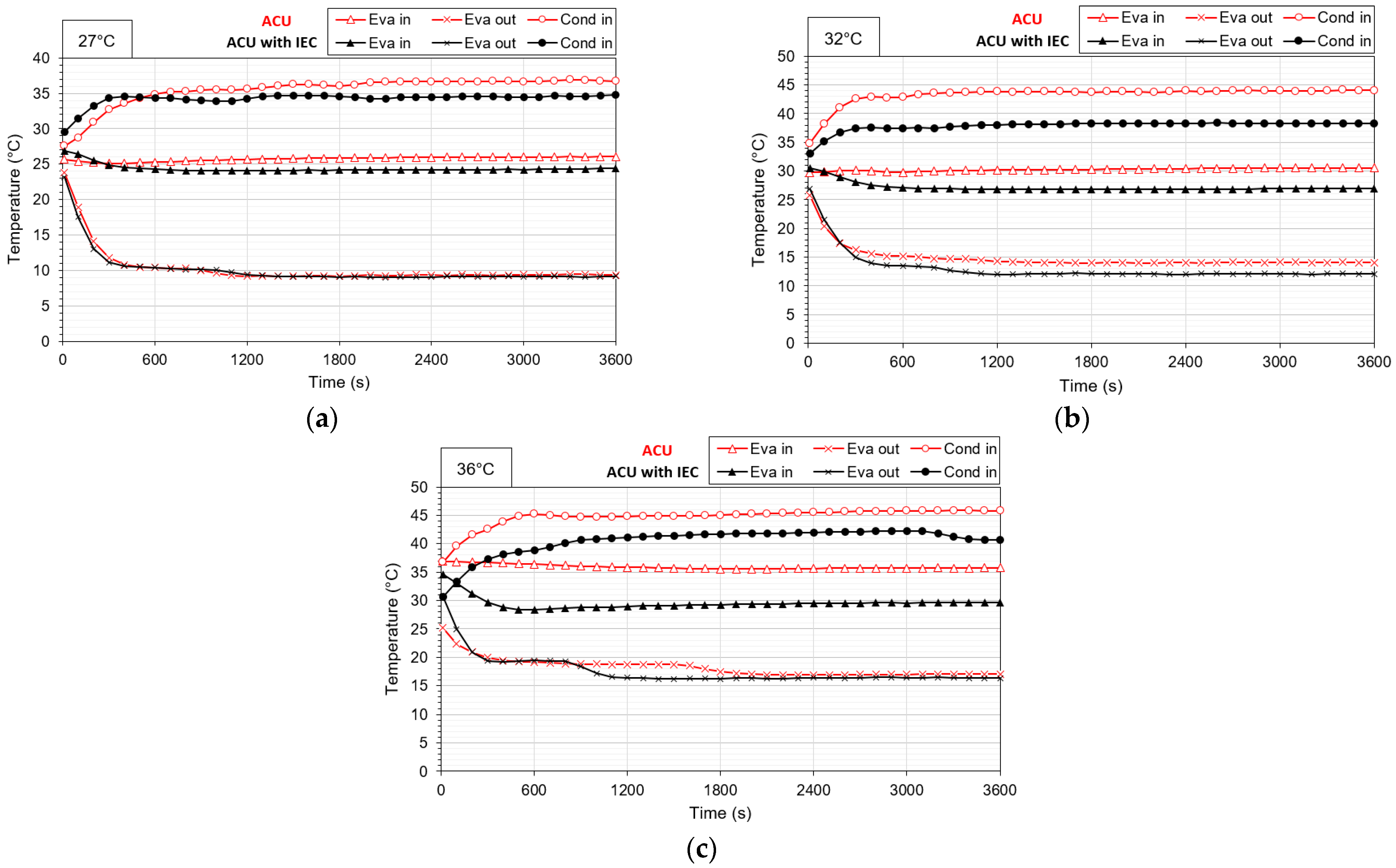
3.2.1. Temperature Difference

Figure 6 shows the temperatures of the air entering the condenser and evaporator of the ACU during the test period at various indoor temperatures. In all cases, when the ACU was integrated with the IEC, the evaporator inlet, outlet, and condenser inlet temperatures were lower than those when the ACU was operated alone.
The average inlet air temperature of the evaporator for the ACU with the IEC was 24.4 °C, 27.2 °C, and 29.6 °C at indoor temperatures of 27 °C, 32 °C, and 36 °C, respectively, compared to 25.8 °C, 30.3 °C, and 35.9 °C when operating the ACU alone. The average inlet air temperature of the evaporator for the ACU with the IEC decreased by 1.35 °C, 3.01 °C, and 6.37 °C, respectively, compared to operating the ACU alone at these indoor temperatures. This decrease was due to air cooling in the IEC’s dry channel entering the ACU’s evaporator, and it was observed that the reduction was greater at higher temperatures.
The average outlet air temperature of the evaporator for the ACU with the IEC was 10.1 °C, 13.2 °C, and 17.7 °C at indoor temperatures of 27 °C, 32 °C, and 36 °C, respectively, compared to 10.3 °C, 14.9 °C, and 18.2 °C when operating the ACU alone. The average inlet air temperature of the evaporator for the ACU with the IEC showed a slight decrease compared with that when the ACU was operated alone.
The average inlet air temperature of the condenser for the ACU with the IEC was 34.2 °C, 37.8 °C, and 40.4 °C at indoor temperatures of 27 °C, 32 °C, and 36 °C, respectively, compared to 35.5 °C, 43.3 °C, and 44.7 °C when operating the ACU alone. The average inlet air temperature of the condenser for the ACU with the IEC decreased by 1.26 °C, 5.42 °C, and 4.26 °C, respectively, at these temperatures. This reduction occurred because the cooled air in the wet IEC channel entered the ACU condenser inlet.

3.2.2. Cooling Capacity

Figure 7 shows the cooling capacity of the ACU with the IEC at various indoor air temperatures. When operating the ACU alone, the cooling capacity was 1756 W, 1705 W, and 1821 W at indoor temperatures of 27 °C, 32 °C, and 36 °C, respectively. The ACU with IEC showed cooling capacities of 1276 W, 1543 W, and 1583 W, whereas the IEC contributed 181 W, 385 W, and 648 W, resulting in total capacities of 1763 W, 1928 W, and 1924 W, respectively. The total cooling capacity of the ACU with the IEC increased by 0.4%, 13.1%, and 5.7% at 27 °C, 32 °C, and 36 °C, respectively, compared to when the ACU was operated alone. As the indoor temperature increases, the cooling capacity of the IEC increases. Furthermore, when integrated with the IEC, the cooling load on the ACU evaporator is reduced, leading to a decrease in the cooling capacity of the ACU. This is because the relatively cold air pre-cooled by the IEC enters the inlet of the ACU evaporator, compared to the existing room air directly entering the ACU evaporator. Consequently, it was confirmed that the IEC can take part of the existing ACU’s cooling capacity and increase the total cooling capacity when the ACU is integrated with the IEC.

3.2.3. Power Consumption

Figure 8 illustrates the power consumption of the ACU with the IEC at various indoor air temperatures. When operating the ACU alone, the power consumption was 851 W, 978 W, and 1017 W at indoor temperatures of 27 °C, 32 °C, and 36 °C, respectively. In the case of the ACU with the IEC, the ACU exhibited power consumption of 643 W, 743 W, and 825 W. The power consumption of the IEC was 180 W in all cases, resulting in total power consumption of 823 W, 923 W, and 1005 W at indoor temperatures of 27 °C, 32 °C, and 36 °C, respectively. The total power consumption of the ACU with the IEC showed reductions of 3.20%, 8.60%, and 1.13% compared to operating the ACU alone at these temperatures, respectively. This reduction is due to the cooled air from the wet channel of the IEC entering the condenser, as shown in Figure 6. This process lowers the condensing temperature of the ACU, compared to warmer outdoor air directly entering the ACU condenser. In addition, the relatively cold air pre-cooled by the IEC enters the inlet of the ACU evaporator, compared to the existing room air directly entering the ACU evaporator. This process reduces the cooling load on the ACU evaporator as the air enters, as illustrated in Figure 7. Consequently, integrating the IEC with the ACU confirms that the power consumption of key components such as fans and compressors in the ACU is reduced.

3.2.4. COP

Figure 9 shows the COP of the ACU with the IEC at various indoor air temperatures. The COP values for the ACU with the IEC are 2.13, 2.08, and 1.92 at indoor temperatures of 27 °C, 32 °C, and 36 °C, respectively, compared to 2.06, 1.74, and 1.79 when operating only the ACU. The COP of the ACU with the IEC increased by 3.42%, 19.5%, and 7.39%, respectively, compared to operating only the ACU at these temperatures. In all cases, the COP decreased as the indoor temperature increased. Additionally, it was observed that the COP of the ACU with the IEC increased at all indoor temperatures compared to that of the ACU operating only. This increase is due to the IEC being simultaneously integrated into both the condenser and evaporator of the ACU, which enhances the cooling capacity and reduces the power consumption compared to the ACU alone.

4. Conclusions

In this study, we propose a system integrating an ACU with a baffled IEC connected to both the condenser and evaporator and experimentally evaluate its performance compared to that of an ACU only. The conclusions of this study are as follows.
(1)
The average air temperatures at the evaporator inlet, evaporator outlet, and condenser inlet of the ACU with the IEC were lower than those of the ACU alone, under all indoor temperature conditions during the test period.
(2)
The average total cooling capacity of the ACU integrated with the IEC increased by 0.4%, 13.1%, and 5.7% at 27 °C, 32 °C, and 36 °C, respectively, compared to the ACU alone.
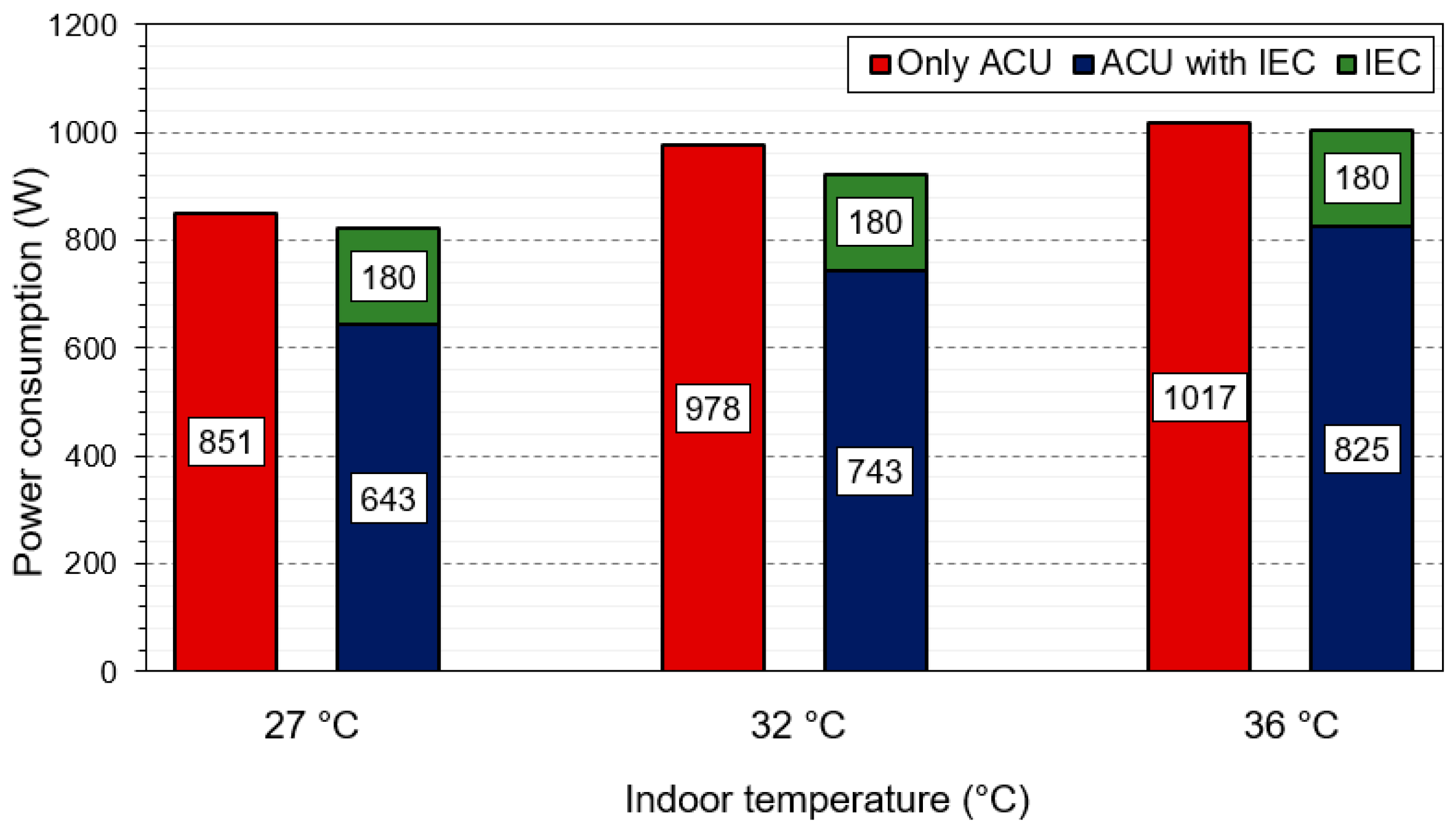
(3)
The average total power consumption of the ACU with the IEC decreased by 3.20%, 8.60%, and 1.13% at 27 °C, 32 °C, and 36 °C, respectively, compared to the ACU alone.
(4)
The average COP of the ACU with the IEC was 2.13, 2.08, and 1.92 at 27 °C, 32 °C, and 36 °C, respectively, compared to 2.06, 1.74, and 1.79 for the ACU alone, indicating increases of 3.42%, 19.5%, and 7.39%.
These results indicate that integrating an IEC with both the condenser and evaporator of an ACU enhances its performance. In addition, the high-performance ACU integrated with the IEC developed in this study is intended for use in existing buildings to reduce the cooling energy consumption. Future research will analyze the application of the proposed ACU with a baffled IEC to existing commercial and residential buildings, to assess the degree of energy savings and evaluate its economic aspects.

Author Contributions

Conceptualization, S.-B.K.; Methodology, S.-B.K., H.-U.C. and K.-H.C.; Investigation, K.-A.M. and H.-U.C.; Resources, K.-H.C.; Data curation, K.-A.M.; Writing—original draft, S.-B.K.; Writing—review & editing, H.-U.C. and K.-H.C. All authors have read and agreed to the published version of the manuscript.

Funding

This research received no external funding.

Data Availability Statement

The original contributions presented in the study are included in the article, further inquiries can be directed to the corresponding author.

Conflicts of Interest

The authors declare no conflict of interest.

Abbreviations

Nomenclature
A Area (m2)
T Temperature (°C)
h Height (m)
l Length (m)
m Mass flow rate (kg/s)
p Pitch (m)
tThickness (m)
w Width (m)
m ˙ Mass flow rate (kg/s)
c p Heat capacity (J/kg·K)
RH Relative humidity (%)
Q Cooling capacity (W)
W Power consumption (W)
COP Coefficient of performance (-)
Subscripts
a Air
ac Air channel
ACU Air conditioning unit
b Baffle
d Dry channel
eva Evaporator
fan Fan
in Inlet
out Outlet
pump Pump

References

  1. Campaniço, H.; Soares, P.M.M.; Hollmuller, P.; Cardoso, R.M. Climatic Cooling Potential and Building Cooling Demand Savings: High Resolution Spatiotemporal Analysis of Direct Ventilation and Evaporative Cooling for the Iberian Peninsula. Renew. Energy 2016, 85, 766–776. [Google Scholar] [CrossRef]
  2. González-Torres, M.; Pérez-Lombard, L.; Coronel, J.F.; Maestre, I.R.; Yan, D. A Review on Buildings Energy Information: Trends, End-Uses, Fuels and Drivers. Energy Rep. 2022, 8, 626–637. [Google Scholar] [CrossRef]
  3. Santamouris, M. Cooling the Buildings—Past, Present and Future. Energy Build. 2016, 128, 617–638. [Google Scholar] [CrossRef]
  4. Pescod, D. Heat Exchanger for Energy Saving in an Air-Conditioning Plant. ASHRAE Trans. 1979, 85, 238–251. [Google Scholar]
  5. Cui, X.; Chua, K.J.; Islam, M.R.; Yang, W.M. Fundamental Formulation of a Modified LMTD Method to Study Indirect Evaporative Heat Exchangers. Energy Convers. Manag. 2014, 88, 372–381. [Google Scholar] [CrossRef]
  6. Pandelidis, D.; Anisimov, S.; Worek, W.M. Performance Study of Counter-Flow Indirect Evaporative Air Coolers. Energy Build. 2015, 109, 53–64. [Google Scholar] [CrossRef]
  7. Kabeel, A.E.; Abdelgaied, M. Numerical and Experimental Investigation of a Novel Configuration of Indirect Evaporative Cooler with Internal Baffles. Energy Convers. Manag. 2016, 126, 526–536. [Google Scholar] [CrossRef]
  8. Chen, Y.; Luo, Y.; Yang, H. A Simplified Analytical Model for Indirect Evaporative Cooling Considering Condensation from Fresh Air: Development and Application. Energy Build. 2015, 108, 387–400. [Google Scholar] [CrossRef]
  9. Chen, Y.; Yang, H.; Luo, Y. Parameter Sensitivity Analysis and Configuration Optimization of Indirect Evaporative Cooler (IEC) Considering Condensation. Appl. Energy 2017, 194, 440–453. [Google Scholar] [CrossRef]
  10. Min, Y.; Chen, Y.; Yang, H. Numerical Study on Indirect Evaporative Coolers Considering Condensation: A Thorough Comparison between Cross Flow and Counter Flow. Int. J. Heat Mass Transf. 2019, 131, 472–486. [Google Scholar] [CrossRef]
  11. Shi, W.; Min, Y.; Chen, Y.; Yang, H. Development of a Three-Dimensional Numerical Model of Indirect Evaporative Cooler Incorporating with Air Dehumidification. Int. J. Heat Mass Transf. 2022, 185, 122316. [Google Scholar] [CrossRef]
  12. Duan, Z.; Zhan, C.; Zhang, X.; Mustafa, M.; Zhao, X.; Alimohammadisagvand, B.; Hasan, A. Indirect Evaporative Cooling: Past, Present and Future Potentials. Renew. Sustain. Energy Rev. 2012, 16, 6823–6850. [Google Scholar] [CrossRef]
  13. Porumb, B.; Ungureşan, P.; Tutunaru, L.F.; Şerban, A.; BǍlan, M. A Review of Indirect Evaporative Cooling Technology. Energy Procedia 2016, 85, 461–471. [Google Scholar] [CrossRef]
  14. Yang, H.; Shi, W.; Chen, Y.; Min, Y. Research Development of Indirect Evaporative Cooling Technology: An Updated Review. Renew. Sustain. Energy Rev. 2021, 145, 111082. [Google Scholar] [CrossRef]
  15. Sajjad, U.; Abbas, N.; Hamid, K.; Abbas, S.; Hussain, I.; Ammar, S.M.; Sultan, M.; Ali, H.M.; Hussain, M.; Rehman, T.U.; et al. A Review of Recent Advances in Indirect Evaporative Cooling Technology. Int. Commun. Heat Mass Transf. 2021, 122, 105140. [Google Scholar] [CrossRef]
  16. Mohammed, R.H.; El-Morsi, M.; Abdelaziz, O. Indirect Evaporative Cooling for Buildings: A Comprehensive Patents Review. J. Build. Eng. 2022, 50, 104158. [Google Scholar] [CrossRef]
  17. Xu, P.; Ma, X.; Zhao, X.; Fancey, K. Experimental Investigation of a Super Performance Dew Point Air Cooler. Appl. Energy 2017, 203, 761–777. [Google Scholar] [CrossRef]
  18. Chen, Q.; Kum Ja, M.; Burhan, M.; Akhtar, F.H.; Shahzad, M.W.; Ybyraiymkul, D.; Ng, K.C. A Hybrid Indirect Evaporative Cooling-Mechanical Vapor Compression Process for Energy-Efficient Air Conditioning. Energy Convers. Manag. 2021, 248, 114798. [Google Scholar] [CrossRef]
  19. Wang, J.; Lu, J.; Li, W.; Zeng, C.; Shi, F. Numerical Study on Performance of a Hybrid Indirect Evaporative Cooling Heat Recovery Heat Pump Ventilator as Applied in Different Climatic Regions of China. Energy 2022, 239, 122431. [Google Scholar] [CrossRef]
  20. Wang, T.; Sheng, C.; Nnanna, A.G.A. Experimental Investigation of Air Conditioning System Using Evaporative Cooling Condenser. Energy Build. 2014, 81, 435–443. [Google Scholar] [CrossRef]
  21. Kim, B.J.; Jo, S.Y.; Jeong, J.W. Energy Performance Enhancement in Air-Source Heat Pump with a Direct Evaporative Cooler-Applied Condenser. Case Stud. Therm. Eng. 2022, 35, 102137. [Google Scholar] [CrossRef]
  22. Yan, H.; Chen, Y.; Min, Y. Performance Analysis of Small-Scale Direct Expansion Air Conditioning System with Indirect Evaporative Cooler as Dedicated Ventilator. Build. Environ. 2022, 208, 108603. [Google Scholar] [CrossRef]
  23. Yan, H.; Chen, Y.; Min, Y.; Pan, Y. An Adaptive Controller Based Dynamic Simulation of Household Air-Conditioner with Indirect Evaporative Cooler as Dedicated Outdoor Air System. Energy Build. 2022, 274, 112454. [Google Scholar] [CrossRef]
  24. Li, W.; Shi, W.; Wang, J.; Li, Y.; Lu, J. Experimental Study of a Novel Household Exhaust Air Heat Pump Enhanced by Indirect Evaporative Cooling. Energy Build. 2021, 236, 110808. [Google Scholar] [CrossRef]
  25. Martínez, P.; Ruiz, J.; Cutillas, C.G.; Martínez, P.J.; Kaiser, A.S.; Lucas, M. Experimental Study on Energy Performance of a Split Air-Conditioner by Using Variable Thickness Evaporative Cooling Pads Coupled to the Condenser. Appl. Therm. Eng. 2016, 105, 1041–1050. [Google Scholar] [CrossRef]
  26. Ketwong, W.; Deethayat, T.; Kiatsiriroat, T. Performance Enhancement of Air Conditioner in Hot Climate by Condenser Cooling with Cool Air Generated by Direct Evaporative Cooling. Case Stud. Therm. Eng. 2021, 26, 101127. [Google Scholar] [CrossRef]
  27. Zhang, J.; Diao, Y.H.; Zhao, Y.H.; Zhang, Y.N. An Experimental Study of the Characteristics of Fluid Flow and Heat Transfer in the Multiport Microchannel Flat Tube. Appl. Therm. Eng. 2014, 65, 209–218. [Google Scholar] [CrossRef]
Figure 1. Schematic diagram of baffled IEC: (a) 3D view, (b) side view.
Energies 17 03231 g001
Figure 2. Schematic of the proposed ACU with a baffled IEC.
Energies 17 03231 g002
Figure 3. Actual view of the proposed ACU with a baffled IEC.
Energies 17 03231 g003
Figure 4. Actual experimental environment and measurement location of the ACU with a baffled IEC: (a) Actual view, (b) measurement location.
Energies 17 03231 g004
Figure 5. Performance of IEC for various indoor air temperatures: (a) air temperature difference, (b) cooling capacity, (c) COP.
Energies 17 03231 g005
Figure 6. Air temperatures of ACU with IEC during the test period for various indoor air temperatures: (a) 27 °C (b) 32 °C, (c) 36 °C.
Energies 17 03231 g006
Figure 7. Cooling capacity of ACU with IEC at various indoor air temperatures.
Energies 17 03231 g007
Figure 8. Power consumption of ACU with IEC at various indoor air temperatures.
Energies 17 03231 g008
Figure 9. COP of ACU with IEC at various indoor air temperatures.
Energies 17 03231 g009
Table 1. Summary of studies on various IEC integrations.
Ref.Analysis
Method
Apparatus
Setup
Highlights
Chen et al.
[18]
Experiment and NumericalIEC + AHUExperimental study of an IEC operating with room exhaust air in the wet channels and a numerical evaluation of the energy-saving potential of the EC–MVC under a wide range of outdoor air conditions.
Li et al.
[24]
ExperimentIEC + VentilatorExperimental study combining the technical advantages of heat recovery in IECs and the evaporative condenser of a ventilator.
Wang et al.
[19]
NumericalIEC + VentilatorNumerical study of a TRNSYS–Matlab model used to evaluate the ventilator’s adaptability in a public building.
Wang et al.
[20]
ExperimentDEC + ACUExperimental study conducted on a hybrid DEC–condenser located in an ACU.
Martinez et al.
[25]
ExperimentDEC + ACUNumerical study calculating the optimal cooling pad thickness that maximizes the overall ACU performance under different ambient conditions.
Ketwong et al.
[26]
NumericalDEC + ACUNumerical study on the condenser cooling of an ACU by the cool air generated by a DEC to improve air conditioner performance.
Kim et al.
[21]
NumericalDEC + ACUNumerical study investigating the optimal operation strategy of an ACU system with a EDC installed in an office building.
Yan et al.
[22,23]
NumericalIEC + ACUNumerical study of a system that initially cools air drawn from the external environment using an IEC, subsequently integrating it with the evaporator of an ACU.
Present studyExperimentIEC + ACUExperimental study of a system that integrates an ACU with a baffled IEC, which is simultaneously connected to both a condenser and evaporator.
Table 2. Geometrical characteristics of the baffle and IEC.
ParameterValue
IECLength ( l I E C ) 900 mm
Width ( w I E C ) 210 mm
Height ( h I E C ) 600 mm
Air channelLength ( l a c ) 90 mm
Height ( h a c )5 mm
BaffleHeight ( h b )2 mm
Width ( w b )5 mm
Pitch ( p b )116 mm
Table 3. Specifications of the measurement devices.
Measurement DeviceModelRangeUncertainty
Temperature and humidity sensorGHP-100T0~70 °C
0~100% (RH)
±0.75 °C
±2%
AnemometerKanomax 6531-2G0.01~9.99 m/s±0.015%
PowermeterPW33367.5 W~20 kW±0.1%
Table 4. Uncertainties of parameters for each experimental condition.
ParameterUncertainty
Q I E C ±2.26%
Q A C U ±2.26%
W t o t a l ±0.17%
C O P I E C ±2.27%
C O P A C U ±2.27%
C O P T o t a l ±2.28%
Disclaimer/Publisher’s Note: The statements, opinions and data contained in all publications are solely those of the individual author(s) and contributor(s) and not of MDPI and/or the editor(s). MDPI and/or the editor(s) disclaim responsibility for any injury to people or property resulting from any ideas, methods, instructions or products referred to in the content.

