Abstract
In weak grid, feedforward of grid voltage control is widely used to effectively suppress grid-side current distortion of inverters caused by harmonics in point of common coupling (PCC) voltage. However, due to its introduction of a positive feedback loop related to the grid impedance, it results in a significant reduction in the system phase margin. In view of this, in this paper, the output impedance of a three-phase LCL grid-connected inverter under a quasi-proportional resonant (QPR) controller is first modeled. Instead of the traditional grid voltage feedforward control strategy, a band-pass filter is added to the grid voltage feedforward channel. Secondly, a multi-objective constraint method is proposed to make improvements to the feedforward function. Then, a multi-objective constraint function is established with the constraints of base-wave current tracking performance, system stability margin, and low-frequency amplitude, and the feasibility of its function optimization design method is verified. Theoretical analysis shows that the optimized grid voltage feedforward control strategy can effectively reshape the phase characteristics of the system output impedance, which greatly broadens the adaptation range of the system to the grid impedance. Finally, the effectiveness of the proposed control strategy is verified by building a semi-physical simulation experimental platform based on RT-LAB OP4510.
1. Introduction
In recent years, as the world attaches great importance to renewable energy sources such as solar energy and wind energy, the proportion of distributed generation systems in the future power grid will continue to increase [1,2]. Grid-connected inverters as an important interface for distributed generation and necessary equipment for power quality management, such as new energy grid-connected inverters [3], active power filter (APF) [4], and Static Var Generator (SVG) [5], etc., play a crucial role in the construction of the smart grid.
However, with the wide distribution of distributed power sources as well as users, low-voltage transmission and distribution lines tend to be long, and the grid impedance becomes non-negligible under the combined influence of line impedance and transformer leakage inductance, in addition to the fact that the actual grid increasingly exhibits weak grid characteristics due to the presence of severe background harmonics in the grid-connected voltage [6,7]. In order to reduce the grid-connected current harmonics and the size, weight and cost of grid-connected filters, LCL filters are usually used [8]. However, the LCL inverter has resonant characteristics, and the phase is prone to −180° jump at the resonant spike crossing 0 dB in the grid-side current feedback control, resulting in system instability, which is generally suppressed by passive damping [9,10,11] or active damping [12,13,14,15] methods. Although the passive damping method can effectively suppress the resonance peaks of the LCL filter, it introduces additional system losses and affects the service life of the inverter. The active damping method simply introduces an algorithm into the controller and does not require an actual resistor to be connected to the circuit, which does not generate additional system losses and also effectively suppresses resonance peaks. Therefore, in this paper, a capacitive current active damping strategy under QPR control is used [16], which not only enhances the fundamental gain of the system and reduces the steady state error, but also effectively suppresses the resonance peaks of the LCL filter [17].
Grid voltage feedforward control [18,19,20] can offset the influence of background harmonics of grid voltage on the grid-connected current, and it is widely used because it has the advantages of suppressing the inrush current during the startup of the grid-connected inverter and reducing the steady state error of the grid-connected current. However, in the weak grid case, the grid voltage feedforward control introduces an additional feedback loop related to the grid impedance, which drastically reduces the phase angle margin of the grid-connected inverter and poses a serious threat to the quality and stability of the grid-connected current of the grid-connected inverter. For this reason, there are some studies from this point of view that proposed to set different transfer functions on this positive feedback channel to weaken the influence of positive feedback and improve the stability of the grid-connected inverter. For example, in [21], a second-order generalized integrator (SOGI) centered on the fundamental frequency is proposed to be added to the grid voltage positive feedback channel. The system stability is improved due to the use of SOGI to compensate the phase margin of the grid-connected inverter. In [22], a new grid voltage feedforward adaptive algorithm is proposed to make it work well in the presence of grid impedance variations. A grid voltage weighted feedforward scheme based on multiple resonant components is proposed in [23], which introduces a series of quasi-resonant components in the full feedforward path of the grid voltage such that only the background harmonics in the grid voltage are fed forward. Additionally, in Reference [24], a weighted proportional-derivative (PD) PCC voltage feedforward scheme is proposed. By appropriately adjusting the weighting coefficients of the two feedforward parameters, the real part of the inverter output impedance becomes non-negative over a sampling frequency range of up to 0.47 times, harvesting satisfying passivity. In addition to this, [25] proposed to use grid voltage instead of PCC voltage for feedforward and considering that it is more difficult to detect the real grid voltage directly, a method to extract the grid voltage from the detected PCC voltage is proposed to realize the suggested feedforward scheme, which improves the situation that PCC voltage feedforward makes the grid-connected inverter unstable in weak grid due to the effect of delay.
In summary, although there are various methods to improve the grid voltage feedforward control, these control strategies are an impedance reshaping of the system output impedance. These improvement strategies mainly improve the grid voltage feedforward channel, which needs to be realized by adding various control links, but the design of the control parameters is seldom from a macro point of view to control and link the various indicators of the system as a whole; thus, the accuracy and universality of the control parameters are still to be solved urgently.
Based on the above problems, this paper takes the three-phase LCL grid-connected inverter as the research object. Firstly, the control system is modeled and secondly, a band-pass filter is added into the grid voltage feedforward channel [26] to perform impedance reshaping of the system to improve the robustness of the inverter against grid impedance variations. Furthermore, a multi-objective constraint method is proposed to optimize the band-pass filter parameters in terms of base-wave current tracking performance, system stability margin and low-frequency amplitude constraints for grid voltage feedforward in weak grid. The main contributions of this study are summarized as follows:
(1) Based on the impedance stability criterion analysis method, this study analyzes the causes of system instability caused by grid voltage feedforward under a weak grid, and explains through the bode plot analysis that the system instability is due to the fact that the equivalent shunt virtual impedance correction introduced by the grid voltage feedforward will change the originally designed system, which leads to the phase lag of the original output impedance of the inverter, and the system is destabilized.
(2) Improvements are made to the grid voltage feedforward channel by adding a band-pass filtering link to its positive feedback channel, analyzing the cumbersomeness of its traditional parameter design method, and proposing a multi-objective constraint method to optimize the design of its parameters, so that the optimized system can directly satisfy the various grid-connected requirements, and enhance the stability of the system under the weak grid without affecting the performance of current tracking.
The remainder of this paper is organized as follows: Section 2 models and briefly describes the three-phase LCL grid-connected inverter system and derives an expression for the output impedance of the inverter by means of a structure-diagram equivalent transformation. Section 3 elucidates the reasons why grid voltage feedforward destabilizes the system in weak grid. Section 4 describes and analyzes the inclusion of a band-pass filter in the feedforward channel. Section 5 proposes a multi-objective constrained optimization of the band-pass filter parameters and analyzes the stability of the optimized system. Section 6 verifies the feasibility and effectiveness of the proposed multi-objective constrained optimization method by building a semi-physical simulation experimental platform based on RT-LAB. Finally, Section 7 summarizes the whole passage.
2. Establishment of Mathematical Model for LCL Grid-Connected Inverter
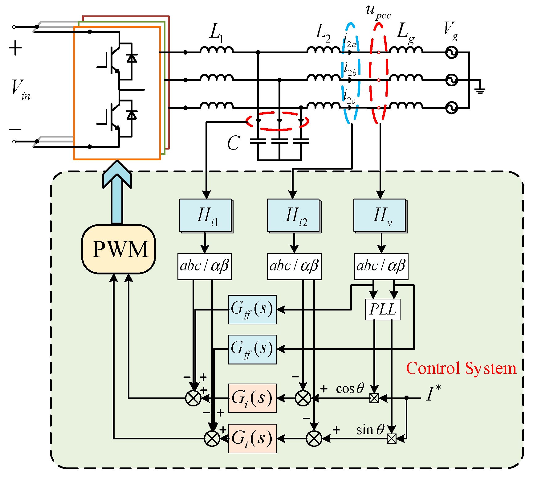
Figure 1 shows a schematic diagram of a three-phase LCL grid-connected inverter and its control system. The inverter-side inductance L1, the grid-side inductance L2, and the filter capacitor C form the LCL filter. Since the grid-side grid resistance is beneficial to the stability of the system, only the role of the grid inductance Lg is considered when analyzing the effect of the grid impedance on the stability of the LCL grid-connected inverter. The grid-connected reference current I* of the inverter is mainly given by the power control of the inverter or the DC-side voltage control loop. Here, the given value of the reference current is kept constant, and in the control system, in order to make the grid-connected current in phase with the grid voltage, it is necessary to utilize the phase-locked loop (PLL) to sample and analyze the PCC voltage, so as to obtain real-time phase information θ of the grid voltage. Hi1 is the active damping coefficient of the capacitor current, Hi2 is the sampling coefficient of grid current, and Hv is the grid voltage sampling coefficient, Gff(s) is the feedforward control transfer function, and Gi(s) is the current controller transfer function.
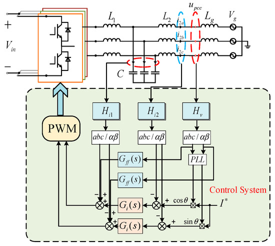
Figure 1.
LCL grid-connected inverter and control system schematic diagram.
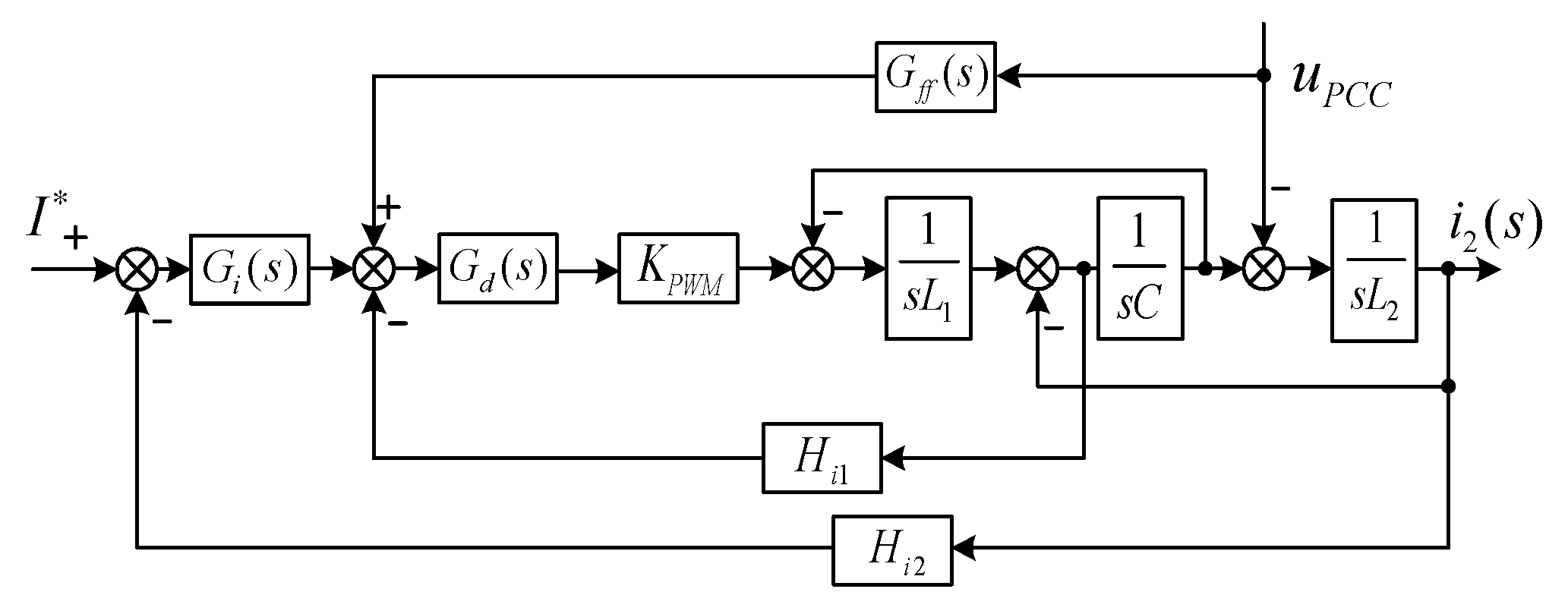
The three-phase LCL grid-connected inverter mathematical model is transformed into a two-phase stationary coordinate system after coordinate transformation. At this time, the two-phase currents are independent of each other, and there is no coupling relationship. Take the double closed-loop control structure with grid-connected current i2 feedback as an example and, at this time, the control block diagram of Figure 1 on the α axis can be simplified as shown in Figure 2.
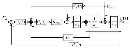
Figure 2.
System control block diagram.
In Figure 2, Kpwm is the equivalent proportional gain of the inverter bridge, and there is Kpwm ≈ Vin (when the peak value of the triangular carrier is 1). In addition, most of the feedforward links use proportional feedforward, when the grid voltage proportional feedforward link Gff(s) ≈ 1/Kpwm.
The mathematical model of the inverter in the two-phase stationary coordinate system is independent of each other. There is no coupling relationship, but the control variables are sinusoidal and the traditional proportional-integral (PI) controller cannot be achieved without static control, so the QPR controller is used. The QPR controller can be in the two-phase stationary coordinate system to achieve the same control effect as the rotating coordinate system of the PI controller. The transfer function of the QPR controller is given by
In Equation (1), kp, kr are the proportional and resonance parameters of the QPR controller. ωc is the control bandwidth of the controller. ω0 is the fundamental angular frequency of the grid voltage.
When the grid-connected inverter is digitally controlled, there are delays in the system introduced by digital computation, sampling switches, and zero-order holder, and the equivalent transfer function is shown as
In Equation (2), Ts is the system sampling period.
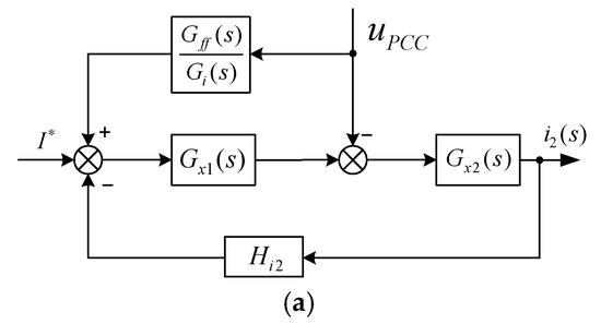
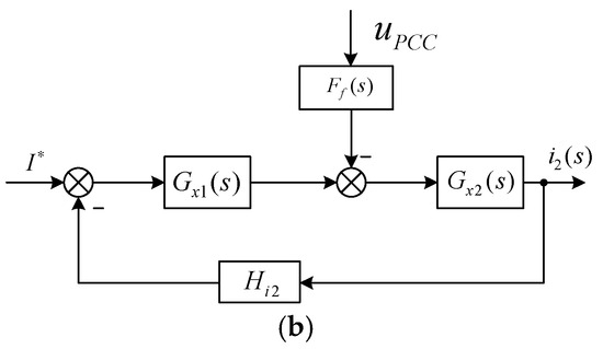
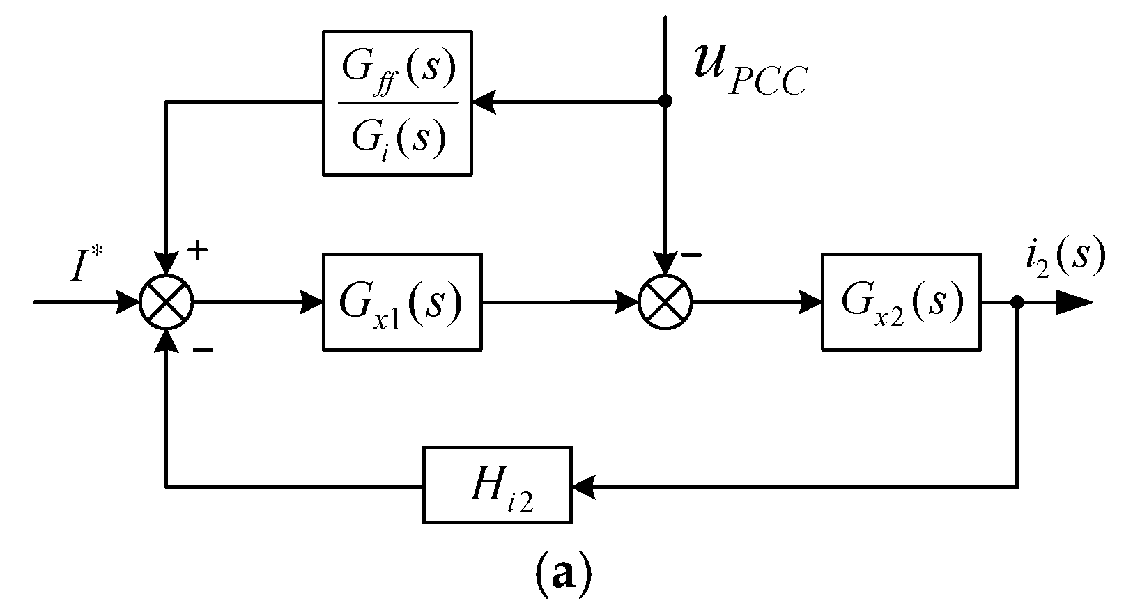
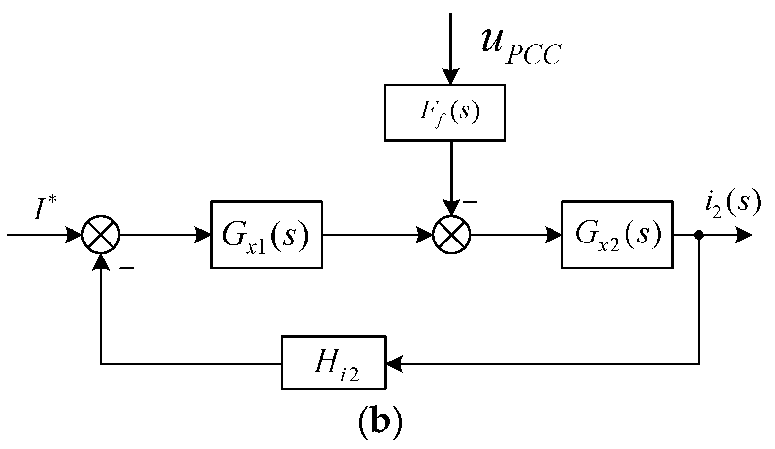
Figure 3.
System control block diagram equivalent transformation. (a) with feedforward channel; (b) merge feedforward channel.
The loop gain T0 and the grid-connected current i2 of the system can be expressed as
Then, the output impedance Z0(s) of the inverter containing the grid voltage feedforward control link is derived as
when there is no grid voltage feedforward in the control system, the Ff(s) link is taken to be 1. At this time, the inverter output impedance Z01(s) is shown as Equation (9).
In order to facilitate the analysis of the subsequent problems, this paper firstly gives a three-phase LCL grid-connected inverter with a rated power of 20 kW based on the relevant design guidelines, and the relevant technical parameters are shown in Table 1.

Table 1.
Parameters of model.
3. System Stability Analysis in Weak Grid
When the grid is in weak grid conditions, the fluctuation range of its equivalent impedance is large, which can easily lead to inverter instability. Secondly, according to the above analysis, when the traditional grid voltage proportional feedforward is used to offset the influence of grid voltage on the incoming current, the feedforward channel introduces an additional positive feedback loop for the incoming current, and under the weak grid conditions, the introduction of this control strategy will lead to a drastic reduction in the phase angle margin of the system, which seriously threatens the stability of the grid-connected system. The causes of system destabilization will be discussed in the following passage.
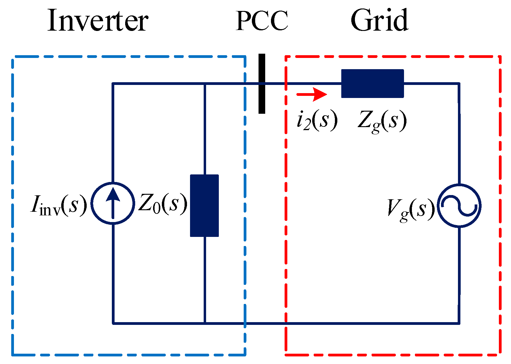
Since the current controller is used in the paper, the actual output current is equal to the given value, thus when analyzing the stability of the grid-connected inverter under grid impedance, the inverter is equated to a constant current source i0 and an equivalent output impedance Z0 connected in parallel with it, and the specific equivalent circuit diagram is shown in Figure 4.
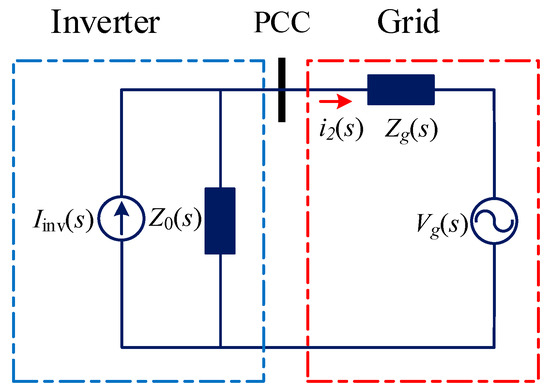
Figure 4.
Impedance model of the grid-connected inverter.
In Equation (10), Zg(s) is the grid impedance. In order to better study the effect of grid impedance on the stability of the grid-connected inverter system, Zg(s) is only taken as the inductive part. From [27], the following two conditions need to be fulfilled in order to ensure that the inverter remains stable under conditions of varying grid impedance:
(1) When Zg(s) = 0, it is necessary to ensure that the inverter is stabilized;
(2) When Zg(s) ≠ 0, it is necessary to ensure that Zg(s)/Z0(s) satisfies the impedance stabilization criterion.
The system is stabilized if Zg(s) and Z0(s) do not intersect or if the phase angle margin between Zg(s) and Z0(s) at the intersection frequency fs satisfies Equation (11).
Since Zg(s) is inductive, the phase is 90°, and referring to (11), we can obtain the phase relation equation of Z0(s) when the system is stabilized, as shown in Equation (12).
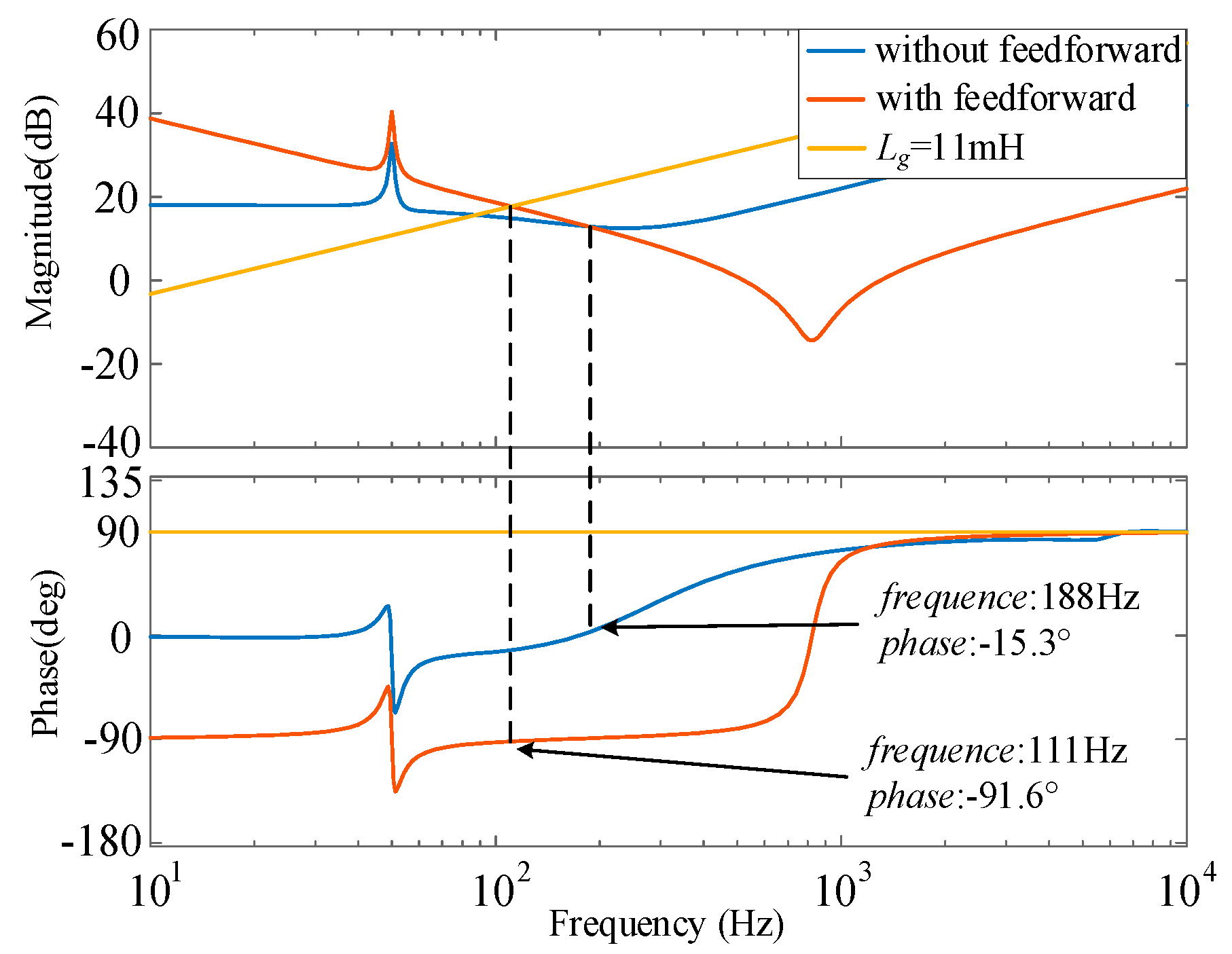
Based on the results obtained in the previous section, the bode plot of the inverter output impedance with and without grid voltage feedforward is plotted as shown in Figure 5.
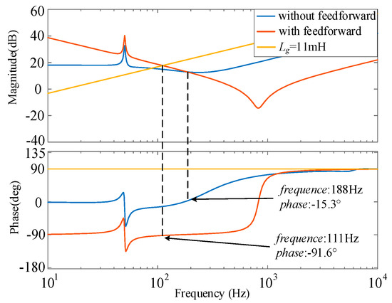
Figure 5.
Bode plot of inverter output impedance with and without grid voltage feedforward.
As can be seen in Figure 5, the amplitude of the output impedance in the low-frequency band increases dramatically after the addition of the grid voltage feedforward, and the phase characteristics lag dramatically. However, the stability margin of the system changes in the weak grid case. For example, in Figure 5, when the grid impedance is 11 mH, corresponding to the short circuit ratio SCR = 2, the phase margin of the grid-connected inverter system before adding grid voltage feedforward is about 74.7°, while after adding grid voltage feedforward, the phase is −91.6°, which makes the system unstable at this time according to the analysis above. In conclusion, the increase in amplitude, while improving the inverter’s ability to suppress background harmonics in the grid voltage, also poses a problem, which is that the lack of phase margin makes the grid-connected system much less stable. When the grid impedance in the weak grid case is non-negligible, the system is at risk of instability. In summary, regarding the reason for the instability of the grid-connected system caused by the traditional grid voltage feedforward method, the explanation from the perspective of output impedance is that the equivalent shunt virtual impedance correction introduced by the grid voltage feedforward will change the originally designed system, resulting in the phase lag of the original output impedance of the inverter.
4. Improved Feedforward Control Strategy Based on Band-pass Filter
According to the above analysis, the original intention of introducing proportional feedforward is to be able to effectively suppress the inverter grid-connected current distortion problem caused by the voltage harmonics at the point of common coupling (PCC), but after considering the weak grid, this control strategy will in turn reduce the overall phase margin of the system, resulting in system instability.
Therefore, to address the above problems, a band-pass filter is used in the proportional feedforward channel, so that this control can counteract the effect of grid voltage on the incoming current, while at the same time improve the overall phase margin of the system and broaden the system’s adaptability to the grid impedance.
In this passage, instead of using a conventional voltage-controlled voltage-source second-order band-pass filter composed of a single integrated operational amplifier, subsequent experiments use a band-pass filter (BPF) composed of a low-pass filter (LPF) and a high-pass filter (HPF) connected in series. The band-pass filter transfer function is given below as shown in Equation (13).
In Equation (13), K1, K2 are the gains of LPF and BPF, respectively, ω2 and ω1 are the upper and lower cutoff angular frequencies of BPF, K is its total gain, and ξ is the damping parameter (generally taking the value of 0.707).
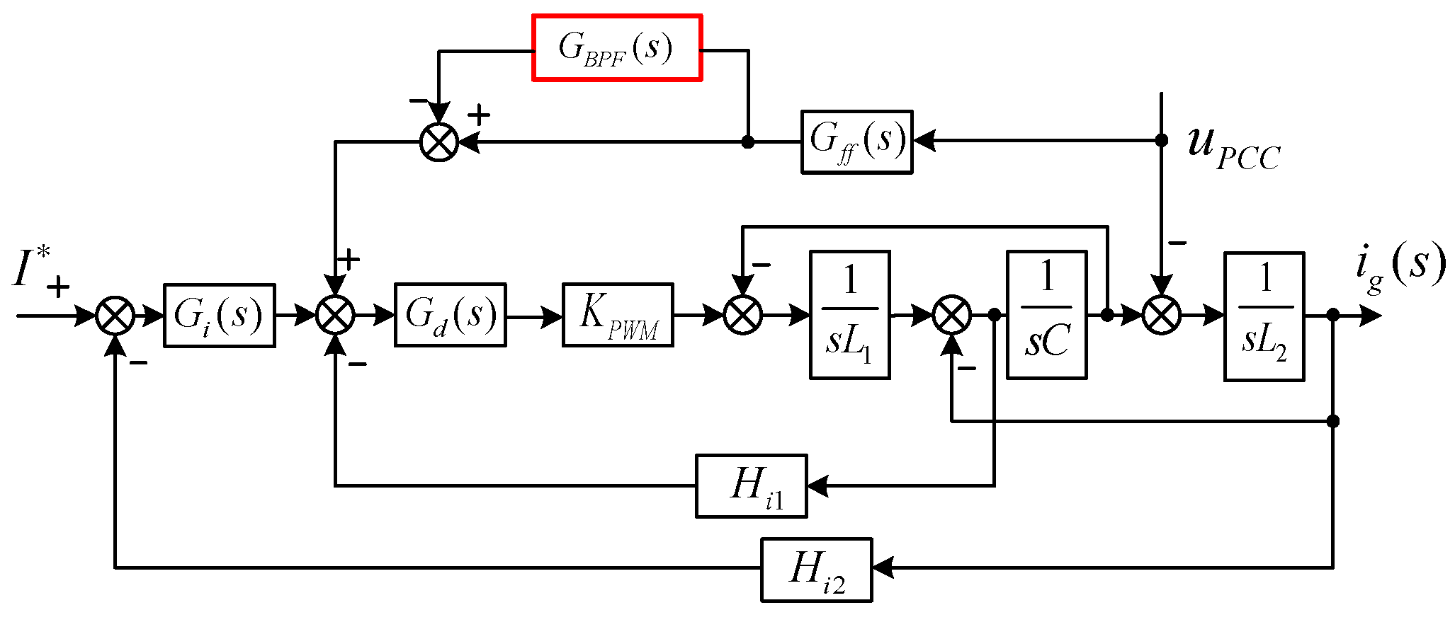
The system control block diagram after adding BPF is shown in Figure 6.
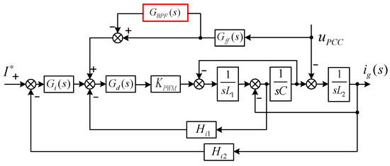
Figure 6.
System control block diagram with BPF.
The improved inverter output impedance Z03(s) can be derived from Figure 6 as shown in Equation (14)
Comparing Equations (8), (9), and (14), it can be seen that changing the feedforward link is actually changing the output impedance of the inverter for the purpose of impedance reshaping, and if the reshaped output impedance satisfies Equation (12), the original intention of the system design can be achieved.
In Table 1, the underlying parameters of the system have been given, but not the parameters of the BPF, which is now based on the basics of analog circuits to make a preliminary design of the BPF.
First, determine the center frequency f0 = 50 Hz and the bandwidth B is also set to 50 Hz at this time. With the quality factor Q = f0/B, determine the voltage amplification at all levels through the center frequency, so that the mode of the denominator of the voltage amplification multiplier is equal to 1.414 and obtain the lower cutoff frequency ω1 and the upper cutoff frequency ω2.
Here, only a simple design of the BPF is made. Usually, the gain of the BPF, if set too small cannot improve the phase margin of the inverter impedance in the mid-frequency band, while if set too large will lead to the amplitude of the amplitude–frequency curve of the inverter impedance amplitude reduction; the base wave gain is reduced, which is not conducive to the stability of the system. Here, the value of K is taken as 300. The upper and lower cutoff angular frequency is 4500 π and 100 π, respectively.
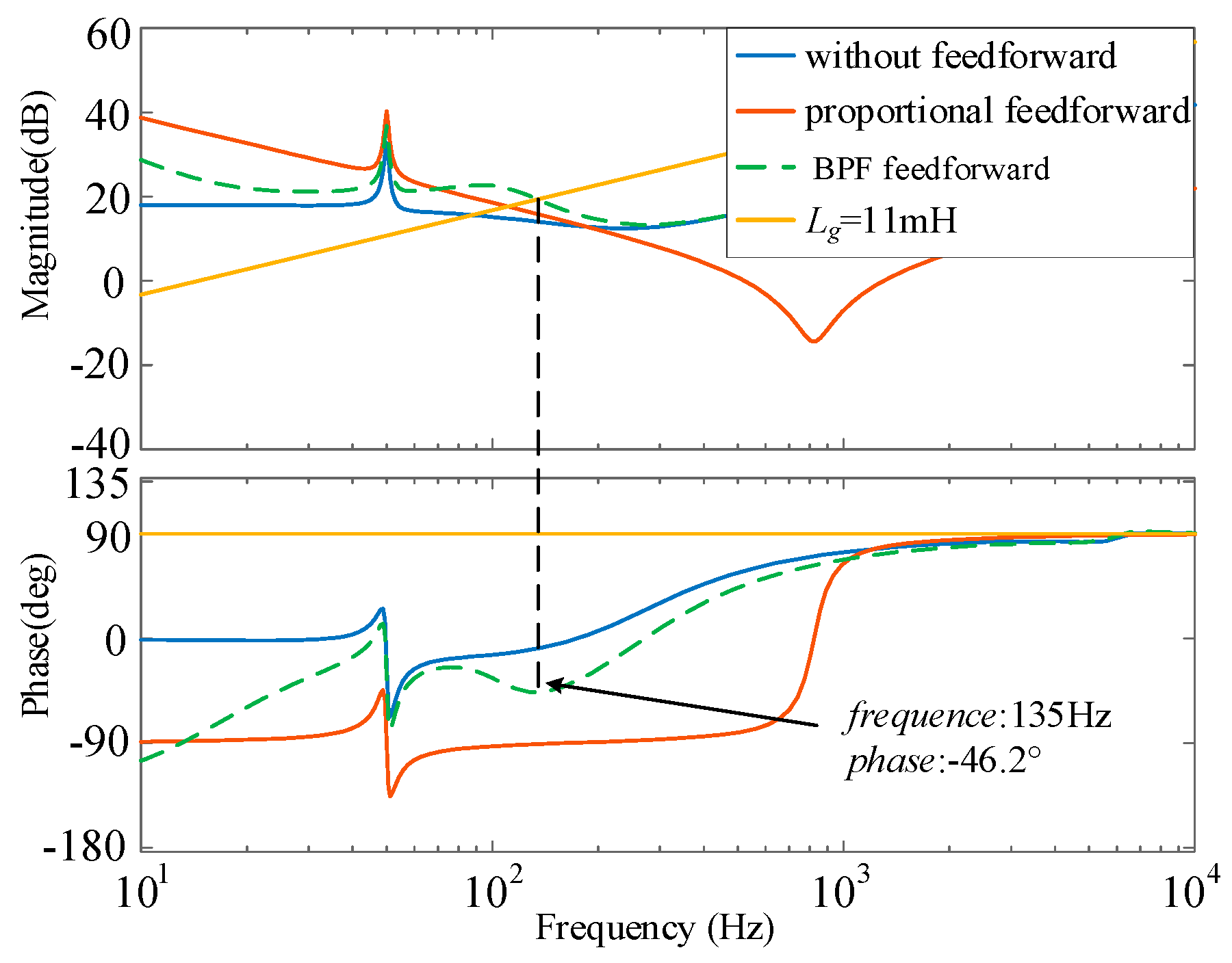
The given parameters are now brought into Equation (14) and the improved inverter output impedance bode plot is plotted as shown in Figure 7.
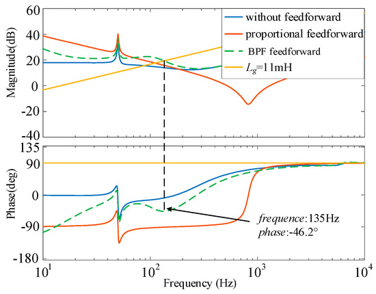
Figure 7.
Bode plot of output impedance of the improved inverter.
From Figure 7, it can be seen that the improved inverter output impedance Z03(s) possesses the same high impedance in the low-frequency band as that of Z01(s) without the addition of proportional feedforward, which retains the control system’s immunity to grid harmonic voltages, whereas under weak grid conditions, Z03(s) has a phase of greater than −90° at the frequency of intersection with the grid impedance and the system is in a stable state, which improves the system’s instability in the case of proportional feedforward.
In the above introduction, the system impedance is changed by incorporating a BPF to adapt to a wide range of variations in the grid impedance and to improve the robustness of the system. However, from the beginning, the BPF was designed by applying only the knowledge of analog circuits to its most basic functions, such as setting the voltage signals within the desired frequency range to pass through, setting the signals outside the frequency to attenuate quickly, and setting the quality factor to improve its frequency selective characteristics. However, when the BPF parameters are changed, its inverter output impedance Z03(s) is also changed, and substituting the designed BPF into Z03(s) is not so ideal for every set of data.
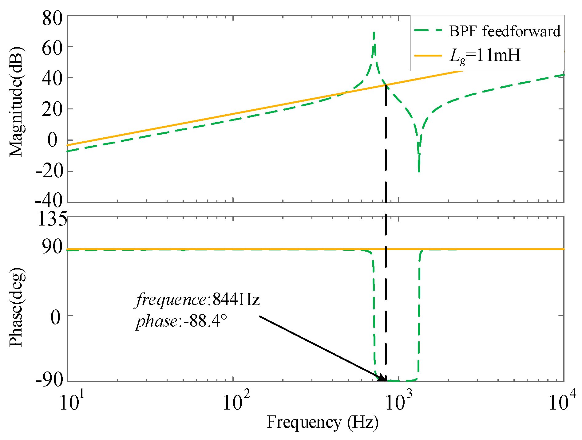
Figure 8 shows the bode plot of Z03(s) with a K value of 300 and upper and lower cutoff angular frequency of 2500 π and 100 π, respectively, which reduces the passband range of the BPF, and it can be seen from Figure 8 that from the design point of view of the filter, the parameters obtained from the design satisfy the requirements of filtering but do not satisfy the requirements of system stability. At this time, the inverter output impedance will appear to intersect the grid impedance several times. Moreover, at fs = 844 Hz, the phase is −88.4°, at which time the system is already in an unstable boundary state.
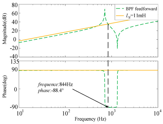
Figure 8.
Bode plot of inverter output impedance after changing BPF parameter.
In addition to this, if a physical BPF is used, its resistance and capacitance need to be designed, and substituting each calculated parameter into Z03(s) if it is found to be inappropriate and then carrying out the calculation again will greatly increase the workload.
5. Multi-Objective Constraint
In the previous section of the analysis, the method of improving the system margin was actually an impedance remodeling of the system. Methods for impedance remodeling are well established, and there are many remodeling methods for this aspect of the feedforward channel. For example, low-pass, band-pass, high-pass, band-stop, and complex filters are strung in the feedforward channel, and a phase correction link is added to the current-controlled forward channel, and so on. But whenever a new link is added, the parameters of the new link need to be designed. For example, the key parameter cutoff frequency of a complex filter is designed based on its dominant eigenvalue and remains without a necessary connection to the system.
For grid connection, according to national standards, there are numerous criteria in addition to keeping the system stable such as unit power factor grid connection, grid current total harmonic distortion (THD), base-wave current tracking performance, and so on. If it is possible to use the grid-connected conditions as a baseline to establish the relationship between each of the required performance indicators and the currently incorporated improvements, it is possible to design the ideal parameters in one step. When the system is subjected to large disturbances and wide-range variations, the system can still meet the requirements and be connected to the grid in that case because the design leaves a certain margin. In order to solve the above problems and claims, the three important parameters K, ω1, and ω2 in BPF are jointly optimized in this passage. Firstly, let K, ω1, and ω2 be X, Y and Z, respectively, then Equation (13) can be rewritten as
Then, the multi-objective constraint functions between the BPF parameters and the base-wave current tracking performance, system stability margin, and low-frequency amplitude constraints are established, and these constraint functions are used to find the BPF parameters that satisfy the system requirements, so that the output impedance of the inverter directly establishes a direct relationship with the grid-connection index of the system, which makes the method of impedance reshaping more intuitive.
5.1. Base-Wave Current Tracking Performance
Since the following analyses are performed at both low frequency (50 Hz) and intermediate frequency (1 kHz), the filter capacitance C is neglected, and the QPR controller in term Gi(s)Gd(s)KpwmHi2 has a nearly infinite gain at the base-wave, and the s(L1 + L2) term can be further neglected, and in this passage, the proportional feedforward is used for Gff(s).
Then, the output impedance of the improved inverter can be simplified as Z04(s).
In order to minimize the impact on the tracking performance of the base-wave current it is necessary to keep the characteristics at the base-wave unchanged before and after reshaping the output impedance of the inverter. For without grid voltage feedforward control, without grid voltage feedforward control in the strong grid case already meets the requirements of system stability and unit power factor grid connection. Therefore, for the introduction of the BPF feedforward, the base-wave characteristics of the feedforward control without grid voltage are used as a benchmark, and the base-wave is constrained in terms of both amplitude and phase.
5.1.1. Base-Wave Amplitude Constraint
Similarly, the inverter output impedance Z01(s) without grid voltage feedforward control can be simplified to Z05(s).
To keep the base-wave amplitude constant before and after impedance reshaping, (19) can be derived
Since the amplitude gain due to the delay link is one, it is negligible when considering the amplitude characteristic. Then, Equation (19) can be written as
supposing that
At this point, the base-wave amplitude can be approximated as unchanged. In Equation (21), AMerror-max is the ratio of the maximum amplitude of the base-wave. Accordingly, the constraint based on the amplitude error of the base-wave can be obtained.
For ease of reference below, Equations (23)–(25) are given
The constraint on the amplitude of the base-wave can then be written as
5.1.2. Base-Wave Phase Constraint
Assuming that there is an error PFerror in the grid-connected power factor of the system before and after the introduction of the BPF, ∆φ is the corresponding power factor error angle. The inverter is considered to achieve unit power factor grid connection if PFerror satisfies PFerror ≤ PFerror-max (PFerror-max is the maximum permissible power factor error). Then, the condition yields |∆φ| = ∆φmax. ∆φmax as the power factor error angle corresponding to PFerror-max.
When the base-wave phase constraint is considered, the delay link can no longer be ignored. Then, Equation (17) is rewritten as
The phase angle can be written as
For the case without BPF, the phase angle at the base-wave is counted as ΦZ01(jω0). According to Figure 5, its phase angle at the base-wave is −15°. To ensure that the phase angle offset of the base-wave after the introduction of the BPF is small at this point, it is necessary to satisfy Equation (29).
|∆φ| should be as small as possible so that its maximum value does not exceed ∆φmax. When |tan(∆φmax)| is extremely small, the power factor error PFerror-max can be considered to be approximately 0. At this point, the inverter unit power factor grid connection.
Based on the above constraint requirement, the base-wave phase error constraint on the output impedance of the inverter shown in Equation (30) can be obtained. There is no need to add a fundamental frequency phase correction link after considering this constraint.
AMerror-max = 3%, PFerror-max = 0.1% (correspond to ∆φmax = 2.56°). Then, the constraint on the tracking performance of the base-wave current can be obtained.
5.2. System Stability Margin
In order to ensure that the system based on grid voltage feedforward control still has a high stability margin under weak and very weak grid when using the multi-objective constraint method, the stability margin constraint is performed under the condition of SCR = 2 for very weak grid at this time. In practical engineering, the system can be considered to be stabilized with PM = 30° considering that there may be some phase error before and after the simplification of Equation (17). To further ensure that the system has sufficient stabilization margin, the system stability margin constraint is set at PM = 40° in this paper.
When SCR = 2, the intersection frequency fs of impedance Z04(s) with impedance Zg(s) is unknown. Therefore, the intersection frequency fs = 110 Hz of impedance Z0(s) and impedance Zg(s) is used instead. To ensure the effectiveness of this alternative, the intersection frequency of impedance Z04(s) and impedance Zg(s) is first constrained to be near or greater than fs.
The system output impedance intersection frequency constraint is given by
In Equation (31), ωg is the intersection angle frequency between the inverter output impedance and the grid impedance. When Equation (31) is satisfied, the intersection frequency of impedance Z04(s) and impedance Zg(s) can be considered to be fs or greater than fs.
The constraint on the stability margin of the system is given by
In Equation (32), Z04(jωg) is shown as
In Equation (33), aωg, bωg, cωg are obtained by replacing ω0 with ωg in Equations (23)–(25).
Substituting Equation (33) into Equation (32) yields the constraint on the stability margin of the system.
5.3. Low-Frequency Amplitude Constraint
After impedance reshaping, the impedance amplitude in the frequency band below the fundamental frequency of the inverter output impedance is unknown and is likely to be below 0 dB, resulting in multiple intersections with Zg(s), which is not conducive to system stability. Therefore, further optimized design of the reshaped inverter output impedance with low-frequency amplitude as a constraint is required.
The amplitude of GBPF(s) is continuously increasing in the range [0–50 Hz]. And considering that the gain of the QPR controller is mainly determined by the proportionality parameter kp, Gi(s) is equated here to the proportionality link kp. When considering amplitude below the fundamental frequency, Z04(s) can be simplified as
To ensure that the inverter output impedance below the fundamental frequency has no intersection with the amplitude of Zg(s), it is only necessary to ensure that the minimum value of the amplitude of Z04(s) below the fundamental frequency after reshaping is greater than the maximum value of the amplitude of Zg(s). From the above analysis, the minimum of the Z04(s) magnitude is obtained at ω0.
In order to improve the applicability of the constraint, take SCR = 2 for very weak grid condition here. At this point the grid impedance has an amplitude of 10 dB at 50 Hz, so take A as 10.
By combining the above considerations, then the constraint on the low-frequency amplitude of the system can be obtained.
Based on the constraints of Equations (26), (30), (31), (32), and (35), then the constraint space of each constraint with respect to X, Y, and Z under the 3D coordinate system can be obtained. The points that satisfy these constraint spaces are the values of X, Y, and Z that satisfy the requirements.
5.4. System Stability Analysis Based on Grid Voltage Feedforward under Multi-Objective Constraint
Based on the constraint space that has been obtained, further stability analysis of the proposed grid voltage feedforward based on the multi-objective constraint.
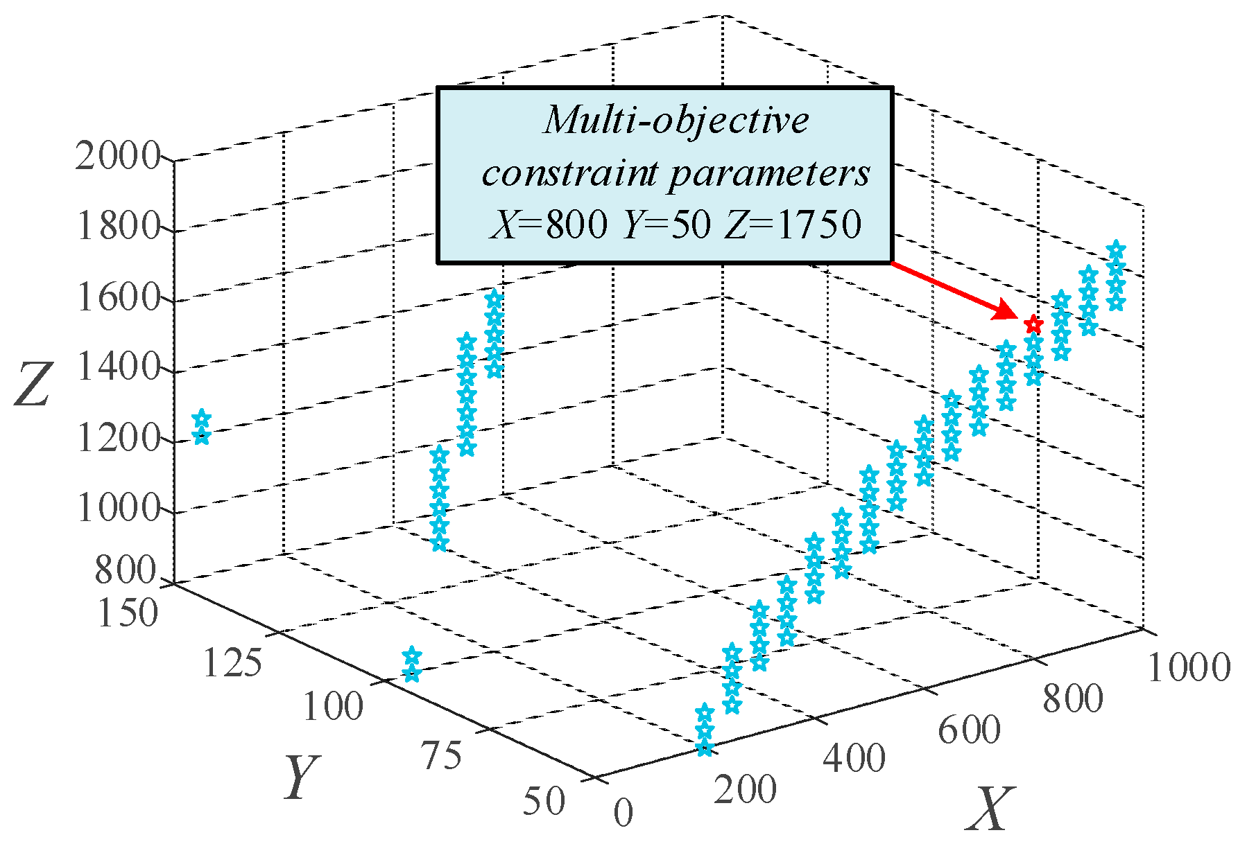
It can be seen that the five constraint equations will form five constraint ranges in the space, and taking the intersection of these five constraint ranges is the value of X, Y, and Z that satisfies the requirements as shown in Figure 9.
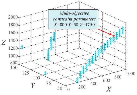
Figure 9.
Distribution of parameter values.
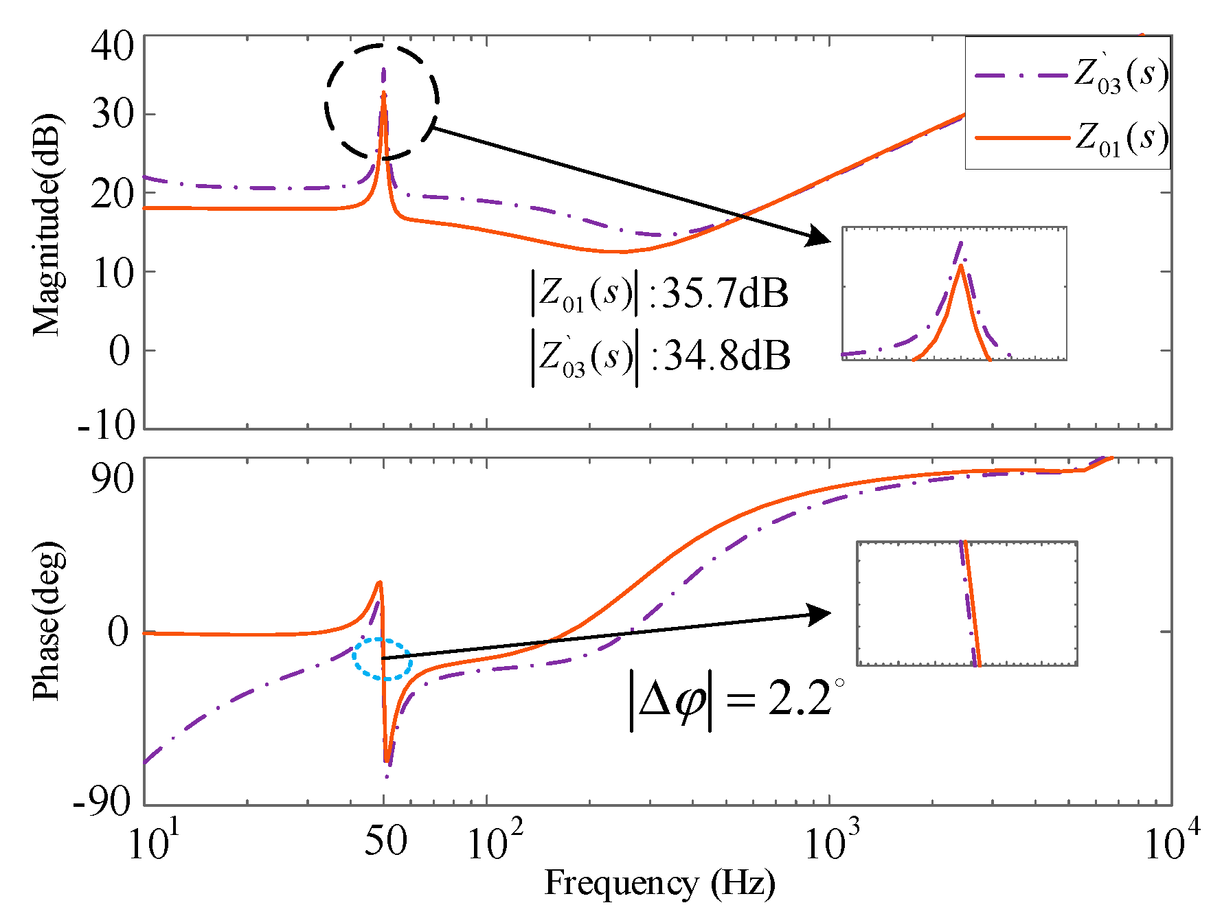
In this paper, we take the value of X = 800, Y = 50, Z = 1750 as an example to verify and analyze. The three parameters are substituted into Z03(s) to obtain the BPF feedforward inverter output impedance Z`03(s) under multi-objective constraint. Also analyzed under very weak grid is the plotting of the bode plot of Z01(s) and Z`03(s), as shown in Figure 10.
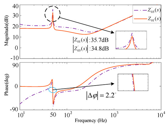
Figure 10.
Bode plot of Z01(s) and Z`03(s).
At this point, for the constraint, the base-wave amplitude ratio is 2.56%, less than AMerror-max, and the base-wave amplitude constraint is satisfied; the phase difference in the base wave is 2.2°, less than |∆φ| = ∆φmax = 2.56°. The grid-connected inverter can be considered to be grid-connected at a unit power factor and satisfies the base-wave phase constraint.
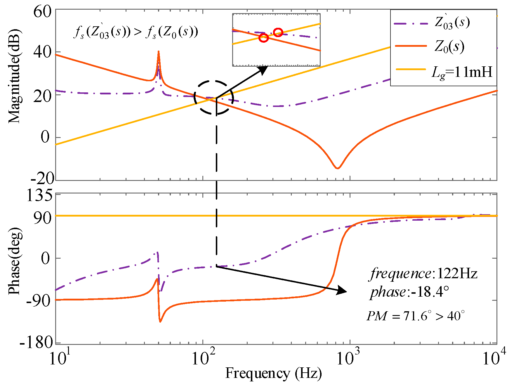
The bode plot of Z`03(s) and the inverter output impedance Z0(s) without the addition of BPF is plotted as shown in Figure 11 to verify the system stability margin constraint. From Figure 11, it can be seen that the intersection frequency of Z`03(s) with the grid impedance is larger than that of Z0(s) with the grid impedance, which satisfies the intersection frequency constraint. Secondly, the system stability margin after adding the multi-objective constraint reaches 71.6° greater than 40°, which satisfies the system stability margin constraint.
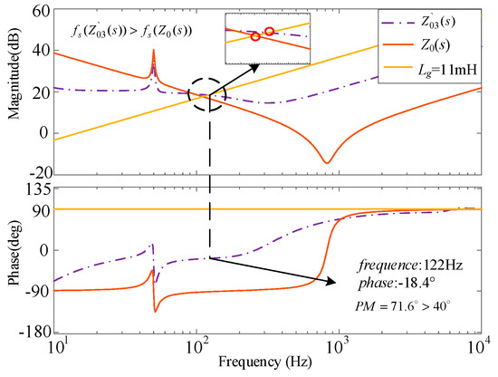
Figure 11.
Bode plot of Z0(s) and Z`03(s).
Besides, below the fundamental frequency of the system, there is no intersection between the grid impedance and the inverter output impedance, which ensures the stability of the system and satisfies the low-frequency amplitude constraint. The correctness of the selected values is verified.
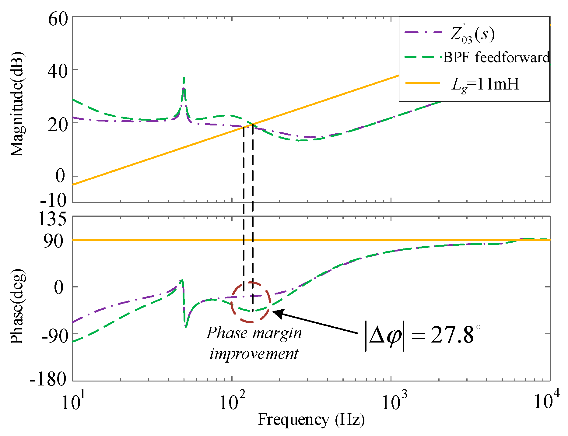
Figure 12 shows the bode plot of Z`03(s) and the inverter output impedance bode plot including BPF feedforward obtained according to the conventional design method in Section 3.
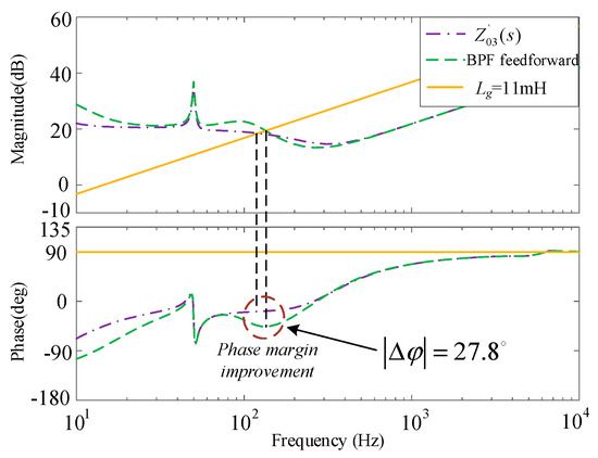
Figure 12.
Bode plot of Z03(s) and Z`03(s).
As can be seen in Figure 12, the system margin is improved by 27.8° compared to the case when the multi-objective constraint is not used, which greatly improves the stability of the system.
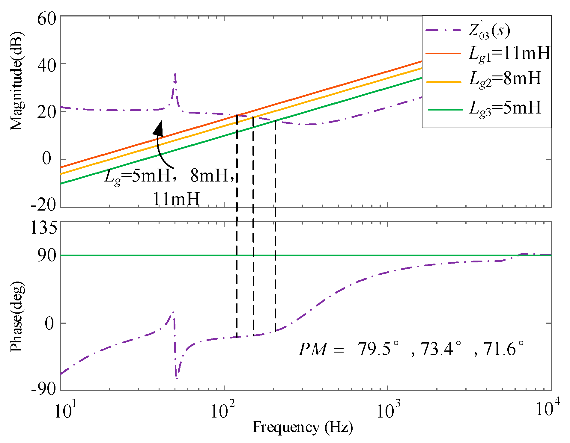
Plotting the bode plot of Z`03(s) and the bode plot of the grid impedance as it varies is shown in Figure 13.
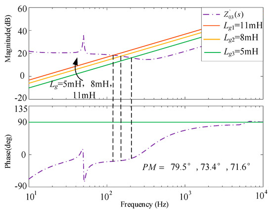
Figure 13.
Bode plot of Z`03(s) and Lg.
From Figure 13, it can be seen that when the grid impedance is varied, Lg is 5 mH, 8 mH, and 11 mH, respectively, and the system stability margin is 79.5°, 73.4°, and 71.6°, respectively. It is shown that the system has excellent robustness after multi-objective constraint.
According to this section, it can be seen that the system is improved considerably after adding the multi-objective constraint feedforward control without affecting the system’s base-wave current tracking performance. Once the various grid-connection requirements have been determined, combining the variable part of the feedforward with the grid-connection requirements makes impedance remodeling intuitive. This method, contrary to the idea of traditional methods, takes into account the holistic nature of the system before considering the innovative nature of the proposed strategy, making the method more flexible and versatile. Apart from this, the proposed method is also more universal than the feedforward scheme designed according to the traditional parameter design method, at the same time, it also greatly reduces the workload during the experiment.
For the above analysis, there could be an increase in the constraints. The constraints considered may also not satisfy the situation in a weaker grid. In addition to this, if the system has multiple inverters connected in parallel, then the applicability of this method is yet to be considered.
6. Hardware-in-the-Loop Experimental Results
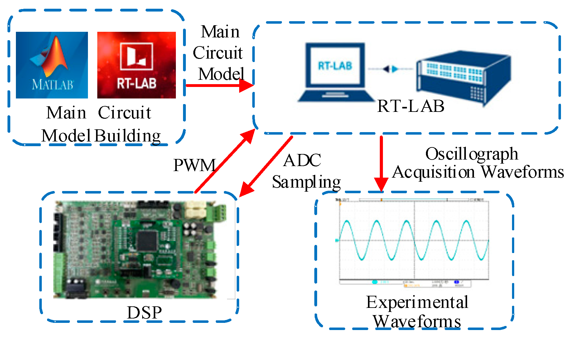
To further validate the effectiveness of the grid voltage feedforward strategy based on multi-objective constraint proposed in this passage, the DSPTMS320F28335 (Texas Instruments, Xi’an, China) is used as the core control, and a semi-physical simulation platform based on RT-LAB is built to verify the effectiveness of the proposed control strategy. This experiment is conducted in a hardware-in-the-loop approach. The experimental platform is shown in Figure 14, and the system parameters are consistent with Table 1.
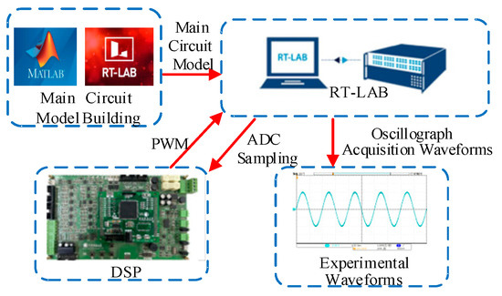
Figure 14.
Hardware-in-the-loop experimental platform.
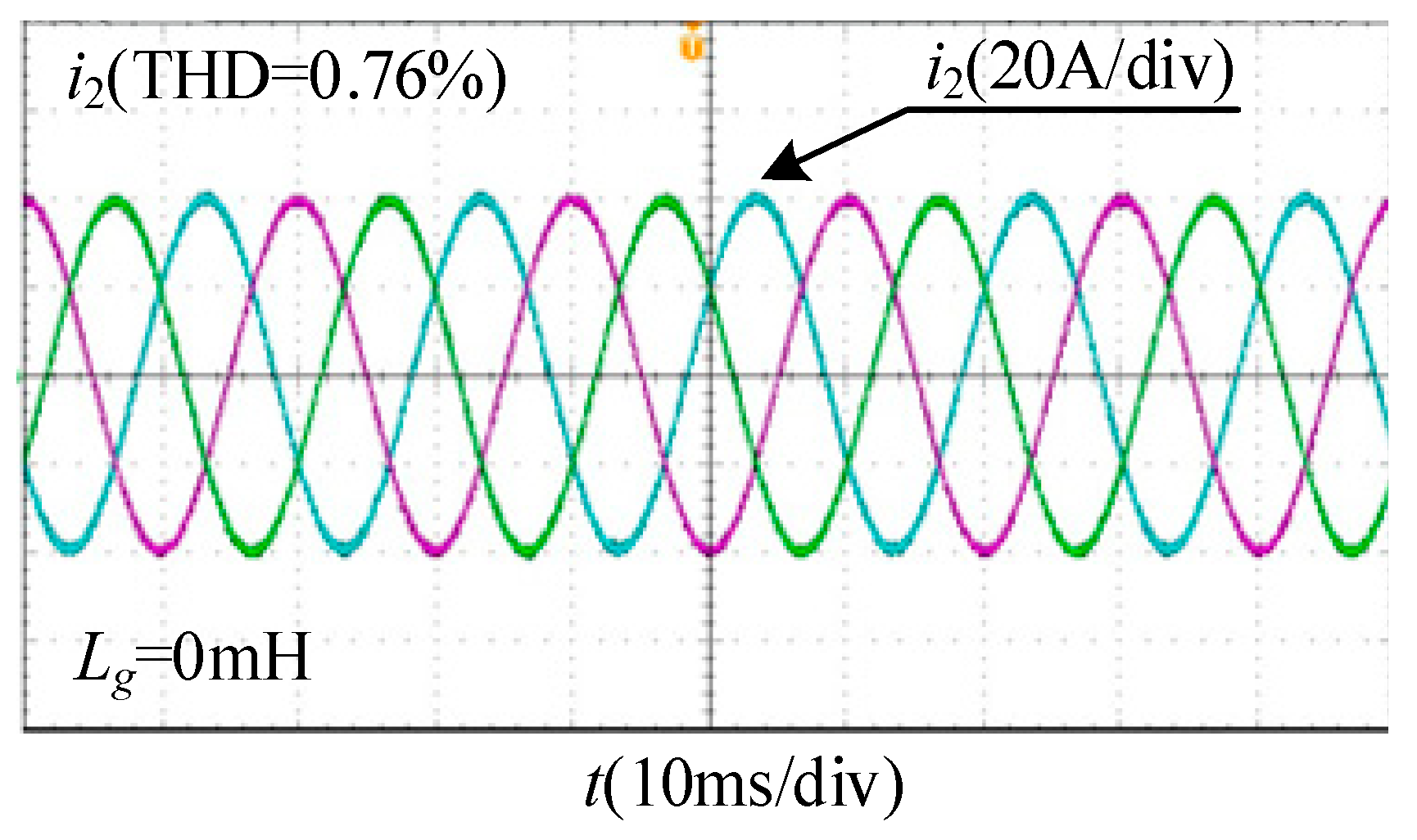
Figure 15 shows the experimental waveform of the grid-connected current of the system without grid voltage feedforward control under strong grid condition. At this time, the grid-connected current waveform remains stable, and the THD of the current is 0.76%, which meets the grid-connected condition.
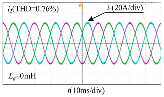
Figure 15.
Hardware-in-the-loop experiment waveform of grid-connected current of the system under strong grid condition without grid voltage feedforward control.
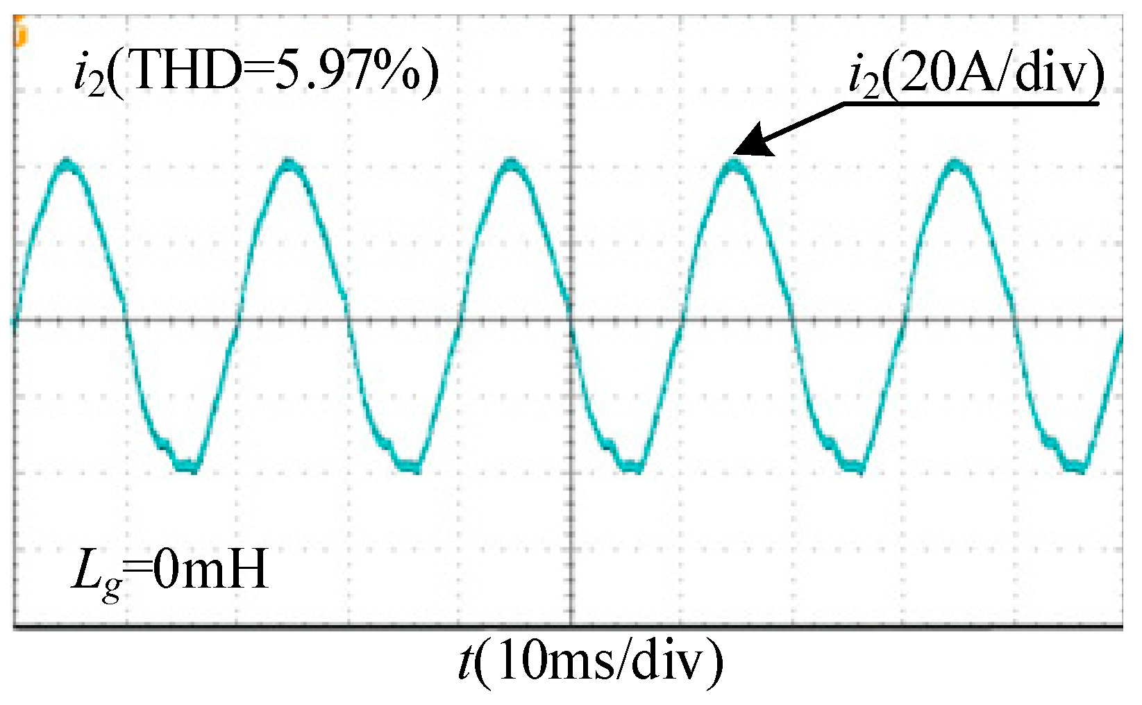
Figure 16 shows the experimental waveforms of the grid-connected current after injecting each 3% of the 5th and 7th harmonics into the grid voltage in the case of a strong grid and without feedforward control of the grid voltage, at which time the grid-connected current undergoes a distortion, and the THD of the current is 5.97%.
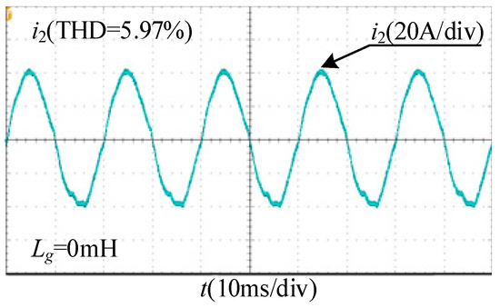
Figure 16.
Hardware-in-the-loop experiment waveform of grid-connected current after harmonic injection.
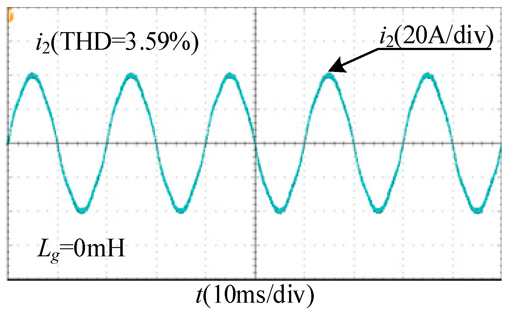
Figure 17 shows the experimental waveform of the grid-connected current with the proportional feedforward control added after injecting grid voltage harmonic. From Figure 18, it can be seen that the added proportional feedforward control can suppress the effect of grid voltage fluctuation on the grid-connected current. The grid-connected current is improved and stabilized. The THD of the current is 3.59%.
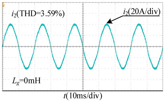
Figure 17.
Hardware-in-the-loop experiment waveform of grid-connected current under proportional feedforward control.
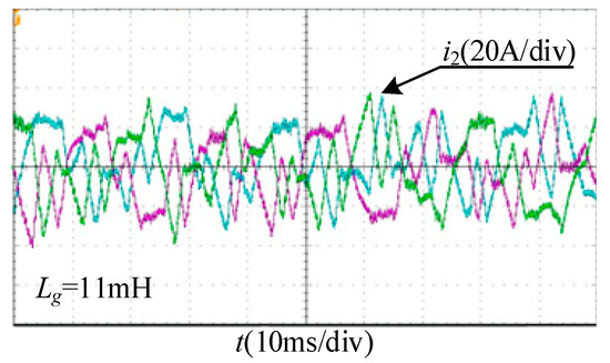
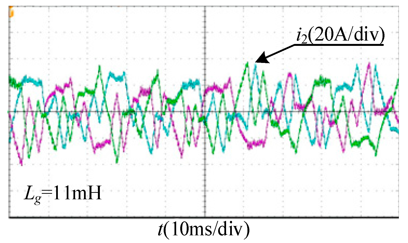
Figure 18.
Hardware-in-the-loop experiment waveform of grid-connected current with proportional feedforward control in weak grid.
Weak grid experiments are performed next, and the following experiment is conducted under a very weak grid condition, SCR = 2, Lg = 11 mH and all are injected with 3% of the 5th and 7th grid voltage harmonic.
Figure 18 shows the experimental waveform of the grid-connected current in weak grid, which only added proportional feedforward control, and it can be seen that the system grid-connected three-phase current occurs serious distortion at this time. The original system will no longer be stable.
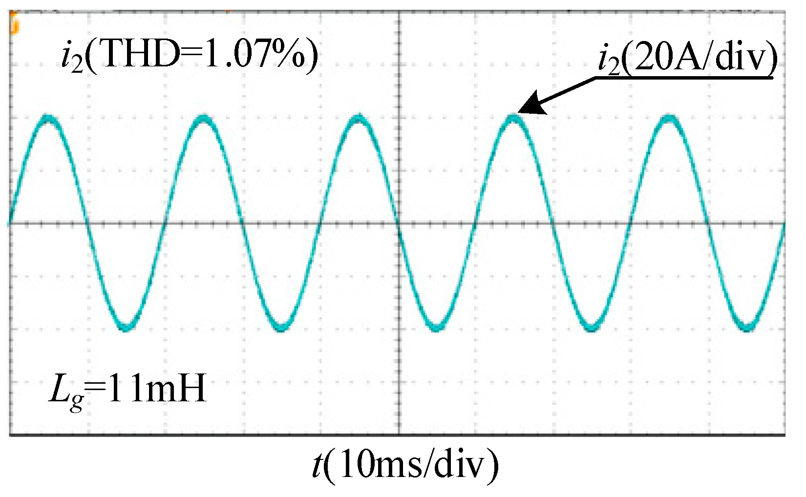
Figure 19 shows the experimental waveform of the grid-connected current for the weak grid case where the proportional feedforward control is replaced by the BPF feedforward control. The introduction of the BPF re-stabilizes the system and the THD of the grid-connected current is 1.07%.
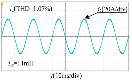
Figure 19.
Hardware-in-the-loop experiment waveform of grid-connected current with BPF feedforward control in weak grid.
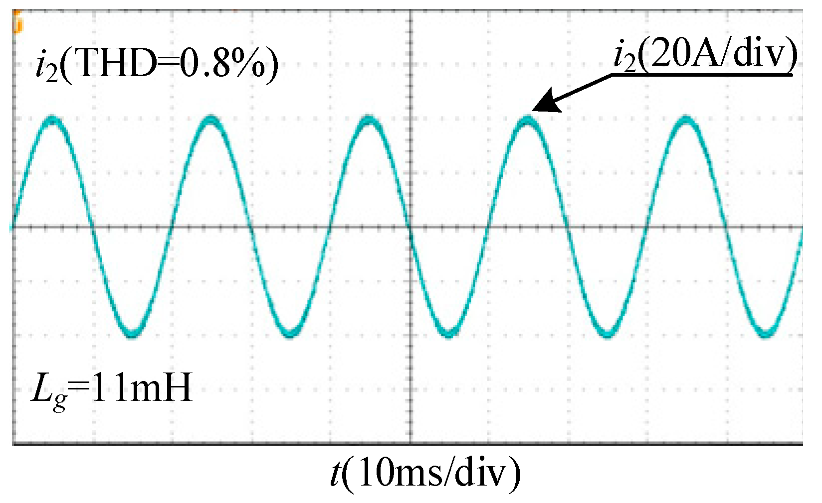
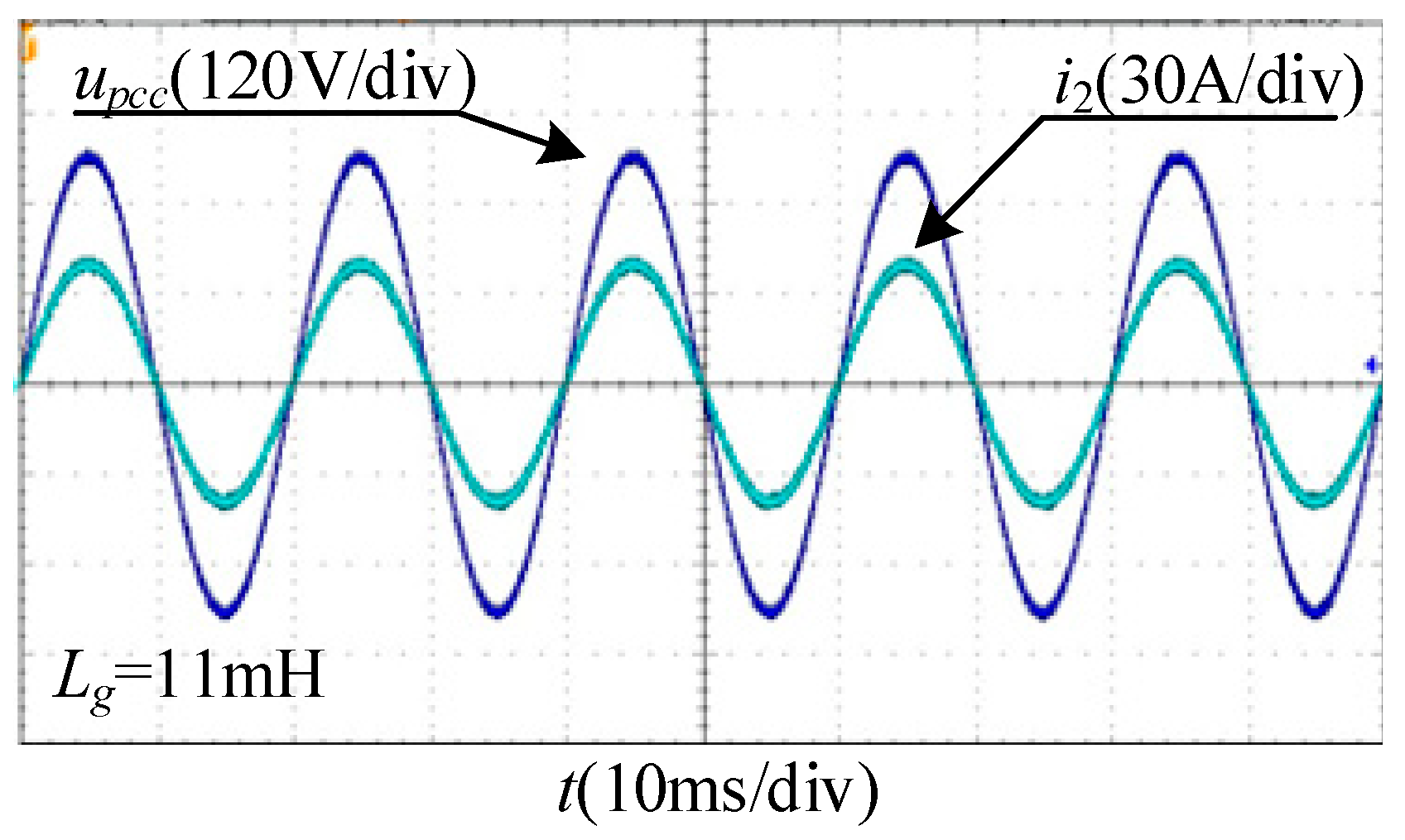
Figure 20 shows the experimental waveform of the grid-connected current under the proposed multi-objective constraint control. From Figure 21, it can be seen that the proposed multi-objective constraint method is able to link directly with the grid-connected requirements to realize the grid connection in the case of very weak grid. Its current THD is 0.8%.
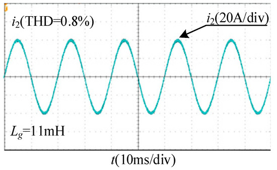
Figure 20.
Hardware-in-the-loop experiment waveform of grid-connected current under multi-objective constraint control in weak grid.
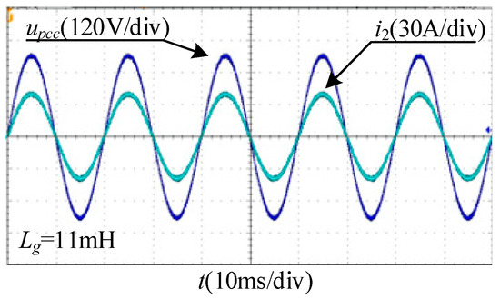
Figure 21.
Hardware-in-the-loop experiment waveform of grid-connected voltage and grid-connected current under multi-objective constraint control in weak grid.
Figure 21 shows the experimental waveform of the system grid-connected current and grid-connected voltage when the multi-objective constraint feedforward control is used. Analyzing Figure 21, it can be seen that based on this control, the unit power factor grid connection can be guaranteed. There is no phase difference in grid-connected voltage and grid-connected current.
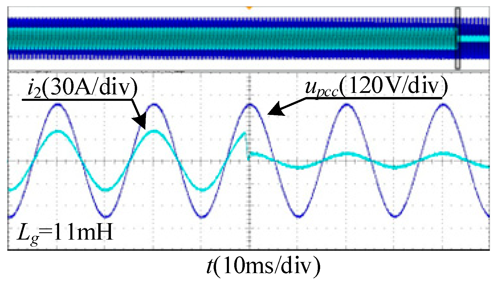
Figure 22 gives the dynamic experimental waveform when the grid-connected current jumps using the multi-objective constraint. The reference current is set to jump from full load to half load. Under this control, the grid-connected current undergoes a short regulation process at the jumping instant and enters into stabilization within half a cycle, which indicates that the system has excellent dynamic performance.
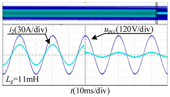
Figure 22.
Hardware-in-the-loop experiment waveform of grid-connected current jump.
Based on the above hardware-in-the-loop experimental results, it is shown that the multi-objective constraint feedforward control strategy proposed in this passage can effectively solve the problems of system robustness degradation and instability in weak grid, and it also solves the problem of designing the BPF parameters redundantly, making the impedance reshaping method more intuitive, and improving the stability of the system in very weak grid.
7. Conclusions
In this paper, a grid voltage feedforward control strategy based on a multi-objective constraint method is proposed as an example for a three-phase LCL grid-connected inverter, and the proposed strategy effectively solves the situation of insufficient system stability margin in the case of a weak grid, and the work of this paper is summarized as follows:
(1) This paper analyzed the mechanisms and feedforward channels that can lead to system destabilization in weak grid. By adding BPF to feedforward control, the role of feedforward control in reducing the effect of grid voltage fluctuation on the grid-connected current was retained.
(2) For the BPF feedforward control used, the parameters design is too redundant and cannot be integrated with the final grid connection requirements. A multi-objective constraint method is proposed to solve this problem. The suggestions are as follows: relying on inverter output impedance stability criterion, considering the improvement of the feedforward channel as a reshaping of the inverter output impedance, detaching from the perspective of filter design, linking the added BPF to the system as a whole, optimizing the variables in the BPF, reshaping of the inverter output impedance, and making the system adapt to more severe conditions.
(3) The multi-objective constraint approach proposed in this paper has a wide range of applications. The multi-objective constraint method can still be used when the improvement for feedforward control is no longer adding filter but other methods. The method can combine the proposed improvements with the grid connection requirements, satisfying actual engineering requirements.
(4) For other feedforward control block diagrams, this study builds on the underlying feedforward control block diagram. Currently, there may be new control block diagrams proposed by scholars that are widely applied. So, for a new control block diagram, the modeling calculations have to be re-conducted. In addition to this, a multi-inverter parallel system will be investigated to verify whether this method is usable or not.
Author Contributions
Conceptualization, S.W. and P.H.; Methodology, K.C.; Software, K.C.; Validation, K.C.; Writing—original draft, K.C. All authors have read and agreed to the published version of the manuscript.
Funding
This research was funded by the Key Research and Development Plan of Shaanxi Province, grant number 2024GX-YBXM-468.
Data Availability Statement
The original contributions presented in the study are included in the article, further inquiries can be directed to the corresponding author.
Conflicts of Interest
The authors declare no conflicts of interest.
References
- Blaabjerg, F.; Teodorescu, R.; Liserre, M.; Timbus, A.V. Overview of Control and Grid Synchronization for Distributed Power Generation Systems. IEEE Trans. Ind. Electron. 2006, 53, 1398–1409. [Google Scholar] [CrossRef]
- Han, Y.; Zhang, K.; Li, H.; Coelho, E.A.A.; Guerrero, J.M. MAS-Based Distributed Coordinated Control and Optimization in Microgrid and Microgrid Clusters: A Comprehensive Overview. IEEE Trans. Power Electron. 2018, 33, 6488–6508. [Google Scholar] [CrossRef]
- Karasala, C.; Lekkala, R.R.; Myneni, H.; Ganjikunta, S.K. PV Grid-Connected Inverter with DC Voltage Regulation in CCM and VCM Operation to Reduce Switching Losses. IEEE Trans. Ind. Electron. 2023, 70, 11262–11275. [Google Scholar] [CrossRef]
- Ferreira, S.C.; Gonzatti, R.B.; Pereira, R.R.; da Silva, C.H.; da Silva, L.E.B.; Lambert-Torres, G. Finite Control Set Model Predictive Control for Dynamic Reactive Power Compensation with Hybrid Active Power Filters. IEEE Trans. Ind. Electron. 2018, 65, 2608–2617. [Google Scholar] [CrossRef]
- Qi, J.; Zhao, W.; Bian, X. Comparative Study of SVC and STATCOM Reactive Power Compensation for Prosumer Microgrids with DFIG-Based Wind Farm Integration. IEEE Access 2020, 8, 209878–209885. [Google Scholar] [CrossRef]
- Wang, X.; Blaabjerg, F.; Loh, P.C. Grid-Current-Feedback Active Damping for LCL Resonance in Grid-Connected Voltage-Source Converters. IEEE Trans. Power Electron. 2016, 31, 213–223. [Google Scholar] [CrossRef]
- Mohamed, Y.A.-R.I. Suppression of Low- and High-Frequency Instabilities and Grid-Induced Disturbances in Distributed Generation Inverters. IEEE Trans. Power Electron. 2011, 26, 3790–3803. [Google Scholar] [CrossRef]
- Zhang, H.; Ruan, X.; Lin, Z.; Wu, L.; Ding, Y.; Guo, Y. Capacitor Voltage Full Feedback Scheme for LCL-Type Grid-Connected Inverter to Suppress Current Distortion Due to Grid Voltage Harmonics. IEEE Trans. Power Electron. 2021, 36, 2996–3006. [Google Scholar] [CrossRef]
- Ma, G.; Xie, C.; Li, C.; Zou, J.; Guerrero, J.M. Passivity-Based Design of Passive Damping for LCL-Type Grid-Connected Inverters to Achieve Full-Frequency Passive Output Admittance. IEEE Trans. Power Electron. 2023, 38, 16048–16060. [Google Scholar] [CrossRef]
- Wu, W.; He, Y.; Tang, T.; Blaabjerg, F. A New Design Method for the Passive Damped LCL and LLCL Filter-Based Single-Phase Grid-Tied Inverter. IEEE Trans. Ind. Electron. 2013, 60, 4339–4350. [Google Scholar] [CrossRef]
- Beres, R.N.; Wang, X.; Blaabjerg, F.; Liserre, M.; Bak, C.L. Optimal Design of High-Order Passive-Damped Filters for Grid-Connected Applications. IEEE Trans. Power Electron. 2016, 31, 2083–2098. [Google Scholar] [CrossRef]
- Rodriguez-Diaz, E.; Freijedo, F.D.; Vasquez, J.C.; Guerrero, J.M. Analysis and Comparison of Notch Filter and Capacitor Voltage Feedforward Active Damping Techniques for LCL Grid-Connected Converters. IEEE Trans. Power Electron. 2019, 34, 3958–3972. [Google Scholar] [CrossRef]
- Zhang, H.; Wang, X.; He, Y.; Pan, D.; Ruan, X. A Compensation Method to Eliminate the Impact of Time Delay on Capacitor-Current Active Damping. IEEE Trans. Ind. Electron. 2022, 69, 7512–7516. [Google Scholar] [CrossRef]
- Zeng, C.; Wang, H.; Li, S.; Miao, H. Grid-Voltage-Feedback Active Damping with Lead Compensation for LCL-Type Inverter Connected to Weak Grid. IEEE Access 2021, 9, 106813–106823. [Google Scholar] [CrossRef]
- Chen, W.; Zhang, Y.; Tu, Y.; Guan, Y.; Shen, K.; Liu, J. Unified Active Damping Strategy Based on Generalized Virtual Impedance in LCL-Type Grid-Connected Inverter. IEEE Trans. Ind. Electron. 2023, 70, 8129–8139. [Google Scholar] [CrossRef]
- Bao, C.; Ruan, X.; Wang, X.; Li, W.; Pan, D.; Weng, K. Step-by-Step Controller Design for LCL-Type Grid-Connected Inverter with Capacitor–Current-Feedback Active-Damping. IEEE Trans. Power Electron. 2014, 29, 1239–1253. [Google Scholar]
- Zhou, X.; Zhou, L.; Chen, Y.; Shuai, Z.; Guerrero, J.M.; Luo, A.; Wu, W.; Yang, L. Robust Grid-Current-Feedback Resonance Suppression Method for LCL-Type Grid-Connected Inverter Connected to Weak Grid. IEEE J. Emerg. Sel. Top. Power Electron. 2018, 6, 2126–2137. [Google Scholar] [CrossRef]
- Wang, X.; Ruan, X.; Liu, S.; Tse, C.K. Full Feedforward of Grid Voltage for Grid-Connected Inverter with LCL Filter to Suppress Current Distortion Due to Grid Voltage Harmonics. IEEE Trans. Power Electron. 2010, 25, 3119–3127. [Google Scholar] [CrossRef]
- Xu, F.; Zhu, M.; Ye, Y. The Stability of LCL-Type Grid-Tied Inverter Based on Repetitive Control and Grid Voltage Feed-Forward. IEEE J. Emerg. Sel. Top. Power Electron. 2023, 11, 1496–1506. [Google Scholar] [CrossRef]
- Wang, X.; Qin, K.; Ruan, X.; Pan, D.; He, Y.; Liu, F. A Robust Grid-Voltage Feedforward Scheme to Improve Adaptability of Grid-Connected Inverter to Weak Grid Condition. IEEE Trans. Power Electron. 2021, 36, 2384–2395. [Google Scholar] [CrossRef]
- Li, M.; Zhang, X.; Zhang, H.; Zhang, H.; Guan, W. An Improved Grid Voltage Feedforward Compensation Scheme of Grid-Connected Inverter in Weak Grid. In Proceedings of the IEEE International Power Electronics and Application Conference and Exposition, Shenzhen, China, 4–7 November 2018; pp. 1–6. [Google Scholar]
- Xu, J.; Xie, S.; Qian, Q.; Zhang, B. Adaptive Feedforward Algorithm Without Grid Impedance Estimation for Inverters to Suppress Grid Current Instabilities and Harmonics Due to Grid Impedance and Grid Voltage Distortion. IEEE Trans. Ind. Electron. 2017, 64, 7574–7586. [Google Scholar] [CrossRef]
- Lin, Z.; Ruan, X.; Wu, L.; Zhang, H.; Li, W. Multi resonant Component-Based Grid-Voltage-Weighted Feedforward Scheme for Grid-Connected Inverter to Suppress the Injected Grid Current Harmonics Under Weak Grid. IEEE Trans. Power Electron. 2020, 35, 9784–9793. [Google Scholar] [CrossRef]
- Wang, C.; Wang, X.; He, Y.; Ruan, X. A Passivity-Based Weighted Proportional-Derivative Feedforward Scheme for Grid-Connected Inverters with Enhanced Harmonic Rejection Ability. IEEE J. Emerg. Sel. Top. Power Electron. 2023, 11, 3656–3668. [Google Scholar] [CrossRef]
- Fang, T.; Liu, H.; Zhang, H.; Liu, C. Robust Technique Using the Optimized Grid Voltage Feedforward to Conquer the Impact Induced by Dual Factors for Grid-Connected Inverter in Weak Grid. IEEE Trans. Ind. Electron. 2024, 71, 7199–7209. [Google Scholar] [CrossRef]
- Wu, X.; Li, X.; Yuan, X.; Geng, Y. Grid Harmonics Suppression Scheme for LCL-Type Grid-Connected Inverters Based on Output Admittance Revision. IEEE Trans. Sustain. Energy 2015, 6, 411–421. [Google Scholar] [CrossRef]
- Sun, J. Impedance-Based Stability Criterion for Grid-Connected Inverters. IEEE Trans. Power Electron. 2011, 26, 3075–3078. [Google Scholar] [CrossRef]
Disclaimer/Publisher’s Note: The statements, opinions and data contained in all publications are solely those of the individual author(s) and contributor(s) and not of MDPI and/or the editor(s). MDPI and/or the editor(s) disclaim responsibility for any injury to people or property resulting from any ideas, methods, instructions or products referred to in the content. |
© 2024 by the authors. Licensee MDPI, Basel, Switzerland. This article is an open access article distributed under the terms and conditions of the Creative Commons Attribution (CC BY) license (https://creativecommons.org/licenses/by/4.0/).

