Article

Wellbore Integrity Analysis of a Deviated Well Section of a CO2 Sequestration Well under Anisotropic Geostress

1
State Key Laboratory of Offshore Oil Exploitation, CNOOC, Beijing 100028, China
2
Bohai Rim Energy Research Institute, Northeast Petroleum University, Qinhuangdao 066004, China
3
College of Civil Engineering & Architecture, Northeast Petroleum University, Daqing 163318, China
4
School of Environmental & Safety Engineering, Liaoning Petrochemical University, Fushun 113001, China
5
PetroChina Daqing Oilfield Production Engineering & Research Institute, Daqing 163453, China
*
Authors to whom correspondence should be addressed.
Energies 2024, 17(13), 3290; https://doi.org/10.3390/en17133290
Submission received: 29 May 2024 / Revised: 28 June 2024 / Accepted: 30 June 2024 / Published: 4 July 2024
(This article belongs to the Topic Advances in Oil and Gas Wellbore Integrity)

Abstract

:
On the basis of “Carbon Peak and Carbon Neutral” goals, carbon sequestration projects are increasing in China. The integrity of cement sheaths, as an important factor affecting carbon sequestration projects, has also received more attention and research. When CO2 is injected into the subsurface from sequestration wells, the cement sheath may mechanically fail due to the pressure accumulated inside the casing, which leads to the sealing of the cement sheath failing. The elasticity and strength parameters of the cement sheath are considered in this paper. The critical bottom-hole injection pressures of inclined well sections under anisotropic formation stresses at different depths were calculated for actual carbon-sealing wells in the X block—the CO2 sequestration target block. The sensitivity factors of the critical bottom-hole injection pressure were also analyzed. It was found that the cement sheath damage criterion was tensile damage. The Young’s modulus and tensile strength of the cement sheath are the main factors affecting the mechanical failure of the cement sheath, with Poisson’s ratio having the second highest influence. An increase in the Young’s modulus, Poisson’s ratio, and tensile strength of the cement sheath can help to improve the mechanical stability of cement sheaths in CO2 sequestration wells. This model can be used for the design and evaluation of cement in carbon sequestration wells.

1. Introduction

With the rapid development in the construction of global carbon sequestration facilities, the carbon sequestration capacity is increasing [1]. Carbon dioxide capture and storage (CCS) in deep geological formations is an effective strategy to mitigate severe climate change. CCS is the process of capturing CO2 from the atmosphere or other carbon sources and injecting it into deep geological formations suitable for storage [2]. Examples include depleted oil, gas reservoirs, and deep saline aquifers. The temperature and pressure of deep saline aquifers generally reach supercritical conditions for CO2, which is sequestered in a supercritical state during its formation and thus permanently isolated from the atmosphere [3].
The integrity of the wellbore is critical in the CO2 storage process. If the integrity of the wellbore is jeopardized, CO2 leakage can be easily caused. The CO2 injected into the saline formation under the action of saline multiphase fluids and the cement sheath undergoes chemical dissolution and leaching reactions, resulting in the corrosion of the cement sheath [4]. This increases the permeability of the cement sheath and reduces the compressive strength of the cement sheath [5]. In addition, the internal pressure of the casing also has an important effect on the failure of the cement sheath. When the casing pressure is high, the casing–cement sheath assembly may become damaged. The cement sheath body may become tensile- or shear-damaged due to reaching the yield limit, which will lead to the failure of the wellbore’s integrity [6].
During long-term CO2 sequestration processes, maintaining the wellbore integrity (including casing, cement sheath, and near-wellbore formation) is important to maintain the normal operation of the sequestered wells [7]. In terms of experimental studies on cement sheath failure, L. Connell et al. [8] investigated cement sheath sealing at the cement–formation interface and derived a relationship between the cement erosion rate and the water flow rate. Agata Lorek et al. [9] experimentally illustrated that cement corrosion is more severe at the cement–formation interface. Wu Zhiqiang et al. [10] concluded that the improvement of cement quality and the increase in the effective sealing length of the cement sheath can effectively enhance the sealing integrity of the cement sheath interface through indoor experiments on hydraulic sealing integrity. In a theoretical study and numerical simulation of cement sheath sealing, Ai et al. [11] evaluated cement sheath stress integrity by using a dynamic stress integrity model of cement sheath while taking into account changes in temperature and formation pore pressure. Yan Tie et al. [12] analyzed the effects of formation parameters and cement sheath parameters on the sealing capacity of the cement sheath and determined the mechanical parameters of the cement sheath under effective CO2 sealing conditions. Song Li et al. [13] used the computational software FLAC to simulate the temperature change, fluid pressure, and solid deformation at the casing–cement sheath–formation interface and determined that no leakage would occur in the CO2 sealing when the internal pressure of the wellbore was between 8 MPa and 750 MPa.
Zheng et al. considered the effects of cement composition [14], casing eccentricity [15], and elliptical geometry [16] on zonal isolation and provided a risk assessment workflow for abandoned wells in any region [17]. In addition, Zheng et al. also studied the influence of the formation creep effect on the integrity of cement sheaths [18]. Artificial neural networks (ANNs) are used to predict the fatigue failure of cement sheaths. A more convenient and accurate model for predicting the fatigue failure of cement sheaths under cyclic pressure and temperature changes was proposed [19,20]. Chen et al. used statistical methods to analyze the accuracy of the proposed concrete strength criteria, providing a reference for the selection of concrete strength criteria under complex stress states [21]. Zhou et al. [22] used a dynamic multiphase flow simulator to evaluate the effectiveness and suitability of using a subsea capping stack to respond to a CO2 well blowout. Gao Deli et al. [23] established a calculation method for the fracture parameters of radial and interfacial cracks in the cement sheath of the wellbore based on the continuous dislocation distribution method and the virtual crack closure technique. It was established that the thermal expansion coefficient of cement has an important influence on the fracture parameters of cracks. The increased temperature difference between the wellbore fluid and the formation will lead to an increased risk of cement sheath interface failure. Li Q et al. [24] established a thermo-hole-elastic coupling model for the rock damage process and investigated the stress state and damage around the wellbore after CO2 injection. Wang Dian et al. [25] established a cement sheath–formation numerical model based on the cohesive unit method and evaluated the influence of the cement slurry system and cement quality on the leakage risk. Li et al. [26] considered an analytical model with anisotropic formation stress and isotropic inner casing pressure.
In most of the above models, isotropic formation stresses are applied on the outer boundary of the cement sheath, and anisotropic formation stresses are not considered. Although Li et al. considered the anisotropic formation stress case, they calculated the cement sheath failure in the straight section. In this paper, the critical bottom-hole injection pressure in the case of cement sheath failure in inclined well sections under anisotropic formation stress is investigated. This can provide a reference for actual production.

2. Analytical Modeling

The computational model in this paper was used to evaluate the integrity of the cement sheath in an inclined section of the well by taking into account the anisotropic formation stresses and the interaction between the cement sheath and the formation. This model can be used to analyze critical bottom-hole injection pressures of cement sheaths before shear or tensile damage occurs. This section describes the derivation of the computational model.

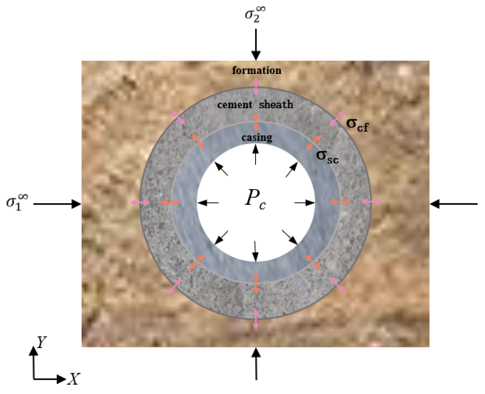
2.1. Calculation of Cement Sheath Stress

After the borehole is cased and cemented, the forces and displacements are continuous at the cement sheath/formation interface, the second interface, assuming that the cement sheath is in close contact with the surrounding formation rock [26]. The far-field principal stress acts in the x-direction as σ 1 and in the y-direction as σ 2 . Under the influence of the cement sheath, the circumferential, radial, and tangential stresses at the cement sheath–formation interface can be calculated from Equations (1)–(3).
σ θ f c = 1 2 ( σ 1 + σ 2 ) 1 + B r C O r 2 1 2 ( σ 1 σ 2 ) × 1 3 C r C O r 4 cos 2 θ
σ r f c = 1 2 ( σ 1 + σ 2 ) 1 B r C O r 2 + 1 2 ( σ 1 σ 2 ) × 1 2 A r C O r 2 3 C r C O r 4 cos 2 θ
τ r θ f c = 1 2 ( σ 1 σ 2 ) 1 + A r C O r 2 + 3 C r C O r 4 sin 2 θ
where A = 2 ( 1     β c f ) β c f k f   +   1 , B = ( k c     1 ) β c f ( k f     1 ) 2 β   +   ( k c     1 ) , C = ( β c f     1 ) β c f k f   +   1 , β c f = E c E f , k c = 3 4 v c , and k f = 3 4 v f .
sqfc is the circumferential stress at the formation/cement sheath interface, MPa; srfc is the radial stress between the formation and the cement sheath, MPa; trqfc is the shear stress between the formation and the cement sheath, MPa; σ 1 is the far-field principal stress in the x-direction, MPa; σ 2 is the far-field principal stress in the y-direction, MPa; rco is the outer radius of the cement sheath, m; r is the radius at any point, m; q is the angle between any point and the x-positive direction; Ec is Young’s modulus of the cement sheath, GPa; Ef is the Young’s modulus of the formation, GPa; vc is the Poisson’s ratio of the cement sheath; vf is the Poisson’s ratio of the formation; and bcf is the stiffness ratio, defined as the ratio of the Young’s modulus of the cement sheath to that of the formation.
The far-field principal stresses, σ 1 and σ 2 , in the x- and y-directions in the above equation are the principal stresses in a straight well section. When the well section is an inclined well, it is necessary to transform the formation stress by coordinate transformation. The transformation equations are shown in Equations (4) and (5).
σ x x σ x y σ x z σ y x σ y y σ y z σ z x σ z y σ z z = L σ H σ h σ v L T
L = cos φ c o s Ω cos φ sin Ω sin φ sin φ cos Ω 0 sin φ c o s Ω sin φ sin Ω cos φ
where j is the well inclination angle, °; W is the azimuth, °; sij (i, j = x, y, z) is the principal stress (i = j) and shear stress (i ≠ j) in different directions after the coordinate transformation, MPa; sH is the horizontal maximum principal stress, MPa; sh is the horizontal minimum principal stress, MPa; and sv is the vertical principal stress, MPa.
Both the casing and the cement sheath alone can be considered a hollow cylinder system. The composite wellbore system consisting of the casing and cement sheath can be regarded as a composite cylinder composed of two different materials. On the inside of the cement sheath; the inner radius of the cement sheath, rci, is equal to the outer radius of the casing, rso. On the outside of the cement sheath, the radial stress, σrco, is equal to the formation’s radial stress, σrfi. The modified lame solution in Equations (6) and (7) can be solved to find the stress state in the composite wellbore system.
σ r w = r c o 2 σ r c o r s i 2 P i r c o 2 r s i 2 + r c o 2 r s i 2 ( P i σ r c o ) r c o 2 r s i 2 r 2 r s i r r c o
σ θ w = ( r c o 2 σ r c o r s i 2 P i ) r c o 2 r s i 2 r c o 2 r s i 2 ( P i σ r c o ) r c o 2 r s i 2 r 2 r s i r r c o
where srw is the radial stress in a composite wellbore system, MPa; rco is the outer radius of the cement sheath, m; srco is the radial stress at the outer edge of the cement sheath, MPa; rsi is the inner radius of the casing, m; Pc is the casing pressure, MPa; and sqw is the circumferential stress in the composite wellbore system, MPa.
As mentioned earlier, it is assumed that the casing and the cement sheath together form a composite cylinder. The cement sheath is firmly bonded to the outside of the casing. The first and second cemented surfaces have an outer casing–inner cement sheath interface bonding stress, σsc, and an outer cement sheath–inner formation interface bonding stress, σcf, respectively (Figure 1). Considering the influence of these two kinds of bonding stresses, the radial and circumferential stresses of the cement sheath can be calculated using Equations (8) and (9).
σ r c s = r c o 2 σ c f r c i 2 σ s c r c o 2 r c i 2 + r c o 2 r c i 2 ( σ s c σ c f ) ( r c o 2 r c i 2 ) r 2
σ θ c s = r c o 2 σ c f r c i 2 σ s c r c o 2 r c i 2 r c o 2 r c i 2 ( σ s c σ c f ) ( r c o 2 r c i 2 ) r 2
where srcs is the radial stress between the cement sheath and the casing affected by the bonding stresses, MPa; scf is the bonding stress between the cement sheath and the formation, MPa; ssc is the bonding stress between the cement sheath and the casing, MPa; rci is the distance of the inside of the cement sheath from the center of the casing, m; and sqcs is the circumferential stress between the cement sheath and the casing affected by the bonding stresses, MPa.
The final stress state of the cement sheath is mainly composed of the following three parts: (1) the radial external stress at the interface of the outer cement sheath and the inner formation produced by the influence of the far-field stress in two directions; (2) the radial external stress at the interface of the outer casing and the inner cement sheath produced by the influence of the pressure of the inner casing; and (3) the initial state of the stress induced by the cement sheath itself under the influence of the bonding stress on the two cemented surfaces. According to the principle of superposition, the sum of the stresses generated by σ 1 , σ 2 , Pi, σsc, and σcf was calculated as in Equations (6)–(9), which led to the total radial stresses, σr, and circumferential stresses, σθ, of the cement sheath. The final stress state of the cement sheath can be expressed by Equations (10) and (11).
σ r = σ r w + σ r c s = r c o 2 σ r c o r s i 2 P i r c o 2 r s i 2 + r c o 2 r s i 2 ( P i σ r c o ) r c o 2 r s i 2 r 2 + r c o 2 σ c f r c i 2 σ s c r c o 2 r c i 2 + r c o 2 r c i 2 σ s c σ c f r c o 2 r c i 2 r 2
σ θ = σ θ w + σ θ c s = ( r c o 2 σ r c o r s i 2 P i ) r c 0 2 r s i 2 r c o 2 r s i 2 ( P i σ r c o ) r c o 2 r s i 2 r 2 + r c o 2 σ c f r c i 2 σ s c r c o 2 r c i 2 r c o 2 r c i 2 σ s c σ c f r c o 2 r c i 2 r 2
where rcirrco.

2.2. Establishment of Failure Criteria

The critical bottom-hole injection pressure, Pimax, was evaluated using tensile and shear damage criteria. As shown in Equation (12), the circumferential stress of the cement sheath must be lower than the tensile strength of the cement sheath when evaluated using the tensile damage criterion.
σ θ < σ t e n s i l e
where sq is the circumferential stress of the cement sheath, MPa, and stensile is the tensile strength of the cement sheath, MPa.
To evaluate the performance of the cement sheath, the failure index FI was defined. The failure index FI for the tensile damage criterion is defined as shown in Equation (13). The judgment criterion is that if FItensile is greater than 1, it means that tensile damage occurs at that position in the cement sheath. Otherwise, the cement sheath will not be considered to have experienced tensile failure.
F I t e n s i l e = σ θ σ t e n s i l e
where FItensile is the failure index for the tensile damage criterion.
The shear damage criterion used in this paper was the Mohr–Coulomb theory, and the shear damage criterion was evaluated as shown in Equation (14).
| σ r | 2 σ cohesion cos φ 1 sin φ + | σ θ | 1 + sin φ 1 sin φ
where scohesion is the cohesion of the cement sheath, MPa, and j is the angle of the internal friction of the cement sheath, °.
The FI of the shear damage is defined as shown in Equation (15). The judgment criterion is that if FIshear is greater than 1, shear damage will occur at that location in the cement sheath. Conversely, the cement sheath will not undergo shear damage if it is less than 1.
F l s h e a r = | σ r | 2 σ c o h e s i o n c o s φ 1     s i n φ + | σ θ | 1   +   s i n φ 1     s i n φ
where FIshear is the failure index for the shear damage criterion.

3. Instance Validation

The X gas field is located in the southwestern part of the Bozhong Depression in the Bohai Bay Basin. It is a dorsal tectonic zone characterized by a ridge in a depression sandwiched between the southwestern sub-depression and the southern sub-depression of the Bohai Depression [27]. The main part of the block has several long-axis backslopes, which are basically divided by near-north–east- and north–east-oriented faults [28]. Block X is influenced by the right-wing strike–slip rupture. The clamping area formed a north–south-oriented tensile stress, which in turn formed an east–west- and north–east-oriented normal fault system [29].
The Guantao Formation in the X gas field is a braided river deposit [30], with a burial depth of 2000 m~2900 m and a thickness of 510 m~650 m in the sand body and a stable distribution and spread throughout the whole area. The CO2 injection wellbore frame is shown in Figure 2. The cement sheath between the production casing and the intermediate casing returns to the top of the reservoir. The upper part of the Guantao Formation is the Minghuazhen Formation, and the longitudinal drilling rate of sandstone in the Minghuazhen Formation is 10%~20%. The spread of mudstone is relatively stable in the whole area, with a thickness of 30 m~40 m. This study mainly focuses on the reservoirs of the Neoproterozoic Guantao reservoir.
The maximum bottom displacement of the CO2 injection well in the X gas field is 2704.37 m. The CO2 storage is planned for 100 years. The planar wave range is 1700 m, which is about 800 m away from the water source well. This CO2 injection well has a large displacement and slope. The well’s parameters are shown in Table 1. The CO2 injection well consists of a straight section and an inclined section. The measured depths of the straight section and inclined section are 775.88 m and 3262.06 m, respectively. The inclined section has an inclination angle of 56 degrees. The true vertical depth of the CO2 injection zone ranges from 2400 m to 2600 m.
Table 2 lists the depth and dimensional information for the tubing and each casing. Table 3 lists the mechanical property information for the cement sheath and the formation. There are no tensile strength, internal friction angle, or cohesion data for the cap shale and reservoir sandstone.
During CO2 injection, when the casing pressure below the packer reaches a critical value, the cement sheath will be damaged and its wellbore integrity will be lost. The critical pressure at this time is called the critical bottom-hole injection pressure. Due to the lack of ground stress data in the CO2 injection well, the vertical principal stress and the horizontal maximum and minimum principal stresses adopted in this paper are the average values of the measured ground stress in the three adjacent wells in the target block, respectively. At 2400 m, 2500 m, and 2600 m, the vertical principal stress values were 49.20 MPa, 51.49 MPa, and 53.79 MPa, respectively. The maximum horizontal principal stress values were 48.42 MPa, 50.32 MPa, and 52.69 MPa, respectively. The minimum horizontal principal stress values were 39.71 MPa, 40.36 MPa, and 42.70 MPa, respectively.
It should be noted that after the conversion of the maximum and minimum principal stresses in the horizontal direction to the maximum and minimum principal stresses in the inclined section, shear stresses are actually generated. When calculating the critical bottom-hole injection pressure in the inclined section, the effect of shear stress is not considered in this paper. The bonding stress between the cement sheath and the formation, σcf, and the bonding stress between the cement sheath and the casing, σsc, were selected according to relevant test data and are, respectively, 0.3 MPa and 0.2 MPa.
In judging the damage of the cement sheath, it is assumed that the shear damage and tensile damage of the cement sheath are independent. That is to say, the tensile damage of the cement sheath is not considered when shear damage occurs, and the shear damage of the cement sheath is not considered when tensile damage occurs. The damage to the cement sheath was determined by which critical value of the shear failure index and tensile failure index was reached first.
Generally speaking, the damage risk of the cement sheath in the reservoir section is higher than that in the cap section, so the sandstone in the reservoir section is chosen for the calculation. As shown in Figure 3, the radial and circumferential stress distributions of the cement sheath at true vertical depths of 2400 m, 2500 m, and 2600 m in the Guantao reservoir show that the radial stress in the y-direction of the cement sheath is obviously larger than that in the x-direction, which is due to the fact that the far-field principal stress in the y-direction obtained by the transformation of the diagonal cross-section, σ 2 , is larger than that in the x-direction by about 5.5 MPa. Relatively, the circumferential stress in the x-direction is larger than that in the y-direction. The maximum values of the radial stress at the three depths are 23.75 MPa, 23.85 MPa, and 25.45 MPa, respectively, and the maximum values of the circumferential stress are 12.05 MPa, 11.50 MPa, and 12.60 MPa, respectively.
From Figure 4, it can be seen that the shear failure indices of the cement sheath at the three depths range from 0.288 to 0.540, which is not enough for shear damage to occur. The tensile failure indices of the inner side of the cement sheath in the x-direction are all very close to 1, which reaches the critical failure state. The critical bottom-hole injection pressures at 2400 m, 2500 m, and 2600 m are 80.37 MPa, 83.57 MPa, and 87.39 MPa, respectively.
For the inclined section of the CO2 injection well in the X gas field, the tensile damage of the cement sheath at the sandstone in the reservoir section occurs before the shear damage under the consideration of the anisotropic formation stress. Therefore, tensile damage can be used as the main damage criterion for this CO2 injection well.
If the inclined well is replaced by a straight well, the critical injection pressures at 2400 m, 2500 m, and 2600 m could be 67.66 MPa, 68.80 MPa, and 72.62 MPa, respectively. Tensile failure also occurs. It can be seen that the critical bottom-hole injection pressure of the vertical well is about 14 MPa lower on average than that of the inclined well. This may be because when calculating the inclined well, the far-field principal stress, σ 2 , in the y-direction is larger than that of σ 1 in the x-direction; therefore, the calculated circumferential stress is smaller, and the critical bottom-hole injection pressure of the inclined well is larger.

4. Results and Discussion

4.1. Effect of Young’s Modulus

Sensitivity analyses were conducted for sandstone at depths of 2400 m, 2500 m, and 2600 m, respectively, so as to evaluate the effect of the Young’s modulus of the cement sheath on the critical bottom-hole injection pressure. Figure 5 shows that the Young’s modulus has a positive effect on the critical bottom-hole injection pressure. For sandstone at a depth of 2600 m, the critical bottom-hole injection pressure increased from 87.39 MPa to 91.26 MPa when the Young’s modulus of the cement sheath increased from 11 GPa to 35 GPa, which is a 4.43% increase in the critical bottom-hole injection pressure. For other depths, the pattern of change between the critical bottom-hole injection pressure and the Young’s modulus of the cement sheath is basically the same as that of sandstone at a depth of 2600 m.
In general, the higher the Young’s modulus of the cement sheath, the more reliable the well. Borehole cement with a high Young’s modulus is preferred for new well construction and design. The Young’s modulus is recommended to be between 20 and 40 GPa.

4.2. Effect of Poisson’s Ratio

Figure 6 shows the effect of Poisson’s ratio on the critical bottom-hole injection pressure. With an increase in Poisson’s ratio, there is a slight increase in the critical bottom-hole injection pressure.
Similarly, for the sandstone at 2600 m, the critical bottom-hole injection pressure increased from 87.39 MPa to 88.66 MPa when Poisson’s ratio for the cement sheath increased from 0.12 to 0.22, and the critical bottom-hole injection pressure increased by 1.45%. For other depths, the pattern of change between the critical bottom-hole injection pressure and Poisson’s ratio for the cement sheath is basically the same as that of sandstone at a depth of 2600 m.
Overall, Poisson’s ratio has a small positive effect on the critical bottom-hole injection pressure. When cementing CO2 sequestration wells, cement with a larger Poisson’s ratio can be prioritized. Poisson’s ratio is recommended to be between 0.15 and 0.25.

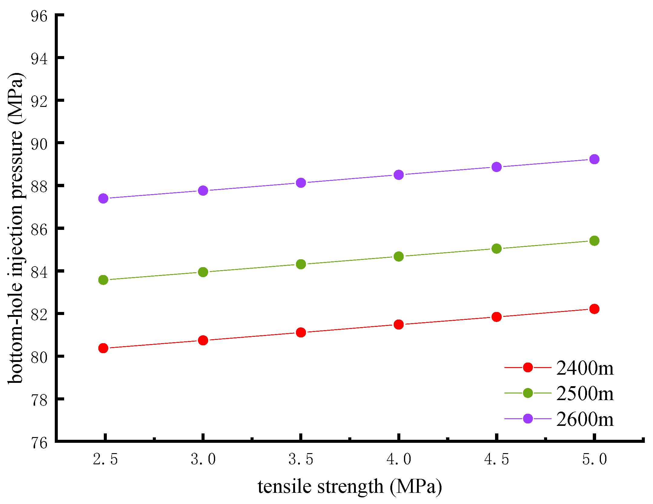
4.3. Effect of Tensile Strength

The tensile strength of the cement sheath is an important factor affecting the tensile damage of the cement sheath. The effect of the cement tensile strength on the critical bottom-hole injection pressure is given in Figure 7. The tensile strength of the cement sheath has a significant positive effect on the critical bottom-hole injection pressure.
The magnitude of the shear failure index is mainly controlled by the internal friction angle, φ, and the cohesion, σcohesion, of the cement sheath. The magnitude of the tensile failure index is mainly controlled by the tensile strength of the cement. In this model, the shear failure index is much smaller than the tensile failure index under the same conditions; the damage to the cement sheath is controlled by the tensile failure criterion. Therefore, in this paper, the influence of the friction angle, φ, and cohesion, σcohesion, of the cement sheath on the critical bottom-hole injection pressure was not analyzed. Only the tensile strength of the cement sheath was considered.
For sandstone at a depth of 2600 m, the critical bottom-hole injection pressure increases from 87.39 MPa to 89.23 MPa when the cement sheath tensile strength increases from 2.49 MPa to 5 MPa, which is a 2.11% increase in the critical bottom-hole injection pressure. For other depths, the pattern of change between the critical bottom-hole injection pressure and cement sheath tensile strength is basically the same as that of sandstone at a depth of 2600 m.

5. Conclusions

This paper provides a calculation scheme for the critical bottom-hole injection pressure in the reservoir of an inclined section of a CO2 sequestration well under an anisotropic stratigraphic stress state. The following conclusions were obtained:
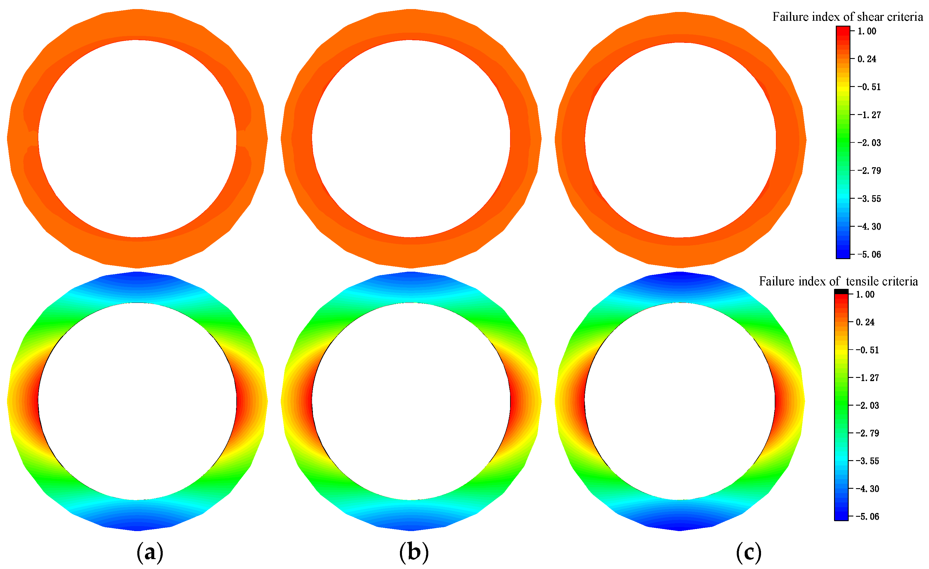
  • The cement sheath in the reservoir section of this work area underwent tensile damage first. The cement sheath may have undergone shear damage during high casing pressure levels. The cement sheath damage criterion of such injection wells is controlled by tensile damage. It is worth noting that the tensile failure of the cement sheath does not occur first in all working conditions. The order of failure will change with different working conditions, such as different formation and cement mechanical parameters and wellbore frames.
  • The Young’s modulus and tensile strength of the cement sheath are the main factors affecting the critical bottom-hole injection pressure. Poisson’s ratio has a smaller effect. An increase in the Young’s modulus, Poisson’s ratio, and tensile strength of the cement sheath will increase the critical bottom-hole injection pressure. The Young’s modulus for cement is recommended to be between 20 and 40 GPa. Poisson’s ratio is recommended to be between 0.15 and 0.25.
  • The deeper the reservoir section, the greater the critical bottom-hole injection pressure.

Author Contributions

Investigation, methodology, validation, and writing—original draft, X.W.; formal analysis, S.J.; data curation and writing—review and editing, S.G.; data curation, L.Z.; supervision, X.Q.; visualization, H.H. All authors have read and agreed to the published version of the manuscript.

Funding

This research received no external funding.

Data Availability Statement

Data are not available as the relevant dataset for oil and gas field companies was used.

Conflicts of Interest

Author Xiabin Wang was employed by the company CNOOC. The remaining authors declare that the research was conducted in the absence of any commercial or financial relationships that could be construed as a potential conflict of interest.

References

  1. Zhang, Z.; Tang, Y.; Wu, Z. Exergy analysis based on CO2 capture and selective exhaust gas recirculation in a natural gas combined cycle power plant. J. South China Norm. Univ. Nat. Sci. Ed. 2023, 55, 1–8. [Google Scholar] [CrossRef]
  2. Vafaie, A.; Cama, J.; Soler, J.M.; Kivi, I.R.; Vilarrasa, V. Chemo-hydro-mechanical effects of CO2 injection on reservoir and seal rocks: A review on laboratory experiments. Renew. Sustain. Energy Rev. 2023, 178, 113270. [Google Scholar] [CrossRef]
  3. Chaparro, M.C.; Klose, T.; Hirsch, A.; Schilling, F.; Butscher, C.; Blum, P. Modelling of wellbore cement alteration due to CO2-rich brine interaction in a large-scale autoclave experiment. Int. J. Greenh. Gas Control 2021, 110, 103428. [Google Scholar] [CrossRef]
  4. Zhang, Z.; Bai, M.; Chen, Q. Influencing factors of corrosion behavior of carbon dioxide storage wellbore. Corros. Prot. 2021, 42, 54–57+61. [Google Scholar] [CrossRef]
  5. Zhang, J.; Xu, M.; Zhu, J.; Wang, G.; Ma, S. Corrosion of oilwell cement by carbon dioxide. J. Chin. Ceram. Soc. 2007, 12, 1651–1656. [Google Scholar] [CrossRef]
  6. Guan, J.; Liao, H.; Lin, Z.; Xie, S.; Zhao, X. Test device for evaluating cement sheath seal integrity under cyclic loading. China Pet. Mach. 2021, 45, 48–53. [Google Scholar] [CrossRef]
  7. Shi, Y.; Guan, Z.; Xi, C.; Miao, Z.; Fu, C. An analytical method for the calculation of allowable internal casing pressure based on the cement sheath integrity analysis. Nat. Gas Ind. 2017, 37, 89–93. [Google Scholar] [CrossRef]
  8. Connell, L.; Down, D.; Lu, M.; Hay, D.; Heryanto, D. An investigation into the integrity of wellbore cement in CO2 storage wells: Core flooding experiments and simulations. Int. J. Greenh. Gas Control 2015, 37, 424–440. [Google Scholar] [CrossRef]
  9. Lorek, A.; Labus, M.; Bujok, P. Wellbore cement degradation in contact zone with formation rock. Environ. Earth Sci. 2016, 75, 499. [Google Scholar] [CrossRef]
  10. Wu, Z.; Yue, J.; Li, Q.; Cao, Y.; Geng, Y.; Liu, S. Experimental study on the hydraulic seal integrity evaluation of casing-cement sheath bonding interface. China Offshore Oil Gas 2018, 30, 129–134. [Google Scholar]
  11. Ai, C.; Li, J.; Li, Z.; Zhang, Z.; Chen, D. Research on cement sheath stress integrity of CO2 buried well in the process of injection. Sci. Technol. Eng. 2013, 13, 2057–2061. [Google Scholar] [CrossRef]
  12. Yan, T.; Li, Y.; Li, J.; Feng, F.; Bai, M. The study on cement sheath sealing effect and its performance parameters of CO2 buried well. China Sci. Technol. Eng. 2014, 14, 25–29. [Google Scholar] [CrossRef]
  13. Song, L.; Tan, Y. A two-dimensional model analysis of casing-cement-strata in geological storage of CO2. Chin. J. Appl. Mech. 2015, 32, 288–293+356. [Google Scholar]
  14. Zheng, D. Geological Analysis and Cement Composition for Improving Zonal Isolation. Ph.D. Thesis, The University of Tulsa, Tulsa, OK, USA, 2023. [Google Scholar]
  15. Zheng, D.; Ozbayoglu, E.; Baldino, S.; Miska, S.; Liu, Y. The influence of casing eccentricity on zonal isolation. In Proceedings of the ARMA 23241 at the 57th US Rock Mechanics/Geomechanics Symposium, Atlanta, GA, USA, 25–28 June 2023. [Google Scholar]
  16. Zheng, D.; Miska, Z.; Ozbayoglu, E.; Zhang, Y. The influence of elliptical-geometry wellbore on zonal isolation. In Proceedings of the Paper Presented at the 56th U.S. Rock Mechanics/Geomechanics Symposium, Santa Fe, NM, USA, 26 June 2022. [Google Scholar] [CrossRef]
  17. Zheng, D.; Turhan, C.; Wang, N.; Ashok, P.; van Oort, E. Prioritizing wells for repurposing or permanent abandonment based on generalized well integrity risk analysis. In Proceedings of the SPE/IADC Drilling Conference and Exhibition, Galveston, TX, USA, 27 February 2024; p. D021S018R001. [Google Scholar]
  18. Zheng, D.; Miska, S.; Ozbayoglu, E. The influence of formation creeping on wellbore integrity. In Proceedings of the Paper presented at the SPE 2021 Symposium Compilation, Virtual, 26 November 2021. [Google Scholar] [CrossRef]
  19. Zheng, D.; Ozbayoglu, E.; Miska, S.; Liu, Y. Cement sheath fatigue failure prediction by ANN-based model. In Proceedings of the Paper Presented at the Offshore Technology Conference, Houston, TX, USA, 2–5 May 2022. [Google Scholar] [CrossRef]
  20. Zheng, D.; Ozbayoglu, E.; Miska, S.; Liu, Y. Cement sheath fatigue failure prediction by support vector machine based model. In Proceedings of the Paper Presented at the SPE Eastern Regional Meeting, Wheeling, WV, USA, 18–20 October 2022. [Google Scholar] [CrossRef]
  21. Chen, X.; Zheng, D.; Wu, X.; Li, C. A review of three common concrete multiaxial strength criteria from 2010 to 2020. Arch. Computat. Methods Eng. 2023, 30, 811–829. [Google Scholar] [CrossRef]
  22. Zhou, L.; Upchurch, E.R.; Liu, Y.; Anfinsen, B.; Hashemian, Y.; Zhao, G. Evaluating subsea capping stack usage for CO2 blowouts. In Proceedings of the Paper Presented at the Offshore Technology Conference, Houston, TX, USA, 6–9 May 2024. [Google Scholar] [CrossRef]
  23. Gao, D.; Dou, H.; Dong, X. Research progress in wellbore cement sheath integrity under conditions of CO2 injection and storage. J. Yan’an Univ. Nat. Sci. Ed. 2022, 41, 1–9+17. [Google Scholar]
  24. Li, Q.; Jing, M. Thermo-poroelastic coupling analysis of rock damage around wellbore due to CO2 injection. Chin. J. Rock Mech. Eng. 2013, 32, 2205–2213. [Google Scholar]
  25. Wang, D.; Li, J.; Liu, P.; Liu, X.; Lian, W.; Lu, Z. Simulation study of sealing integrity in abandoned wells within CO2 sequestration block. Drill. Fluid Complet. Fluid 2023, 40, 384–390. [Google Scholar] [CrossRef]
  26. Li, B.; Guo, B.; Li, H.; Shi, Y. An analytical solution to simulate the effect of cement/formation stiffness on well integrity evaluation in carbon sequestration projects. J. Nat. Gas Sci. Eng. 2015, 27, 1092–1099. [Google Scholar] [CrossRef]
  27. Zhang, G.; Cheng, Q.; Zhang, L.; Liu, W.; Zhao, Y.; Wu, H.; Shen, C. Calculation of 3D reservoir rock mechanical parameters of metamorphic rock reservoirs in the Bozhong 19-6 gas field of the Bohai Bay Basin and their significance. Earth Sci. 2018. [Google Scholar]
  28. Zhao, T.; Wang, F.; Peng, J.; Wang, B. Influence of CO2 injection on phase behavior of oil and gas reservoirs and analysis of gas condensate reservoir genesis: A case study of BZ19-6 gas condensate reservoir. China Offshore Oil Gas 2023, 35, 24–34. [Google Scholar] [CrossRef]
  29. Yang, X.; Liu, C.; Wang, F.; Li, G.; Feng, D.; Yang, T.; He, Z.; Su, J. Distribution and origin of overpressure in the Paleogene Dongying Formation in the southwestern sub-sag, Bozhong Sag, Bohai Bay Basin. Oil Gas Geol. 2024, 45, 96–112. [Google Scholar]
  30. Li, X.; Qin, R. Method of fracture characterization and productivity prediction of 19-6 buried-hill fractured reservoirs, Bohai Bay Basin. Earth Sci. 2023, 48, 475–487. [Google Scholar]
Figure 1. Bonding stress state of a composite wellbore system.
Energies 17 03290 g001
Figure 2. CO2 injection wellbore frame.
Energies 17 03290 g002
Figure 3. Radial and tangential stress distributions of cement sheath at different vertical depths: (a) 2400 m; (b) 2500 m; and (c) 2600 m.
Energies 17 03290 g003
Figure 4. Distribution of failure index for shear and tensile criteria for cement sheath at different vertical depths: (a) 2400 m; (b) 2500 m; and (c) 2600 m.
Energies 17 03290 g004
Figure 5. Effect of Young’s modulus on critical bottom-hole injection pressure.
Energies 17 03290 g005
Figure 6. Influence of Poisson’s ratio on critical bottom-hole injection pressure.
Energies 17 03290 g006
Figure 7. Influence of the tensile strength of the cement sheath on the critical bottom-hole injection pressure.
Energies 17 03290 g007
Table 1. CO2 injection well’s wellbore parameters.
TypeMeasured
Depth/m
Inclination Angle/°Vertical Depth/mBottom Hole
Displacement/m
Target
Horizon
CO2
injection well
4037.945626002704.37Guantao
formation
Table 2. CO2 injection well casing’s outer diameter and measured depth.
TypeOuter Diameter
/mm
Wall Thickness
/mm
Conductor609.6011.13
Surface casing339.738.38
Intermediate casing244.487.92
Production casing177.805.87
Tubing101.605.74
Table 3. Mechanical properties of cement and formation rock.
TypeYoung’s
Modulus/GPa
Poisson
Ratio
Tensile Strength
/MPa
Internal
Frictional
Angle/°
Cohesion
/MPa
Cement110.122.4931.679.16
Cap rock shale400.15
Reservoir sandstone230.29
Disclaimer/Publisher’s Note: The statements, opinions and data contained in all publications are solely those of the individual author(s) and contributor(s) and not of MDPI and/or the editor(s). MDPI and/or the editor(s) disclaim responsibility for any injury to people or property resulting from any ideas, methods, instructions or products referred to in the content.

