Article

Simulation of the Static Sealing Performance of Rubber Packer Cylinders in a Supercritical–CO2 Environment

1
Daqing Oilfield Production Technology Institute, Daqing Oilfield Co., Ltd., Daqing 163453, China
2
Heilongjiang Provincial Key Laboratory of Oil and Gas Reservoir Stimulation, Daqing 163453, China
3
Research Institute of Petroleum Exploration and Development, PetroChina, Beijing 100083, China
4
College of New Energy and Materials, China University of Petroleum–Beijing, Beijing 102249, China
*
Authors to whom correspondence should be addressed.
Energies 2024, 17(13), 3305; https://doi.org/10.3390/en17133305
Submission received: 20 May 2024 / Revised: 1 July 2024 / Accepted: 3 July 2024 / Published: 5 July 2024
(This article belongs to the Special Issue Development of Unconventional Oil and Gas Fields)

Abstract

:
The aim of this study was to solve the problems associated with the sealing and tearing failure of rubber packer cylinders during CO2 downhole injection. Using Comsol Multiphysics 6.0 software, a rubber cylinder model in a supercritical CO2 (SC–CO2) environment was established. The thermal analogy method was used to simulate the CO2 diffusion and rubber cylinder swelling process. We analyzed the deformation and stress of the rubber cylinder that was caused by temperature and pressure, with CO2 as the swelling agent. The results show that in the SC–CO2 environment, under the influence of CO2 diffusion and the consequent swelling, the rubber cylinder body is prone to large deformations, and the maximum shear stress is significantly increased, leading to the shear failure of the rubber cylinder. Reducing the initial seating pressure can alleviate the impact of deformation, whereas reducing the maximum contact pressure can cause the rubber cylinder to lose its seal. We also analyzed the influence of various factors on the maximum contact stress of the rubber cylinder, providing a theoretical basis and technical support for improving the sealing performance of rubber packer cylinders in an SC–CO2 environment.

1. Introduction

At present, carbon capture, utilization, and storage (CCUS) is an important technology used to achieve large–scale carbon reduction. In the field of oil development, CO2 flooding technology, as an effective means by which to improve oil recovery, not only conforms to the concept of effective CCUS, but also utilizes the unique advantages of CO2 during oil recovery enhancement, also known as tertiary recovery [1,2,3]. Supercritical CO2 (SC–CO2) can effectively reduce the residual oil saturation of the reservoir by reducing the interfacial tension between oil and water and the extraction effect, maximizing carbon storage while improving the oil displacement efficiency [4,5,6,7,8,9,10].
The downhole environment of the CO2 injection well is different from conventional injection environments, such as waterflooding. When the temperature exceeds 304.14 K and the pressure exceeds 7.2 MPa, CO2 is converted into a supercritical state with a density close to that of a liquid and a viscosity close to that of a gas, and its diffusion ability is further enhanced. The packer is one of the core tools used for CO2 layered injection. However, with the increase in injection time and temperature, SC–CO2 molecules are more likely to diffuse into the rubber matrix, causing the swelling of the rubber cylinder and further expanding its deformation, which may lead to tearing failure in extreme cases [11,12,13,14,15,16,17,18,19]. There have only been a few studies on the influence of CO2 diffusion and the consequent rubber swelling on the sealing performance of rubber packer cylinders, and there is also a lack of appropriate numerical simulation means for the swelling effect. In this study, simulation software was used to establish a rubber packer cylinder model in the SC–CO2 environment. Based on the thermal analogy method, the gas diffusion and rubber cylinder swelling process was simulated to analyze the deformation and stress of the rubber cylinder caused by temperature and pressure, with CO2 as the swelling agent, and the influence of various factors on the maximum contact stress between the rubber cylinder and the inner wall of the casing was analyzed. This study provides a theoretical basis and technical support for improving the sealing performance of rubber packer cylinders in an SC–CO2 environment.

2. Theoretical Calculation of the Mechanical Properties of the Rubber Cylinder

At present, fluororubber, nitrile rubber, and hydrogenated nitrile rubber are mainly used to manufacture rubber packer cylinders [20]. In this section, using the large deformation property of rubber and the elastic mechanics theory, the stress situation of the rubber cylinder is investigated. To ensure the convergence of the calculation, the absolute volume of the rubber cylinder is treated as incompressible when it does not exceed its elastic limit. The radial and circumferential deformations after the contact between the rubber cylinder and the casing are ignored [21,22,23,24,25,26]. Poisson’s ratio μ of rubber is close to Poisson’s ratio of a liquid, i.e., 0.5, so rubber can be regarded as a material with an approximately incompressible volume, which reflects incompressibility. The material of the casing is metal, and its elastic modulus is much greater than that of rubber. It can be considered that the radial and circumferential deformations of the casing caused by the compression stress generated by rubber deformation are negligible, so the above effects are ignored in the simulation process. The von Mises stress follows the fourth strength theory of material mechanics, which represents the strength at which a material may undergo plastic deformation under complex stress conditions. It is widely used in the field of engineering, especially in material strength analysis, structural design, and finite element analysis. Due to the fact that rubber is a superelastic material, current research on rubber generally adopts the Mooney–Rivlin superelastic material model and applies the fourth strength theory to verify the strength of the rubber. The Mooney–Rivlin two–parameter model was selected as the constitutive model of the rubber cylinder, and the contact pressure between the rubber cylinder and the casing after seating was calculated using the constitutive model [27].
The Mooney–Rivlin two–parameter model is expressed as follows:
W siso = C 10 ( I ¯ 1 3 ) + C 01 ( I ¯ 2 3 ) ,
where W siso is the strain energy density (J); C 10 and C 01 are material constants; I ¯ 1 is the first–order strain invariant; and I ¯ 2 is the second–order strain invariant.
The elastic modulus and shear modulus of rubber are expressed in Equations (2) and (3), respectively:
E = 6 ( C 10 + C 01 ) ,
G = 2 ( C 10 + C 01 ) ,
where E is the elastic modulus (MPa) and G is the shear modulus (MPa).
Regardless of the friction between the rubber cylinder, the casing, and the central pipe, the additional contact pressure generated on the inner wall of the casing caused by the differential pressure between the top and the bottom during the working process can be calculated using Equation (4):
2 π H 1 R t τ r z = Δ P π R t 2 Δ P π R m 2 ,
where H 1 is the axial length of the rubber cylinder under the working conditions (m); R t is the inner radius of the casing (m); R m is the radius of the metal spacer ring (m); τ r z is the shear stress on the contact surface between the rubber cylinder and the casing wall (MPa); and Δ P is the working pressure difference (MPa).
For incompressible materials, the relationship between the micro–element shear stress and the axial stress can be expressed as follows:
σ z z + τ r z r + τ z θ θ = 0
where σ z is the axial length of the rubber cylinder under the working conditions (m), and τ r z is the shear stress on the contact surface between the rubber cylinder and the casing wall (MPa).
The strain of the rubber cylinder can be expressed as follows:
{ ε r = ε θ = 0 τ z θ = τ r θ = 0 ,
According to Equations (4)–(6), the following equations can be derived:
σ z = Δ P 2 ( R t 2 + R m 2 R t 2 ) ,
σ r = μ 1 μ σ z ,
where σ z is the axial length of the rubber cylinder under the working conditions (m); Δ P is the working pressure difference (MPa); R t is the inner radius of the casing (m); R m is the radius of the metal spacer ring (m); and μ is Poisson’s ratio.

3. Establishment of Finite Element Model of Rubber Packer Cylinder

3.1. Geometric Model Establishment and Mesh Generation

We referred to the conventional rubber cylinder that supports a Y341–114 packer for the overall dimensions of the rubber packer cylinder, with an inner diameter of 73 mm and an outer diameter of 114 mm. Forty–degree chamfers were added outside the upper and lower rubber cylinders. The inner diameter of the metal spacer ring of the packer is 73 mm, and the outer diameter is 116 mm. The outer diameter of the central pipe is 73 mm, and the inner diameter of the casing is 121.4 mm. Considering the structural characteristics of the assembly model and reducing the computational intensity, we selected a two–dimensional axisymmetric model in the dimension of the simulation space and established the section geometric model, as shown in Figure 1. To solve the physical field, the ‘solid mechanics’ solution module was selected. To solve the stress relationship of each part in the seating process, each imported part was used to form an assembly. ‘Free triangular mesh’ was selected for mesh division, with a maximum cell size of 2 mm, a minimum cell size of 0.004 mm, a maximum cell growth rate of 1.2, a curvature factor of 0.2, and a narrow area resolution of 1. The total number of mesh cells was 8150, and the average element quality was 0.935. The finite element model and mesh division are shown in Figure 1.

3.2. Setting the Material Properties

Hydrogenated nitrile rubber was selected as the rubber cylinder material. Compared with fluororubber, hydrogenated nitrile rubber has better heat resistance, oxygen aging resistance, and chemical resistance; it is a common material for rubber packer cylinders. The Mooney–Rivlin model has two constants, C10 and C01, representing the linear elastic behavior and nonlinear elastic behavior of the material, respectively. C10 can be used to describe the stiffness of materials, while C01 describes the nonlinear characteristics of materials. The rubber cylinder material model was set as a hyper–elastic material. C10 and C01 in the Mooney–Rivlin model are closely related to the ambient temperature; therefore, different C10 and C01 values were set for the simulation model at different temperatures, as shown in Table 1. The rubber density was set as 1300 kg/m3. The material model of the central pipe and metal spacer ring was set as a linear elastic material, and the material type was set as 3Cr13. The casing material was set as 42MnMo7.

3.3. Boundary Condition Settings

When seated to the casing, the rubber cylinder comes into contact with the central pipe, metal spacer ring, and the inner wall of the casing. Therefore, 12 contact pairs were set, namely the rubber cylinder and the central pipe, the rubber cylinder and the upper metal spacer ring, the rubber cylinder and the lower metal spacer ring, and the rubber cylinder and the inner wall of the casing. All contact pairs were set to use the Coulomb friction model, with a friction coefficient of 0.3. The contact method was set as a penalty function, and the penalty factor was controlled using the built–in program of the software. Given that the central pipe and the lowest metal spacer ring do not move during the entire seating process, they were set as fixed constraints. Point constraints were set at the upper and lower boundaries of the casing, and the contact surfaces between the remaining metal spacer rings and rubber cylinder were supported by virtual springs to ensure the convergence of the calculation process. The specified displacement was set on the uppermost metal spacer ring, and the displacement parameter could be set through a function to gradually add the displacement.

3.4. Finite Element Model Setup of Rubber Swelling Process with CO2 as Swelling Agent

At present, no relevant calculation model for the rubber swelling process with CO2 as the swelling agent has been established. We referred to the finite element method for rubber expansion with hydrogen absorption, ignored the CO2 diffusion caused by stress or other factors, and only considered the effect of the concentration gradient on CO2 diffusion in rubber. Comparing this diffusion process to the heat transfer process of heat conduction in a solid, we replaced the CO2 concentration field in rubber with the temperature field, compared the rubber swelling caused by CO2 diffusion to the thermal expansion of the object caused by the heat transfer process, established a finite element model of heat conduction, and then calculated the stress and strain of the rubber cylinder caused by CO2 diffusion through a thermal–mechanical coupling method.
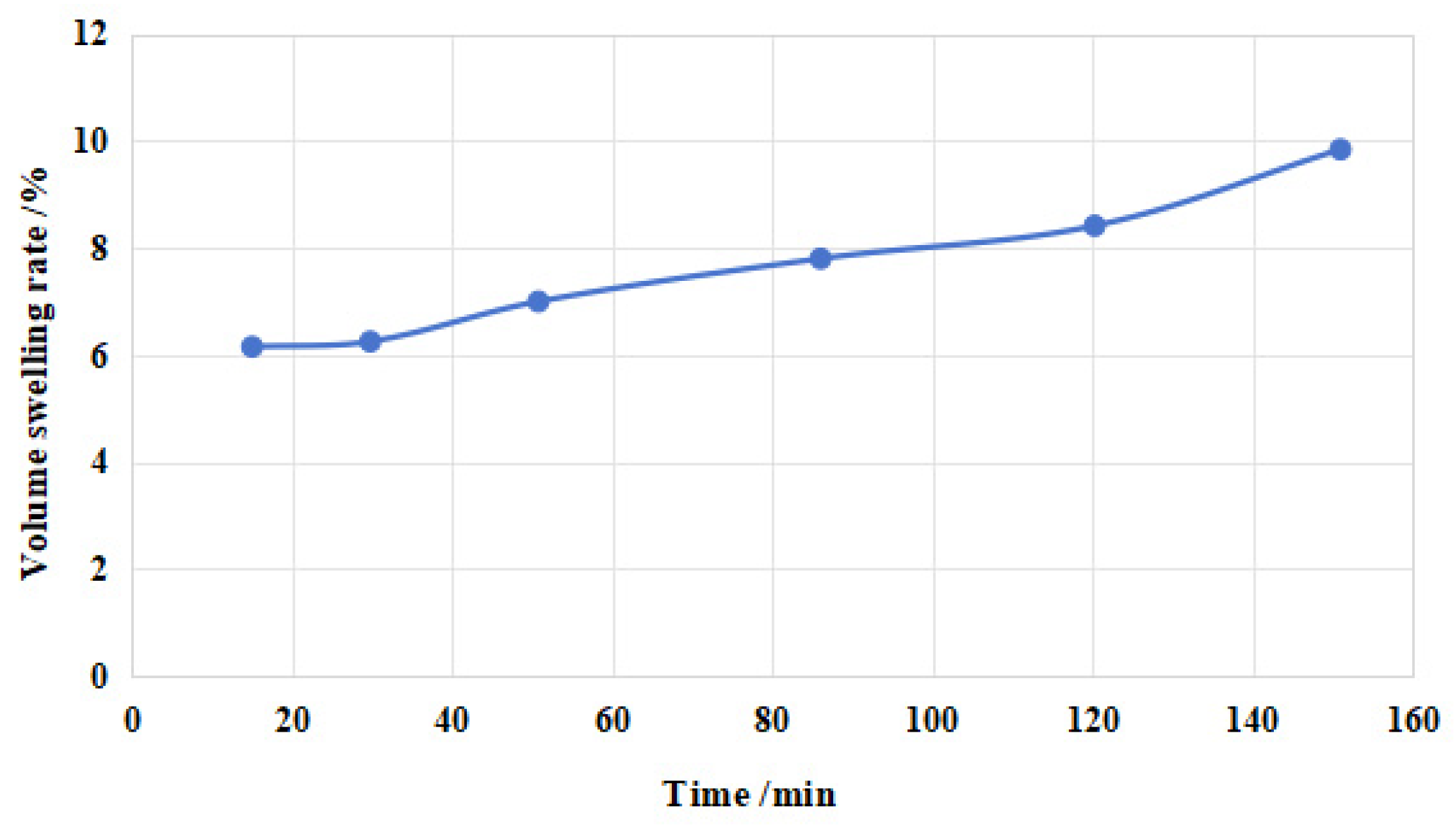
A ‘thermal expansion’ physical reaction interface under the hyper–elastic material node was added, the volume reference temperature was defined as 293.15 K, and the thermal expansion coefficient was set as a tangent coefficient. During the heat transfer calculation, the SC–CO2 concentration at the boundary of the rubber cylinder where there was contact with SC–CO2 was set as saturated, and the boundary temperature was set as 493.15 K, according to a temperature gradient of 276.65 K/100 m. The SC–CO2 concentration at the boundary of the rubber cylinder where there was contact with the central tube was set as 0, and the initial boundary temperature was set as the volume reference temperature. The thermal expansion generated on the rubber cylinder after achieving the steady–state temperature field was obtained through simulation of the heat transfer process; thus, each mechanical parameter of the CO2 diffusion and rubber swelling process could be calculated [29]. As shown in Figure 2, through indoor tests, reference [19] determined the rules of hydrogenated nitrile rubber swelling under high temperature and pressure with CO2 diffusion, and we therefore set the tangent thermal expansion coefficient of the rubber material as 0.002/K.

4. Analysis of the Simulation Results

4.1. Effect of Seating Distance on Sealing Performance of Rubber Cylinder

Before seating, a reasonable seating distance should be determined for the rubber cylinder to ensure effective sealing of the tubing–casing annulus. A lower seating distance could lead to the incomplete seating of the rubber cylinder, resulting in a reduction in the contact area and contact pressure between the rubber cylinder and the inner wall of the casing. A longer seating distance tends to destroy the rubber cylinder and reduce the sealing reliability. For the simulation model, the seating distances were set as 25 mm, 30 mm, and 40 mm. Figure 3 shows the von Mises stress nephogram of the rubber cylinder corresponding to three seating distances at normal temperature without considering the influence of SC–CO2 diffusion and working pressure difference.
The figure shows that with an increase in the seating distance, the shape of the rubber cylinder exhibited large deformations, and the increment of the deformation and stress decreased from top to bottom. With the seating distance being 25 mm, the rubber cylinder had not been fully compressed. With the seating distance being 30 mm, the von Mises stress in the rubber cylinder began to concentrate, and the deformation was intensified. With the seating distance being 40 mm, the von Mises stress concentration further increased, and the rubber cylinder had completely filled the enclosed space.
Figure 4 shows the contact pressure between the rubber cylinder and the inner wall of the casing at three different seating distances. The figure shows that with the seating distance being 25 mm, the top rubber cylinder and the bottom rubber cylinder first came into contact with the inner wall of the casing and produced extrusion. With an increase in the seating distance, the contact pressure of the middle rubber cylinder increased faster than that of the lower rubber cylinder. The seating mode of the conventional packer was unidirectional compression at the bottom spacer ring, for which an uneven deformation of the three rubber cylinders and an uneven stress distribution on the contact surface of the upper rubber cylinder were observed. The simulation results are consistent with the actual situation. When the seating distance reached 40 mm, the upper rubber cylinder was fully compressed, and the maximum contact pressure was 2.23 MPa. The simulation shows that continuing to compress would lead to damage to and tearing of the upper rubber cylinder. Therefore, in the design process of the seating mechanism of the Y441–114 packer, attention should be paid to ensuring the seating distance is between 35 and 40 mm to prevent cylinder damage caused by the distance being too long or sealing failure caused by the distance being too short.

4.2. Effect of Underground Temperature on Sealing Performance of Rubber Cylinder

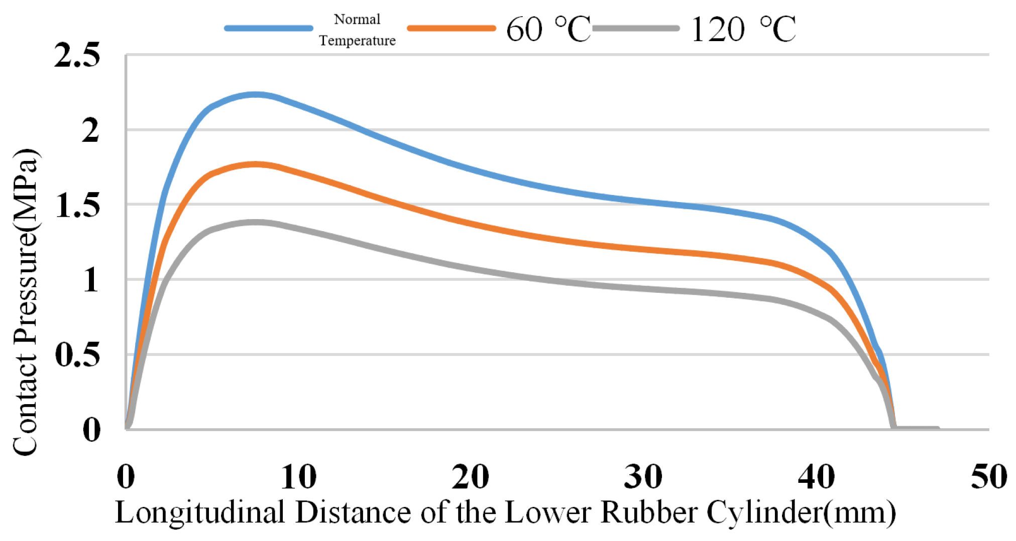
The downhole temperature of the CO2 injection wells is generally high, and the maximum temperature is usually close to 393 K. After the rubber is affected by temperature, its mechanical properties will be significantly affected. The contact pressure of the rubber cylinder decreases as the downhole working environment temperature increases. Figure 5, Figure 6 and Figure 7 show the simulation results of the contact stress of the lower, middle, and upper rubber cylinders after complete seating under steady–state conditions with normal temperatures, 363 K and 393 K, without considering the influence of the working pressure difference and swelling under SC–CO2 diffusion. As can be seen from the figures, as the temperature rose, the contact stress of the rubber cylinder decreased [30,31,32]. Under the steady–state condition of 393 K, the contact stress of the rubber cylinder was reduced by about 40% compared with that when it was just seated. In order to ensure a long–term seal at high temperatures, the rubber packer cylinder should be made of high–temperature–resistant materials to improve the contact stress after seating.

4.3. Effect of Working Pressure Difference on Sealing Performance of Rubber Cylinder

After the seating of the packer, the rubber cylinder bears the working pressure difference from the upper and lower injection systems. Figure 8 shows the contact pressure nephogram of the rubber cylinder under the steady–state condition of 393 K with working pressure differences of 5, 15, and 25 MPa, regardless of the influence of swelling under SC–CO2 diffusion. The figure shows that with the increase in the working pressure difference, the contact pressure of the rubber cylinder increased, and the stress distribution of the three rubber cylinders became more uniform. Within the deformation limit of the rubber cylinder, increasing the working pressure difference could increase the contact pressure between the rubber cylinder and the inner wall of the casing, thus enhancing the sealing effect. The sealing effects of the three rubber cylinders were compared horizontally, which showed that the sealing effect of the lower rubber cylinder was the best. Taking the working pressure difference of 5 MPa as an example, the maximum contact stress of the upper rubber cylinder was 5.43 MPa, with the difference being 0.43 MPa, and the maximum contact stress of the lower rubber cylinder was 6.38 MPa, with the difference being 1.38 MPa, compared with the working pressure difference of 5 MPa. Theoretically, the sealing effect could be ensured. However, during the actual application, the elasticity of the rubber would be decreased due to long–term high temperature and high pressure. Thus, there would be a risk of leakage and the loss of the seal for the upper and middle rubber cylinders if the seating mode with lower–end compression similar to the Y441–114 packer was used. Once the upper and middle rubber cylinders leaked and lost their sealing, or were torn, the stress of the lower cylinder would be directly changed, which would increase the risk of overall sealing failure. Therefore, in order to improve the contact stress distribution of the rubber cylinder in the seating process, the original unidirectional seating mode at the lower end should be changed, while the bidirectional seating mechanism should be designed to change the overall stress of the rubber cylinder, thus improving the contact stress distribution and enhancing the sealing effect.

4.4. Effect of SC–CO2 on Sealing Performance of Rubber Cylinder

The influence of SC–CO2 on the sealing performance of the rubber cylinder was calculated using the thermal analogy method, and the seating distance of 40 mm was set as the seating distance of the simulated rubber model. Because of the limited sealing volume of the downhole annulus, when the rubber cylinder was completely seated, the degree of SC–CO2 diffusion into the rubber cylinder body would be less than the results obtained via the indoor sampling experiment.
Therefore, the parameter scanning method was adopted, with the target temperature (SC–CO2 diffusion percentage) being used as the variable to carry out step–by–step scanning. When the volume of the rubber cylinder expanded to the limit of the wellbore, this was regarded as a complete swelling, and the final expansion coefficient was obtained. The volume strains of the rubber cylinder before and after swelling under SC–CO2 diffusion are shown in Figure 9a,b, respectively. The maximum volume strain in the rubber cylinder was 21.79% when SC–CO2 was not considered. When SC–CO2 diffused into the rubber cylinder, the maximum volume strain value increased to 26.52%, and the swelling effect caused the rubber cylinder to further expand to fill the entire sealing space.
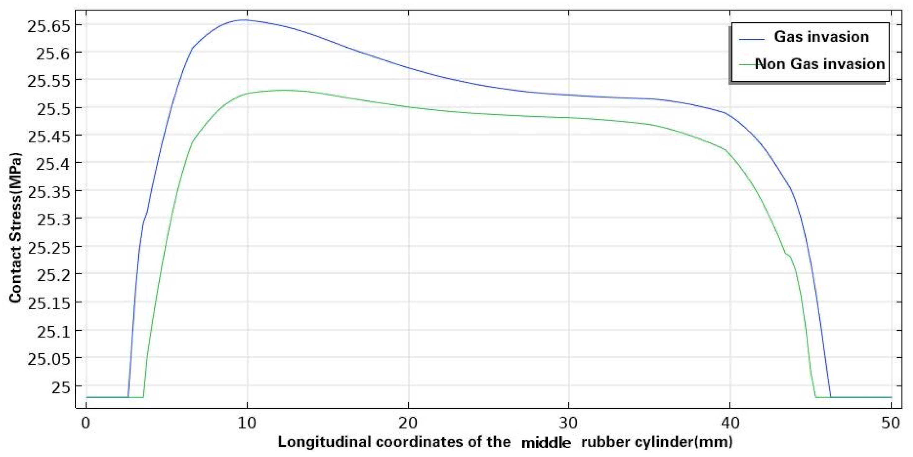
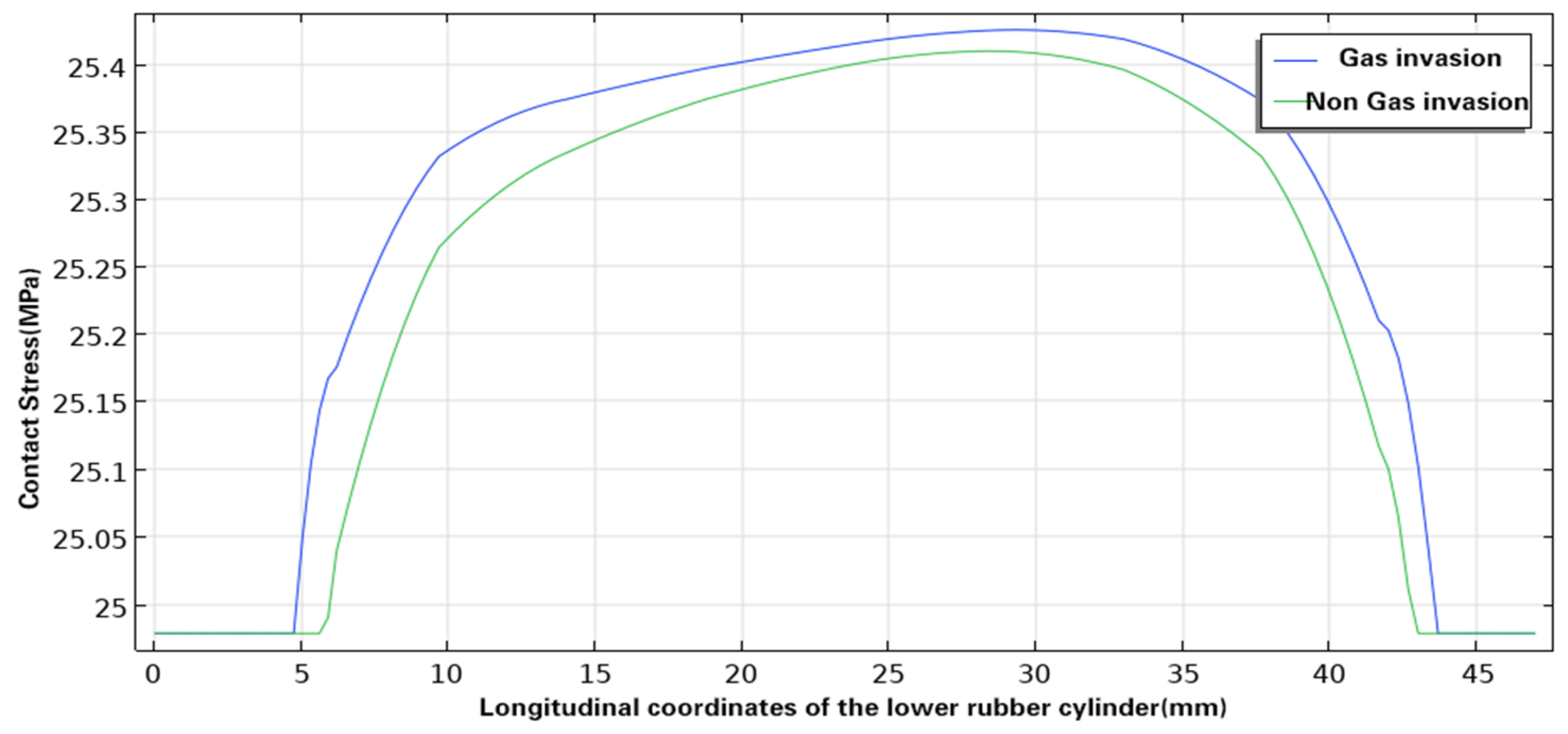
Figure 10, Figure 11 and Figure 12 show the contact pressures between the inner wall of the casing and the upper, middle, and lower rubber cylinders, respectively, before and after swelling under SC–CO2 diffusion. With the swelling under SC–CO2 diffusion, the contact pressure of the three rubber cylinders increased further, but the increase was small, with that of the upper rubber cylinder increasing from 26.38 MPa to 26.76 MPa, that of the middle rubber cylinder increasing from 25.53 MPa to 25.66 MPa, and that of the lower rubber cylinder increasing from 25.42 MPa to 25.45 MPa. At present, the rubber commonly used in a Y441–114 packer for gas injection is hydrogenated nitrile rubber, and its compressive strength is generally about 30 MPa. Thus, the pressure of the packer rubber cylinder was still within the allowable compressive strength after swelling under SC–CO2 diffusion.
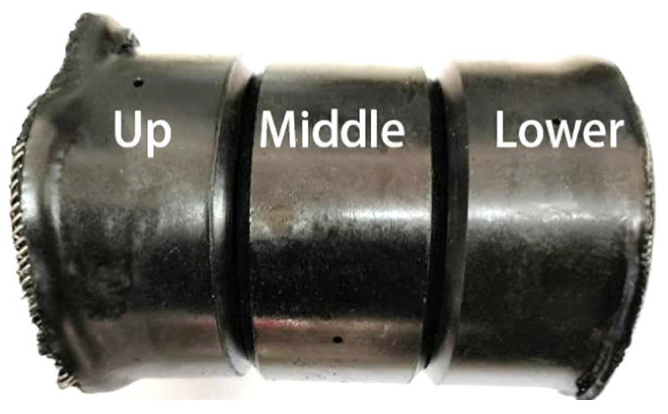
Figure 13 shows an image of the rubber packer cylinder taken from the CO2 layered injection well site, from which it can be seen that the upper and lower rubber cylinders have undergone large deformation and damage at the edges. It is known that the injection pressure of the well was about 20 MPa, and according to the simulation results, the maximum volume strain of the lower rubber cylinder should be lower than 20%, and the maximum contact stress should be lower than 26.76 MPa. It was inferred that the swelling effect under SC–CO2 diffusion was not the main factor that caused the rubber cylinder to tear due to deformation.
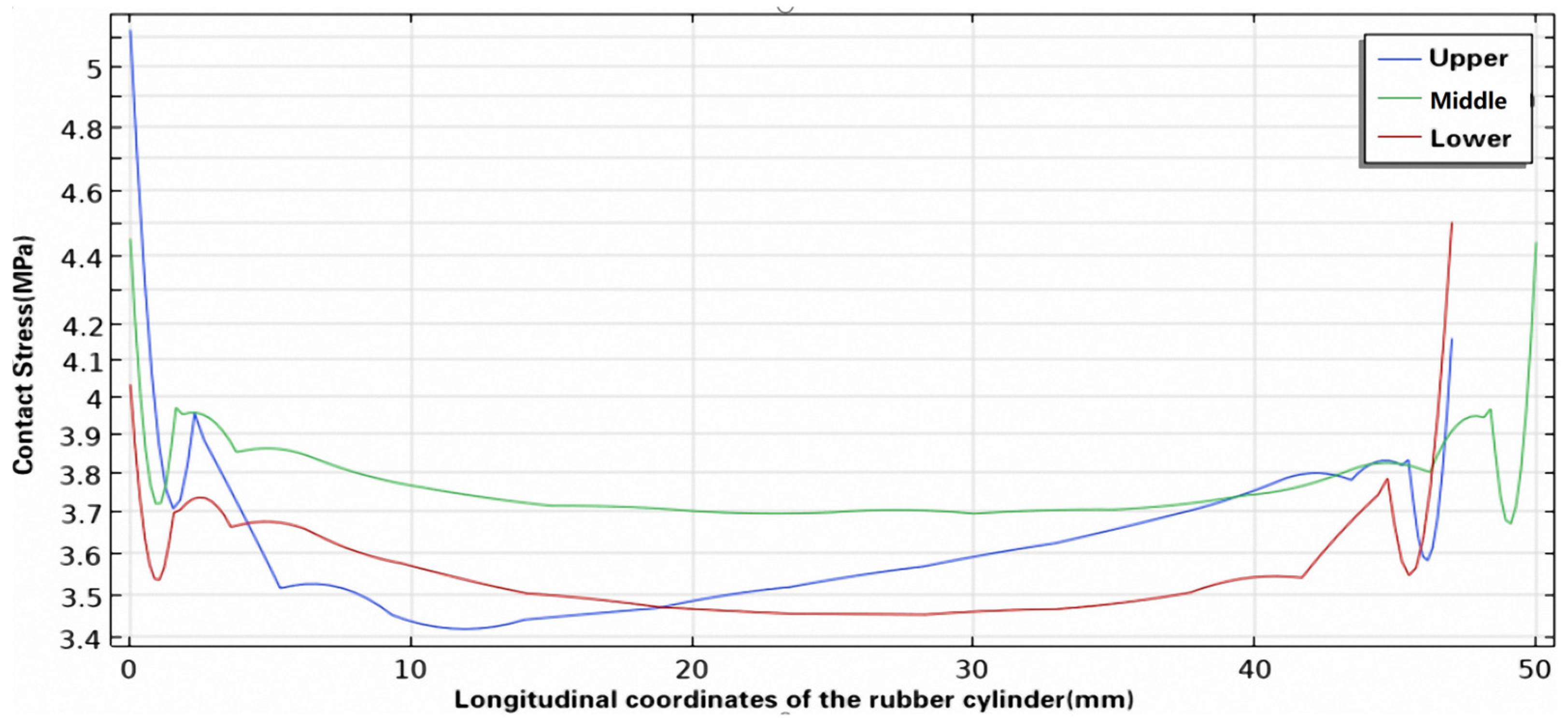
Figure 9c shows the volumetric strain cloud diagram of the expansion of the rubber cylinder under the influence of swelling under SC–CO2 diffusion after the packer became unseated. According to the swelling curve under the case of rapid decompression, the volume expansion of the rubber cylinder would be more than 200%. Therefore, even if the packer was completely unsealed, there was still contact stress between the rubber cylinder and the casing wall. Figure 14 shows the contact stress curve between the rubber cylinder and the inner wall of the casing after unsealing considering the influence of swelling under SC–CO2 diffusion. It can be seen from the curve that after unsealing, the lower edge of the lower rubber cylinder and the upper edge of the upper rubber cylinder were still affected by the swelling effect, and there were still large contact stresses. This is consistent with the actual situation in the field, with the contact stress at the lower edge of the lower rubber cylinder being more than 5 MPa, the upper and lower edges of the middle rubber cylinder being close to 4.5 MPa, and the upper edge of the upper rubber cylinder being close to 4 MPa. According to the simulation results in Figure 10, Figure 11 and Figure 12, when the packer was fully seated, the contact length between the lower rubber cylinder and the casing was about 45 mm, the contact length between the middle rubber cylinder and the casing was 40 mm, and the contact length between the upper rubber cylinder and the casing was 37 mm. The inner diameter of the casing was 124 mm. When the packer was unsealed, the space between the rubber cylinder and the casing was filled with injected gas, and the friction coefficient could be set as 0.1. The frictions between the inner wall of the casing and the lower, middle, and upper rubber cylinders were 87.61 kN, 70.08 kN, and 57 kN, respectively. It can be inferred that during the unsealing process, SC–CO2 diffused into the rubber cylinder and caused the swelling, which enhanced the residual friction between the rubber cylinder and the casing wall. During the operation of pipe string lifting in the field, deformation damage and tearing of the rubber cylinder usually occur, and the maximum probability of tearing appeared at the lower edge of the lower rubber cylinder and the upper edge of the upper rubber cylinder; this also verified the above conclusions.
In the CO2 injection well with two injection sections, generally, two sets of packers are used to protect the casing from corrosion, and another set of packers is used to separate the upper and lower sections. The release force of the three sets of packers was calculated as about 64.59 t according to the above method. The rated lifting load of the conventional workover rig is 30 t, and the rated lifting load of the workover rig under high–pressure operation is 60 t. It can be seen that the residual friction between the rubber cylinder and the inner wall of the casing is also one of the main reasons for the pipe being stuck during field operation. Therefore, when designing the packer for CO2 injection, a step–by–step release mechanism should be utilized to reduce the release force of the string and improve the success rate of the operation.

5. Conclusions

(1)
Unidirectional compression seating at the lower end is usually used for conventional packers. The simulation results show that the deformation of the three rubber cylinders was uneven, and if the seating distance is not set reasonably, this can easily lead to the tearing and damage of the rubber cylinder. Therefore, when designing the seating mechanism of a packer, a reasonable seating distance should be retained to prevent poor sealing or damage to the rubber cylinder. Further, the seating mechanism should be optimized and upgraded, such as by using a bidirectional seating mechanism, to fundamentally change the overall stress of the rubber cylinder and improve the sealing reliability.
(2)
The downhole temperature of CO2 injection wells usually exceeds 373 K, and the simulation results show that the contact stress between the rubber cylinder and the inner wall of the casing decreases significantly with an increase in downhole temperature. Under the steady–state condition of 393 K, the contact stress of the rubber cylinder decreases by about 40% compared with that when it is just seated. In order to ensure long–lasting sealing under high–temperature conditions, the rubber packer cylinders selected for CO2 injection wells should have the characteristics of high temperature resistance.
(3)
The thermal analogy method was used to simulate the effect of SC–CO2 on the sealing performance of rubber cylinders, and the results show that with the rubber swelling under SC–CO2 diffusion, the deformation of the rubber cylinder is enhanced, and the contact stress between the rubber cylinder and the inner wall of the casing is increased. However, the deformation is small, which will not result in the tearing of the cylinder.
(4)
The simulation results show that in the process of the packer unsealing, the swelling effect greatly increases the contact stress between the rubber cylinder and the inner wall of the casing, thus increasing the overall unsealing force of the pipe string. If more than three sets of packers were applied to a gas injection well, the unsealing force would be more than 60 t, which would disable the normal pipe string operation. Therefore, when designing or selecting packers for CO2 injection, attention should be paid to whether they have the function of step–by–step releasing, to reduce the difficulty of field operation.
(5)
The above conclusions were made after the digital simulation of a rubber cylinder made of hydrogenated nitrile, providing a certain reference for cylinders made of other types of rubber.

Author Contributions

Conceptualization, Z.Z.; methodology, Z.Z.; validation, M.C.; formal analysis, L.C.; investigation, X.S.; resources, X.X.; data curation, C.C.; writing—original draft preparation, H.L.; writing—review and editing, Q.G. All authors have read and agreed to the published version of the manuscript.

Funding

This research was funded by the Technology Project of CNPC–Research on Key Technologies of CCUS Injection and Production Process, Produced Gas Recycling and Efficient Anti corrosion (2021ZZ01–04), the Technology Project of CNPC–Integration and Industrialization Test of CCUS Technology in the Songliao Basin (Daqing, Jilin) (2021ZZ01–08), and the Technology Project of CNPC–Research on the Process Technology for Tertiary Oil Recovery in Low–permeability/Tight Oil Reservoirs (2023ZZ17–05).

Data Availability Statement

The original contributions presented in the study are included in the article; further inquiries can be directed to the corresponding author.

Conflicts of Interest

Authors Zhenkun Zhu, Meng Cai, Xingliang Song, Xiaoyu Xu, Haicheng Li, Qiming Gao were employed by the company Daqing Oilfield Co., Ltd. Author Lining Cui was employed by the company PetroChina. The remaining authors declare that the research was conducted in the absence of any commercial or financial relationships that could be construed as a potential conflict of interest.

References

  1. Rui, Z.; Li, Y.; Xue, Z.; Liu, Y. Development Suggestions on Key Technologies of CO2 Enhanced Oil and Gas Recovery and Geological Storage. Prospect. Sci. Technol. 2023, 2, 145–160. [Google Scholar]
  2. Zhu, D.; Lin, Y.; Zou, D.; Li, Y. Study on Corrosion Mechanical Properties of Rubber Material for CO2 Flooding Gas Well Packer. Pet. Drill. Tech. 2014, 42, 5. [Google Scholar]
  3. Zhang, K.; Chen, Z.X.; Lan, H.F.; Ma, H.M.; Jiang, L.L.; Xue, Z.Q.; Zhang, Y.M.; Cheng, S.X. Status and Prospect of Carbon Capture, Utilization and Storage Technology. Spec. Oil Gas Reserv. 2023, 30, 1–9. [Google Scholar]
  4. Aminu, M.D.; Nabavi, S.A.; Rochelle, C.A.; Manovic, V. A Review of Developments in Carbon Dioxide Storage. Appl. Energy 2017, 208, 1389–1419. [Google Scholar] [CrossRef]
  5. Baklid, A.; Korbol, R.; Owren, G. Sleipner Vest CO2 Disposal, CO2 Injection into a Shallow Underground Aquifer. In Proceedings of the SPE Annual Technical Conference and Exhibition, Denver, CO, USA, 6–9 October 1996; p. SPE–36600–MS. [Google Scholar]
  6. Cook, P.J. CCS Research Development and Deployment in a Clean Energy Future: Lessons from Australia over the Past two Decades. Engineering 2017, 3, 477–484. [Google Scholar] [CrossRef]
  7. Wang, F.S.; Xu, D.K.; Li, K.L.; Li, J.Y.; Wang, L.J. Research on Sealing Mechanism of CO2 Packer Cartridge. J. Oil Prod. Eng. 2018, 3, 1–4+84. [Google Scholar]
  8. Liu, J.X.; Wang, S.J.; Zhang, R.X.; Wei, W. Bidirectional Compression Packer for Stratified Gas Injection in CO2 Flooding. China Pet. Mach. 2017, 45, 87–89. [Google Scholar]
  9. Zhang, X.; Xu, X.P.; Wang, L. Improvement and Advantage Analysis of Packer Rubber Cylinder Structure. Oil Field Mach. 2013, 1, 62–66. [Google Scholar]
  10. Zhang, Z.; Zhu, X.H.; Xu, J.B. Optimization of Structural Parameters of a Compression Packer Casing Based on Orthogonal Tests. Nat. Gas Ind. 2019, 39, 80–84. [Google Scholar]
  11. Daou, F.; de Miranda, C.R.; De Oliveira, J.L.; Engelke, B.; Borman, C.; Le Roy–Delage, S.; Lungwitz, B. Swelling of Elastomers in CO2 Environment: Testing Methodology and Experimental Data. In Proceedings of the SPE Latin America and Caribbean Petroleum Engineering Conference, Maracaibo, Venezuela, 21–23 May 2014; p. D031S023R002. [Google Scholar]
  12. Zhu, D.; Lin, Y.; Zhang, H.; Li, Y.; Zeng, D.; Liu, W.; Qiang, C.; Deng, K. Corrosion Evaluation of Packer Rubber Materials in CO2 Injection Wells under Supercritical Conditions. J. Pet. Sci. Eng. 2017, 151, 311–317. [Google Scholar] [CrossRef]
  13. Davies, O.M.; Arnold, J.C.; Sulley, S. The Mechanical Properties of Elastomers in High–pressure CO2. J. Mater. Sci. 1999, 34, 417–422. [Google Scholar] [CrossRef]
  14. Yamabe, J.; Nishimura, S. Failure Behavior of Rubber O–ring under Cyclic Exposure to High–pressure Hydrogen Gas. Eng. Fail. Anal. 2013, 35, 193–205. [Google Scholar] [CrossRef]
  15. Wang, J.L.; Gao, B.K.; Ma, C.; Chen, X.W. Effect of Casing Wear on Sealing Performance of Packer. Pet. Mach. 2021, 9, 55–60. [Google Scholar]
  16. Ge, Y. Research on Structure Design and Performance of Rubber Cylinder of New Gas Injection Packer. Ph.D. Thesis, China University of Petroleum, Beijing, China, 2022. [Google Scholar]
  17. Wang, L.; Xu, P.; Tao, J.H. Finite Element Analysis of Rubber O–ring Static Seal Structure in High–pressure Hydrogen Environment. Manuf. Autom. 2022, 46, 143–149. [Google Scholar]
  18. Wang, W. Coupling Simulation of Hydrogen Concentration Field and Stress Field Based on Thermal Analogy. Ph.D. Dissertation, Huazhong University of Science and Technology, Wuhan, China, 2018. [Google Scholar]
  19. Liu, M.T. Study on the Swelling Law of Hydrogenated Nitrile Butadiene Rubber and Fluorine Rubber in Carbon Dioxide. Ph.D. Thesis, China University of Petroleum, Beijing, China, 2021. [Google Scholar]
  20. Jin, L.; Li, S.; Cheng, Y.; Liu, J. A time–dependent Yeoh model to predict the corrosion effect of supercritical CO2 on the HNBR sealing rubber. J. Mech. Sci. Technol. 2022, 36, 2461–2470. [Google Scholar] [CrossRef]
  21. Huang, X.M.; Xiao, G.H.; Wang, L. Design and Development of Plug–in High Temperature and High Pressure Gas Injection Packer. Xinjiang Oil Gas 2023, 19, 21–25. [Google Scholar]
  22. Wang, Z.Y.; Liu, Y.J.; Zhu, S.; Dou, Y.H. Nonlinear Simulation and Performance Evaluation of Packer Cartridge. Inf. Technol. 2023, 52, 112–116. [Google Scholar]
  23. Huang, L.; Guo, Z.L.; Wang, X.L.; He, F.G.; Wu, C.H.; Li, W.B. Failure Analysis and Improvement Design of Packer Seal Casing Extrusion. Hydraul. Pneum. 2023, 47, 177–182. [Google Scholar]
  24. Mao, J. Development of Rubber Casing for High Temperature and High Pressure Test Packer. Oil Drill. Prod. Technol. 2023, 45, 638–643. [Google Scholar]
  25. Sun, Y.; Wei, A.; Chen, Z.; Cheng, W.; Cai, Y. Sealing Structure Design of Rubber Cylinder for High Temperature and High Pressure Packer. Lubr. Seal. 2023, 48, 140–145. [Google Scholar]
  26. Yue, Q.B.; Wang, G.; Liu, J.B.; Sun, G.H.; Wang, X.X.; Liu, Y.Q.; Cao, W.; Zhang, Q. Simulation and Calculation of Nonlinear Flow in Expansion Packer under High Temperature and Pressure. Chin. J. Comput. Mech. 2023, 40, 411–423. [Google Scholar]
  27. Kim, B.; Lee, S.B.; Lee, J.; Cho, S.; Park, H.; Yeom, S.; Han Park, S. A Comparison Among Neo–Hookean Model, Mooney–Rivlin Model, and Ogden Model for Chloroprene Rubber. Int. J. Precis. Eng. Manuf. 2012, 13, 759–764. [Google Scholar] [CrossRef]
  28. Zhong, W. Research on Sealing Performance of Packer Rubber Casing. Ph.D. Thesis, China University of Petroleum, Beijing, China, 2022. [Google Scholar]
  29. Koga, A.; Uchida, K.; Yamabe, J. Evaluation on High–pressure Hydrogen Decompression Failure of Rubber O–ring Using Design of Experiments. Int. J. Automot. Eng. 2011, 2, 123–129. [Google Scholar] [CrossRef] [PubMed]
  30. Li, Y.; Shi, C.; Pan, X.; Yang, L. Influence of Supercritical Carbon Dioxide–Assisted Polyamide Acid Modification of Aramid Fibers on the Properties of Aramid Fiber–Reinforced Styrene Butadiene Rubber. J. Fibers Polym. 2024, 25, 2117–2130. [Google Scholar] [CrossRef]
  31. Gumerov, F.M.; Zaripov, Z.I.; Khairutdinov, V.F.; Sagdeev, D.I. Universality of Supercritical Carbon Dioxide in the Process of Tertiary Oil Production. J. Theor. Found. Chem. Eng. 2023, 57, 45–55. [Google Scholar] [CrossRef]
  32. Guo, H.; Wang, Y.; Tan, L.; Lu, Z.; Bai, L. Corrosion Behaviors of Iron in a Supercritical CO2 Environment: A Molecular Dynamics Study. J. Mater. Sci. 2023, 58, 14758–14772. [Google Scholar] [CrossRef]
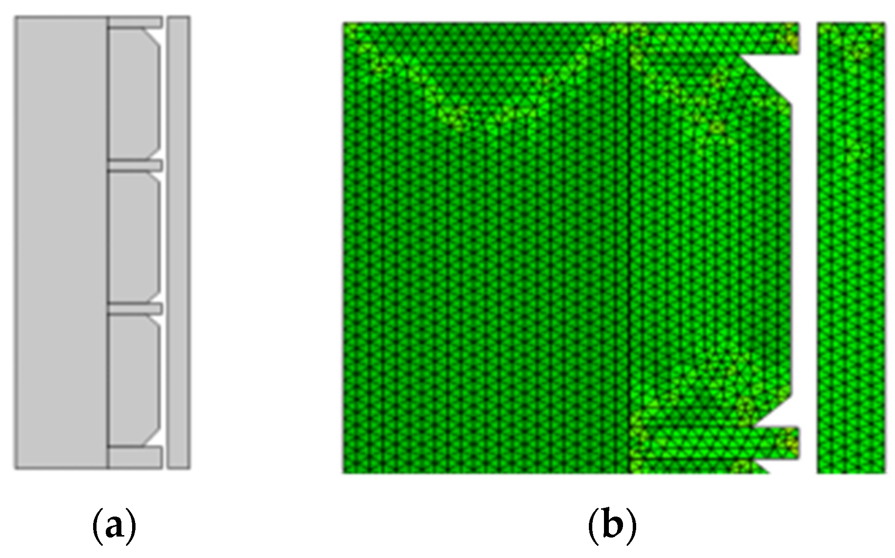
Figure 1. Finite element model and mesh division of the rubber cylinder. (a) Finite element model. (b) Mesh division.
Energies 17 03305 g001
Figure 2. Change in rubber swelling volume with time [19].
Energies 17 03305 g002
Figure 3. von Mises stress nephogram of a rubber cylinder. (a) Seating distance 25 mm. (b) Seating distance 30 mm. (c) Seating distance 40 mm.
Energies 17 03305 g003
Figure 4. Contact pressure nephogram between the rubber cylinder and the inner wall of the casing. (a) Seating distance 25 mm. (b) Seating distance 30 mm. (c) Seating distance 40 mm.
Energies 17 03305 g004
Figure 5. Contact stress of the upper rubber cylinder under different temperature conditions.
Energies 17 03305 g005
Figure 6. Contact stress of the middle rubber cylinder under different temperature conditions.
Energies 17 03305 g006
Figure 7. Contact stress of the lower rubber cylinder under different temperature conditions.
Energies 17 03305 g007
Figure 8. Contact pressure nephogram of a rubber cylinder under varying working pressure difference conditions. (a) Working pressure difference of 5 MPa. (b) Working pressure difference of 15 MPa. (c) Working pressure difference of 25 MPa.
Energies 17 03305 g008
Figure 9. Comparison of the volumetric strain of the rubber cylinder before and after swelling and nephogram of volumetric strain after unsealing. (a) Volume strain after compression (swelling under SC–CO2 diffusion was not considered). (b) Volume strain after compression (swelling under SC–CO2 diffusion was considered). (c) Volume strain after unseating (swelling under SC–CO2 diffusion was considered).
Energies 17 03305 g009
Figure 10. Comparison of the contact pressure between the upper rubber cylinder and the inner wall of the casing before and after swelling under SC–CO2 diffusion.
Energies 17 03305 g010
Figure 11. Comparison of the contact pressure between the medium rubber cylinder and the inner wall of the casing before and after swelling under SC–CO2 diffusion.
Energies 17 03305 g011
Figure 12. Comparison of the contact pressure between the lower rubber cylinder and the inner wall of the casing before and after swelling under SC–CO2 diffusion.
Energies 17 03305 g012
Figure 13. Picture of rubber packer cylinder.
Energies 17 03305 g013
Figure 14. Comparison of the contact pressure between the rubber cylinder and the inner wall of the casing after unsealing (swelling under SC–CO2 diffusion was considered).
Energies 17 03305 g014
Table 1. The value of C10 and C01 in the Mooney–Rivlin model of packer rubber [28].
TemperatureC10 (MPa)C01 (MPa)
Room temperature0.8870.443
333 K0.7470.298
393 K0.5830.233
Disclaimer/Publisher’s Note: The statements, opinions and data contained in all publications are solely those of the individual author(s) and contributor(s) and not of MDPI and/or the editor(s). MDPI and/or the editor(s) disclaim responsibility for any injury to people or property resulting from any ideas, methods, instructions or products referred to in the content.