Article

Comparison of Maximum Heat Transfer Rate of Thin Vapor Chambers with Different Wicks under Multiple Heat Sources and Sinks

1
School of Aerospace and Mechanical Engineering, Korea Aerospace University, Goyang 10540, Gyeonggi-do, Republic of Korea
2
School of Smart Air Mobility Engineering, Korea Aerospace University, Goyang 10540, Gyeonggi-do, Republic of Korea
*
Author to whom correspondence should be addressed.
Energies 2024, 17(13), 3330; https://doi.org/10.3390/en17133330 (registering DOI)
Submission received: 16 May 2024 / Revised: 28 June 2024 / Accepted: 4 July 2024 / Published: 7 July 2024
(This article belongs to the Section J1: Heat and Mass Transfer)

Abstract

:
In this paper, we present a new analytical model to investigate the maximum heat transfer rate of a thin vapor chamber (TVC) with multiple heat sources and sinks. The model can specifically consider different heat flux conditions for each heat source. Both capillary limitations and allowable maximum temperature constraints were employed to determine the maximum heat transfer rate. The liquid and vapor pressure distributions within the TVC were analytically derived using the Brinkman-extended Darcy equation and the Hagen–Poiseuille equation, respectively. Additionally, the theoretical wall temperature distribution was calculated based on the 3D energy equation, considering different heat flux conditions for multiple heat sources with a weighting factor. Our results demonstrate that the heat flux conditions applied to the heat sources significantly impact the internal flow pattern of the TVC. These changes in flow patterns influence the pressure distributions of the liquid and vapor, thereby affecting the maximum heat transfer rate. Furthermore, the effects of wick parameters on the maximum heat transfer rate under various heat flux conditions were examined.

1. Introduction

Many compact electric power-based devices consist of various components, each of which generates significant amounts of heat simultaneously. Particularly, the maximum temperature of electric power-based devices should be maintained at less than 80 °C to prevent the deterioration of electric devices’ performance [1,2]. In order to reduce the maximum temperature of power-based components, many researchers have made great efforts to efficiently spread heat by using high-thermal conductivity materials such as copper sheets and graphite sheets in narrow spaces of less than 1~2 mm [3,4,5,6]. However, the thickness of heat spreaders using copper or graphite sheets near 1 mm presents challenges in efficient heat dissipation. So, many researchers have focused on thin flat heat spreaders or thin vapor chambers (TVCs) to address the challenges, highlighting their advantages, including high thermal conductivity (over 10,000 W/m·K), lightness, reliability, and a relatively long lifespan. For example, Li et al. [7] investigated the effect of the superhydrophilicity of a screen mesh wick on the capillary force of a thin flat heat spreader with 0.5 mm thickness. They presented the effective thermal conductivity of the heat spreader which can be applied to a simplified specific system. Moreover, Huang et al. [8] optimized the total size, the wick thickness, and the height of the vapor core to maximize the heat transfer rate of TVCs with a screen mesh wick. Li et al. [9] suggested the optimized number and width of radially grooved channels. Ranjan et al. [10] numerically optimized the wick in a 3 mm thick flat vapor chamber designed for use at high heat fluxes exceeding 50 W/cm2. The wick utilized a screen mesh wick with a thickness of less than 0.5 mm, and the thermal resistance and pressure drop were predicted based on the wick thickness. Li et al. [11] theoretically and experimentally studied the performance of a flat vapor chamber with support columns. Specifically, they theoretically predicted and experimentally validated the pressure distribution and temperature distribution according to wick thickness and the vapor core. Additionally, using the theoretical model, they presented the pressure loss with and without support columns and its impact on heat transfer performance. However, they [7,8,9,10,11] only considered a vapor chamber or a thin flat heat spreader with a single heat source and sink, despite the need for analyzing a thin vapor chamber capable of uniformly distributing heat from multiple heat sources. So, Lefevre and Lallemand [12] proposed thermodynamic and hydrodynamic models to theoretically predict the performance of flat micro heat spreaders with multiple heat sources and sinks in steady-state conditions. Recently, Subedi et al. [13] optimized the geometry of screen mesh wicks in TVCs considering the Brinkman effect in the screen wick. However, both analytical models [12,13] have a significant limitation. They assumed that the heat flux of all heat sources remains constant and of the same magnitude, even though the size of the heat source can be adjusted in various ways. Particularly, to the best of the authors’ knowledge, there are no comparative results available to predict which type of wick (screen mesh, grooved, or sintered wicks) can produce the maximum heat transfer rate in TVCs with multiple heat sources and sinks.
In this paper, the modified analytical model for predicting the maximum heat transfer rate of a TVC with multiple heat sources and sinks was presented by considering different heat flux conditions for each heat source. In particular, we presented the results of comparing the maximum heat transfer rates of TVCs with three types of wicks, screen mesh, grooved, and sintered wicks, according to wick thickness and the different heat flux conditions of multiple heat sources. Finally, the effects of the key engineering parameters of the wicks such as screen mesh, grooved, and sintered wicks on the maximum heat transfer rate of a TVC with multiple heat sources and sinks were shown.

2. Analytical Model

In this paper, a TVC with three heat sources (E1, E2, and E3) and two heat sinks (C1 and C2) is modeled, as shown in Figure 1a. D.I. water and copper are employed as working fluid and wall material. Also, it is assumed that all properties are constant at the saturated temperature of working fluids, and gravitational force is negligible. As shown in Figure 1b, a TVC consists of vapor chamber wall (a solid wall), a wick (porous medium), and a vapor space.

2.1. Temperature Distribution Model

The Fourier series solution of the 3D energy equation presented by Lefevre and Lallemand [12] and Subedi et al. [13] is used to obtain the temperature distributions in the vapor chamber wall, as shown in Figure 1b. The energy equation can be simplified as shown in Equation (1).
ρ C p D T D t = k w a l l 2 T
where Cp, kwall, ρ, and T are the specific heat, thermal conductivity of the wall, density, and temperature, respectively. Non-dimensional parameters are defined by
T * = k w a l l c φ o T T s a t ,   B i = h c k w a l l ,   β = b a ,   γ = c a ,   X = x a ,   Y = y b ,   Z = z c
where a, b, c, Tsat, T*, and φo are the length of the x-direction, length of the y-direction, height of the wall, saturation temperature, dimensionless temperature, and imposed heat flux, respectively. Bi, h, β, and γ are the Biot number, equivalent heat transfer coefficient, and dimensionless lengths, respectively. To apply a different heat flux condition on each heat source, weighting factor κ is used, as in Equation (3).
φ i = κ i φ o ,   where   φ o = i = 1 n s o u r c e φ i
where κi is the weighting factor of the ith heat sources. By substituting Equation (2) into Equation (1), the non-dimensional energy equation can be given by
2 T * X 2 + 1 β 2 2 T * Y 2 + 1 γ 2 2 T * Z 2 = 0
The boundary conditions to solve Equation (4) are given by
T * X X = 0 = T * X X = 1 = T * Y Y = 0 = T * Y Y = 1 = 0
T * Z Z = 0 = B i T *
T * Z Z = 1 = ϕ X , Y = κ i in   i th   heat   source   area 0 in   adiabatic   area η in   heat   sin k   area   where   η = i = 1 n A e , i i = 1 n A c , i
where Ac, Ae, and η are the condenser area, evaporator area, and ratio of the heat sink area to heat source area, respectively. The non-dimensional temperature (T*) as given by Equation (8) is determined as the form of 2-variable Fourier series.
T * = m = 1 A m 0 Z cos m π X + n = 1 A 0 n Z cos n π Y + n = 1 m = 1 A m n ( Z ) cos m π X cos n π Y
The non-dimensional heat flux ( ϕ ) can be obtained by
ϕ X , Y = m = 1 B m 0 cos m π X + n = 1 B 0 n cos n π Y + n = 1 m = 1 B m n cos m π X cos n π Y
The Fourier coefficients of Am0, A0n, Amn, Bm0, B0n, and Bmn were described in Lefevre and Lallemand [12] and Subedi et al. [13].

2.2. Hydrodynamic Models

The liquid pressure drop through the wick structure such as screen mesh, grooved, and sintered wicks can be obtained from the Brinkman-extended Darcy equation which is considered by the no-slip condition of the wall [13].
P l = μ K u l + μ 2 u l Z 2
where K, Pl, ul, and μ are permeability, liquid pressure, the Darcy velocity of liquid, and the dynamic viscosity of liquid, respectively. The solution of liquid pressure [13] is given by
P l = μ l ω K h l v ρ l H w m = 1 C m 0 cos m π X + n = 1 C 0 n cos n π Y + n = 1 m = 1 C m n cos m π X cos n π Y
ω = 1 1 H w 2 K exp H w / K 1 exp H w / K + 1 1
where hlv, Hw, and ω are the latent heat of vaporization, wick thickness, and liquid pressure drop coefficient by the no-slip condition, respectively.
The vapor pressure distribution can be predicted from the Hagen–Poiseuille equation [12,13]. The vapor pressure distribution is given by
P v = 12 H v 3 μ v h l v ρ v m = 1 C m 0 cos m π X + n = 1 C 0 n cos n π Y + n = 1 m = 1 C m n cos m π X cos n π Y
where Hv, μv, and ρv are the thickness of the vapor core, dynamic viscosity of vapor, and vapor density, respectively. The Fourier coefficients Cm0, C0n, and Cmn which are considered by different heat flux conditions for each heat source with the weighting factor are obtained as given by
C m 0 = κ i φ t o t a l B i a m π 2 A m 0 0 ,   C 0 n = κ i φ t o t a l B i b n π 2 A 0 n 0 ,   C m n = κ i φ t o t a l B i A m n 0 m π a 2 + n π b 2

2.3. Theoretical Approach for Maximum Heat Transfer Rate of TVCs

To determine the maximum heat transfer rate of TVCs, the capillary limitation defined by the Young–Laplace equation [14,15], Equation (15) is used.
P c a p Δ P l + Δ P v ,   P c a p = 2 σ l r e f f cos θ
where Pcap, r e f f , σ l , and θ are capillary pressure, effective pore radius, the surface tension of liquid, and contact angle, respectively. Additionally, the allowable maximum temperature constraint [13,16] was used to prevent the temperature of the TVC surface from exceeding the maximum allowable temperature when obtaining the maximum heat transfer rate of the TVC. In this paper, the allowable maximum temperature constraint is set as 80 °C. Three types of wicks such as screen mesh, grooved, and sintered wicks are considered in the TVC, as shown in Figure 2. The wick parameters affecting temperature distribution, pressure distributions, and the maximum heat transfer rate are defined as
Screen mesh wick [12,13,17]:
H w = 2 d ,   N = 1 d + w ,   ε = 1 1.05 π N d 4 ,   K = d 2 ε 3 122 1 ε 2 ,   r e f f = d + w 2
where d, N, w, and ε are wire diameter, mesh number, the separation distance of wires, and porosity, respectively. In Equation (16), the engineering key parameters of the screen mesh wick are the wire diameter (d) and separation distance of wires (w).
Grooved wick [17,18,19]:
H w = H g ,   D h = 4 H g d g 2 H g + d g ,   ε = d g d g + w f ,   K = D h 2 ε 2 f   Re l , h ,   r e f f = d g
f   Re l , h = 24 1 1.355 Λ + 1.947 Λ 2 1.701 Λ 3 + 0.956 Λ 4 0.254 Λ 5 ,   Λ
where dg, Dh, f Re, Hg, and wf are the distance of the groove, hydraulic diameter, Poiseuille number, the height of the groove, and fin width, respectively. The major parameters of the grooved wick are the height of the groove (Hg), distance of the groove (dg), and fin width (wf). To reduce the number of major parameters to two variables, the fin width is determined by Equation (19) with a fixed porosity and distance of the groove.
w f = d g ε d g
In the present case, the engineering key parameters of the grooved wick are the height of the groove (Hg) and distance of the groove (dg).
Sintered wick [17,20,21,22,23,24]:
ε = 1 V p 6 V b V c u b e ,   V p = 4 3 π D 2 3 ,   V b = π D 2 3 α + 1 3 { ( 1 α ) 3 1 } ,   V c u b e = D 3 1 α 3
where D, Vb, Vcube, Vp, and α are the diameter of the particle, half of the bonded volume between two particles, volume of a cube, volume of a particle in a cube, and overlap ratio of particles, respectively. Particularly, the overlap ratio of particles, α, can be expressed by
α = 1 D * D
where D* is the effective diameter of the particle. The overlap ratio of particles was determined by manufacturing conditions such as sintering temperature and time and can be experimentally obtained. So, in this paper, it is assumed that α is fixed at 0.025 [25,26,27,28,29,30,31]. Also, the wick thickness, permeability, and effective radius can be given by
H w = n p D 1 α ,   K = 0.42 D 2 ε 32 ,   r e f f = 0.205 D
where np is the number of particles. Therefore, in this study, the particle diameter (D) and wick thickness (Hw) are considered as the engineering key parameters of the sintered wick.
By utilizing the definition of wick parameters, the key engineering parameters affecting the maximum heat transfer for screen mesh, grooved, and sintered wicks into two variables each are summarized. The effects of the engineering key parameters on the maximum heat transfer rates of TVCs are presented.

2.4. Validation

The present model is validated with previous results [12]. The porous medium of screen mesh wicks, wall material of copper, working fluid of water, and the same heat flux condition presented by a previous model [12] are used. As shown in Figure 3, the wall temperature and pressure distributions are well matched with previous results [12]. From the results of validation, the maximum heat transfer rate was 76.6 W, which is within a 1% difference from the previous research [12] result of 76 W. The gray contour and solid lines are the temperature difference and liquid pressure lines, respectively, from a previous model [12]. The color dotted lines are the results calculated by the present study.

3. Results and Discussion

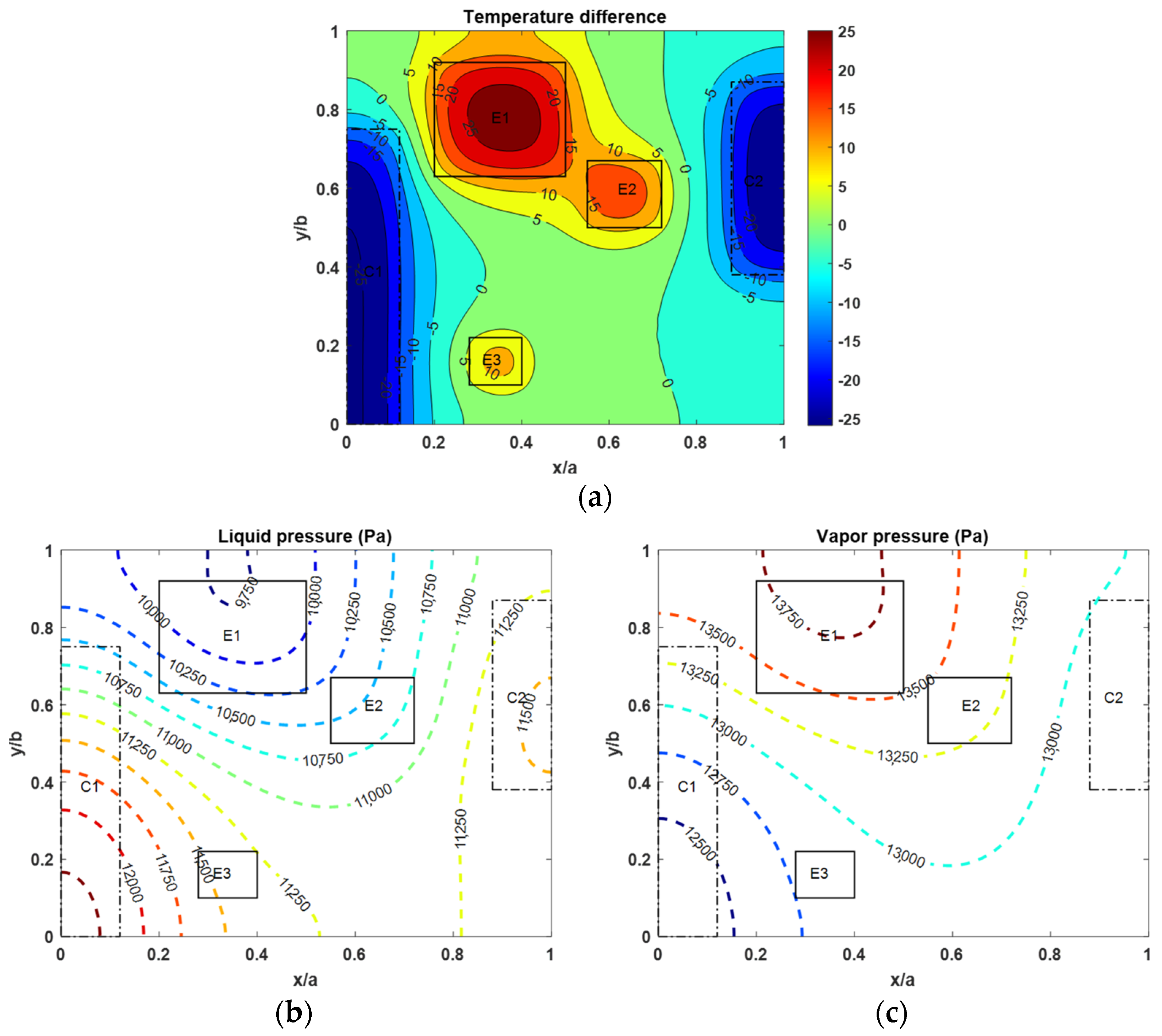
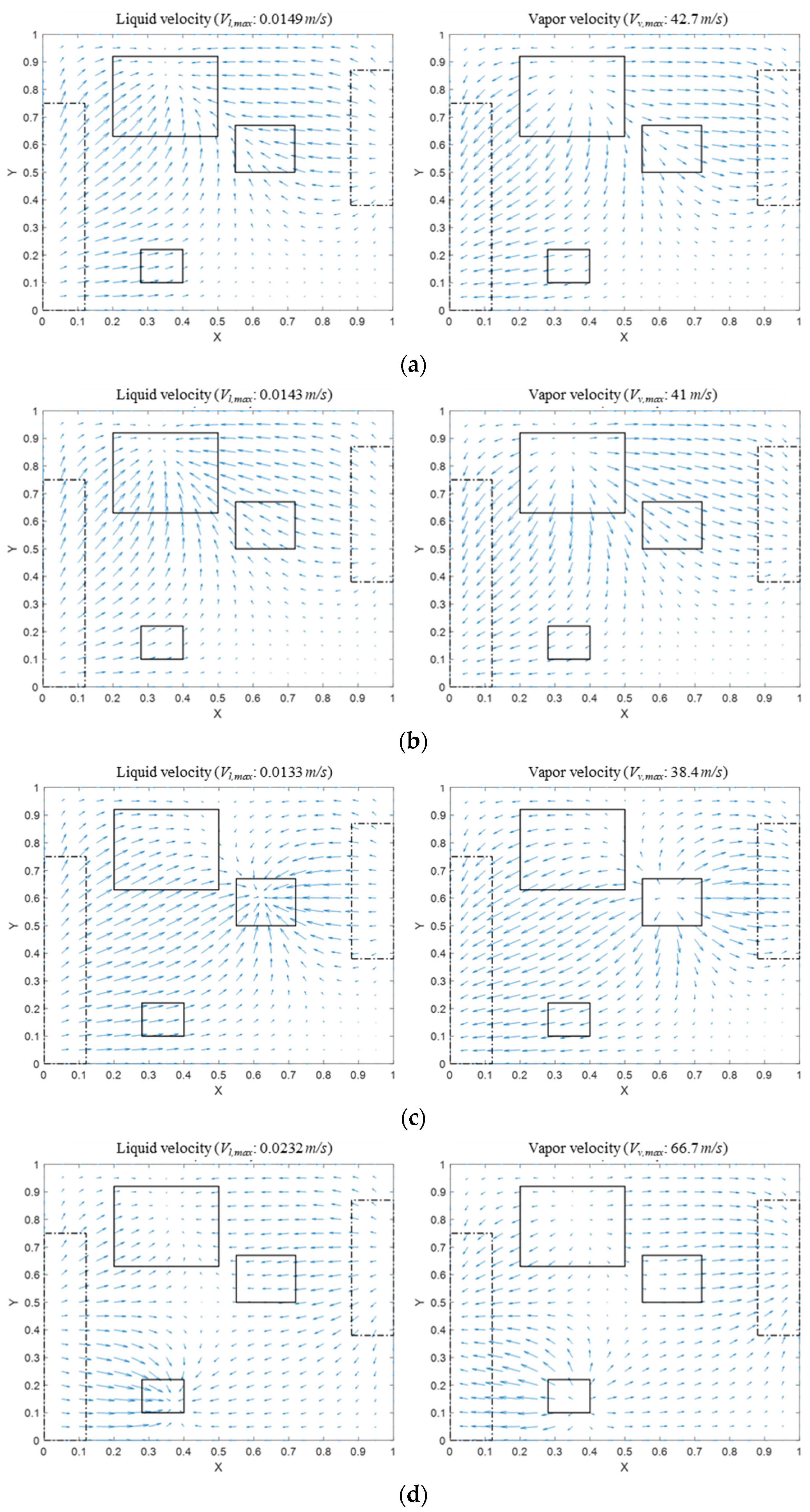
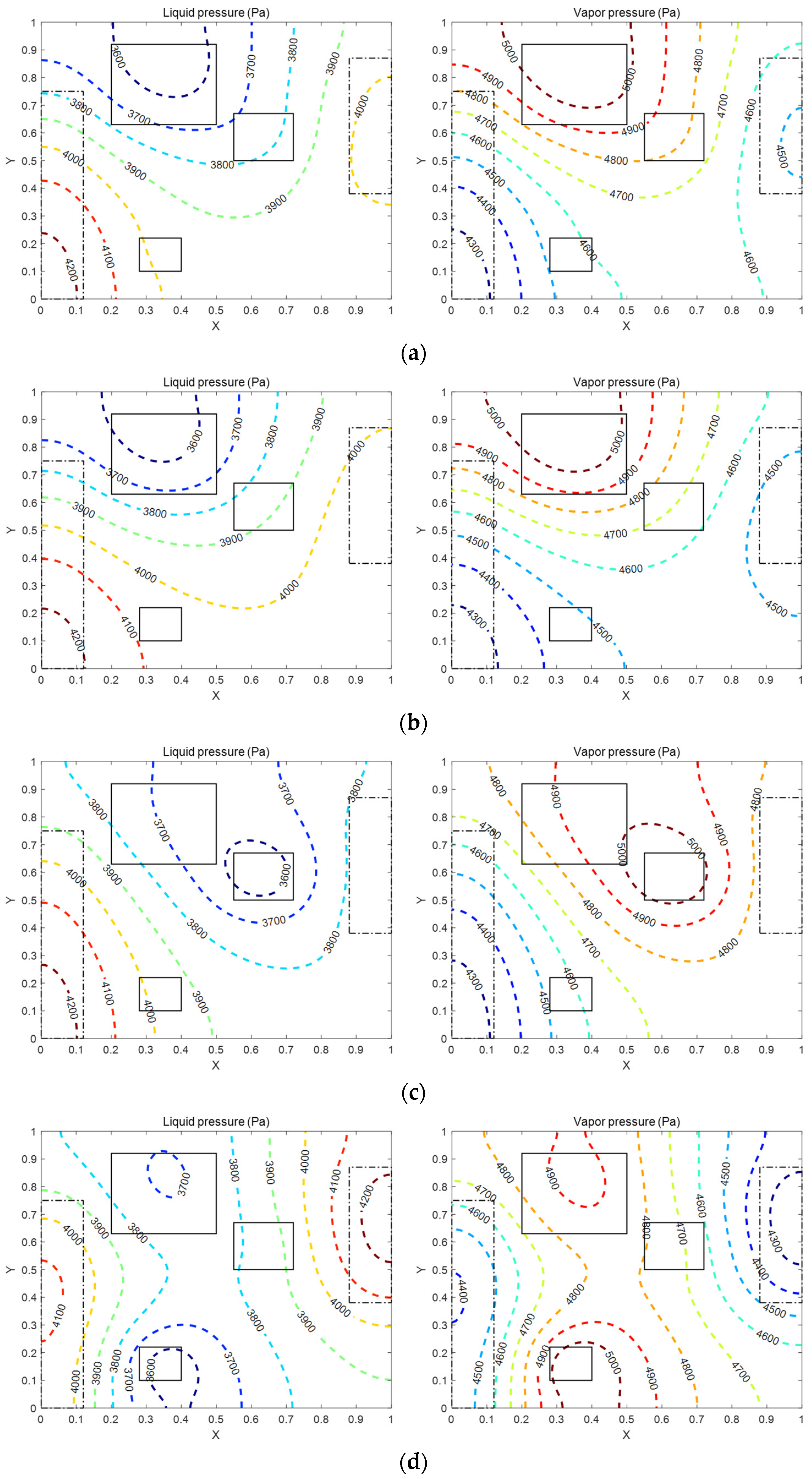
3.1. Flow Characteristics in Vapor Chamber under Different Heat Flux Conditions for Each Heat Source

The heat flux conditions of the multiple heat sources affect the pressure and temperature distributions, which in turn change the flow patterns of the working fluid in the TVC and influence the maximum heat transfer rate. Figure 4 shows the flow patterns of the liquid and vapor when only the different heat flux conditions are changed under the fixed wick type and geometries. As shown in Figure 4a–d, it is observed that the liquid moves from the heat sinks towards the heat sources, while the vapor moves in the opposite direction. Additionally, in Figure 4b–d where different heat fluxes are applied to the heat sources, it is observed that the velocity of the working fluid in heat sources where a higher heat flux is applied is a larger velocity than the other sources. The total input power of Figure 4a–d is the same as the maximum heat transfer rate, 50 W, 39.1 W, 48.6 W, and 77 W, respectively. Moreover, the pressure distributions of liquid and vapor are presented in Figure 5 under the same conditions as Figure 4. The total pressure drops in Figure 5a–d reach the capillary limit of 1539 Pa. Particularly, Figure 5d clearly shows that the isobaric lines of liquid and vapor become denser in the E3 region where the highest heat flux acts. Although the isobaric lines of liquid and vapor become denser in the E3 region, the mass flow rate evaporated in all heat sources under the fixed capillary limit in the case of E1:E2:E3 =1/10:1/10:8/10 that is larger than other cases.

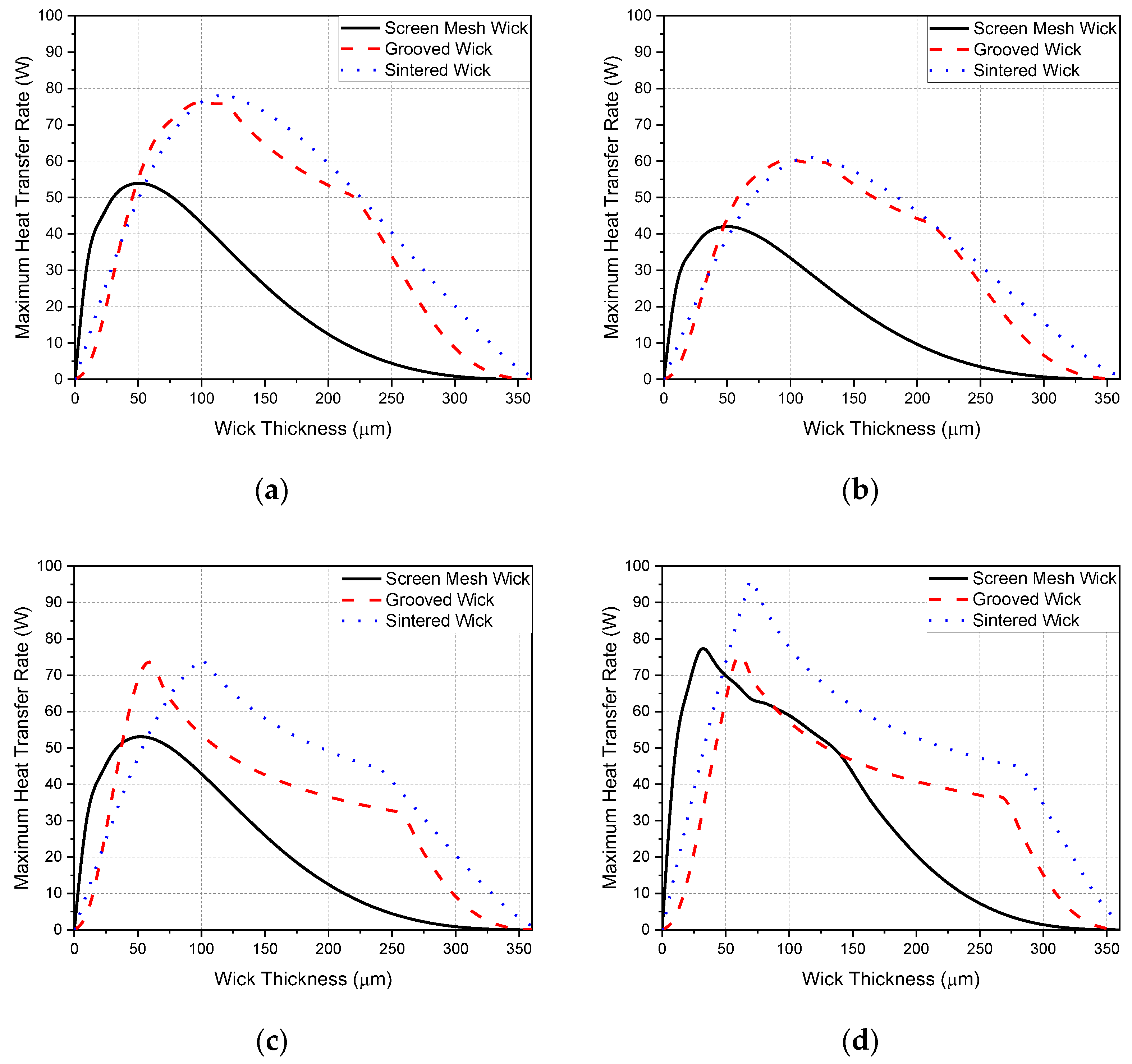
3.2. The Effect of Wick Type on the Maximum Heat Transfer Rate

The dimensions of the TVC, including the length in the x-direction, length in the y-direction, total height, and wall thickness, are 40 mm, 40 mm, 0.9 mm, and 265 μm, respectively.
The material of the wall and wick and the working fluid are copper and D.I. water, respectively. The saturation temperature is assumed to be 30 °C. The positions and sizes of the heat sources and heat sinks as shown in Figure 1 are consistent with those used by Lefevre and Lallemand [12] and Subedi et al. [13]. Other detailed specifications are described in Table 1. The capillary limitation and the maximum permissible temperature constraint (80 °C) are used to determine the maximum heat transfer rate. Under the fixed external shape of the TVC and the fixed total height, which are the combined height of the wick (Hw) and vapor core (Hv), the maximum heat transfer rate was presented according to the type of wick as well as the different heat flux condition of heat sources. Figure 6 shows the maximum heat transfer rate of TVCs with three different wick types using the various heat flux conditions ( E 1 : E 2 : E 3 ). Particularly, when the heat fluxes of the heat sources are uniform ( E 1 : E 2 : E 3 = 1/3:1/3:1/3), the highest maximum heat transfer rates of TVCs with the sintered wick, grooved wick, and screen mesh wick are 78.1 W, 76.3 W, and 53.9 W, respectively. However, when the heat flux of the heat sources is not uniformly distributed, it is evident that the maximum heat transfer rate varies between 60 W and 100 W, with the wick structure significantly influencing the maximum heat transfer rate. This result indicates that the maximum heat transfer rate of the TVC and the optimal wick may vary in the presence of differences in the heat flux generated from multiple heat sources. Moreover, as shown in Figure 6, in the range of thicknesses from 0 to less than 40 μm, it is shown that TVCs with screen mesh wicks exhibit the highest maximum heat transfer rates regardless of the heat flux ratio of the heat sources. This is because the screen mesh wick has higher permeability than other types of wicks, resulting in a significantly lower liquid pressure drop below a wick thickness of 40 μm, although the capillary limitation of the screen mesh wick is lower than that of the sintered wick. Also, when the wick thickness range is over 100 μm, the maximum heat transfer rate of the sintered wick is higher than that of other wick types regardless of the heat flux ratio of the heat sources. The reason can be explained as follows: as the wick thickness increases, among the factors determining the maximum heat transfer rate, the capillary force becomes more dominant than the pressure drop due to the permeability. This is because the pressure drop decreases dramatically with the increase in the cross-sectional area through which the liquid can move. The maximum heat transfer rate of a TVC with E1:E2:E3 = 1/10:1/10:8/10 is higher than that with E1:E2:E3 = 8/10:1/10:1/10 although the heat flux ratio of heat source E3 accounts for 8/10 of the total heat flux, which indicates that its heat flux density is the highest. The reason can be explained as follows: in Figure 6b, representing the heat flux condition of E1:E2:E3 = 8/10:1/10:1/10, the proportions of the heat load relative to the total heat load are 94%, 4%, and 2%, respectively. However, the proportions of the heat load relative to the total heat load in Figure 6d representing the heat flux condition E1:E2:E3 = 1/10:1/10:8/10 are 38%, 12%, and 50%, respectively. Despite the higher heat flux ratio of E3 in E1:E2:E3 = 1/10:1/10:8/10, the distribution of heat load among the three sources is more uniform. In addition, under the fixed capillary limitation, which is reached faster than the allowable maximum temperature constraint, the mass flow rate of working fluid in all heat sources when E1:E2:E3 = 1/10:1/10:8/10 is larger than other cases although the isobaric lines of liquid and vapor become denser in the E3 region, as shown in Figure 5. Consequently, the maximum heat transfer rate limited by capillary action increases, resulting in the highest maximum heat transfer rate achievable. In addition, as shown in Figure 6a–c, the maximum heat transfer rates for thin vapor chambers with screen mesh wicks consist of a single smooth curve according to the wick thickness because the maximum heat transfer rate was determined only by the capillary limit. However, the maximum heat transfer rate of the other cases has two peaks as the wick thickness increases. Between two peaks, for example, the grooved wick thickness of the grooved wick is between 60 μm and 260 μm, as shown in Figure 6c, and the maximum heat transfer amount is determined by the allowable maximum temperature constraint.

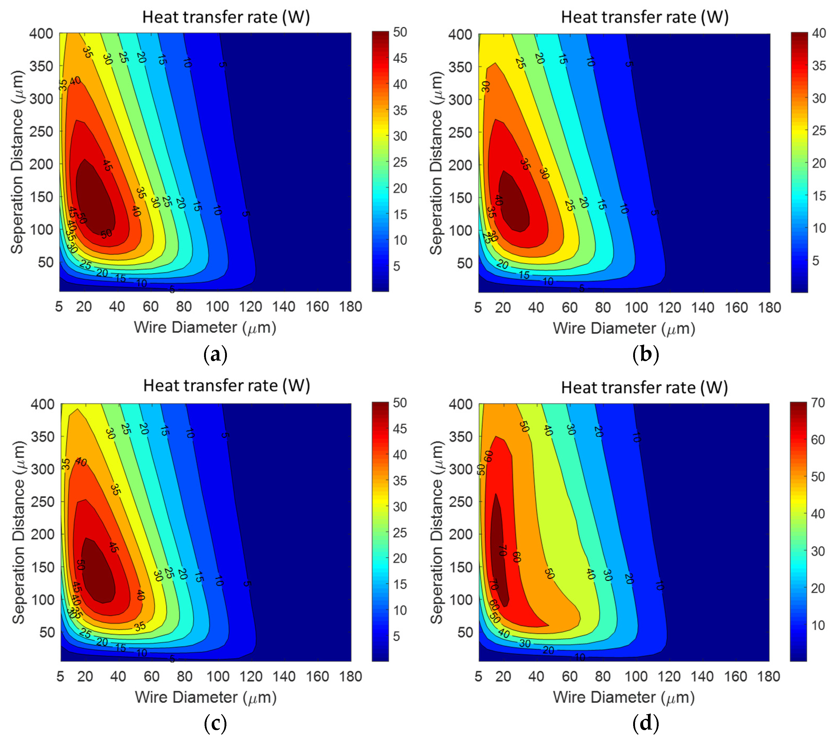
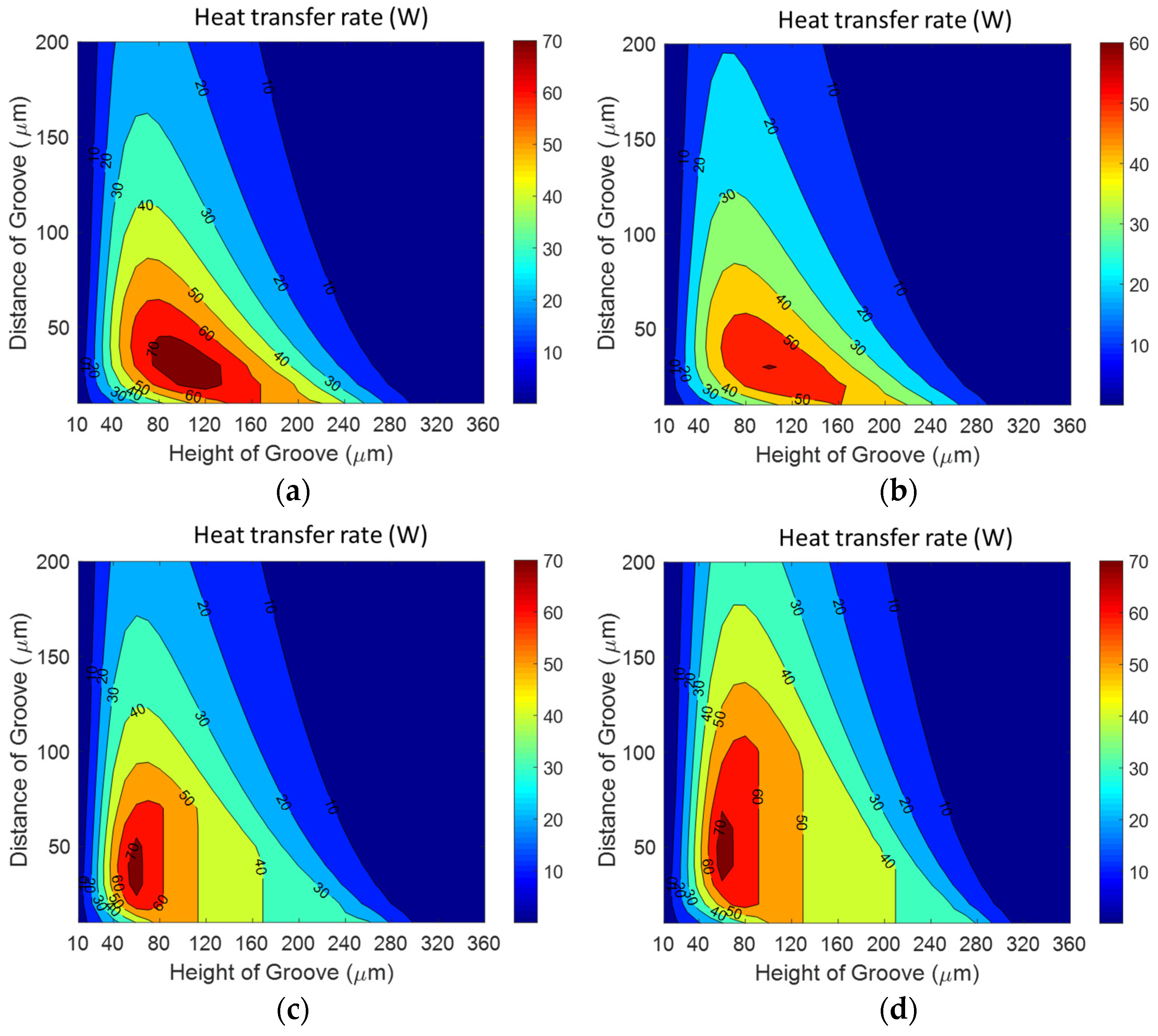
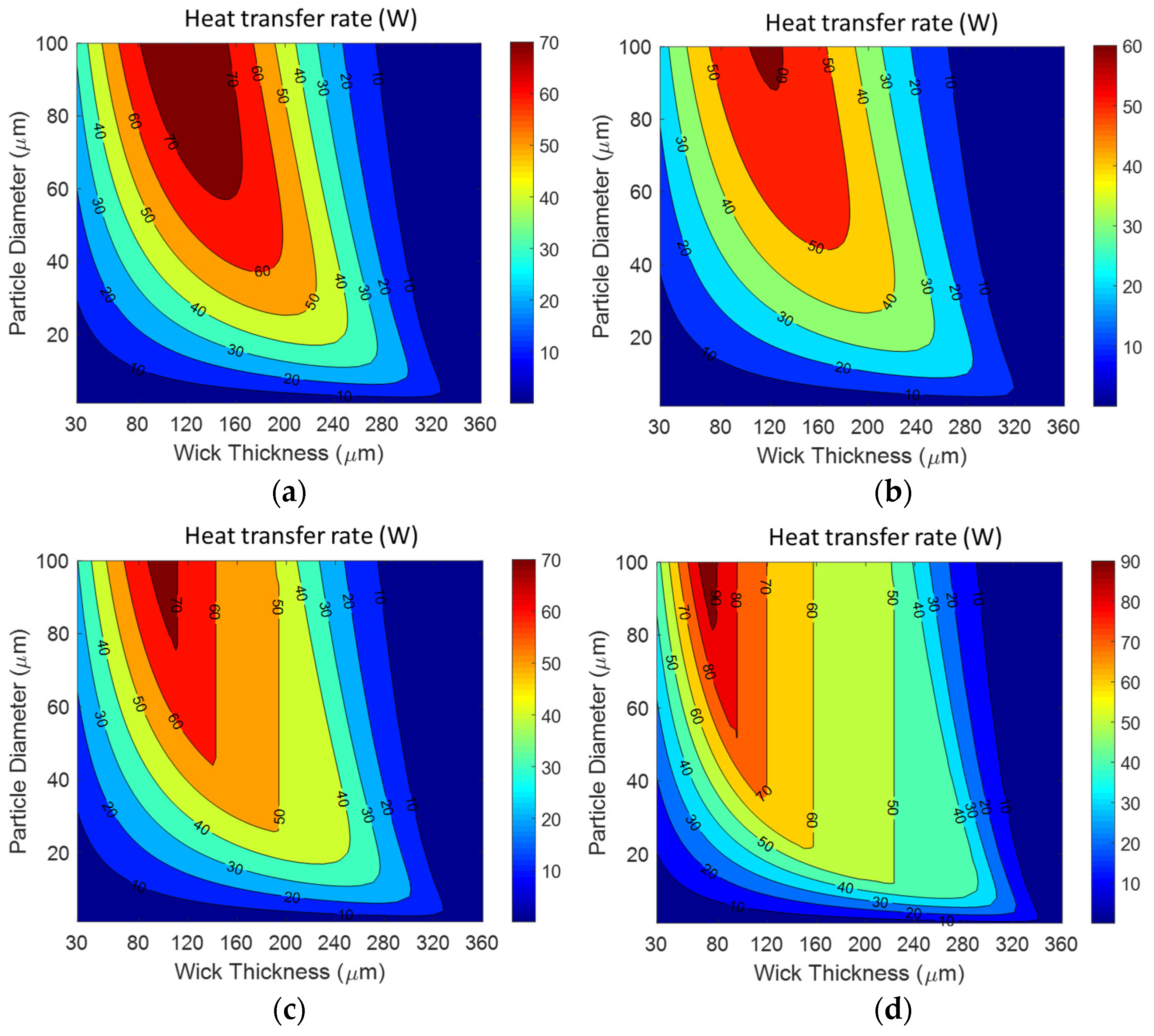
3.3. The Effects of Engineering Key Parameters on the Maximum Heat Transfer Rate

Three types of wicks are optimized to maximize the heat transfer rate using engineering key parameters. The optimization results for the screen mesh wick, grooved wick, and sintered wick under various heat flux conditions are shown in Figure 7, Figure 8 and Figure 9. Figure 7 shows the TVC with a screen mesh wick, characterized by a wire diameter and wire separation distance ranging from 20 to 40 μm and 100 to 200 μm, respectively, which can achieve the maximum heat transfer rate regardless of heat flux conditions. Also, Figure 8 presents the effects of the height and the distance of the groove on the heat transfer rate of the TVC with a grooved wick. The TVC exhibits the maximum heat transfer rates at a distance of the groove ranging from 30 to 50 μm and height ranging from 60 to 100 μm. Particularly, vertical contour lines as shown in Figure 8 appear when the maximum heat transfer rate is determined by the allowable maximum temperature constraint. Moreover, Figure 9 shows the effects of the particle diameter and wick thickness on the heat transfer rate when the sintered wick is used in a TVC. In the present study, the optimization was theoretically conducted by restricting the sintering particles to below 100 μm for a thin vapor chamber with a thickness of less than 1 mm. So, as shown in Figure 9, the maximum heat transfer rate for the sintered wick is observed when the particle diameter is in the range of 80~100 μm and the wick thickness is within 60~120 μm. As a result, it is shown that TVCs exhibit the maximum heat transfer rates in specific regions of engineering key parameters, irrespective of the distribution of heat flux.

4. Conclusions

In this paper, the modified analytical model was developed to predict the maximum heat transfer rate of the TVC with multiple heat sources and heat sinks considering different heat flux conditions for each heat source. The model was validated by previous results [12]. With the modified analytical model, it was shown that the heat flux conditions of multiple heat sources affect the pressure and temperature distributions, which in turn change the flow patterns of the working fluid in the TVC and influence the maximum heat transfer rate. The key engineering parameters affecting the maximum heat transfer for screen mesh, grooved, and sintered wicks were theoretically identified, with two variables each. The effects of the parameters on the maximum heat transfer rate under various heat flux conditions were presented. Particularly, we observed that the maximum heat transfer rate of screen mesh wicks can be higher when the wick thickness is below 40 μm regardless of the heat flux ratio of the heat sources, although sintered wicks are generally known to have better heat transfer performance than other wick types. Moreover, it was shown that the sintered wick exhibited the highest maximum heat transfer rate when the wick thickness exceeded 100 μm regardless of the heat flux ratio of the heat sources. The results showed that the maximum heat transfer rate of the vapor chamber in the specific ranges of wick thickness is strongly affected by the geometric parameters of the wick rather than by the different heat flux distributions. Finally, it was shown that three types of wicks were optimized to maximize the heat transfer rate using two engineering key parameters. Using the model presented in this paper, which considers multiple heat sources under different heat flux conditions, it is expected that the optimal heat flux ratio to maximize the maximum heat transfer rate can be determined. Additionally, it is anticipated that the positions of heat sources can be optimized for a fixed different heat flux condition.

Author Contributions

Conceptualization, S.H.K. and S.P.J.; methodology, S.H.K.; software, S.H.K.; validation, S.H.K. and S.P.J.; formal analysis, S.H.K. and S.P.J.; investigation, S.Y.K. and S.J.P.; data curation, S.H.K.; writing—original draft preparation, S.H.K.; writing—review and editing, S.P.J., S.Y.K. and S.J.P.; supervision, S.P.J.; project administration, S.P.J. All authors have read and agreed to the published version of the manuscript.

Funding

This research received no external funding.

Data Availability Statement

Data available on request due to restrictions e.g., privacy or ethical.

Acknowledgments

This work was supported by the 2021 Korea Aerospace University Faculty Research grant and partially supported by the National Research Foundation of Korea (NRF) grant funded by the Korea government (MSIT). (No. NRF-2022R1A2C1009997).

Conflicts of Interest

The authors declare no conflicts of interest.

Nomenclature

a, b, cTVC dimensions [m]
Atotal area [m2]
Am0, A0n, AmnFourier coefficients of temperature
BiBiot number (hc/kwall)
Bm0, B0n, BmnFourier coefficients of heat flux
Cm0, C0n, CmnFourier coefficients of pressure
Cpspecific heat [J·kg−1K−1]
dwire diameter [m]
dgdistance of groove [m]
Ddiameter of particle [m]
Dhhydraulic diameter [m]
D*effective diameter of particle [m]
f RePoiseuille number
hequivalent heat transfer coefficient [W·m−2K−1]
hlvlatent heat of vaporization [J·kg−1]
Hthickness or height [m]
kwallthermal conductivity [W·m−1K−1]
Kpermeability [m2]
npnumber of particles
Nmesh number
Ppressure [Pa]
Qheat transfer rate [W]
rpore radius [m]
Ttemperature [K]
T*dimensionless temperature
uvelocity [m·s−1]
Vvolume [m3]
wseparation distance of wires [m]
wfgroove width [m]
x, y, zcoordinates [m]
X, Y, Zdimensionless coordinates
Greek Symbols
αoverlap ratio of particles
β, γdimensionless lengths
εporosity
ηratio of the heat source area to the heat sink area
θcontact angle
κweighting factor
μdynamic viscosity [kg·m−1s−1]
ρdensity [kg·m−3]
σsurface tension [N·m−1]
φheat flux [W·m−2]
ϕdimensionless heat flux
ωliquid pressure drop coefficient by no-slip condition
Subscripts
bbond
ccondenser
capcapillary
eevaporator
effeffective
ggroove
lliquid
oimposed
pparticle
satsaturation
vvapor
wwick

References

  1. Ramadass, P.; Haran, B.; White, R.; Popov, B.N. Capacity fade of Sony 18650 cells cycled at elevated temperatures: Part I. Cycling performance. J. Power Sources 2002, 112, 606–613. [Google Scholar] [CrossRef]
  2. Bodenes, L.; Naturel, R.; Martinez, H.; Dedryvère, R.; Menetrier, M.; Croguennec, L.; Pérès, J.P.; Tessier, C.; Fischer, F. Lithium secondary batteries working at very high temperature: Capacity fade and understanding of aging mechanisms. J. Power Sources 2013, 236, 265–275. [Google Scholar] [CrossRef]
  3. Gurrum, S.P.; Edwards, D.R.; MarchandGolder, T.; Akiyama, J.; Yokoya, S.; Drouard, J.; Dahan, F. Generic thermal analysis for phone and tablet systems. In Proceedings of the 2012 IEEE 62nd Electronic Components and Technology Conference, San Diego, CA, USA, 29 May–1 June 2012. [Google Scholar]
  4. Kwon, H.K.; Hwang, J.; Chung, H.; Kang, M.; Cho, H.D.; Kim, Y.M. Thermal Power of Mobile Application Processor. Int. Symp. Microelectron. 2012, 1, 000866–000872. [Google Scholar] [CrossRef]
  5. Ahamed, M.S.; Saito, Y.; Mashiko, K.; Mochizuki, M. Characterization of a high performance ultra-thin heat pipe cooling module for mobile handheld electronic devices. Heat Mass Transf. 2017, 53, 3241–3247. [Google Scholar] [CrossRef]
  6. Choi, W.; Kang, M.; Han, S. Analysis of thermal characteristics of a battery module using a novel graphite material. In Proceedings of the 2019 IEEE Transportation Electrification Conference and Expo, Asia-Pacific, Seogwipo-si, Republic of Korea, 8–11 May 2019. [Google Scholar]
  7. Li, J.; Lv, L.; Zhou, G.; Li, X. Mechanism of a microscale flat plate heat pipe with extremely high nominal thermal conductivity for cooling high-end smartphone chips. Energy Convers. Manag. 2019, 201, 112202. [Google Scholar] [CrossRef]
  8. Huang, G.; Liu, W.; Luo, Y.; Deng, T.; Li, Y.; Chen, H. Research and optimization design of limited internal cavity of ultra-thin vapor chamber. Int. J. Heat Mass Transf. 2020, 148, 119101. [Google Scholar] [CrossRef]
  9. Li, B.; Yin, X.; Tang, W.; Zhang, J. Optimization design of grooved evaporator wick structures in vapor chamber heat spreaders. Appl. Therm. Eng. 2020, 166, 114657. [Google Scholar] [CrossRef]
  10. Ranjan, R.; Murthy, J.Y.; Garimella, S.V.; Altman, D.H.; North, M.T. Modeling and design optimization of ultrathin vapor chambers for high heat flux applications. IEEE Trans. Compon. Packag. Manuf. Technol. 2012, 2, 1465–1479. [Google Scholar] [CrossRef]
  11. Li, D.; Huang, Z.; Zhao, J.; Jian, Q.; Chen, Y. Analysis of heat transfer performance and vapor–liquid meniscus shape of ultra-thin vapor chamber with supporting columns. Appl. Therm. Eng. 2021, 193, 117001. [Google Scholar] [CrossRef]
  12. Lefevre, F.; Lallemand, M. Coupled thermal and hydrodynamic models of flat micro heat pipes for the cooling of multiple electronic components. Int. J. Heat Mass Transf. 2006, 49, 1375–1383. [Google Scholar] [CrossRef]
  13. Subedi, B.; Kim, S.H.; Jang, S.P. Effect of mesh wick geometry on the maximum heat transfer rate of flat-micro heat pipes with multiple heat sources and sinks. Int. J. Heat Mass Transf. 2019, 131, 537–545. [Google Scholar] [CrossRef] [PubMed]
  14. Kim, S.J.; Seo, J.K.; Do, K.H. Analytical and experimental investigation on the operational characteristics and the thermal optimization of a miniature heat pipe with a grooved wick structure. Int. J. Heat Mass Transfer. 2003, 46, 2051–2063. [Google Scholar] [CrossRef]
  15. Khrustalev, D.; Faghri, A. Thermal analysis of a micro heat pipe. ASME J. Heat Transf. 1994, 116, 189–198. [Google Scholar] [CrossRef]
  16. Kim, S.B.; Kim, K.H.; Jang, S.P.; Kedzierski, M.A. Thermal characteristics of silicon wafer-based TVCs (thin vapor chambers) with disk-shape using DI water. Int. J. Heat Mass Transf. 2018, 127, 526–534. [Google Scholar] [CrossRef]
  17. Faghri, A. Heat Pipe Science and Technology, 1st ed.; Taylor & Francis: Washington, DC, USA, 1995. [Google Scholar]
  18. Kakaç, S.; Shah, R.K.; Aung, W. Handbook of Single-Phase Convective Heat Transfer; John-Wiley Sons: New York, NY, USA, 1987. [Google Scholar]
  19. Revellin, R.; Rulliere, R.; Lefèvre, F.; Bonjour, J. Experimental validation of an analytical model for predicting the thermal and hydrodynamic capabilities of flat micro heat pipes. Appl. Therm. Eng. 2009, 29, 1114–1122. [Google Scholar] [CrossRef]
  20. Kaviany, M. Principles of Heat Transfer in Porous Media; Springer: New York, NY, USA, 1995. [Google Scholar]
  21. Chi, S.W. Heat Pipe Theory and Practice: A Sourcebook; Hemisphere Pub.: Washington, DC, USA, 1976. [Google Scholar]
  22. Slobozhanin, L.A.; Alexander, J.I.D.; Collicott, S.H.; Gonzalez, S.R. Capillary pressure of a liquid in a layer of close-packed uniform spheres. Phys. Fluids 2006, 18, 082104. [Google Scholar] [CrossRef]
  23. Byon, C.; Kim, S.J. Capillary performance of bi-porous sintered metal wicks. Int. J. Heat Mass Transf. 2012, 55, 4096–4103. [Google Scholar] [CrossRef]
  24. Qu, Y.; Zhou, K.; Zhang, K.F.; Tian, Y. Effects of multiple sintering parameters on the thermal performance of bi-porous nickel wicks in Loop Heat Pipes. Int. J. Heat Mass Transf. 2016, 99, 638–646. [Google Scholar] [CrossRef]
  25. Xiao, B.; Faghri, A. A three-dimensional thermal-fluid analysis of flat heat pipes. Int. J. Heat Mass Transf. 2008, 51, 3113–3126. [Google Scholar] [CrossRef]
  26. Weibel, J.A.; Garimella, S.V. Visualization of vapor formation regimes during capillary-fed boiling in sintered-powder heat pipe wicks. Int. J. Heat Mass Transf. 2012, 55, 3498–3510. [Google Scholar] [CrossRef]
  27. Byon, C.; Kim, S.J. Effects of geometrical parameters on the boiling limit of bi-porous wicks. Int. J. Heat Mass Transf. 2012, 55, 7884–7891. [Google Scholar] [CrossRef]
  28. Hong, F.J.; Cheng, P.; Wu, H.Y.; Sun, Z. Evaporation/boiling heat transfer on capillary feed copper particle sintered porous wick at reduced pressure. Int. J. Heat Mass Transf. 2013, 63, 389–400. [Google Scholar] [CrossRef]
  29. Li, Y.; Li, Z.; Zhou, W.; Zeng, Z.; Yan, Y.; Li, B. Experimental investigation of vapor chambers with different wick structures at various parameters. Exp. Therm. Fluid Sci. 2016, 77, 132–143. [Google Scholar] [CrossRef]
  30. Deng, D.; Huang, Q.; Xie, Y.; Huang, X.; Chu, X. Thermal performance of composite porous vapor chambers with uniform radial grooves. Appl. Therm. Eng. 2017, 125, 1334–1344. [Google Scholar] [CrossRef]
  31. Zhang, S.; Chen, C.; Chen, G.; Sun, Y.; Tang, Y.; Wang, Z. Capillary performance characterization of porous sintered stainless steel powder wicks for stainless steel heat pipes. Int. Commun. Heat Mass Transf. 2020, 116, 104702. [Google Scholar] [CrossRef]
Figure 1. A schematic view of a thin vapor chamber (TVC). (a) Isometric view, (b) side view.
Energies 17 03330 g001
Figure 2. Schematic of wick structures. (a) Screen mesh wick, (b) grooved wick, (c) simple cube for sintered wick.
Energies 17 03330 g002
Figure 3. Validation results (Q = 76.6 W, Tsat = 50 °C). (a) Temperature difference, (b) the liquid pressure distribution of a TVC wall, (c) vapor pressure distribution.
Energies 17 03330 g003
Figure 4. Velocity distribution in TVCs with screen mesh wick according to heat flux ratio of heat sources (d = 15 μm, w = 170 μm, Hw = 30 μm, Q = Qmax). (a) E 1 : E 2 : E 3 = 1/3:1/3:1/3, (b) E 1 : E 2 : E 3 = 8/10:1/10:1/10, (c) E 1 : E 2 : E 3 = 1/10:8/10:1/10, (d) E 1 : E 2 : E 3 = 1/10:1/10:8/10.
Energies 17 03330 g004
Figure 5. Pressure distribution in TVCs with screen mesh wick according to heat flux ratio of heat sources. (d =15 μm, w = 170 μm, Hw = 30 μm, Q = Qmax) (a) E 1 : E 2 : E 3 = 1/3:1/3:1/3, (b) E 1 : E 2 : E 3 = 8/10:1/10:1/10, (c) E 1 : E 2 : E 3 = 1/10:8/10:1/10, (d) E 1 : E 2 : E 3 = 1/10:1/10:8/10.
Energies 17 03330 g005
Figure 6. The maximum heat transfer rate of TVCs with three types of wicks according to the heat flux ratio of the heat sources (a) E 1 : E 2 : E 3 = 1/3:1/3:1/3, (b) E 1 : E 2 : E 3 = 8/10:1/10:1/10, (c) E 1 : E 2 : E 3 = 1/10:8/10:1/10, (d) E 1 : E 2 : E 3 = 1/10:1/10:8/10.
Energies 17 03330 g006
Figure 7. Heat transfer rate for screen mesh wick according to heat flux ratio of heat sources. (a) E 1 : E 2 : E 3 = 1/3:1/3:1/3, (b) E 1 : E 2 : E 3 = 8/10:1/10:1/10, (c) E 1 : E 2 : E 3 = 1/10:8/10:1/10, (d) E 1 : E 2 : E 3 = 1/10: 1/10: 8/10.
Energies 17 03330 g007
Figure 8. Heat transfer rate for grooved wick according to heat flux ratio of heat sources. (a) E 1 : E 2 : E 3 = 1/3:1/3:1/3, (b) E 1 : E 2 : E 3 = 8/10:1/10:1/10, (c) E 1 : E 2 : E 3 = 1/10:8/10:1/10, (d) E 1 : E 2 : E 3 = 1/10:1/10:8/10.
Energies 17 03330 g008
Figure 9. Heat transfer rate for sintered wick according to heat flux ratio of heat sources. (a) E 1 : E 2 : E 3 = 1/3:1/3:1/3, (b) E 1 : E 2 : E 3 = 8/10:1/10:1/10, (c) E 1 : E 2 : E 3 = 1/10:8/10:1/10, (d) E 1 : E 2 : E 3 = 1/10:1/10:8/10.
Energies 17 03330 g009
Table 1. The specifications of the TVC (thin vapor chamber).
ParametersSpecification
Vapor chamber length (a)40 mm
Vapor chamber breadth (b)40 mm
Height of wall (c)265 µm
Total height (Hw + Hv)370 µm
Wick materialCopper
Working fluidD.I. water
Saturation temperature (Tsat)30 °C
Position of heat source 1 (E1)0.25 ≤ x/a ≤ 0.4, 0.65 ≤ y/b ≤ 0.8
Position of heat source 2 (E2)0.6 ≤ x/a ≤ 0.75, 0.55 ≤ y/b ≤ 0.7
Position of heat source 3 (E3)0.25 ≤ x/a ≤ 0.4, 0.2 ≤ y/b ≤ 0.35
Position of heat sink 1 (C1)0 ≤ x/a ≤ 0.1, 0 ≤ y/b ≤ 1
Position of heat sink 2 (C2)0.9 ≤ x/a ≤ 1, 0 ≤ y/b ≤ 1
Screen mesh wick
Wire diameter (d)5–180 µm
Wire separation distance (w)5–400 µm
Wick thickness (Hw)10–360 µm
Grooved wick
Fin width (wf)4–86 µm
Groove height (Hg)10–360 µm
Groove distance (dg)5–200 µm
Sintered wick
Particle diameter (D)1–100 µm
Wick thickness (Hw)30–360 µm
Overlap ratio of particles (α)0.025
Disclaimer/Publisher’s Note: The statements, opinions and data contained in all publications are solely those of the individual author(s) and contributor(s) and not of MDPI and/or the editor(s). MDPI and/or the editor(s) disclaim responsibility for any injury to people or property resulting from any ideas, methods, instructions or products referred to in the content.

