
Recent Advances in Geochemical and Mineralogical Studies on CO2–Brine–Rock Interaction for CO2 Sequestration: Laboratory and Simulation Studies


Abstract
:1. Introduction
2. Mechanisms for CO2–Brine–Rock Interactions
- The rapid dissolution of carbonates can lead to the degradation of caprocks, wellbores, and fault seals, potentially allowing CO2 to migrate into overlying formations and cause equipment leakage [31].
- Carbonate precipitation in caprocks can lower the permeability, stabilizing storage.
- Mineral dissolution or precipitation in reservoirs may change permeability, affecting the flow of CO2 and CO2-saturated brine.
2.1. MPD (Mineralization, Precipitation, and Dissolution)
2.2. Advancements in Visualization through CT Scanners and In Situ Techniques
- Figure 17a: Different dissolution patterns based on varying Péclet and Damköhler numbers.
- Figure 17b: The dissolution front remains highly stable for small Péclet numbers (Pé ≤ 10−2) and Da1 > 1.
- Figure 17c: When Da1 > 1 and injection rates are higher but within a diffusion-dominated transport regime (1 ≥ Pé > 10−2), the dissolution front becomes non-uniform along the vertical cross-section, forming a conical pattern due to the faster regions dragging the dissolution.
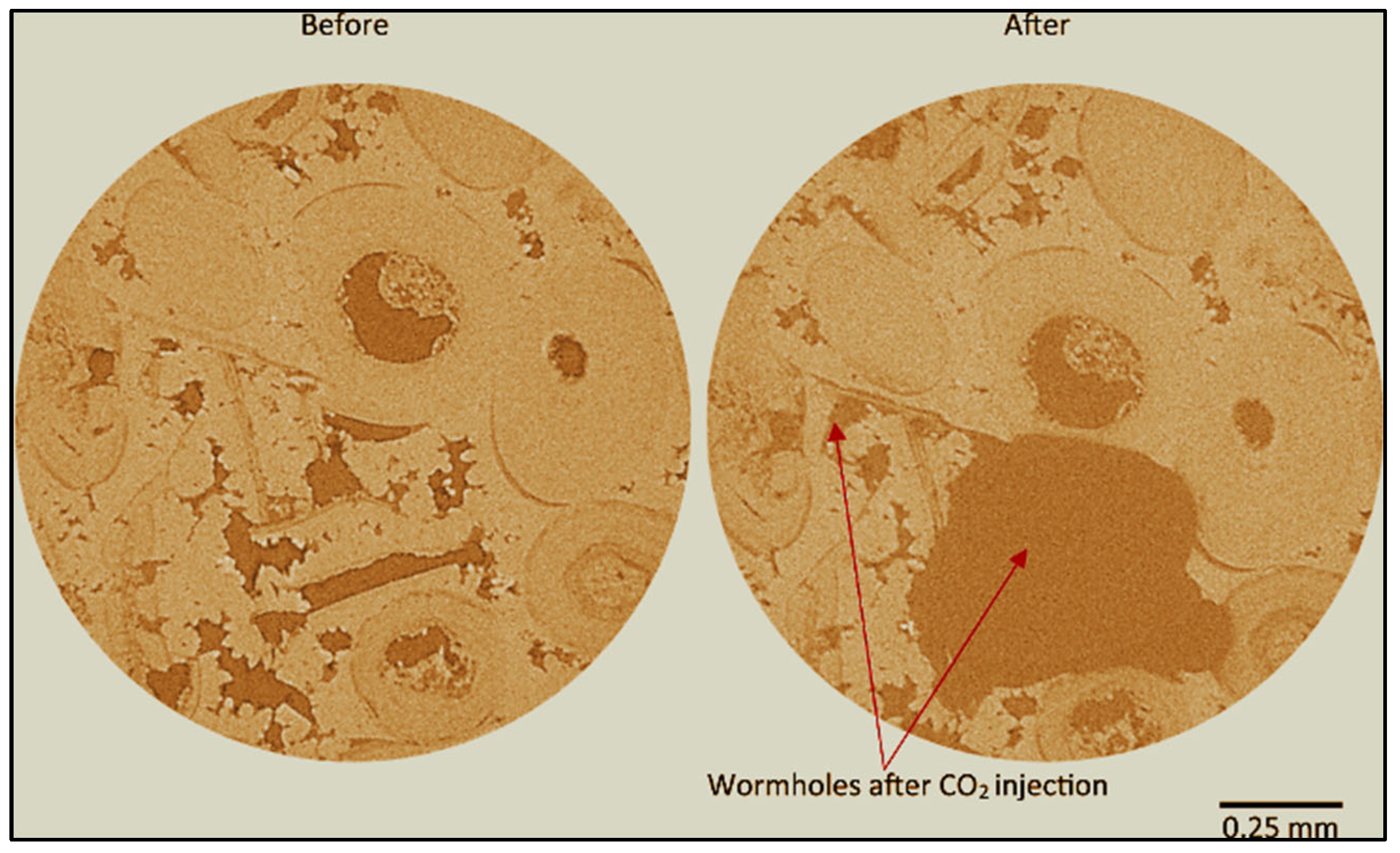
- Figure 17d: A single dominant wormhole forms for conditions where Da1 > 1 and 10 ≥ Pé > 1. In this case, advection dominates the void space due to the acid transport mechanism.
3. Laboratory Studies of CO2–Brine–Rock Interaction for Carbon Storage
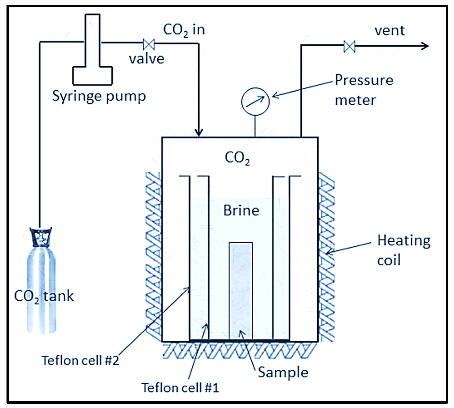
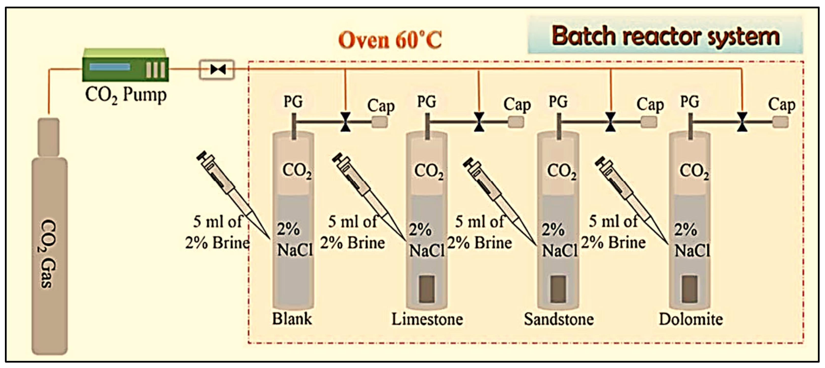
3.1. Laboratory-Scale Static Batch Reactor Experiments of CO2–Brine–Rock Interaction for Carbon Storage
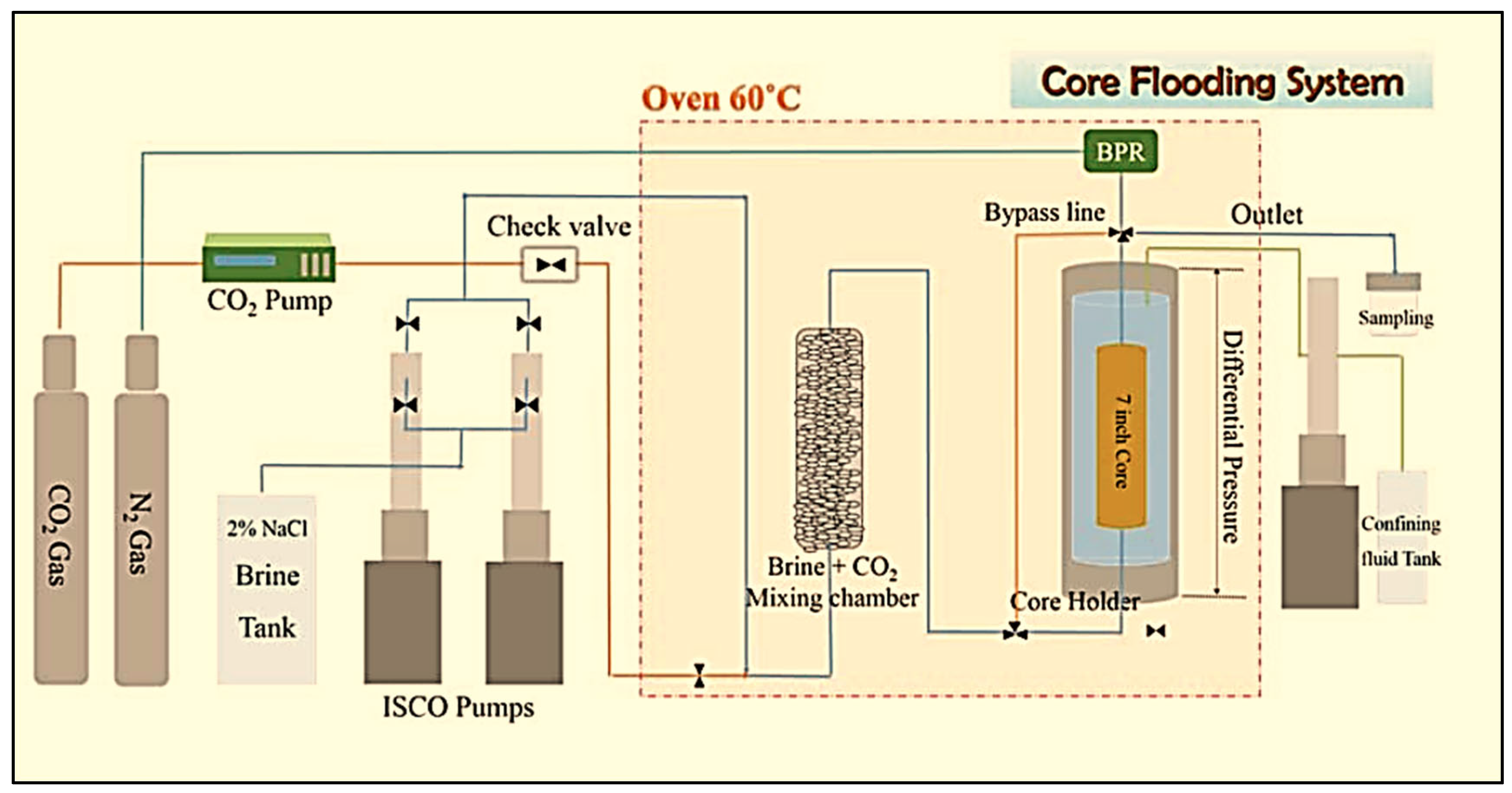
3.2. Laboratory-Scale Core Flooding Experiments of CO2–Brine–Rock Interaction for Carbon Storage
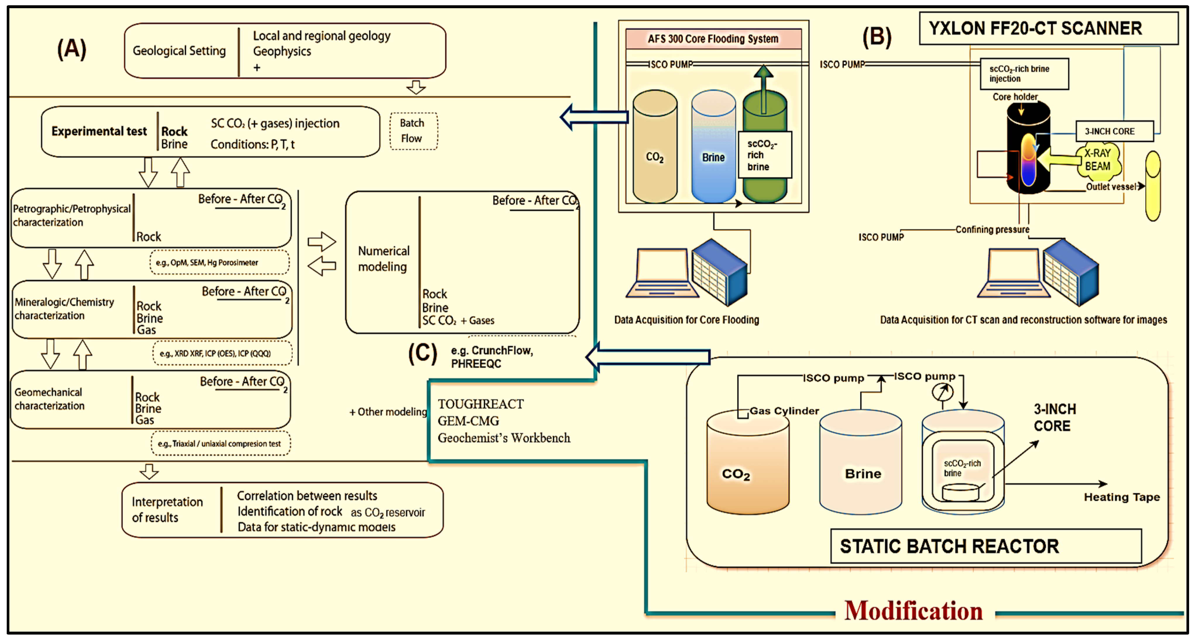
- (1)
- Petrophysical characterization involving helium porosimeter and ultra-permeability assessments.
- (2)
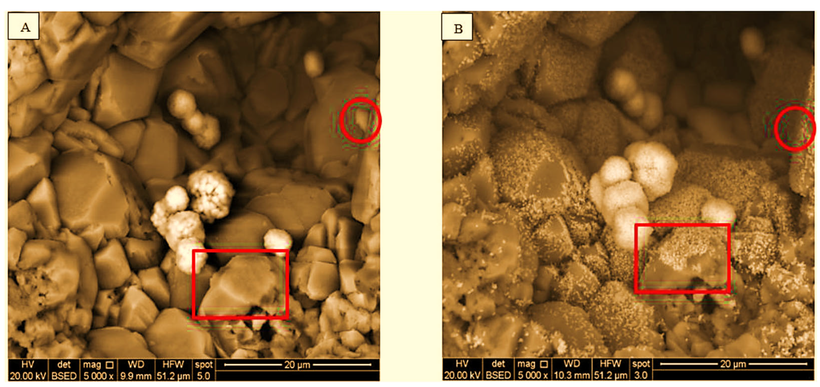
- Analytical chemistry processes, including XRD and SEM.
- (3)
- Utilization of a static batch reactor for investigating long-term CO2 storage.
- (4)
- AFS 300 core flooding experiments to observe chemical changes using the Comet Yxlon FF20 industrial CT scanner.
- (5)
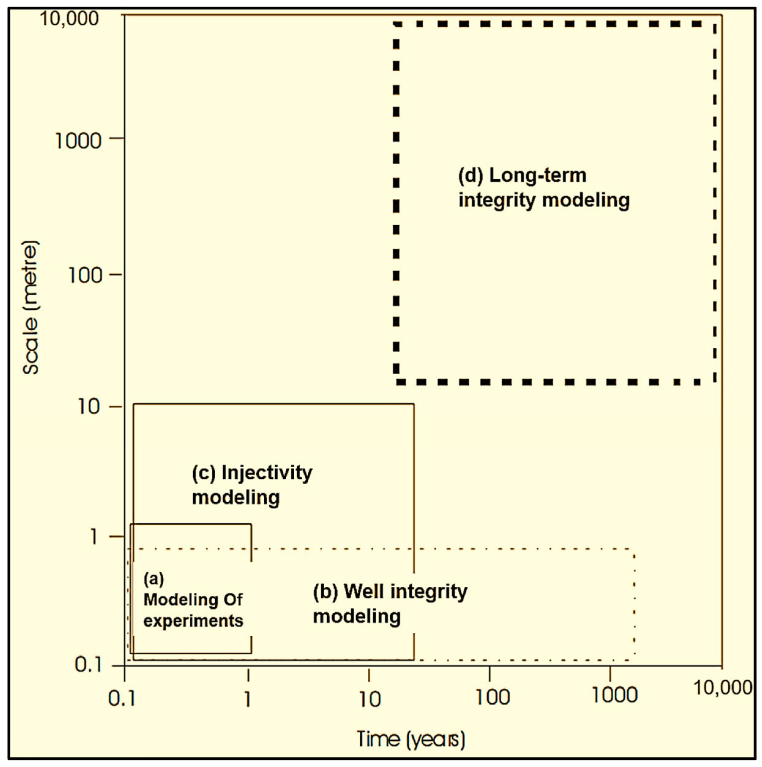
- Implementing reactive transport modeling to explore long-term CO2 storage dynamics over 1 to 10,000 years using simulation, elucidating the processes governing long-term storage and sequestration integrity.
4. Simulation Studies of CO2–Brine–Rock Interaction for Carbon Storage

| Simulators | Comparative Overview |
|---|---|
| TOUGHREACT V4.13-OMP [94] |
|
| Geochemist’s Workbench (GWB 2023) [95,96] |
|
| PHREEQC (V3) [97] |
|
| CRUNCHFLOW (2009) [98] |
|
| GEM-CMG (2023.40) |
|
| Sample | Simulator | Research Findings |
|---|---|---|
| Sandstone and Limestone [100] | Numerical simulation (GEM module of CMG) | Geochemical activity significantly impacts limestone, causing a 16.12% increase in porosity. Due to chemical activity, both limestone and sandstone experience decreased reservoir strength during the injection period. The maximum subsidence after 500 years is 0.0017 m in sandstone and 0.033 m in limestone, attributed to geochemical activities. |
| Sand and Shale [101] | 2D radial reservoir model for two-phase flow (TOUGHREACT) | Following 10,000 years, 95% of the CO2 dissolves in the brine, while minerals absorb 5%. The mineralogy of the sand and shale is comprehensively characterized utilizing kinetics based on transition state theory. |
| Carbonate Rock [102] | GEM-GHG [103,104] | After 10,000 years, the percentage of CO2 trapped in minerals ranges from 40% to 100%, depending on the initial mineralogy. The rock mineralogy is determined using kinetics based on transition state theory. |
| Cap Rock [105] | PHREEQC (V2.6) | The alteration in porosity in the cap rock is insignificant, with a minor reduction in φ being modeled overall, except at the interface between the reservoir and cap rock after 3000 years. The entire cap rock mineralogy is assessed using kinetics based on transition state theory reactions. |
| Lithic Sandstone and Calcareous Mudstone (deep coal seams) [106] | TOUGHREACT | Geochemical simulation can partially reflect the dissolution and precipitation state of minerals, but it only partially aligns with experimental results. Ensuring reliability requires incorporating the actual formation’s physical properties and the rocks’ thermodynamic parameters into the simulation. |
| Calcite [34] | PHREEQC (V3) | This study investigated the geochemical perspective of CO2/calcite/brine wettability, considering pressure, temperature, and salinity effects through surface complexation modeling. The findings indicate that pressure, temperature, and salinity influence calcite surface species concentrations, surface potential, and disjoining pressure, impacting CO2-wetness and water-wetness dynamics. |
| Eagle Ford and Mancos Shales [107] | PHREEQC (V3) | A one-dimensional reactive transport model using PHREEQC simulated CO2–shale interaction. Equilibrium and kinetic models at 70 °C and 117 atm, calibrated with shale core data from Eagle Ford and Mancos fields, revealed CO2 injection triggering mineral dissolution and precipitation. The models emphasized the effectiveness of mineral trapping and significant changes occurring between 10 and 100 years. The results contribute to understanding the mineral evolution in CO2–shale interaction, but further studies are needed to address field-scale uncertainties. |
| Shihezi Formation [108] | TOUGHREACT V4.12-OMP (10, 20, 30, 300, 500 and 1000 years) | Numerical simulations of CO2–brine–rock interactions in the Shihezi Formation indicate K-feldspar and albite dissolution, while calcite and quartz show dissolution and precipitation patterns. Despite a low interaction rate, this proves an ideal geological storage mechanism, influencing petrophysical parameters, minimizing leakage risk, and enhancing CO2 mineralization. |
| Carbonate [109] | PHREEQC (V3) | This study utilized experiments that included dynamics and static and PHREEQC geochemical modeling to analyze CO2–brine–rock interaction in carbonate rocks. The findings revealed intensified CO2 dissolution, pressure-independent surface CO2 loading on calcite and dolomite, and minimal influence exchange of ions on CO2 storage in these minerals. |
| Gabbro-Anorthosite [110] | CRUNCHFLOW (2009) | In laboratory experiments on a gabbro-anorthosite sample, the potential for CO2 mineral carbonation was assessed under realistic pressure and temperature conditions using seawater. Geochemical modeling in CrunchFlow successfully replicated the experimental observations, revealing increased iron, magnesium, and calcium concentrations during dissolution (Stage I) and signs of carbonation during subsaturation (Stage II). The study suggests mineral carbonation potential in the Torrão–Odivelas Massif, emphasizing further research to upscale the findings to field scale for effective CO2 emissions reduction. |
| Shale [111] | Geochemist’s Workbench | Geochemical modeling provides calcite dissolution, an increase in shale porosity because of overall shale brine CO2 interaction, and a pH drop due to desorption of tracer elements, and calcite is the main factor in controlling the mobilization of trace elements. |
5. Discussion
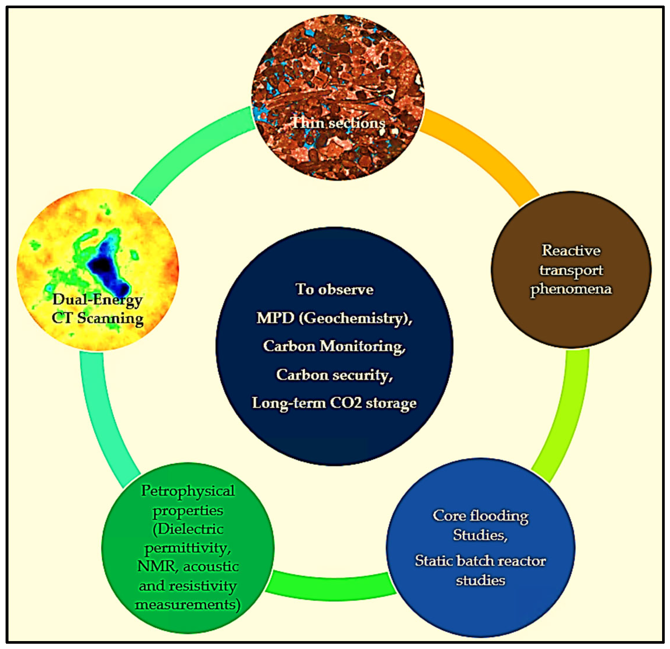
- Dual-energy CT scanning.
- Thin sections.
- Core flooding and batch reactor experiments.
- Petrophysical properties include dielectric permittivity, NMR measurements, and acoustic and resistivity measurements.
- Reactive transport phenomena modeling.
6. Conclusions
- CO2–Brine–Rock interactions can create MPD (mineralization, precipitation, dissolution), permeability, and porosity changes based on the types of reservoir rocks and effects on the reactive transport phenomena for long-term CO2 storage.
- Researchers used various simulators for geochemical reactions, including TOUGHREACT, PHREEQC, CRUNCHFLOW, and the GEM module of CMG. While the Geochemist’s Workbench is an exemplary interface for CO2 sequestration, it must be utilized more systematically. Geochemist’s Workbench is recommended to comprehensively understand CO2 storage over different time scales (e.g., 10, 20, 30, and up to 10,000 years), considering MPD, multiphase flow, permeability, porosity, changes, and reactive transport mechanisms.
- Rapid carbonate dissolution can corrode caprock, compromise fault seals, lead to equipment leakage, and affect CO2 security.
- Limited research has utilized industrial/micro-CT scanners. We can examine MPD interactions between CO2, brine, and rock for short- and long-term CO2 storage by employing industrial/micro-CT scanners with dual-energy techniques and analyzing cuttings or chips using micro-CT scanners.
- The effects of pressure, temperature, and salinity on CO2–brine–rock wettability and interfacial tension for long-term CO2 storage outcomes are unclear, including laboratory studies such as dynamic core flooding, static batch reactor experiments, and simulation studies, such as geochemical reactive transport modeling.
- Lab studies show that after CO2 storage, there is a reduction in permeability and porosity in fractured reservoirs [112]. This indicates the potential applicability of CO2 storage in fractured shale and limestone reservoirs. The chemical reactions play a crucial role in sealing fractures by reducing permeability. Further studies are required, and the topic’s applicability may extend to the Permian Basin for more CO2 storage security, monitoring, and integrity. Abel [113] estimated significant carbon sequestration capacities in the Permian Basin of west Texas and southeastern New Mexico. The study focused on forming solid carbonates with cations from produced waters (surface mineralization) and storing CO2 dissolved in produced waters (solubility trapping).
- Most importantly, investigating the changes before and after CO2–brine–rock interactions, particularly considering the influence of the dielectric constant, is crucial. However, research on the dielectric constant and dielectric dispersion remains limited. The dielectric constant, or permittivity, reflects a material’s electrical polarizability [91]. It is linked to macroscopic properties such as solubility, reaction rate constants, and microscopic phenomena [114]. Therefore, further attention to the rock’s dielectric constant before and after interactions with CO2 and brine is warranted, as it may significantly affect the rock’s geochemical and mineralogical structure.
- Several gaps exist in understanding Péclet and Damköhler Numbers concerning wormhole formation and propagation during scCO2 injection within various core types. Both Péclet and Damköhler Numbers exhibit an increase during these processes. Further comprehensive investigations are required, mainly focusing on low Damköhler numbers and their influence on reactive transport properties [54].
- There are still gaps in studies involving CT scanners for in situ observation of chemical changes, including MPD, diffusion, dispersion, and alterations at the pore- and grain-level scales.
Author Contributions
Funding
Data Availability Statement
Acknowledgments
Conflicts of Interest
Nomenclature
| EIA | Energy Information Administration |
| AEO | Annual Energy Outlook |
| MPD | Mineralization, precipitation, and dissolution |
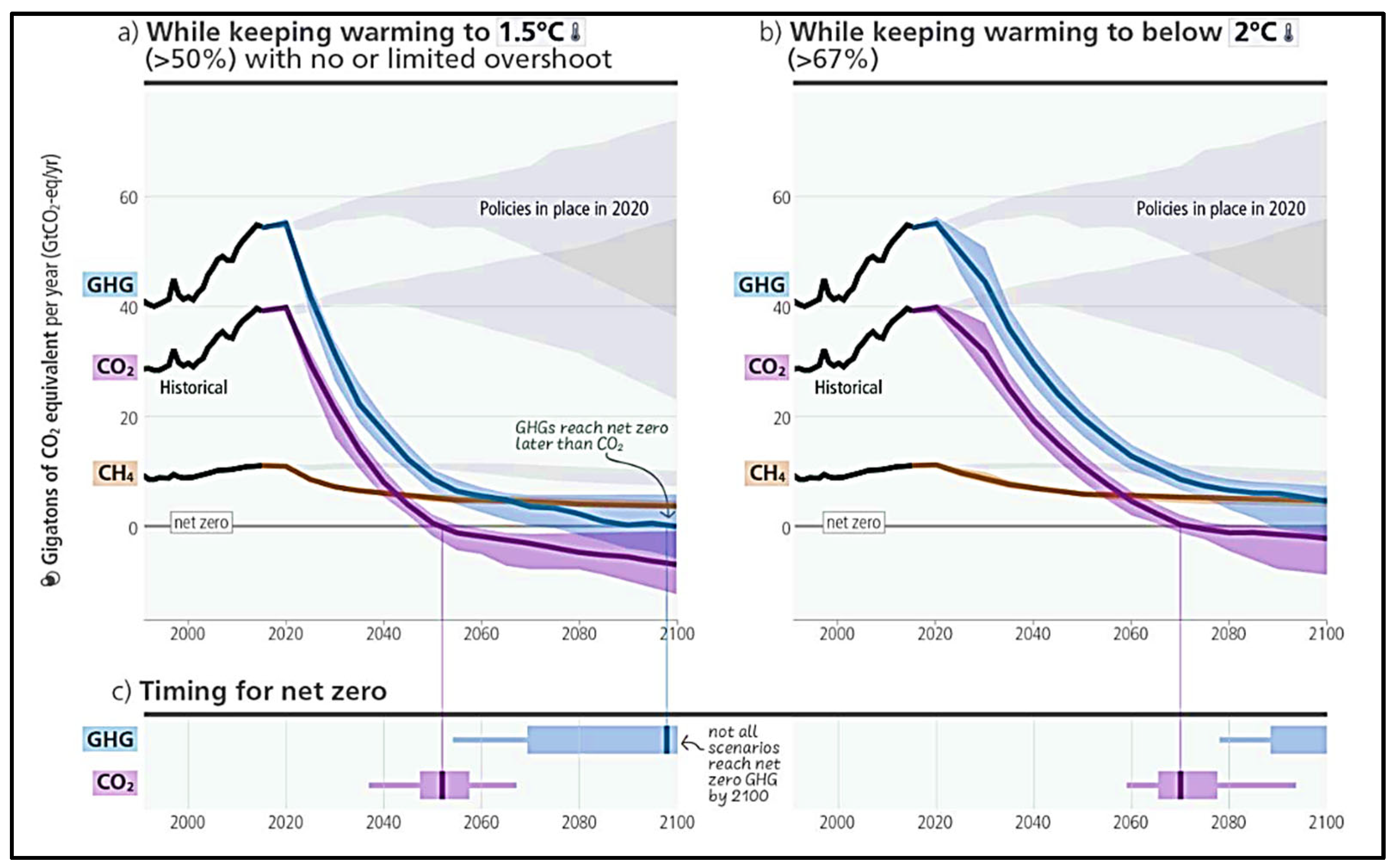
| CH4 | Methane |
| GHGs | Greenhouse gases |
| GCS | Geological carbon sequestration |
| scCO2 | Supercritical CO2 |
| CCS | Carbon capture and storage |
| THC | Coupled thermal–hydraulic–chemical |
| SEM | Scanning electron microscopy |
| XRD | X-ray diffraction |
| CT | Computerized tomography |
| HPHT | High-pressure and high-temperature |
| 11C-CO2 | Carbon 11 carbon dioxide |
| PET | Positron emission tomography |
| (CaO·SiO2·H2O) | Calcium silicate hydrate |
| Ca(OH)2 | Calcium hydroxide |
| CaCO3 | Calcium carbonate |
| K | Permeability |
| Φ | Porosity |
| NaCl | Sodium chloride |
Appendix A
| Sample | Temp (°C) | Pressure (Mpa) | Experimental Setup | Research Findings |
|---|---|---|---|---|
| Lower Tuscaloosa Formation [115] | 85 | 23.8 | Static System (in situ condition) | The exposure time to CO2 was 180 days, resulting in a 7% decrease in φ and a 13% decrease in K due to feldspar dissolution, migration, and secondary mineral precipitation, which collectively altered the pore structure. |
| Vermillion Sandstone [116] | 85 | 23.8 | Static System (in situ condition) | The exposure time to CO2 was 180 days, resulting in a 50% decrease in K due to feldspar dissolution, migration, and secondary mineral precipitation, which collectively altered the pore structure of the sandstone. |
| Knox County [116] | 85 | 23.8 | Static System (in situ condition) | The exposure time to CO2 was 180 days, resulting in increased K linked to mineral dissolution (most likely feldspar). Mineral precipitation occurred primarily on the sample’s external surface. |
| Sandstone [117] | 200 | 10 | HPHT Reactor | Demonstrate that the ankerite dissolution and clay minerals can elevate the Ca2+, Mg2+, and Fe2+ concentration, ultimately leading to silicate precipitation in CO2. Additionally, these processes can induce changes in reservoir φ and K. |
| Sandstone [36] | 40 | 2–6 | Reactor Chamber | Long-term CO2 reactions in the aquifer result in a 49% pH drop over 1.5 years, forming carbonic acid. This process leads to significant mineral dissolution, including Ca2+ and quartz, increasing pore fluid concentrations. Consequently, drying-out effects and NaCl crystallization occur within the rock pore space of the aquifer. |
| Selma Chalk [115] > 90 calcite | 85 | 23.8 | Static System (in situ condition) | Selma chalk is a promising candidate as a secondary seal with unchanged K over six months. |
| Limestone [118] | 20 | 0.3 | Chemical Analysis and Micro-CT | The 15 h experiment, at an injection rate of 100 cc/h, revealed an uneven increase in φ, connectivity, and reactive surface area due to dissolution. |
| Carbonate [117] | 200 | 10 | HPHT Reactor | This finding and other significant results contribute to our understanding of CO2–brine–rock interactions and provide valuable insights for long-term carbon storage. |
| Carbonate [42] (gypsum and dolomite) | 55 | 23.8 | Static Batch Reactor | Mineral dissolution and precipitation alter the deposit for CO2 storage, enhancing void connectivity. Both minerals dissolved, increasing K. After six months, the total φ slightly decreased from 19.5% to 19.35%. |
| Calcite and Dolomite [16] | 60 | 12 | Chemical Analysis | This paper summarizes recent work on CO2 exsolution and mineral effects in GCS reservoirs, emphasizing carbon component behavior (CO2 (sc/g), CO2 (aq), HCO3−, calcite, and dolomite). The discussion emphasizes the transport mechanisms involving coupled geochemical and two-phase flow processes, addressing their implications for long-term safety. Experimental findings revealed that mineral dissolution affects both capillary pressure and permeability, which are pivotal factors in reservoir flow modeling. |
| Basalt (Auckland volcanic) [119] | 100 | 5.5 | Reactor Chamber | In a 140-day study on basalt samples, CO2–water–rock reactions increased φ and reduced rigidity due to dissolution; secondary mineral phases formed, including chemically zoned ankerites and aluminosilicates, creating new pores. Basalts with higher initial φ and volcanic glass content exhibited a 15.3% φ increase and a threefold K increase, suggesting potential impacts in CO2 sequestration scenarios. |
| Lower Tuscaloosa Sandstone [120] | 85 | 23.8 | Static Reactor | An experimental study investigated the geochemical CO2–brine–rock interactions under geologic CO2 storage conditions in a static reaction system to probe potential changes. The permeability of the sandstone formation was observed to decrease. |
| Marine Shale (primary sealing formation) [120] | 85 | 23.8 | Static Reactor | Marine shale permeability increased after CO2 exposure, impacting primary seal integrity in CO2 storage. The change is attributed to reactive mineral composition, sample heterogeneity, and delamination, with altered shale permeability being observed to be 1000 times less than sandstone. |
| Lithic Sandstone and Calcareous Mudstone (deep coal seams) [106] | 160 | 15 | Reactor | In deep coal seam CO2 storage, a 12-day experimental study revealed that cap rock actively participates in crucial chemical reactions for geological CO2 sequestration. Alterations in lithic sandstone include significant silicate dissolution, while calcareous mudstone exhibits higher reactivity, forming dolomite, siderite, illite, and chlorite. The formation of clay minerals in the cap rock reduces φ, enhancing CO2 containment security and preventing groundwater pollution. |
| Mafic Rock (outcrops) [121] | 69.8 | 8.27 | Batch Reactor | Carbon mineralization in mafic rocks is assessed through experiments on rock characteristics, mineralogy, pore structure, and geomechanics pre- and post-CO2 exposure. The results reveal reactivity with mafic mineral dissolution, new carbonate precipitation, reduced φ (2.2% to 4.5%), and K reaching the measurement limit. Surface rock hardness and Young’s modulus notably increase, with a maximum of 903% and 91% in one sample. An indirect correlation between φ and rock hardness/Young’s modulus is observed, while Poisson’s ratio shows no change after CO2 interaction. |
| Sample | Temp (°C) | Pressure (Mpa) | Experimental Setup | Research Findings |
|---|---|---|---|---|
| Sandstone [122] | 40 | 10 | Core Flooding | The CT images of CO2 saturation reveal no significant evidence of gravity override during CO2 injection, even at the relatively low injection rate of 0.1 cc/min. |
| Sandstone [123] | 40 | 10 | Core Flooding | A 1D model was developed to simulate the core flooding test performed on the Berea core. Efforts were made to match the evolution of mean CO2 saturation profiles during injection, covering rates from 0.1 cc/min to 4.5 cc/min. |
| Sandstone [124] | 40 | 10 | Core Flooding | An experimental setup was established to investigate the scCO2 dissolution and the transfer of dissolved CO2 in mobile water within (low-K) cores. The experiments were conducted at a flow rate of 1.0 mL/min over 37 h. |
| Savonnières [49] > 97 Calcite | 50 | 11.7 | Core Flooding | At a rate of 0.4 mL/h, the continuous decrease in injectivity in the samples due to the dissolution and precipitation of calcite poses a greater risk, mainly if these processes occur near the wellbore, leading to reduced injectivity and potential shutdown of the CCS operation. |
| Carbonate [54] > 97% Calcite | 50 | 9 | Core Flooding | At a flow rate of Q = 1.667 × 10⁻⁹ m3/s and under relatively high Péclet and Damköhler numbers, we observe wormhole formation and propagation, accompanied by alterations in K and φ resulting from dissolution and precipitation. |
| Savonnières [37] > 97 Calcite | 50 | 10 | Core Flooding | At a formation water pH of 3 to 4, chemical reactions impact mechanical properties, leading to increased K and φ. In limestone, these reactions weaken the consolidated area and vice versa, with an injection rate of 0.5 mL/min. |
| Dolomite–Calcite [112] | 31 | 18 and 22 | Core Flooding | CO2 sequestration in the Asmari Formation at 1 mL/min and 2 mL/min for 2 and 4 weeks significantly alters geochemical properties, impacting the mineralogical structure. K decreases from 51.8 to 15.06 mD with a φ drop from 22.90 to 15.56. This finding suggests that formations (highly fractured) can safely store CO2, expanding storage locations globally. Long-term CO2 reactions induce dry-out effects and precipitation of NaCl in the pore space of aquifers, increasing the concentration of Na+ from 7300 to 9000 mg/L, with increments of K+ and Mg+ in the pore fluid. |
| Siltstone [125] | 35 | 8.5–9.5 | Core Flooding | The study investigates the impact of salinity levels in formation fluid on siltstone caprock K during scCO2 dominant advective flow. Siltstone caprock samples, saturated with synthetic brines resembling natural fluids, underwent scCO2 K experiments. The results reveal a significant reduction in scCO2 K at high salinity concentrations, attributed to evaporite deposition in rock pores, dependent on brine elemental concentration and caprock–brine interaction, known as the CO2 dry-out phenomenon. |
References
- US Energy Information Administration. Annual Energy Outlook 2023: Narrative. 2023. Available online: https://www.eia.gov/outlooks/aeo/pdf/AEO2023_narrative.pdf (accessed on 2 July 2024).
- Davis, S.J.; Lewis, N.S.; Shaner, M.; Aggarwal, S.; Arent, D.; Azevedo, I.L.; Benson, S.M.; Bradley, T.; Brouwer, J.; Chiang, Y.M.; et al. Net-Zero Emissions Energy Systems. Science 2018, 360, eaas9793. [Google Scholar] [CrossRef]
- Ganesh, T.; Bose, S.; Selveindran, A. Carbon Storage Focused Reservoir Management: A Practical Example to Respond to Climate Change. In Proceedings of the Future Technologies Conference; Springer Nature: Cham, Switzerland, 2023. [Google Scholar]
- IPCC. Climate Change 2023: Synthesis Report; Lee, H., Romero, J., Eds.; Contribution of Working Groups I, II and III to the Sixth Assessment Report of the Intergovernmental Panel on Climate Change; IPCC: Geneva, Switzerland, 2023; pp. 35–115. [Google Scholar] [CrossRef]
- Ali, F.; Mohamed, S.M.; Soliman, Y. Limitations and Fallacies of Carbon Capture and Storage (CCS) and Impact on Oil and Gas Production. In Proceedings of the SPE Annual Technical Conference and Exhibition, San Antonio, TX, USA, 16–18 October 2023. [Google Scholar] [CrossRef]
- Ajayi, T.; Gomes, J.S.; Bera, A. A Review of CO2 Storage in Geological Formations Emphasizing Modeling, Monitoring and Capacity Estimation Approaches. Pet Sci. 2019, 16, 1028–1063. [Google Scholar] [CrossRef]
- IPCC. 2005: IPCC Special Report on Carbon Dioxide Capture and Storage; Metz, B., Davidson, O., de Coninck, H.C., Loos, M., Meyer, L.A., Eds.; Prepared by Working Group III of the Intergovernmental Panel on Climate Change; Cambridge University Press: Cambridge, UK; New York, NY, USA, 2005; 442p. [Google Scholar]
- Zhao, X.; Liao, X.; Wang, W.; Chen, C.; Rui, Z.; Wang, H. The CO2 Storage Capacity Evaluation: Methodology and Determination of Key Factors. J. Energy Inst. 2014, 87, 297–305. [Google Scholar] [CrossRef]
- CO2 Trapping Mechanisms. Available online: https://www.bigskyco2.org/node/127 (accessed on 2 July 2024).
- Al Hameli, F.; Belhaj, H.; Al Dhuhoori, M. CO2 Sequestration Overview in Geological Formations: Trapping Mechanisms Matrix Assessment. Energies 2022, 15, 7805. [Google Scholar] [CrossRef]
- Peter, A.; Yang, D.; Eshiet, K.I.I.I.; Sheng, Y. A Review of the Studies on CO2–Brine–Rock Interaction in Geological Storage Process. Geosciences 2022, 12, 168. [Google Scholar] [CrossRef]
- Zhang, L.; Wang, Y.; Miao, X.; Gan, M.; Li, X. Geochemistry in Geologic CO2 Utilization and Storage: A Brief Review. Adv. Geo-Energy Res. 2019, 3, 304–313. [Google Scholar] [CrossRef]
- DePaolo, D.J.; Cole, D.R. Geochemistry of Geologic Carbon Sequestration: An Overview. Rev. Miner. Geochem. 2013, 77, 1–14. [Google Scholar] [CrossRef]
- Jun, Y.S.; Giammar, D.E.; Werth, C.J. Impacts of Geochemical Reactions on Geologic Carbon Sequestration. Environ. Sci. Technol. 2013, 47, 3–8. [Google Scholar] [CrossRef]
- Bickle, M. Geological carbon storage. Nat. Geosci. 2009, 2, 815–818. [Google Scholar] [CrossRef]
- Xu, R.; Li, R.; Ma, J.; He, D.; Jiang, P. Effect of Mineral Dissolution/Precipitation and CO2 Exsolution on CO2 Transport in Geological Carbon Storage. Acc. Chem. Res. 2017, 50, 2056–2066. [Google Scholar] [CrossRef]
- Gaus, I.; Audigane, P.; André, L.; Lions, J.; Jacquemet, N.; Durst, P.; Czernichowski-Lauriol, I.; Azaroual, M. Geochemical and Solute Transport Modelling for CO2 Storage, What to Expect from It? Int. J. Greenh. Gas. Control 2008, 2, 605–625. [Google Scholar] [CrossRef]
- André, L.; Audigane, P.; Azaroual, M.; Menjoz, A. Numerical Modeling of Fluid-Rock Chemical Interactions at the Supercritical CO2-Liquid Interface during CO2 Injection into a Carbonate Reservoir, the Dogger Aquifer (Paris Basin, France). Energy Convers. Manag. 2007, 48, 1782–1797. [Google Scholar] [CrossRef]
- Olivier, B.; Quisel, N.; Le Gouevec, J. Risk and Safety Evaluation for CO2 Geological Storage. Geotechnol. Sci. Rep. 2007, 9, 27–35. [Google Scholar]
- Celia, M.A.; Bachu, S. Geological Sequestration of CO2 Is Leakage Unavoidable and Acceptable. In Proceedings of the 6th International Conference on Greenhouse Gas Control Technologies, Kyoto, Japan, 1–4 October 2002; Elsevier: Amsterdam, The Netherlands, 2003; pp. 477–482. [Google Scholar]
- Scherer, G.W.; Celia, M.A.; Prévost, J.-H.; Bachu, S.; Bruant, R.; Duguid, A.; Fuller, R.; Gasda, S.E.; Radonjic, M.; Vichit-Vadakan, W. Leakage of CO2 Through Abandoned Wells. In Carbon Dioxide Capture for Storage in Deep Geologic Formations; Elsevier: Amsterdam, The Netherlands, 2005; pp. 827–848. [Google Scholar]
- Hu, Y.; Ray, J.R.; Jun, Y.S. Na+, Ca2+, and Mg2+ in Brines Affect Supercritical CO2-Brine-Biotite Interactions: Ion Exchange, Biotite Dissolution, and Illite Precipitation. Environ. Sci. Technol. 2013, 47, 191–197. [Google Scholar] [CrossRef]
- Zhao, L.; Lin, S.; Mendenhall, J.D.; Yuet, P.K.; Blankschtein, D. Molecular Dynamics Investigation of the Various Atomic Force Contributions to the Interfacial Tension at the Supercritical CO2-Water Interface. J. Phys. Chem. B 2011, 115, 6076–6087. [Google Scholar] [CrossRef]
- Hu, Y.; Ray, J.R.; Jun, Y.S. Biotite-Brine Interactions under Acidic Hydrothermal Conditions: Fibrous Illite, Goethite, and Kaolinite Formation and Biotite Surface Cracking. Environ. Sci. Technol. 2011, 45, 6175–6180. [Google Scholar] [CrossRef]
- Kim, Y.; Wan, J.; Kneafsey, T.J.; Tokunaga, T.K. Dewetting of Silica Surfaces upon Reactions with Supercritical CO2 and Brine: Pore-Scale Studies in Micromodels. Environ. Sci. Technol. 2012, 46, 4228–4235. [Google Scholar] [CrossRef]
- Molins, S.; Trebotich, D.; Steefel, C.I.; Shen, C. An Investigation of the Effect of Pore Scale Flow on Average Geochemical Reaction Rates Using Direct Numerical Simulation. Water Resour. Res. 2012, 48, W03527. [Google Scholar] [CrossRef]
- Newell, D.L.; Carey, J.W. Experimental Evaluation of Wellbore Integrity along the Cement-Rock Boundary. Environ. Sci. Technol. 2013, 47, 276–282. [Google Scholar] [CrossRef]
- Middleton, R.S.; Keating, G.N.; Stauffer, P.H.; Jordan, A.B.; Viswanathan, H.S.; Kang, Q.J.; Carey, J.W.; Mulkey, M.L.; Sullivan, E.J.; Chu, S.P.; et al. The Cross-Scale Science of CO2 Capture and Storage: From Pore Scale to Regional Scale. Energy Environ. Sci. 2012, 5, 7328–7345. [Google Scholar] [CrossRef]
- Birkholzer, J.T.; Zhou, Q. Basin-Scale Hydrogeologic Impacts of CO2 Storage: Capacity and Regulatory Implications. Int. J. Greenh. Gas Control 2009, 3, 745–756. [Google Scholar] [CrossRef]
- Shao, H.; Ray, J.R.; Jun, Y.S. Effects of Salinity and the Extent of Water on Supercritical CO2-Induced Phlogopite Dissolution and Secondary Mineral Formation. Environ. Sci. Technol. 2011, 45, 1737–1743. [Google Scholar] [CrossRef]
- Sun, Y.; Li, Q.; Yang, D.; Liu, X. Laboratory core flooding experimental systems for CO2 geosequestration: An updated review over the past decade. J. Rock Mech. Geotech. Eng. 2016, 8, 113–126. [Google Scholar] [CrossRef]
- Kampman, N.; Bickle, M.; Wigley, M.; Dubacq, B. Fluid Flow and CO2-Fluid-Mineral Interactions during CO2-Storage in Sedimentary Basins. Chem. Geol. 2014, 369, 22–50. [Google Scholar] [CrossRef]
- Gaus, I. Role and Impact of CO2-Rock Interactions during CO2 Storage in Sedimentary Rocks. Int. J. Greenh. Gas Control 2010, 4, 73–89. [Google Scholar] [CrossRef]
- Adila, A.S.; Raza, A.; Zhang, Y.; Mahmoud, M.; Arif, M. Geochemical Interactions Among Rock/CO2/Brine Systems: Implications for CO2 Geo-Storage. In Proceedings of the Gas & Oil Technology Showcase and Conference, Dubai, UAE, 13–15 March 2023. [Google Scholar]
- Gadikota, G. Carbon Mineralization Pathways for Carbon Capture, Storage and Utilization. Commun. Chem. 2021, 4, 23. [Google Scholar] [CrossRef]
- Rathnaweera, T.D.; Ranjith, P.G.; Perera, M.S.A. Experimental Investigation of Geochemical and Mineralogical Effects of CO2 Sequestration on Flow Characteristics of Reservoir Rock in Deep Saline Aquifers. Sci. Rep. 2016, 6, 19362. [Google Scholar] [CrossRef]
- Zhang, Y.; Lebedev, M.; Sarmadivaleh, M.; Barifcani, A.; Iglauer, S. SPE-182285-MS Change in Geomechanical Properties of Limestone Due to Supercritical CO2 Injection. In Proceedings of the SPE Asia Pacific Oil & Gas Conference and Exhibition, Perth, Australia, 25–27 October 2016. [Google Scholar]
- Benson, S.M.; Cole, D.R. CO2 Sequestration in Deep Sedimentary Formations. Elements 2008, 4, 325–331. [Google Scholar] [CrossRef]
- Kharaka, Y.K.; Cole, D.R.; Hovorka, S.D.; Gunter, W.D.; Knauss, K.G.; Freifeld, B.M. Gas-Water-Rock Interactions in Frio Formation Following CO2 Injection: Implications for the Storage of Greenhouse Gases in Sedimentary Basins. Geology 2006, 34, 577–580. [Google Scholar] [CrossRef]
- Kharaka, Y.K.; Cole, D.R.; Thordsen, J.J.; Kakouros, E.; Nance, H.S. Gas-Water-Rock Interactions in Sedimentary Basins: CO2 Sequestration in the Frio Formation, Texas, USA. J. Geochem. Explor. 2006, 89, 183–186. [Google Scholar] [CrossRef]
- Knauss, K.G.; Johnson, J.W.; Steefel, C.I. Evaluation of the Impact of CO2, Co-Contaminant Gas, Aqueous Fluid and Reservoir Rock Interactions on the Geologic Sequestration of CO2. Chem. Geol. 2005, 217, 339–350. [Google Scholar] [CrossRef]
- Soong, Y.; Howard, B.; Haljasmaa, I.; Crandall, D.; Dilmore, R.; Dalton, L.; Wu, Z.; Wang, P.; Gray, M.; Shi, F. CO2/Brine/Rock Interactions in the Cedar Keys-Lawson Formation. Univers. J. Carbon Res. 2023, 1, 48–62. [Google Scholar] [CrossRef]
- Azin, R.; Mehrabi, N.; Osfouri, S.; Asgari, M. Experimental Study of CO2—Saline Aquifer-Carbonate Rock Interaction during CO2 Sequestration. Procedia Earth Planet. Sci. 2015, 15, 413–420. [Google Scholar] [CrossRef]
- Zhang, Y.; Shi, L.; Ye, Z.; Chen, L.; Yuan, N.; Chen, Y.; Yang, H. Experimental Investigation of Supercritical CO2-Rock-Water Interactions in a Tight Formation with the Pore Scale during CO2-EOR and Sequestration. ACS Omega 2022, 7, 27291–27299. [Google Scholar] [CrossRef]
- Cui, G.; Yang, L.; Fang, J.; Qiu, Z.; Wang, Y.; Ren, S. Geochemical Reactions and Their Influence on Petrophysical Properties of Ultra-Low Permeability Oil Reservoirs during Water and CO2 Flooding. J. Pet. Sci. Eng. 2021, 203, 108672. [Google Scholar] [CrossRef]
- Gao, Z.; Feng, J.; Cui, J.; Xiaoqi, W.; Chuanmin, Z.; Yuxin, S. Physical simulation and quantitative calculation of increased feldspar dissolution pores in deep reservoirs. Pet. Explor. Dev. 2017, 44, 387–398. [Google Scholar] [CrossRef]
- Gledhill, D.K.; Morse, J.W. Calcite Dissolution Kinetics in Na–Ca–Mg–Cl Brines. Geochim. Cosmochim. Acta 2006, 70, 5802–5813. [Google Scholar] [CrossRef]
- Marbler, H.; Erickson, K.P.; Schmidt, M.; Lempp, C.; Pöllmann, H. Geomechanical and Geochemical Effects on Sandstones Caused by the Reaction with Supercritical CO2: An Experimental Approach to in Situ Conditions in Deep Geological Reservoirs. Environ. Earth Sci. 2013, 69, 1981–1998. [Google Scholar] [CrossRef]
- Raza, A.; Gholami, R.; Sarmadivaleh, M. Feasibility of Limestone Reservoirs as a Carbon Dioxide Storage Site: An Experimental Study. Am. Assoc. Pet. Geol. Bull. 2020, 104, 83–96. [Google Scholar] [CrossRef]
- Awolayo, A.N.; Sarma, H.K. SPE-193815-MS Numerical Modeling of Fluid-Rock Interactions During Low-Salinity-Brine-CO2 Flooding in Carbonate Reservoirs. In Proceedings of the SPE Reservoir Simulation Conference, Galveston, TX, USA, 10–11 April 2019. [Google Scholar]
- Zhang, Y.; Sarmadivaleh, M.; Lebedev, M.; Barifcani, A.; Rezaee, R.; Testamantia, N.; Iglauer, S. OTC-26470-MS Geo-Mechanical Weakening of Limestone Due to Supercritical CO2 Injection. In Proceedings of the Offshore Technology Conference Asia, Kuala Lumpur, Malaysia, 22–25 March 2016. [Google Scholar]
- Seyyedi, M.; Mahmud, H.K.; Ben Verrall, M.; Giwelli, A.; Esteban, L.; Ghasemiziarani, M.; Clennell, B. Pore Structure Changes Occur During CO2 Injection into Carbonate Reservoirs. Sci. Rep. 2020, 10, 3624. [Google Scholar] [CrossRef]
- Abdullah, A.-D.; Aljawad, M.S.; Al-Ramadan, M.; Ibrahim, A.F.; Al Majid, M.M.; Al-Yousif, Z.; Al-Yaseri, A. The impact of CO2 saturated brine salinity on wormhole generation and rock geomechanical and petrophysical properties. Geoenergy Sci. Eng. 2024, 233, 212490. [Google Scholar]
- Gharbi, O.; Bijeljic, B.; Boek, E.; Blunt, M.J. Changes in Pore Structure and Connectivity Induced by CO2 Injection in Carbonates: A Combined Pore-Scale Approach. Energy Procedia 2013, 37, 5367–5378. [Google Scholar] [CrossRef]
- Soulaine, C.; Roman, S.; Kovscek, A.; Tchelepi, H.A. Mineral Dissolution and Wormholing from a Pore-Scale Perspective. J. Fluid Mech. 2017, 827, 457–483. [Google Scholar] [CrossRef]
- Szymczak, P.; Ladd, A.J.C. Wormhole Formation in Dissolving Fractures. J. Geophys. Res. Solid Earth 2009, 114, B06203. [Google Scholar] [CrossRef]
- Golfier, F.; Zarcone, C.; Bazin, B.; Lenormand, R.; Lasseux, D.; Quintard, M. On the Ability of a Darcy-Scale Model to Capture Wormhole Formation during the Dissolution of a Porous Medium. J. Fluid Mech. 2002, 457, 213–254. [Google Scholar] [CrossRef]
- Daccord, G.; Touboul, E.; Lenormand, R.; Schlumberger, D. Carbonate Acidizing: Toward a Quantitative Model of the Wormholing Phenomenon. SPE Prod. Eng. 1989, 4, 63–68. [Google Scholar] [CrossRef]
- Bazin, B. From Matrix Acidizing to Acid Fracturing: A Laboratory Evaluation of Acid/Rock Interactions. SPE Prod. Facil. 2001, 16, 22–29. [Google Scholar] [CrossRef]
- Egermann, P.; Bekri, S.; Vizika, O. An Integrated Approach to Assess the Petrophysical Properties of Rocks Altered by Rock-Fluid Interactions (CO2 Injection). Petrophysics 2010, 51, SPWLA-2010-v51n1a2. [Google Scholar]
- Bekri, S.; Thovert, J.-F.; Adler, P.M. Dissolution and deposition in fractures. Eng. Geol. 1997, 48, 283–308. [Google Scholar] [CrossRef]
- Daccord, G.; Lenormand, R.; Lietard, O. Chemical dissolution of a porous medium by a reactive fluid—I. Model for the “wormholing” phenomenon. Chem. Eng. Sci. 1993, 48, 169–178. [Google Scholar] [CrossRef]
- Békri, S.; Thovert, J.F.; Adler, P.M. Dissolution of Porous Media. Chem. Eng. Sci. 1995, 50, 2765–2791. [Google Scholar] [CrossRef]
- Schechter, R.S.; Gidley, J.L. The Change in Pore Size Distribution from Surface Reactions in Porous Media. AIChE J. 1969, 15, 339–350. [Google Scholar] [CrossRef]
- Sarker, M.R.H.; Siddiqui, S. Advances in Micro-CT Based Evaluation of Reservoir Rocks. In Proceedings of the SPE Saudi Arabia Section Technical Symposium, Al-Khobar, Saudi Arabia, 9–11 May 2009. [Google Scholar] [CrossRef]
- Wellington, S.L.; Vinegar, H.J. X-ray Computerized Tomography. J. Pet. Technol. 1987, 39, 885–898. [Google Scholar] [CrossRef]
- Shameem, S.; Khamees, A.A. Dual-Energy CT-Scanning Applications in Rock Characterization. In Proceedings of the SPE Annual Technical Conference and Exhibition, Houston, TX, USA, 26–29 September 2004. [Google Scholar] [CrossRef]
- Siddiqui, S.; Grader, A.S.; Touati, M.; Loermans, A.M.; Funk, J.J. Techniques for Extracting Reliable Density and Porosity Data from Cuttings. In Proceedings of the SPE Annual Technical Conference and Exhibition, Dallas, TX, USA, 9–12 October 2005. [Google Scholar] [CrossRef]
- Brattekås, B.; Fernø, M.A.; Haugen, M.; Føyen, T.; Steinsbø, M.; Graue, A.; Brekke, N.; Adamsen, T.C.H.; Rygh, C.B.; Espedal, H. Of Rats and Rocks: Using Pre-Clinical PET Imaging Facilities in Core Analysis. In Proceedings of the 2021 International Symposium of the Society of Core Analysts (SCA 2021), Online, 13–16 September 2021; Volume 366. [Google Scholar]
- Brattekås, B.; Haugen, M. Explicit Tracking of CO2-Flow at the Core Scale Using Micro-Positron Emission Tomography (ΜPET). J. Nat. Gas Sci. Eng. 2020, 77, 103268. [Google Scholar] [CrossRef]
- Zahasky, C.; Benson, S.M. Using Micro-Positron Emission Tomography to Quantify Single and Multiphase Flow in Heterogeneous Reservoirs. Energy Procedia 2017, 114, 5070–5082. [Google Scholar] [CrossRef]
- Jean-Christophe, P.; Benson, S. An experimental study on the influence of sub-core scale heterogeneities on CO2 distribution in reservoir rocks. Transp. Porous Media 2010, 82, 93–109. [Google Scholar]
- AlQuraishi, A.A.; Siddiqui, S.; Algadi, O.A. Influence of Heterogeneities on CO2 Sequestration in Potential Saline Formations. In Proceedings of the Offshore Mediterranean Conference and Exhibition, Ravenna, Italy, 29–30 March 2017. [Google Scholar]
- Wang, H.; Alvarado, V.; Bagdonas, D.A.; McLaughlin, J.F.; Kaszuba, J.P.; Grana, D.; Campbell, E.; Ng, K. Effect of CO2-Brine-Rock Reactions on Pore Architecture and Permeability in Dolostone: Implications for CO2 Storage and EOR. Int. J. Greenh. Gas Control 2021, 107, 103283. [Google Scholar] [CrossRef]
- Rochelle Christopher, A.; Czernichowski-Lauriol, I.; Milodowski, A.E. The impact of chemical reactions on CO2 storage in geological formations: A brief review. Geol. Soc. Lond. Spec. Publ. 2004, 233, 87–106. [Google Scholar] [CrossRef]
- Gunter, W.D.; Perkins, E.H.; Hutcheon, I. Aquifer disposal of acid gases: Modelling of water–rock reactions for trapping of acid wastes. Appl. Geochem. 2000, 15, 1085–1095. [Google Scholar] [CrossRef]
- Gunter, W.D.; Perkins, E.H. Aquifer Disposal of CO2-Rich Greenhouse Gases: Extension of the Time Scale of Experiment for CO2-Sequestering Reactions by Geochemical Modelling. Mineral. Petrol. 1997, 59, 121–140. [Google Scholar] [CrossRef]
- Kharaka, Y.K.; Chudaev, O.V.; Thordsen, J.J.; Armannsson, H.; Breit, G.N.; Evans, W.C.; Keith, T.E.C. Water-Rock Interaction; Routledge: London, UK, 2021; ISBN 9780203734049. [Google Scholar]
- Golfier, F.; Bazin, B.; Zarcone, C.; Lernormand, R.; Lasseux, D.; Quintard, M. Acidizing Carbonate Reservoirs: Numerical Modelling of Wormhole Propagation and Comparison to Experiments. In Proceedings of the SPE European Formation Damage Conference, The Hague, The Netherlands, 21–22 May 2001. [Google Scholar] [CrossRef]
- Kaszuba, J.P.; Janecky, D.R.; Snow, M.G. Experimental Evaluation of Mixed Fluid Reactions between Supercritical Carbon Dioxide and NaCl Brine: Relevance to the Integrity of a Geologic Carbon Repository. Chem. Geol. 2005, 217, 277–293. [Google Scholar] [CrossRef]
- Watson, M.N.; Zwingmann, N.; Lemon, N.M. The Ladbroke Grove-Katnook Carbon Dioxide Natural Laboratory: A Recent CO2 Accumulation in a Lithic Sandstone Reservoir. Energy 2004, 29, 1457–1466. [Google Scholar] [CrossRef]
- May, F. Alteration of Wall Rocks by CO2-Rich Water Ascending in Fault Zones: Natural Analogues for Reactions Induced by CO2 Migrating along Faults in Siliciclastic Reservoir and Cap Rocks. Oil Gas Sci. Technol. 2005, 60, 19–32. [Google Scholar] [CrossRef]
- Fischer, M.; Botz, R.; Schmidt, M.; Rockenbauch, K.; Garbe-Schönberg, D.; Glodny, J.; Gerling, P.; Littke, R. Origins of CO2 in Permian Carbonate Reservoir Rocks (Zechstein, Ca2) of the NW-German Basin (Lower Saxony). Chem. Geol. 2006, 227, 184–213. [Google Scholar] [CrossRef]
- Worden, R.H. Dawsonite Cement in the Triassic Lam Formation, Shabwa Basin, Yemen: A Natural Analogue for a Potential Mineral Product of Subsurface CO2 Storage for Greenhouse Gas Reduction. Mar. Pet. Geol. 2006, 23, 61–77. [Google Scholar] [CrossRef]
- Julian, C.; Guo, B.; Bai, P. Continental-Scale Magmatic Carbon Dioxide Seepage Recorded by Dawsonite in the Bowen-Gunnedah-Sydney Basin System, Eastern Australia. SEPM J. Sediment. Res. 1995, 65, 522–530. [Google Scholar] [CrossRef]
- Moore, J.; Adams, M.; Allis, R.; Lutz, S.; Rauzi, S. Mineralogical and Geochemical Consequences of the Long-Term Presence of CO2 in Natural Reservoirs: An Example from the Springerville-St. Johns Field, Arizona, and New Mexico, U.S.A. Chem. Geol. 2005, 217, 365–385. [Google Scholar] [CrossRef]
- Kweon, H. Mineralogical and Petrophysical Changes in Carbon Dioxide Sequestration. Ph.D. Thesis, University of Utah, Salt Lake City, UT, USA, 2015. [Google Scholar]
- Prashanth, M. Reaction Chemistry in Carbon Dioxide Sequestration. Ph.D. Thesis, University of Utah, Salt Lake City, UT, USA, 2012. Available online: https://collections.lib.utah.edu/dl_files/f1/da/f1dab7f252bc6a0d5f8b035d7a0749a8e9f17c21.pdf (accessed on 2 July 2024).
- Berrezueta, E.; Kovacs, T.; Herrera-Franco, G.; Mora-Frank, C.; Caicedo-Potosí, J.; Carrion-Mero, P.; Carneiro, J. Laboratory Studies on CO2-Brine-Rock Interaction: An Analysis of Research Trends and Current Knowledge. Int. J. Greenh. Gas Control. 2023, 123, 103842. [Google Scholar] [CrossRef]
- Moita, P.; Berrezueta, E.; Abdoulghafour, H.; Beltrame, M.; Pedro, J.; Mirão, J.; Miguel, C.; Galacho, C.; Sitzia, F.; Barrulas, P.; et al. Mineral Carbonation of CO2 in Mafic Plutonic Rocks, II-Laboratory Experiments on Early-Phase Supercritical CO2-Brine-Rock Interactions. Appl. Sci. 2020, 10, 5083. [Google Scholar] [CrossRef]
- Schön, J.H. Electrical Properties. In Developments in Petroleum Science; Elsevier: Amsterdam, The Netherlands, 2015; Volume 65, pp. 301–367. ISBN 9780081004043. [Google Scholar]
- Rabiu, K.O.; Abidoye, L.K.; Das, D.B. Physico-Chemical and Dielectric Parameters for the Monitoring of Carbon Sequestration in Basalt and Silica Media. Environ. Technol. Innov. 2020, 20, 101052. [Google Scholar] [CrossRef]
- Sam, H. An overview of the underground disposal of carbon dioxide. Energy Convers. Manag. 1997, 38, S193–S198. [Google Scholar]
- Eric, S.; Spycher, N.; Xu, T.; Zheng, L. TOUGHREACT V4. 13-OMP and TReactMech V1. 0 Geochemical and Reactive-Transport User Guide; Berkeley National Laboratory: Berkeley, CA, USA, 2021; Available online: https://drive.google.com/file/d/1W-O6MqYRtclMkGhv4jdxHK7-l0lXItvy/view (accessed on 2 July 2024).
- GWB 2023 Professional. Available online: https://www.gwb.com/professional.php (accessed on 2 July 2024).
- GWB Reactive Transport Modeling Guide. Available online: https://www.gwb.com/pdf/GWB/GWBtransport.pdf (accessed on 2 July 2024).
- PHREEQC Version 3. Available online: https://www.usgs.gov/software/phreeqc-version-3 (accessed on 2 July 2024).
- CrunchFlow Software for Modeling Multicomponent Reactive Flow and Transport: USER’S MANUAL. Available online: https://www.netl.doe.gov/sites/default/files/netl-file/CrunchFlow-Manual.pdf (accessed on 2 July 2024).
- Xu, T.; Sonnenthal, E.; Spycher, N.; Pruess, K. TOUGHREACT—A Simulation Program for Non-Isothermal Multiphase Reactive Geochemical Transport in Variably Saturated Geologic Media: Applications to Geothermal Injectivity and CO2 Geological Sequestration. Comput. Geosci. 2006, 32, 145–165. [Google Scholar] [CrossRef]
- Raza, A.; Gholami, R.; Rabiei, M.; Rasouli, V.; Rezaee, R.; Fakhari, N. Impact of Geochemical and Geomechanical Changes on CO2 Sequestration Potential in Sandstone and Limestone Aquifers. Greenh. Gases Sci. Technol. 2019, 9, 905–923. [Google Scholar] [CrossRef]
- Audigane, P.; Gaus, I.; Czernichowski-Lauriol, I.; Pruess, K.; Xu, T. Two-Dimensional Reactive Transport Modeling of CO2 Injection in a Saline Aquifer at the Sleipner Site, North Sea Two-Dimensional Reactive Transport Modeling of CO2 Injection in a Saline Aquifer at the Sleipner Site. Am. J. Sci. 2007, 307, 974–1008. [Google Scholar] [CrossRef]
- Thibeau, S.; Nghiem, L.X.; Ohkuma, H. A Modeling Study of the Role of Selected Minerals in Enhancing CO2 Mineralization During CO2 Aquifer Storage. In Proceedings of the SPE Annual Technical Conference and Exhibition, Anaheim, CA, USA, 11–14 November 2007. [Google Scholar] [CrossRef]
- Nghiem, L.; Shrivastavar, A.; Kohse, B.; Sammon, P. Simulation of CO2 EOR and Sequestration Processes with a Geochemical EOS Compositional Simulator. In Proceedings of the Canadian International Petroleum Conference, Calgary, AL, USA, 8–10 June 2004. [Google Scholar] [CrossRef]
- Long, N.; Peter, S.; Jim, G.; Ohkuma, H. Modeling CO2 Storage in Aquifers with a Fully-Coupled Geochemical EOS Compositional Simulator. In Proceedings of the SPE/DOE Symposium on Improved Oil Recovery, Tulsa, OK, USA, 17–21 April 2004. [Google Scholar] [CrossRef]
- Gaus, I.; Azaroual, M.; Czernichowski-Lauriol, I. Reactive Transport Modelling of the Impact of CO2 Injection on the Clayey Cap Rock at Sleipner (North Sea). Chem. Geol. 2005, 217, 319–337. [Google Scholar] [CrossRef]
- Wang, K.; Xu, T.; Wang, F.; Tian, H. Experimental Study of CO2-Brine-Rock Interaction during CO2 Sequestration in Deep Coal Seams. Int. J. Coal Geol. 2016, 154–155, 265–274. [Google Scholar] [CrossRef]
- Fatah, A.; Ben, M.H.; Bennour, Z.; Gholami, R.; Hossain, M. Geochemical Modelling of CO2 Interactions with Shale: Kinetics of Mineral Dissolution and Precipitation on Geological Time Scales. Chem. Geol. 2022, 592, 120742. [Google Scholar] [CrossRef]
- Li, Z.; Lv, Y.; Liu, B.; Fu, X. Reactive Transport Modeling of CO2-Brine–Rock Interaction on Long-Term CO2 Sequestration in Shihezi Formation. Energies 2023, 16, 670. [Google Scholar] [CrossRef]
- Wang, J.; Zhao, Y.; An, Z.; Shabani, A. CO2 Storage in Carbonate Rocks: An Experimental and Geochemical Modeling Study. J. Geochem. Explor. 2022, 234, 106942. [Google Scholar] [CrossRef]
- Berrezueta, E.; Moita, P.; Pedro, J.; Abdoulghafour, H.; Mirão, J.; Beltrame, M.; Barrulas, P.; Araújo, A.; Caeiro, M.H.; Luís, L.; et al. Laboratory Experiments and Modelling of the Geochemical Interaction of a Gabbro-Anorthosite with Seawater and Supercritical CO2: A Mineral Carbonation Study. Geoenergy Sci. Eng. 2023, 228, 212010. [Google Scholar] [CrossRef]
- Ozan, T. Geochemical Modeling Study of Shale–Brine–CO2 Interaction. Master’s Thesis, Auburn University, Auburn, AL, USA, 2021. [Google Scholar]
- Famoori, F.; Azin, R.; Osfouri, S.; Arya, N. Experimental Investigation of the Geochemical and Mineralogical Interaction between CO2 and Carbonate: Evaluation of CO2 Sequestration in Dolomite-Calcite Formations. Energy Clim. Chang. 2021, 2, 100029. [Google Scholar] [CrossRef]
- Abel, A.P. CO2 Sequestration in the Permian Basin: Examination of Above-Ground Mineralization and Subsurface Solubility Trapping Capacities and Valuation of Dawsonite Kinetics in Geologic Sequestration. Master’s Thesis, New Mexico Institute of Mining and Technology, Socorro, NM, USA, 2007. [Google Scholar]
- Zhang, Y.; Yang, J.; Yu, Y.X. Dielectric Constant and Density Dependence of the Structure of Supercritical Carbon Dioxide Using a New Modified Empirical Potential Model: A Monte Carlo Simulation Study. J. Phys. Chem. B 2005, 109, 13375–13382. [Google Scholar] [CrossRef] [PubMed]
- Soong, Y.; Howard, B.H.; Dilmore, R.M.; Haljasmaa, I.; Crandall, D.M.; Zhang, L.; Zhang, W.; Lin, R.; Irdi, G.A.; Romanov, V.N.; et al. CO2 /Brine/Rock Interactions in Lower Tuscaloosa Formation. Greenh. Gases Sci. Technol. 2016, 6, 824–837. [Google Scholar] [CrossRef]
- Soong, Y.; Howard, B.H.; Hedges, S.W.; Haljasmaa, I.; Warzinski, R.P.; Irdi, G.; McLendon, T.R. CO2 Sequestration in Saline Formation. Aerosol Air Qual. Res. 2014, 14, 522–532. [Google Scholar] [CrossRef]
- Cui, G.; Zhang, L.; Tan, C.; Ren, S.; Zhuang, Y.; Enechukwu, C. Injection of Supercritical CO2 for Geothermal Exploitation from Sandstone and Carbonate Reservoirs: CO2-Water-Rock Interactions and Their Effects. J. CO2 Util. 2017, 20, 113–128. [Google Scholar] [CrossRef]
- Noiriel, C.; Luquot, L.; Madé, B.; Raimbault, L.; Gouze, P.; van der Lee, J. Changes in Reactive Surface Area during Limestone Dissolution: An Experimental and Modelling Study. Chem. Geol. 2009, 265, 160–170. [Google Scholar] [CrossRef]
- Kanakiya, S.; Adam, L.; Esteban, L.; Rowe, M.C.; Shane, P. Dissolution and Secondary Mineral Precipitation in Basalts Due to Reactions with Carbonic Acid. J. Geophys. Res. Solid Earth 2017, 122, 4312–4327. [Google Scholar] [CrossRef]
- Soong, Y.; Crandall, D.; Howard, B.H.; Haljasmaa, I.; Dalton, L.E.; Zhang, L.; Lin, R.; Dilmore, R.M.; Zhang, W.; Shi, F.; et al. Permeability and Mineral Composition Evolution of Primary Seal and Reservoir Rocks in Geologic Carbon Storage Conditions. Environ. Eng. Sci. 2018, 35, 391–400. [Google Scholar] [CrossRef]
- Raza, A.; Mahmoud, M.; Murtaza, M.; Arif, M.; Hassan, A.; Glatz, G.; Alafnan, S.; Kamal, M.S.; Al-Karnos, A. Experimental Investigation of Mafic Rocks for Carbon Mineralization Prospect. Energy Fuels 2023, 37, 5976–5985. [Google Scholar] [CrossRef]
- Shi, J.Q.; Xue, Z.; Durucan, S. Supercritical CO2 Core Flooding and Imbibition in Tako Sandstone-Influence of Sub-Core Scale Heterogeneity. Int. J. Greenh. Gas Control 2011, 5, 75–87. [Google Scholar] [CrossRef]
- Shi, J.Q.; Xue, Z.; Durucan, S. Supercritical CO2 Core Flooding and Imbibition in Berea Sandstone—CT Imaging and Numerical Simulation. Energy Procedia 2011, 4, 5001–5008. [Google Scholar] [CrossRef]
- Chang, C.; Zhou, Q.; Guo, J.; Yu, Q. Supercritical CO2 Dissolution and Mass Transfer in Low-Permeability Sandstone: Effect of Concentration Difference in Water-Flood Experiments. Int. J. Greenh. Gas Control 2014, 28, 328–342. [Google Scholar] [CrossRef]
- Jayasekara, D.W.; Ranjith, P.G.; Wanniarachchi, W.A.M.; Rathnaweera, T.D.; Chaudhuri, A. Effect of Salinity on Supercritical CO2 Permeability of Caprock in Deep Saline Aquifers: An Experimental Study. Energy 2020, 191, 116486. [Google Scholar] [CrossRef]


Disclaimer/Publisher’s Note: The statements, opinions and data contained in all publications are solely those of the individual author(s) and contributor(s) and not of MDPI and/or the editor(s). MDPI and/or the editor(s) disclaim responsibility for any injury to people or property resulting from any ideas, methods, instructions or products referred to in the content. |
© 2024 by the authors. Licensee MDPI, Basel, Switzerland. This article is an open access article distributed under the terms and conditions of the Creative Commons Attribution (CC BY) license (https://creativecommons.org/licenses/by/4.0/).
Share and Cite
Khan, M.N.; Siddiqui, S.; Thakur, G.C. Recent Advances in Geochemical and Mineralogical Studies on CO2–Brine–Rock Interaction for CO2 Sequestration: Laboratory and Simulation Studies. Energies 2024, 17, 3346. https://doi.org/10.3390/en17133346
Khan MN, Siddiqui S, Thakur GC. Recent Advances in Geochemical and Mineralogical Studies on CO2–Brine–Rock Interaction for CO2 Sequestration: Laboratory and Simulation Studies. Energies. 2024; 17(13):3346. https://doi.org/10.3390/en17133346
Chicago/Turabian StyleKhan, Muhammad Noman, Shameem Siddiqui, and Ganesh C. Thakur. 2024. "Recent Advances in Geochemical and Mineralogical Studies on CO2–Brine–Rock Interaction for CO2 Sequestration: Laboratory and Simulation Studies" Energies 17, no. 13: 3346. https://doi.org/10.3390/en17133346