Review

Recent Advances in Geochemical and Mineralogical Studies on CO2–Brine–Rock Interaction for CO2 Sequestration: Laboratory and Simulation Studies

by
Muhammad Noman Khan
,
Shameem Siddiqui
and
Ganesh C. Thakur
*
Department of Petroleum Engineering, Cullen College of Engineering, University of Houston, Houston, TX 77204, USA
*
Author to whom correspondence should be addressed.
Energies 2024, 17(13), 3346; https://doi.org/10.3390/en17133346
Submission received: 11 June 2024 / Revised: 27 June 2024 / Accepted: 3 July 2024 / Published: 8 July 2024
(This article belongs to the Special Issue Oil Recovery and Simulation in Reservoir Engineering)

Abstract

:
The urgent need to find mitigating pathways for limiting world CO2 emissions to net zero by 2050 has led to intense research on CO2 sequestration in deep saline reservoirs. This paper reviews key advancements in lab- and simulation-scale research on petrophysical, geochemical, and mineralogical changes during CO2–brine–rock interactions performed in the last 25 years. It delves into CO2 MPD (mineralization, precipitation, and dissolution) and explores alterations in petrophysical properties during core flooding and in static batch reactors. These properties include changes in wettability, CO2 and brine interfacial tension, diffusion, dispersion, CO2 storage capacity, and CO2 leakage in caprock and sedimentary rocks under reservoir conditions. The injection of supercritical CO2 into deep saline aquifers can lead to unforeseen geochemical and mineralogical changes, possibly jeopardizing the CCS (carbon capture and storage) process. There is a general lack of understanding of the reservoir’s interaction with the CO2 phase at the pore/grain scale. This research addresses the gap in predicting the long-term changes of the CO2–brine–rock interaction using various geochemical reactive transport simulators. Péclet and Damköhler numbers can contribute to a better understanding of geochemical interactions and reactive transport processes. Additionally, the dielectric constant requires further investigation, particularly for pre- and post-CO2–brine–rock interactions. For comprehensive modeling of CO2 storage over various timescales, the geochemical modeling software called the Geochemist’s Workbench was found to outperform others. Wettability alteration is another crucial aspect affecting CO2–brine–rock interactions under varying temperature, pressure, and salinity conditions, which is essential for ensuring long-term CO2 storage security and monitoring. Moreover, dual-energy CT scanning can provide deeper insights into geochemical interactions and their complexities.

1. Introduction

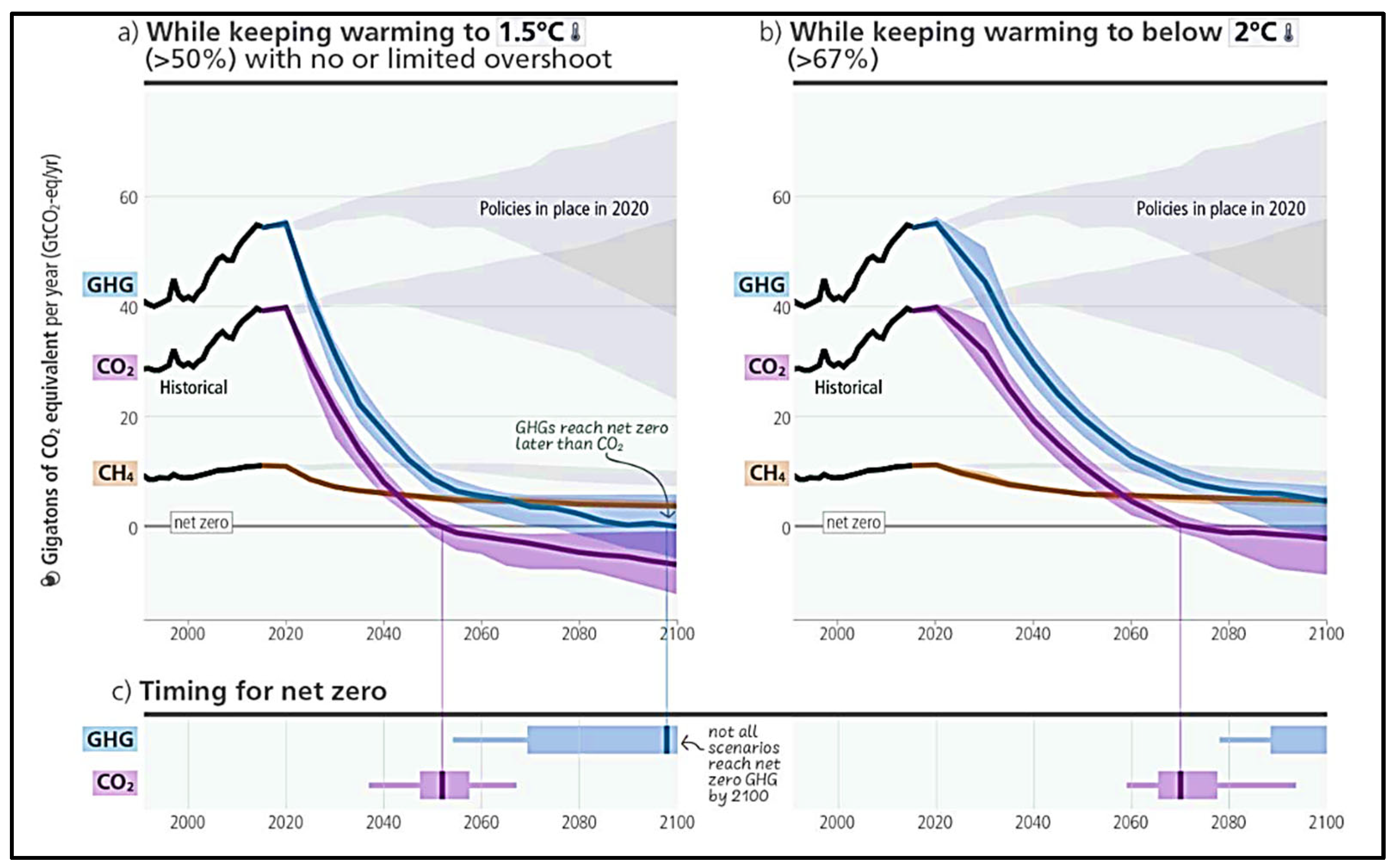
According to the Annual Energy Outlook (EIA, 2023), the United States CO2 emissions created by energy-related emissions such as electricity generation (coal, natural gas, oil), transportation (vehicles, aviation), industrial processes, and residential and commercial processes are 25% to 38% below 2005 levels, depending on economic expansion and zero-carbon technology generation costs; see Figure 1 [1]. The energy transition’s success hinges on the widespread availability of low-cost, emissions-free electricity and the substitution of most fuel-powered devices, materials, and manufacturing processes with electric alternatives. This also involves utilizing carbon capture and storage (CCS) for structural materials and creating carbon-neutral fuels for sectors that are challenging to electrify [2]. CO2 sequestration in deep saline reservoirs is not just a topic of current research but a pressing issue that demands immediate attention. With most large oil and gas companies and government policymakers being focused on reducing CO2 emissions from the environment, the urgency of this research cannot be overstated. In a recent paper, Thakur et al. [3] focused on carbon storage and reservoir management as a practical example of climate change response [3]. IPCC 2023 stated that different mitigation pathways for CO2 emissions will reach net zero by 2050 for 1.5 °C and for 2.0 °C by 2070; see Figure 2 [4]. In their paper, Farouq Ali and Soliman [5] highlighted that carbon capture and storage (CCS) has mitigated less than 0.1% of global CO2 emissions over the past two decades. This finding underscores the urgent need for enhanced efforts, given the persistent reliance on fossil fuels. Current CCS initiatives have not achieved the desired impact, emphasizing the necessity for substantial technological advancements. Developing and implementing innovative approaches that have yet to be explored by the petroleum industry and academic engineering programs is imperative to attain net-zero emissions [5]. The research presented in this paper is comprehensive, covering key aspects of the geochemical and mineralogical issues for CO2–brine–rock interactions for CO2 storage. It provides a detailed review of the experimental and simulation studies, delving into the trapping mechanism of CO2. It is divided into two parts: (1) physical trapping (less than 100 years) includes stratigraphic hydro trapping, capillary trapping, and sorption trapping; and (2) geochemical trapping includes solubility trapping (convective and diffusion processes), while mineral trapping states the chemical reactions with minerals [6,7,8,9,10,11] (see Figure 3).
Based on current trends and previous studies, extensive research has been conducted on the geochemical interactions between CO2, brine, and rock, encompassing experimental and simulation studies. Geochemistry is the main factor in carbon storage. CO2 dissolution occurs due to the chemical reaction between CO2, rock, and carbonate and bicarbonate ions present in formations, and a pH drop [12,13]. GCS depends on carbon capture. This initial process determines the impurities in injected scCO2 and injected volumes, rates, and pressures [14]. Experimental and practical data are used to understand storage processes and assess associated risks. However, knowledge gaps still exist in the field [15,16].
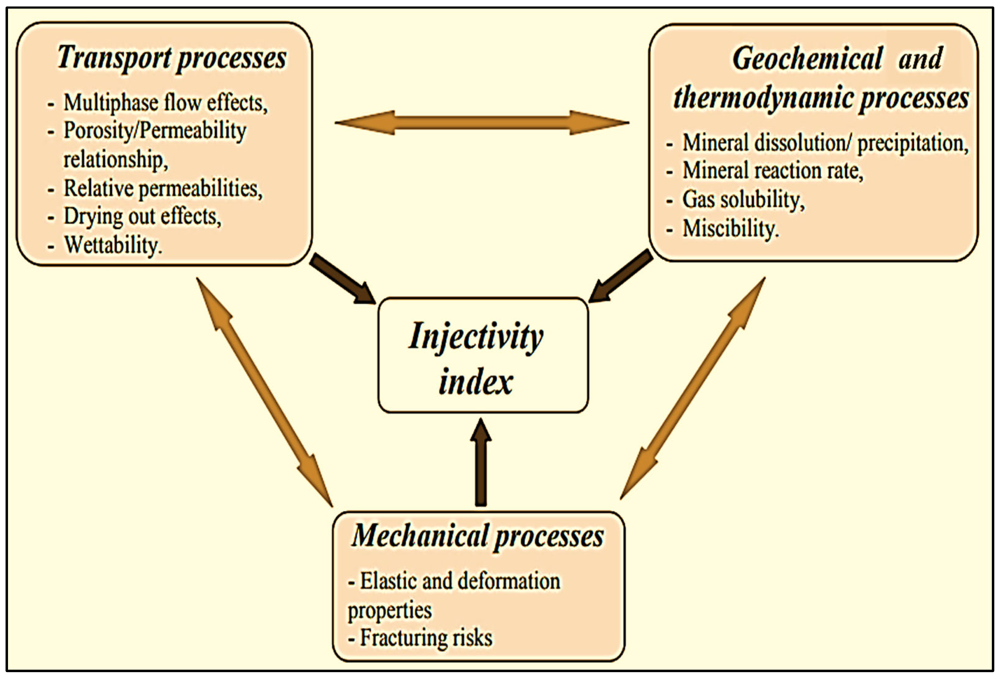
As detailed in Figure 4, the injectivity index of CO2 injection affects the geochemical, thermodynamic, transport, and mechanical processes [17]. Porosity variations resulting from geochemical interactions and how this affects the CO2 injectivity; these are validated by coupled modeling applications [18]. In the geochemical interactions between CO2, brine, and rock, substantial changes occur depending on the type of rock. In the near-wellbore region, chemical reactions occur between the gas mixture, brine, and cement or steel. This process, known as carbonation, involves the conversion of constitutive cement minerals such as (CaO·SiO2·H2O) and Ca(OH)2 by CO2. Specifically, CO2 reacts with the Ca(OH)2 in the cement to form (CaCO3), which can significantly impact the mineralogy, porosity, transport, and mechanical properties of the cement. For long-term CO2 storage security, crucial for periods exceeding 1000 years, these changes could lead to increased permeability, diffusivity, fissures, and annular spaces between the casing and cement, thereby elevating the risk of CO2 leakage to the surface [17,19,20,21].
Figure 5 illustrates a comprehensive overview of geological carbon storage across laboratory and spatial scales of multiphase reactive transport, focusing on A. nano-scale (mineral–fluid experiments and theoretical geochemistry involving dissolution and precipitation); B. pore-scale (bench-scale experiments and pore-scale modeling); and C. reservoir scale (core flooding and reactive transport modeling) [14,22,23,24,25,26,27,28,29].

2. Mechanisms for CO2–Brine–Rock Interactions

The mechanism of CO2–brine–rock interactions involves very complex chemical reactions. There is a significant lack of understanding regarding reservoir interactions with CO2 at the pore/grain scale [11]. This knowledge gap emphasizes the potential risks of unforeseen geochemical and mineralogical changes during scCO2 injection. In GCS conditions, there are four most impactful chemical reactions: (1) the dissolution of scCO2 in brine; (2) the creation of secondary minerals because of reactions driven by CO2-enriched brine; (3) water, rock, and scCO2 interactions called wet scCO2-induced interactions; and (4) near-wellbore reactions, which depend on several factors such as pressure, temperature, salinity, and rock mineralogy. These reactions can form in situ nanoparticles, affecting the pore throat and causing wettability alterations (see Figure 6) [14,26,30].
CO2, brine, and rock interaction mechanisms induce various geochemical reactions that significantly influence MPD. These interactions can profoundly affect the subsurface environment in carbon sequestration, which is crucial for geochemical and mineralogical interactions among CO2, brine, and rock.
Fluid–mineral reactions can have significant consequences:
  • The rapid dissolution of carbonates can lead to the degradation of caprocks, wellbores, and fault seals, potentially allowing CO2 to migrate into overlying formations and cause equipment leakage [31].
  • Carbonate precipitation in caprocks can lower the permeability, stabilizing storage.
  • Mineral dissolution or precipitation in reservoirs may change permeability, affecting the flow of CO2 and CO2-saturated brine.
  • CO2 sequestration into carbonate rocks and minerals contributes to long-term storage security [32,33].
Geochemical reactions between CO2 and reservoir or caprock in deep subsurface environments are primarily driven by a decrease in pH and the formation of bicarbonate and carbonate ions due to CO2 dissolution [12]. Despite this, the wettability interactions among CO2, calcite, and brine remain not fully understood from a geochemical standpoint [34].
In Section 2.2 of this paper, we can correlate the above four points using CT scanning technology, which offers valuable insights. There is a direct connection between in situ visualization using CT scanning and the MPD to analyze the dissolution of scCO2 in brine to create acidified brine, the CO2 saturation profile in the core sample, mineral precipitation, calcite dissolution, and various time-dependent geochemical reactions during CO2 sequestration. These chemical reaction processes are explained in more detail in Figure 6. Dual-energy and micro-CT scans can provide important visual insights into geochemical interactions. With ISSM (in situ saturation monitoring), industrial/micro-CT scanners can observe and quantify the complex structural effects of these processes and potentially mitigate the risks and challenges they pose. Mineralization, precipitation, and dissolution can be seen using ISSM techniques, offering a unique perspective. A CT scanner has the ability to monitor small changes in density and effective atomic number, Zeff, providing a window into the dynamic nature of these processes. The higher the density or Zeff of a rock, the higher the grayscale number (or Hounsfield number). Under in situ conditions, a rock sample is exposed to CO2 and brine inside an X-ray transparent core holder. It is then scanned periodically to monitor any grayscale number changes taking place in CT slices compared with the initial scans before exposure, which can be related to saturation changes.

2.1. MPD (Mineralization, Precipitation, and Dissolution)

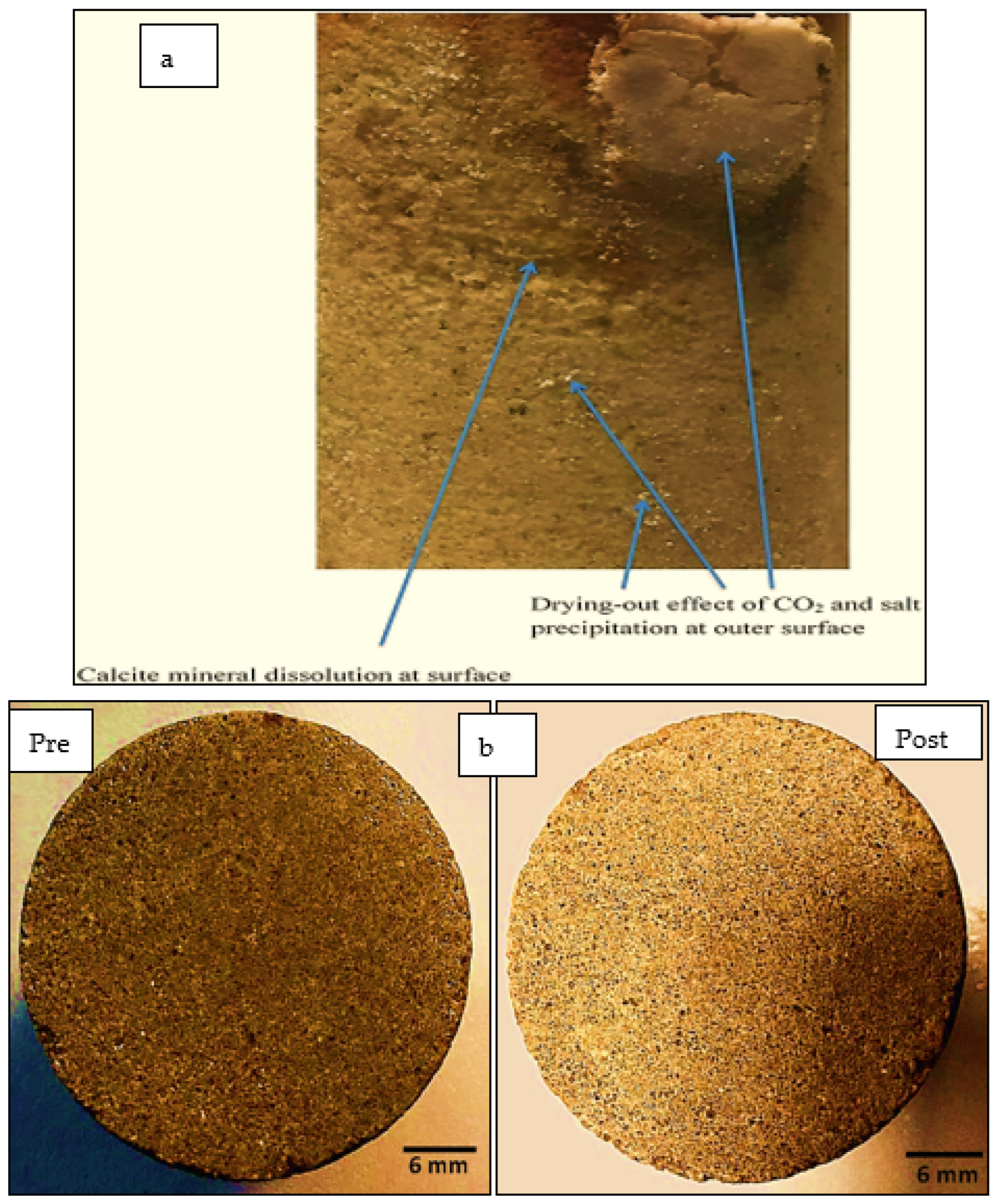
Carbon mineralization (conversion to solid inorganic carbonates) in the subsurface is a very impactful factor for carbon management efforts. Calcium or magnesium carbonates are formed from stoichiometric and chemo-morphological reactions [35]. Mineral dissolution and precipitation can change the permeability of the reservoir [12]. In their meticulous investigation, Rathnaweera et al. [36] looked at the impact of prolonged CO2 injection. Their research revealed a CO2 drying-out effect, accompanied by the precipitation of NaCl crystals in sandstone (see Figure 7a). These processes significantly impact rocks’ mineralogical properties and permeability within saline aquifers. The dissolution of minerals such as calcite, siderite, barite, and quartz was identified as the primary cause of these changes, a conclusion that was reached through rigorous scientific methods. Figure 7b shows the before-and-after images of a carbonate core subjected to scCO2 injection; it provides the dissolution of calcite minerals after reaction with a rock to form carbonic acid. The fine particles inside the limestone core sample are dissolved by the carbonic acid [37].
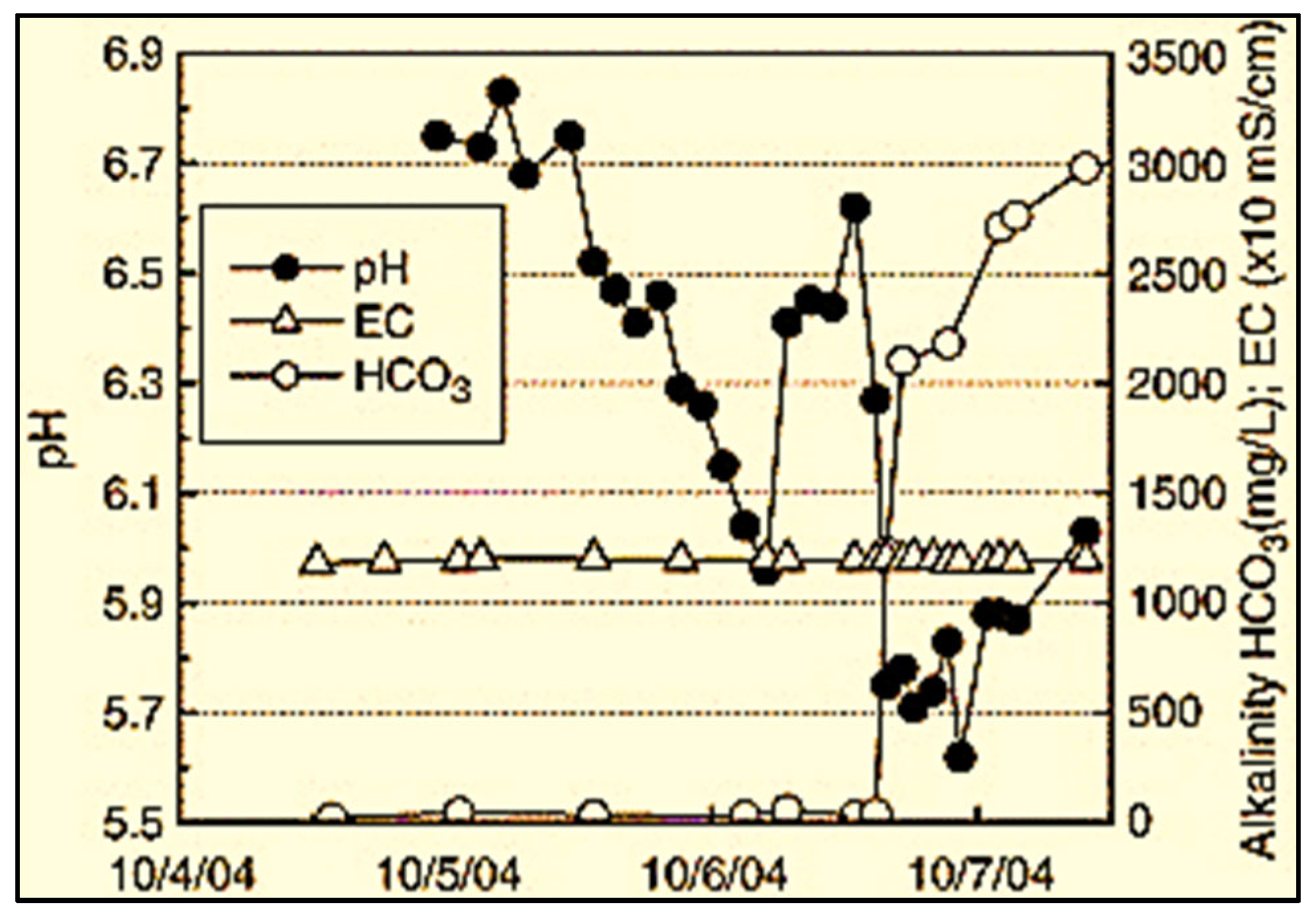
When CO2 is impure and contains other plant gases, such as oxides of sulfur and nitrogen, it can undergo geochemical interactions and reactions with the formation of rock and brine, altering the mineralogical and equilibrium thermodynamic conditions. CO2 dissolves in brine, reducing the pH and leading to primary phase dissolution and secondary mineral precipitation. These reactions can change the permeability and porosity of the rock [38]. Figure 8 presents a practical example of CO2 sequestration in sedimentary basins in the Frio Formation in Texas, USA, illustrating the decline in pH and the concurrent alkalinity increases following the breakthrough of CO2 [39,40]. The dissolution of iron oxyhydroxides can mobilize toxic metals, potentially contaminating groundwater. Additionally, the presence of sulfur oxides can lead to the formation of H2S and significantly lower the pH [41].
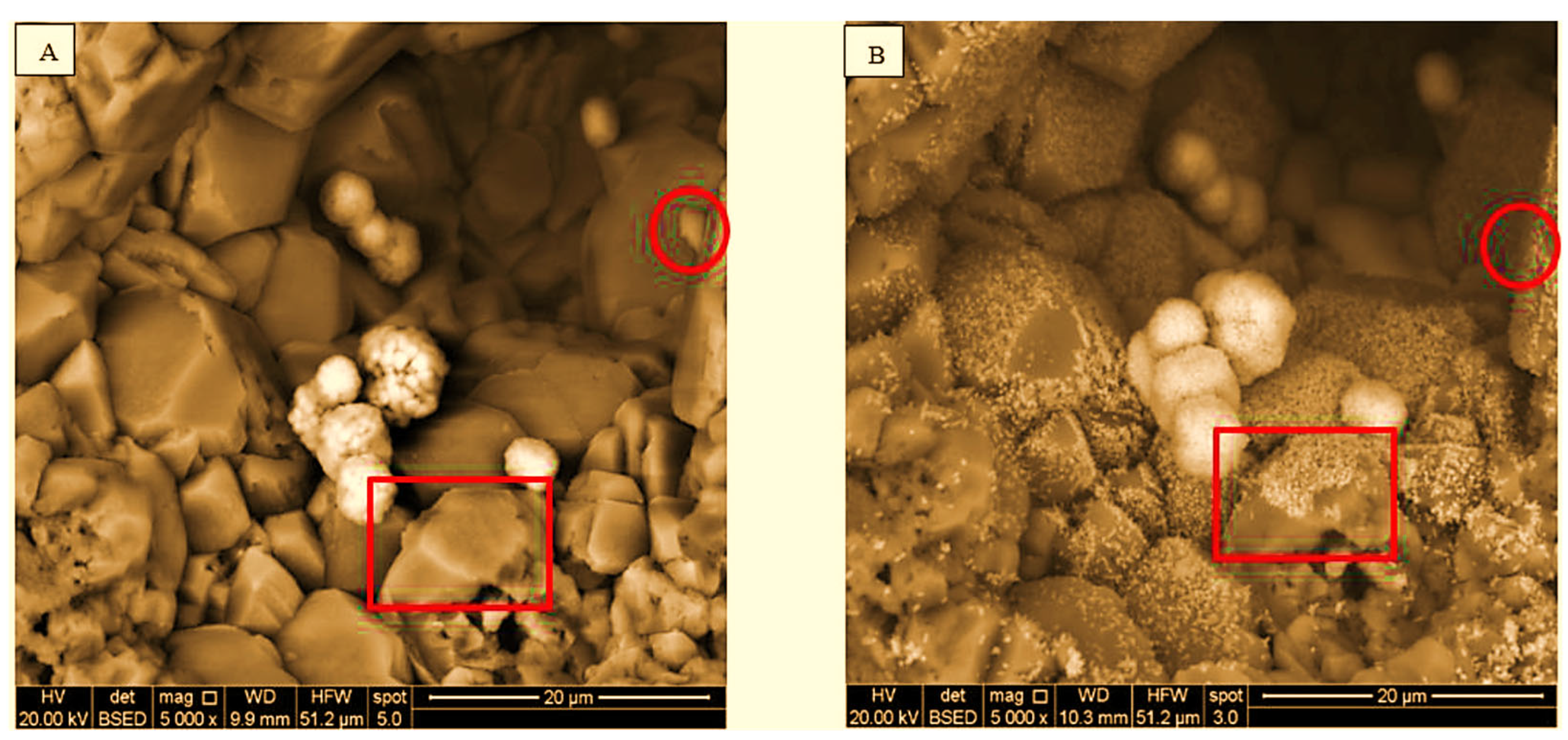
X-ray diffraction (XRD) and scanning electron microscopy (SEM) are analytical techniques that provide detailed insights into grain structures, pore characteristics, and the changes induced by the continuous injection of supercritical CO2 (scCO2) in carbon sequestration processes. Figure 9A,B visually illustrate the mineral dissolution and precipitation resulting from CO2–brine–rock interactions [42]. These interactions led to brine acidification, evidenced by increased calcium and magnesium ions. This, in turn, caused the dissolution of carbonate minerals and increased the porosity and permeability of the formation rock [43]. Figure 10 highlights the dissolved areas, such as feldspar dissolution, pore formation, and kaolinization, and their effects on the connectivity of tight reservoir rocks [44,45]. Figure 11 illustrates the pore expansion observed in feldspar during the CO2–rock test. Conversely, in the case of CO2–water–rock interactions, the most significant pore expansion was observed in kaolinite, along with mass loss and alterations in permeability and porosity in tight cores following CO2–water–rock experiments [44,46].
Rathnaweera et al. [36,47,48] investigated the interactions between CO2, rock, and brine in a study. SEM observations revealed distinctive features in the reacted samples, including calcite dissolution textures, etching caverns, pits, and the corrosion of quartz minerals, resulting in a relatively rough surface on sandstone samples. Calcite dissolution within carbonate-cemented reservoirs led to significant alterations in pore structures.
Figure 12 illustrates various effects of CO2 injection on cores from a limestone reservoir [49]. Point A shows dissolution occurring at the grain level; points B and D show grain breakage due to CO2 reaction with the core; point C shows mass loss at the grain level; and point E shows cement dissolution [49]. These findings signify a loss of integrity and underscore the potential for mechanical failure in limestone reservoirs, which is a crucial aspect of the CCS project.
An additional and sometimes overlooked geochemical interaction is surface complexation and associated redox equilibrium [50]. Surface reactions, particularly for low-salinity brines, can measurably impact the CO2 amounts being actively transported.

2.2. Advancements in Visualization through CT Scanners and In Situ Techniques

Recent advancements in visualization techniques, such as CT scanning, are revolutionizing in situ monitoring and analysis by enhancing our understanding of geochemical interactions and their role in carbon storage.
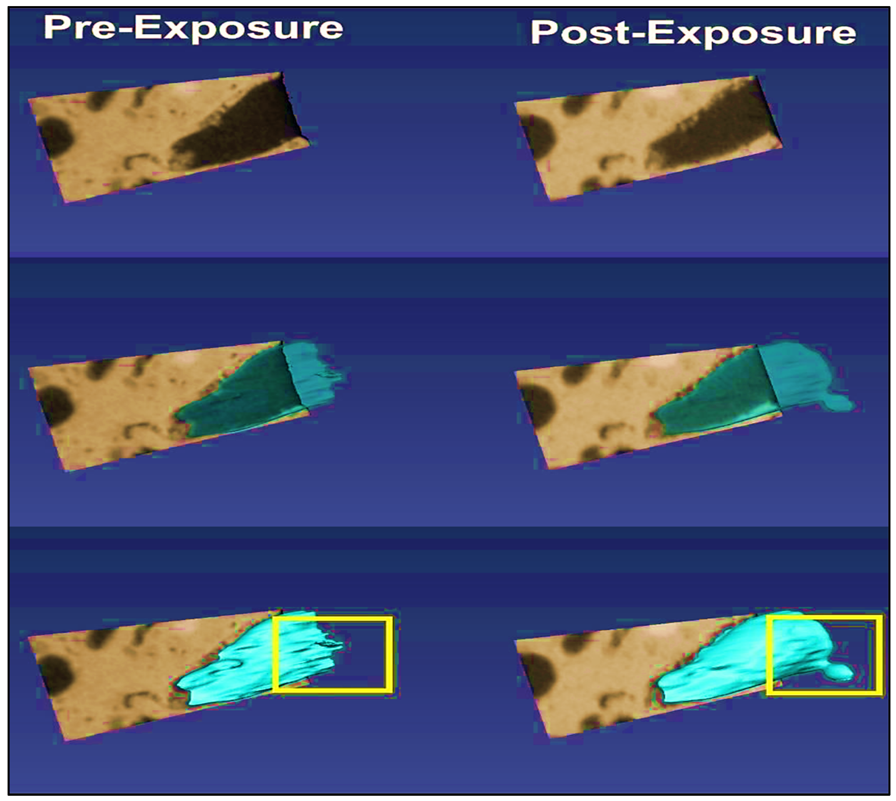
Soong et al. [42] illustrated this in their study using CT scan images of Cedar Keys/Lawson rock (carbonate formation) after one month of exposure to scCO2 and brine. The study found that porosity decreased from 19.5% to 19.35% following the CO2 reaction, indicating potential impacts on the rock’s stability. Dissolution was observed primarily in the outer region of the core, suggesting structural alterations. Additionally, the pore increased in volume by 21%, with the pore size expanding (equivalent diameter) from 1223 µm to 1304 µm, as shown in Figure 13. The permeability value decreased from 4.57 to 4.50 mD. Figure 14, which is the continuation of Figure 13, shows where the dissolution occurred and created another pore connected to the adjacent void space to create a channel.
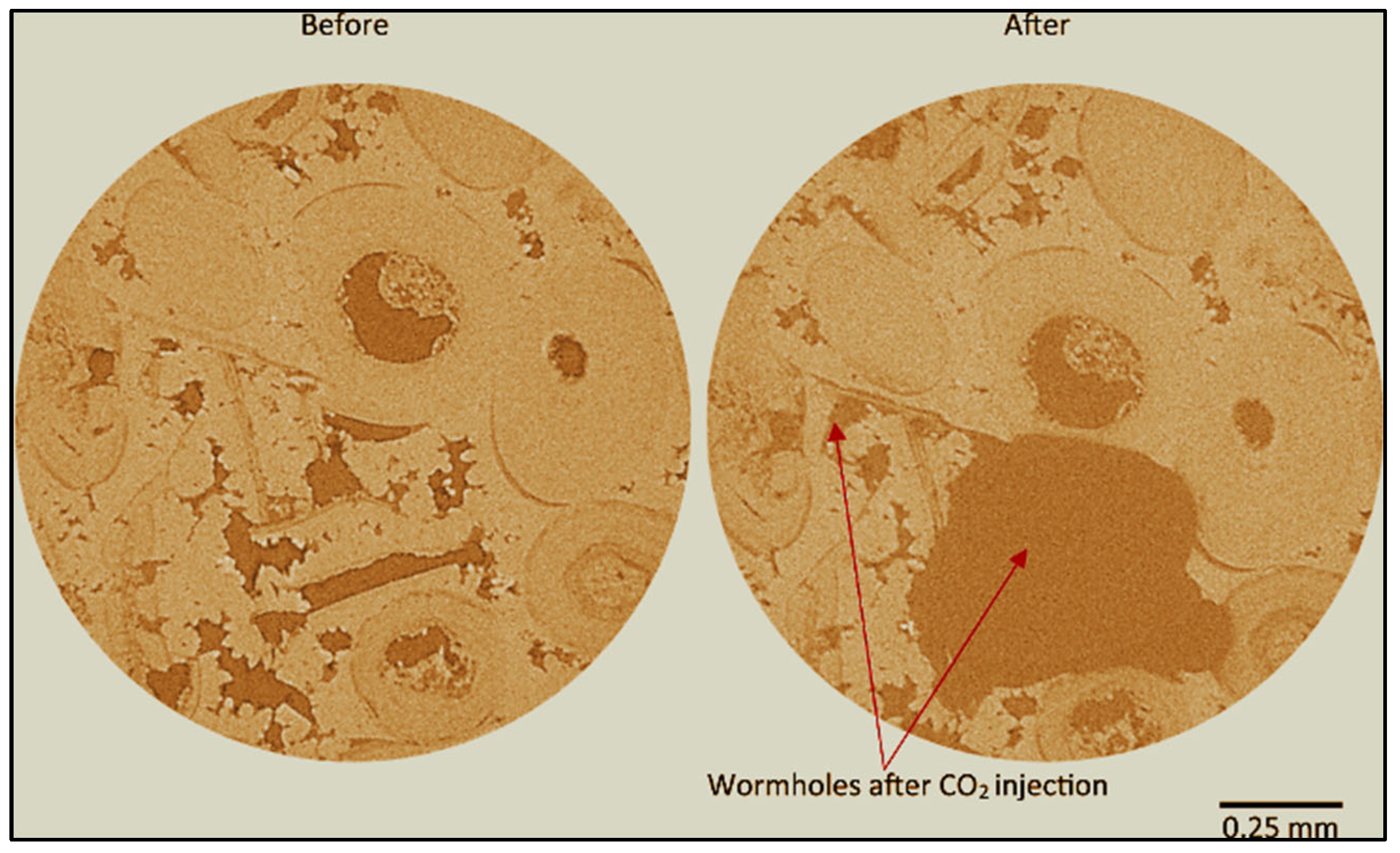
The research on wormhole creation in carbonate reservoirs for CO2–brine–rock interactions presents novel insights [51], as evidenced by the CT scan images in Figure 15 [49] and Figure 16 [52], respectively. These figures offer a unique and enlightening visual representation of wormhole formation and breakage, a phenomenon that has also been observed using a CT scan. The maximum depth of wormhole formation reached 6.3 cm. The 175% increase in absolute permeability of the sample can be attributed to dissolution and the formation of wormhole channels [52]. Another researcher documented the implication of CO2-saturated brine salinity on wormhole generation and concluded that the low-salinity brine could induce thicker wormholes in the limestone samples [53]. Importantly, Gharbi et al. [54] discovered that creating high-conductive channels, such as wormhole formations and propagation in carbonate rocks, is associated with very high Péclet and Damköhler numbers. A Péclet number is defined as the ratio of the advection rate of a chemical species by the flow to the rate of diffusion of this quantity in the fluid mixture. A Damköhler number is defined as the ratio of the reaction rate and the diffusive mass transfer rate at the fluid/solid interface [55].
Based on the literature, our study analyzed the dissolution patterns influenced by Péclet (Pé) and Damköhler (Da1) numbers, as shown in Figure 17.
  • Figure 17a: Different dissolution patterns based on varying Péclet and Damköhler numbers.
  • Figure 17b: The dissolution front remains highly stable for small Péclet numbers (Pé ≤ 10−2) and Da1 > 1.
  • Figure 17c: When Da1 > 1 and injection rates are higher but within a diffusion-dominated transport regime (1 ≥ Pé > 10−2), the dissolution front becomes non-uniform along the vertical cross-section, forming a conical pattern due to the faster regions dragging the dissolution.
  • Figure 17d: A single dominant wormhole forms for conditions where Da1 > 1 and 10 ≥ Pé > 1. In this case, advection dominates the void space due to the acid transport mechanism.
  • Figure 17e,f illustrate ramified wormhole formation for Da1 > 1 and Pé > 10, showing complex dissolution patterns. Uniform dissolution occurs for small Damköhler numbers (Da1 ≤ 1) irrespective of the Péclet number [55,56,57].
Various researchers discuss the Péclet and Damköhler numbers in acidizing and stimulation for wormhole creation. For example, the modeling of the wormhole creation has been processed to optimize the acidizing stimulation of production wells [58,59]. The dissolution regime is influenced by these two-dimensional numbers, as depicted in Figure 18 [60,61,62,63,64]. It is worth knowing that when we inject the scCO2 for geochemical interactions such as MPD processes, very little research on reactive transport phenomena based on wormhole formation and propagation based on these interactions relates to the Péclet and Damköhler numbers. As Gharbi et al. [54] stated in their paper, it is worthwhile to investigate the dissolution regimes at lower Damköhler numbers and predict the reactive transport properties and wormhole propagation.
Siddiqui et al. [65] reviewed significant research conducted using both medical and micro-CT scanners for core characterization and flow visualization. Several researchers employed CT scanners with dual-energy CT scanning for the characterization of rocks [66,67]. Dual-energy CT scanning utilizes two X-ray energies—one low and one high energy—at the exact location. This technique determines bulk density and effective atomic number, which makes it possible to accurately characterize some rock properties. Some previous studies have also compared various techniques for extracting density and porosity from cuttings. Siddiqui et al. [68] highlighted using micro-CT and medical CT scanners to achieve these measurements, demonstrating their effectiveness for capturing core heterogeneities and for use in detailed rock characterization.
Limited research has been conducted using industrial CT scanners. By employing industrial CT scanners with dual-energy techniques and by analyzing cuttings or chips using micro-CT scanners, one can potentially examine MPD interactions between CO2, brine, and rock for short- and long-term CO2 storage. This methodology enables the observation of chemical reactions in the context of reactive transport phenomena and helps identify the critical factors influencing these reactions.
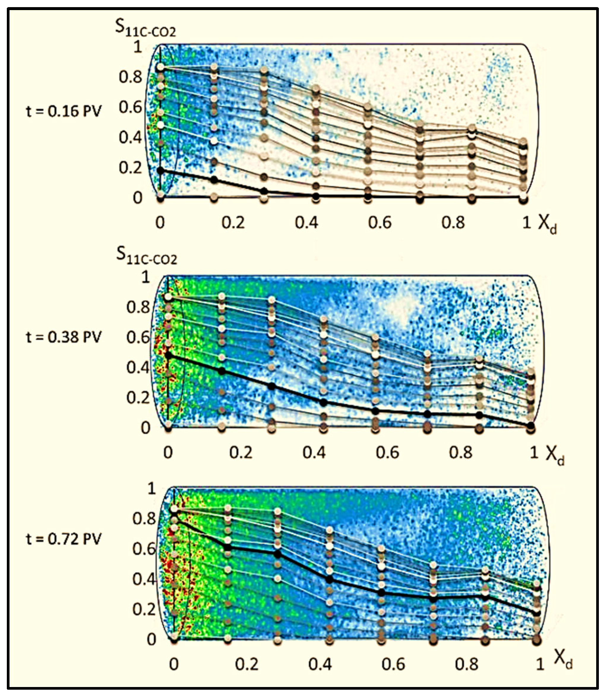
New to the area of visualization in cores is the use of positron emission tomography (PET). In this system (a more enhanced version of a CT scanner), both transmitted X-rays (CT scans) and emitted particles with associated X-rays can be observed. An example of positron emission tomography is shown in Figure 19 [69]. For CO2 injection, the specificity of selected positron emitters in the brine, CO2, or oil can be used to produce images when density variations are too small to produce a sufficient CT number contrast [70,71].
In situ techniques are new ways to observe geochemical changes associated with mineral precipitation and dissolution (MPD) in carbon sequestration lab studies. Perrin et al. [72] utilized in situ techniques to visualize the two-phase (CO2/brine) experiments using X-ray CT scanning. The study’s outcomes (samples from Victoria, southwest Australia) showed that the sweep efficiency was controlled by sub-core-scale heterogeneities while using CT scanning to visualize the in situ CO2 saturation profile. Another study [73] examined the relationship between in situ saturation profiles obtained using a CT scanner and the porosity and heterogeneity distributions, which are critical factors influencing the CO2 storage capacity within the core. In situ data on CO2 injection revealed anomalies in local saturation that are attributed to capillary effects at the core–sample interface [73]. Nuclear magnetic resonance (NMR) is a valuable technique for assessing changes in pore size measurements and can be utilized for in situ analyses. In their study, Wang et al. [74] investigated the application of time domain nuclear magnetic resonance (TD-NMR) by examining transverse relaxation time (T2) and diffusion coefficient (D) distributions to detect pore size alterations in rock samples undergoing CO2 sequestration. These changes are associated with geochemical processes such as mineral precipitation and dissolution (MPD). NMR can verify pore size modifications by revealing shifts in the peak values corresponding to different pore types in T2 and D distributions before and after CO2 sequestration. The findings from NMR are corroborated by results from other in situ measurement techniques.
Thin sections are another way to see a detailed microscopic view of the sample’s mineralogy (grain level) before and after the scCO2 injection. Figure 20 shows the (a) cross-polarized light image of a thin section of sandstone (SS) and (b) cross-polarized light image of a thin section of limestone (LS). Thin section measurements and image-registered micro-CT scanning were used to obtain mineralogy and capture pore and matrix features to identify details of the change in rock geochemistry regarding MPD.
Acoustic and resistivity measurements are another way to monitor CO2 sequestration. Acoustic measurement refers to velocity, including measuring the velocity of sound waves traveling through the core sample. These measurements are conducted before and after interactions between scCO2, rock, and brine. Resistivity measurements are monitored to establish CO2/rock equilibrium and reaction progress pre- and post-scCO2 exposure.

3. Laboratory Studies of CO2–Brine–Rock Interaction for Carbon Storage

Numerous laboratory experiments have investigated the geochemical interactions among CO2, brine, and rock. These studies, conducted under specific conditions such as CO2 acidification, examined the effects of geochemical interactions on brine and various rock types. Some experiments were conducted over short durations and at low temperatures, involving an alteration in the chemical composition of the brine. Under these conditions, significant carbonate dissolution and precipitation were observed [17,75,76,77,78]. For instance, wormholes formed in limestone cores due to CO2–brine injection, which increased permeability and dissolution [79]. Other researchers have studied geochemical reactions at higher temperatures [80]. They found that CO2-induced precipitation reactions occurred in fractures within cap rock, reducing the measurement of capillary pressure [81]. Additionally, mineral formations were observed on fracture planes along natural CO2 leakage paths, and carbonates and anhydrite were present in fractures and cracks [82,83]. The precipitation reactions in natural reservoirs were attributed to dawsonite formation [84,85]. The St. John Field, spanning parts of Arizona and New Mexico, is an exemplary site for studying the long-term presence of CO2 in natural reservoirs. Observations in this field have revealed significant mineralogical and geochemical changes, such as the formation of CaCO3 resulting from the dissolution of limestone and dolomites. The interactions between reservoir fluids and rocks have led to the dissolution of carbonate cement and detrital feldspars, along with the formation of minerals like kaolinite and dawsonite. Geochemical simulations indicate that dawsonite deposition likely occurred when CO2 fugacity reached 20 bars and that CO2 fugacity decreased concurrently with the formation of kaolinite [86].

3.1. Laboratory-Scale Static Batch Reactor Experiments of CO2–Brine–Rock Interaction for Carbon Storage

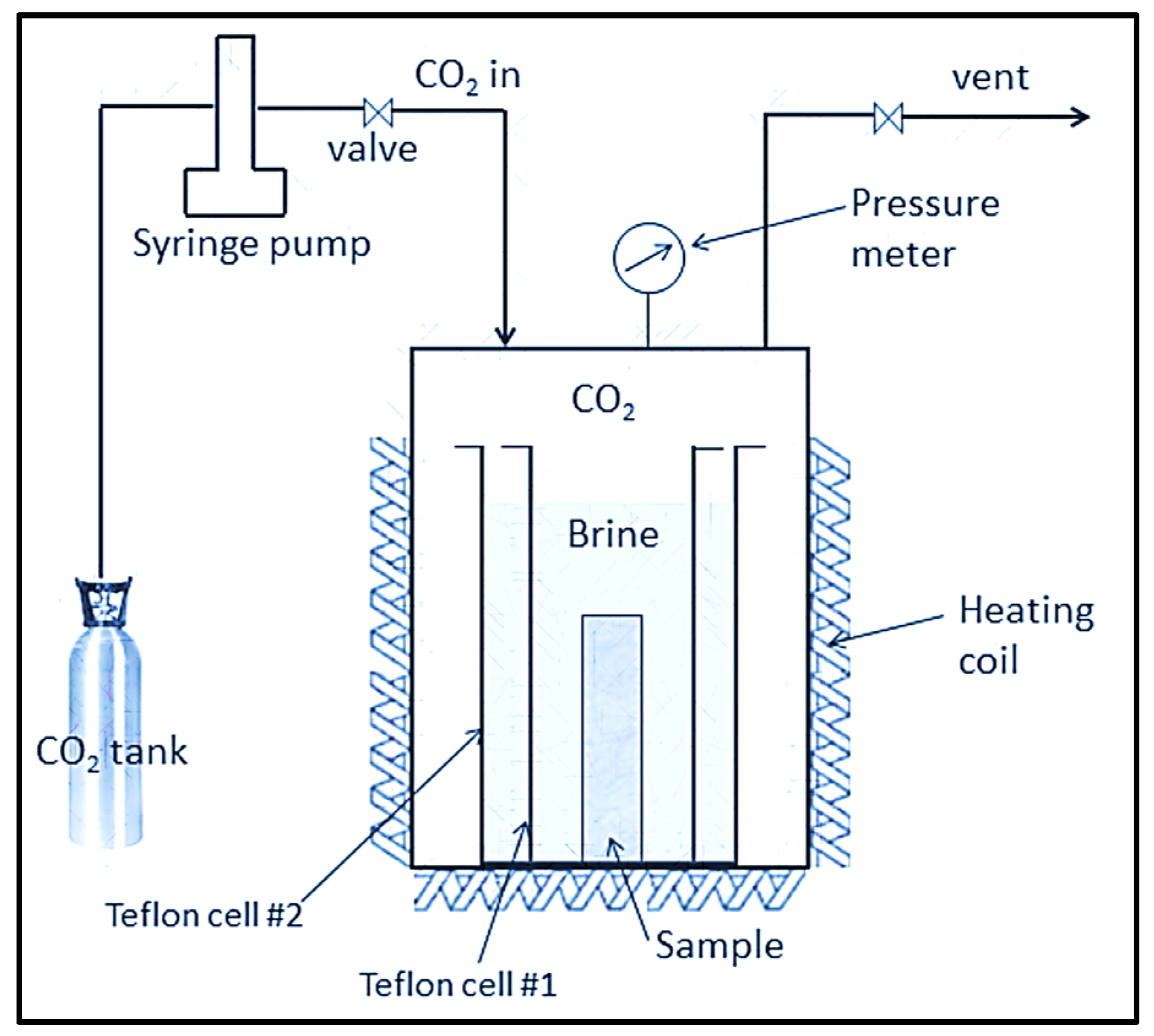
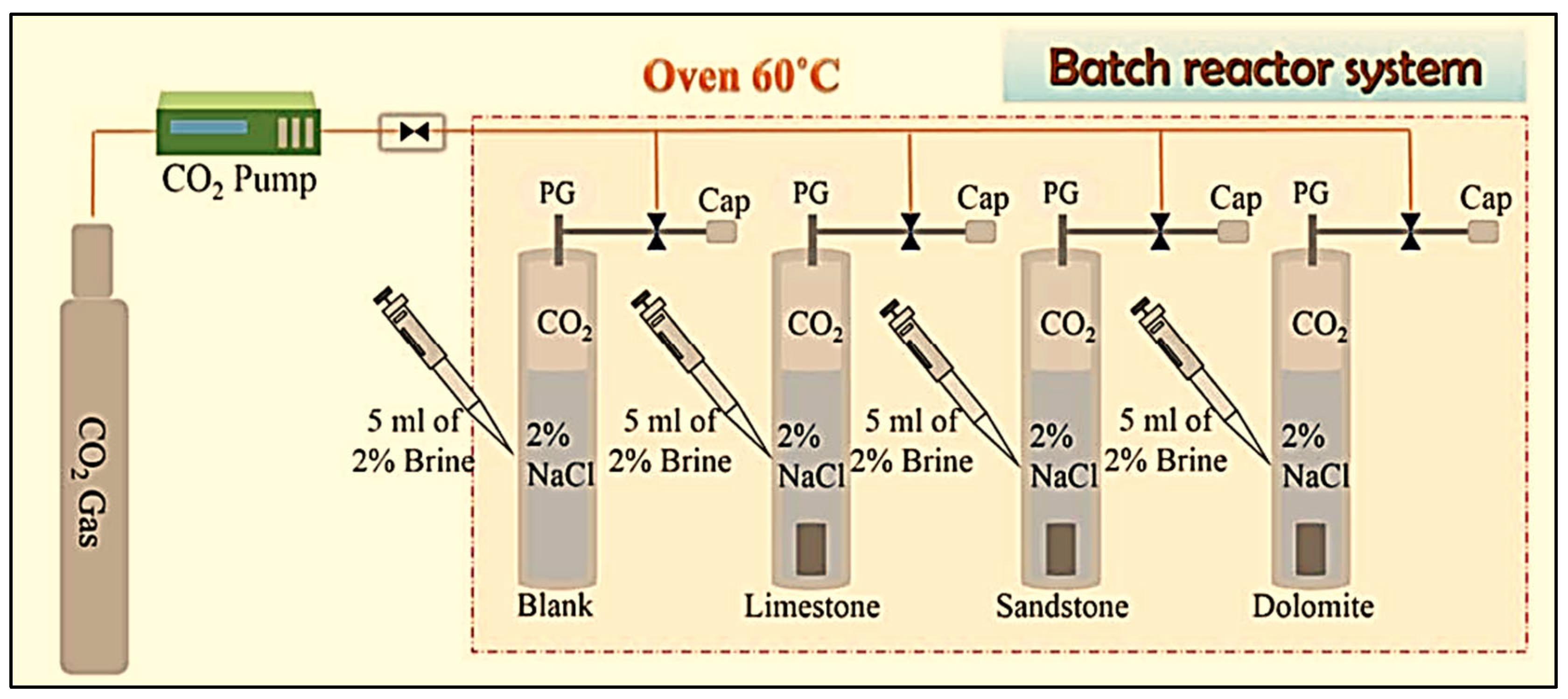
In Figure 21, the static reactor system is depicted for both one-month and six-month durations. Operating at approximately 55 °C and a pressure of 4.08 MPa, the system facilitates interactions between CO2 and brine. The outcomes of these interactions revealed alterations in permeability, porosity, dissolution, and pore structure [42]. The batch experiment revealed various mineral dissolution patterns, resulting in increased surface area and enhanced dissolution rates, as illustrated in Figure 22 [87]. Mandalaparty [88] elucidated the chemical reactions occurring during CO2–brine–rock interactions through batch experiments. In limestone samples, a notable dissolution occurred without any precipitation observed. Conversely, sandstone experiments exhibited the precipitation of calcite and kaolinite. A coherent correlation between simulation and laboratory findings was established, using the Geochemist’s Workbench (V3.2.2) for modeling. The lessons learned from a critical review of over 100 references reveal several key insights for understanding geochemical interactions and reactive transport phenomena.
In Appendix A, Table A1 provides a comprehensive overview of detailed studies, analyses, and results from static batch reactor experiments involving various rock types, including sandstone, carbonate, shale, etc.
Table A1 (Appendix A) offers an overview of detailed studies, precise analyses, and conclusive results from static batch reactor experiments involving a diverse range of rock types, including sandstone, carbonate, shale, and more. It not only provides a detailed analysis of the findings but also establishes the scientific criteria with utmost precision, mentioning the critical parameters that are indispensable for the geochemical and geochemistry of CO2–brine–rock interactions in the context of CCS. Table A1 provides a detailed analysis of numerous experimental studies, each delving into the intricate and multifaceted effects of CO2 exposure on various geological formations. These studies, conducted on formations such as the Lower Tuscaloosa Formation, Vermillion Sandstone, and Knox County, have revealed significant changes in permeability (K) and porosity (φ) over a span of 180 days. For instance, the Vermillion Sandstone experienced a 50% decrease in K. The high-pressure high-temperature (HPHT) reactor studies on sandstones demonstrated changes in mineral concentrations leading to silicate precipitation. Studies on Selma chalk indicated its potential as a CO2 storage seal due to stable permeability, while basalt samples showed increased porosity and decreased rigidity from CO2–water–rock reactions. Lithic sandstone and calcareous mudstone in deep coal seams showed significant chemical reactivity, forming minerals that enhance CO2 containment security and prevent ground pollution. Mafic rock studies revealed substantial increases in rock hardness and the Young’s modulus post-CO2 exposure, although porosity decreased. These findings collectively highlight the complex and dynamic interactions between CO2 and various rock types, underscoring the importance of mineral dissolution and precipitation in altering rock properties, an essential aspect of geological carbon storage (for additional details, see Table A1 in Appendix A).

3.2. Laboratory-Scale Core Flooding Experiments of CO2–Brine–Rock Interaction for Carbon Storage

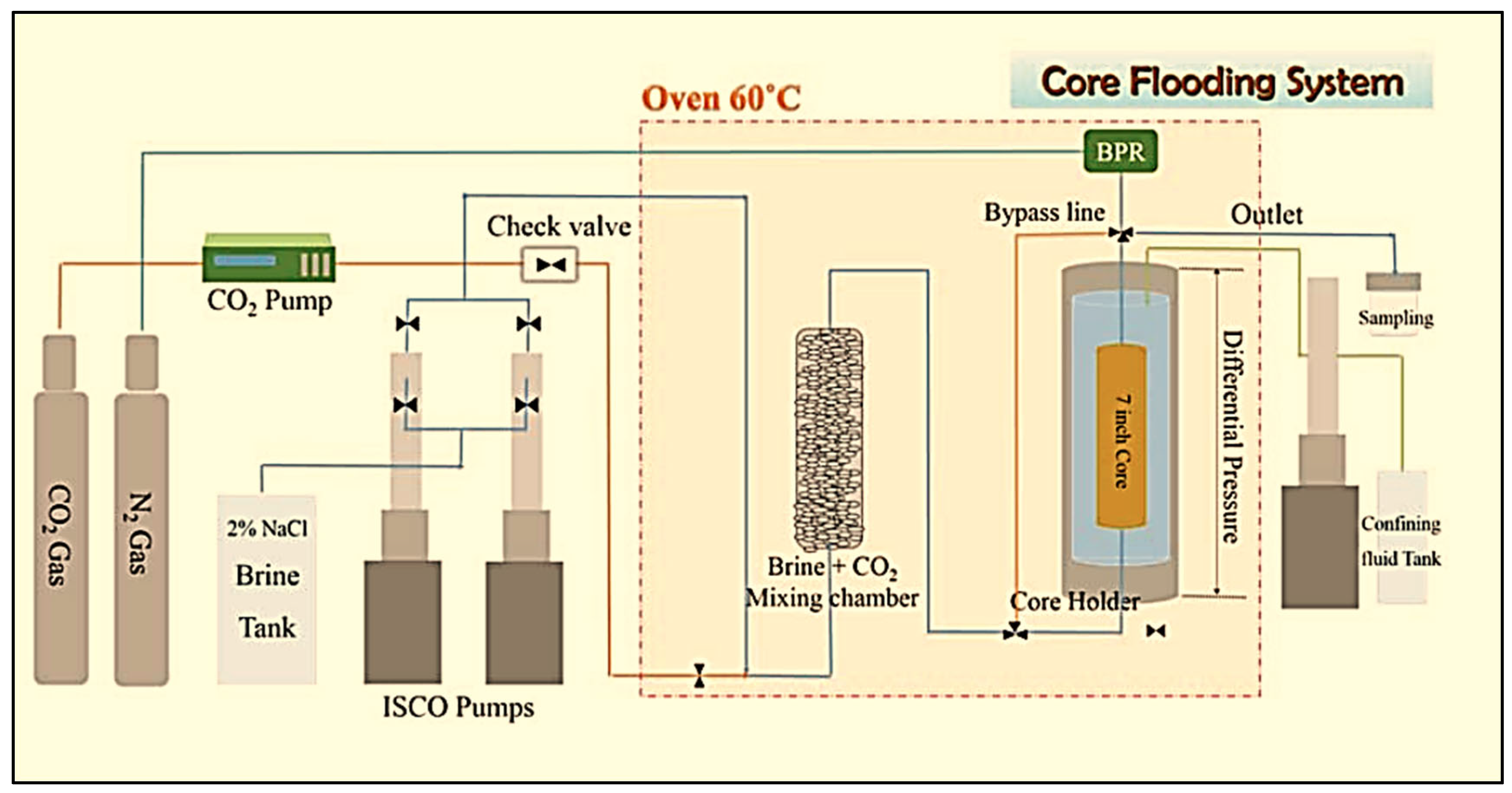
The author [87] employed the core flooding system depicted in Figure 23, which maintained a constant brine flow rate for each sandstone, limestone, and dolomite laboratory experiment. The CO2 flow rates varied, with rates of 2.82 mL/min and 1.41 mL/min for sandstone, 1.4 mL/min for limestone, and 0.71 mL/min for dolomite. The findings underscored the significance of iron chemistry in sandstone for CO2 sequestration and the dissolution and wormhole formation observed in limestone and dolomite. The dissolution of iron-bearing minerals contributed to increased porosity. These results were effectively modeled using reactive transport simulators such as TOUGHREACT [87]. Table A2 (Appendix A) offers a detailed account of laboratory-scale core flooding experiments of CO2–brine–rock interactions for carbon storage, with each one being a significant piece of the puzzle in our understanding of the effects of CO2 injection under different temperatures and pressure conditions. In sandstone, experiments revealed minimal gravity override and provided significant insights into scCO2 dissolution and mobility. Studies on calcite-rich rocks like Savonnières and carbonate samples highlighted the risks of injectivity reduction near wellbores due to calcite dissolution and precipitation, with an observable wormhole formation and mechanical property changes. The core flooding experiments in the Asmari Formation (dolomite–calcite) demonstrated significant permeability and porosity reductions, suggesting safe CO2 storage potential in highly fractured formations. However, long-term reactions led to mineral precipitation and increased ion concentrations in pore fluids. The siltstone study emphasized the critical impact of salinity on caprock permeability, showing significant reductions due to evaporite deposition, thus illustrating the importance of brine chemistry in CO2 storage processes. These findings underscore the intricate geochemical interactions and mechanical alterations induced by CO2 injection, which are crucial for optimizing geological carbon sequestration strategies (for additional details, see Table A2 in Appendix A).
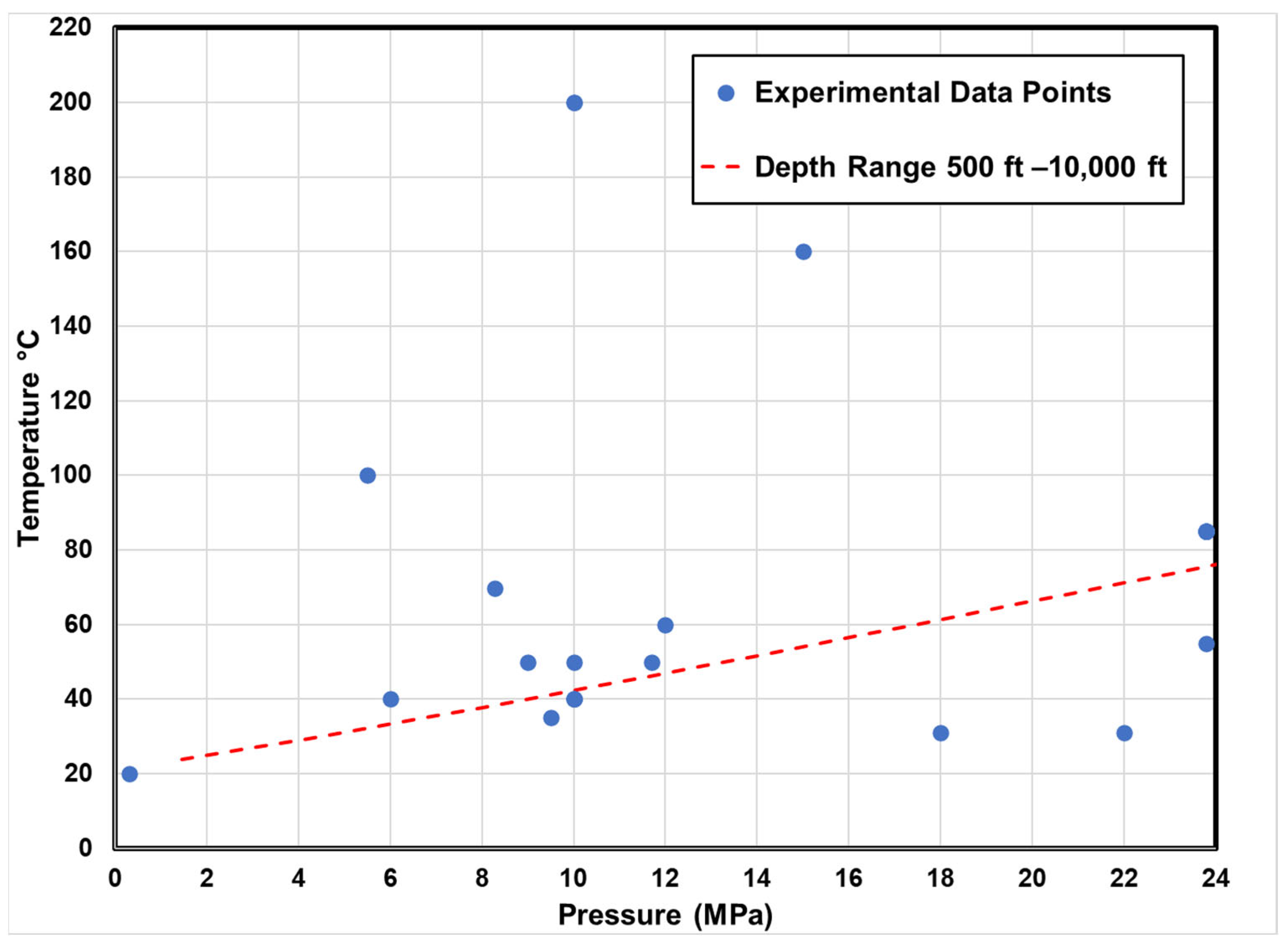
Figure 24, which is based on the data in Table A1 and Table A2 (Appendix A), is a summary of all pressures and temperatures used in laboratory studies. It includes 23 data points (only 16 shown here) from core flooding experiments as well as static reactors, static batch reactors, HPHT reactors, and static systems (in situ condition). The graph shows the range of reservoir depths covered in the experimental studies (500 ft to 10,000 ft). The MPD results in these studies show the most coverage for reservoirs at depths ranging from 2000 to 5000 ft. The data for higher temperatures are found to generally be at pressures below the normal hydrostatic pressures.
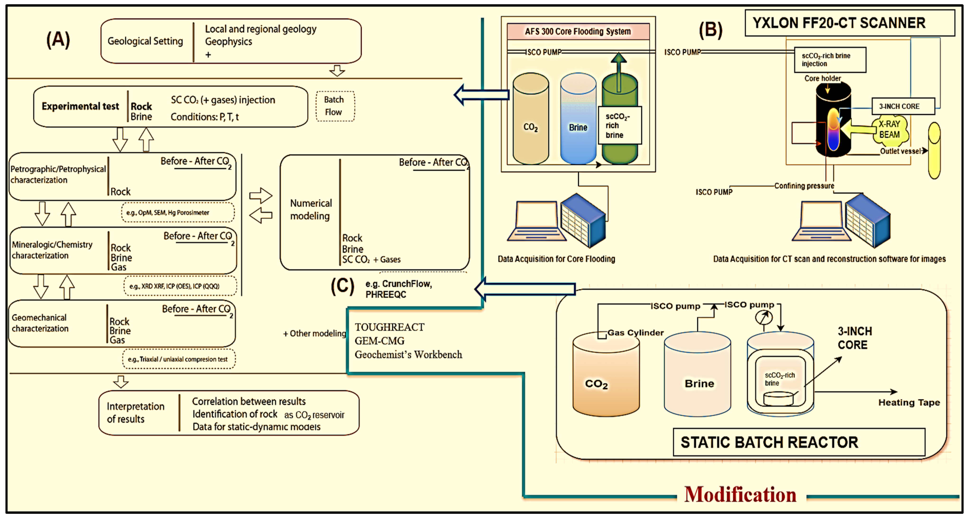
Figure 25 shows the experimental methodology and operational framework. The workflow comprises five pivotal components:
(1)
Petrophysical characterization involving helium porosimeter and ultra-permeability assessments.
(2)
Analytical chemistry processes, including XRD and SEM.
(3)
Utilization of a static batch reactor for investigating long-term CO2 storage.
(4)
AFS 300 core flooding experiments to observe chemical changes using the Comet Yxlon FF20 industrial CT scanner.
(5)
Implementing reactive transport modeling to explore long-term CO2 storage dynamics over 1 to 10,000 years using simulation, elucidating the processes governing long-term storage and sequestration integrity.
Few studies have explored the dielectric constant or dielectric permittivity in CO2–water–porous media, making this a largely uncharted area of research. Our investigation focuses on the dielectric constant, a vital rock property, and dielectric permittivity, defined as “the product of vacuum permittivity and relative permittivity” [91]. Rabiu et al. (2020) were pioneers in examining dielectric permittivity interactions between CO2, water, and basalt for carbon storage. Their seminal work found that bulk dielectric permittivity increased with CO2 injection, while bulk electrical conductivity initially remained unchanged but later increased. This was attributed to the time-dependent dissolution of CO2 in water. Consequently, pH, bulk dielectric permittivity, and bulk electrical conductivity are crucial for CO2 monitoring [92]. Based on the above understanding, these can also affect the geochemical and mineralogical interactions pre- and post-CO2–brine–rock reactions at the static batch reactor and how these changes occurred based on the dielectric permittivity and dielectric constant after complete exposure of scCO2 as a time-dependent parameter. Future research direction will be based on the dielectric constant or dielectric permittivity in terms of MPD (mineralization, precipitation, and dissolution).

4. Simulation Studies of CO2–Brine–Rock Interaction for Carbon Storage

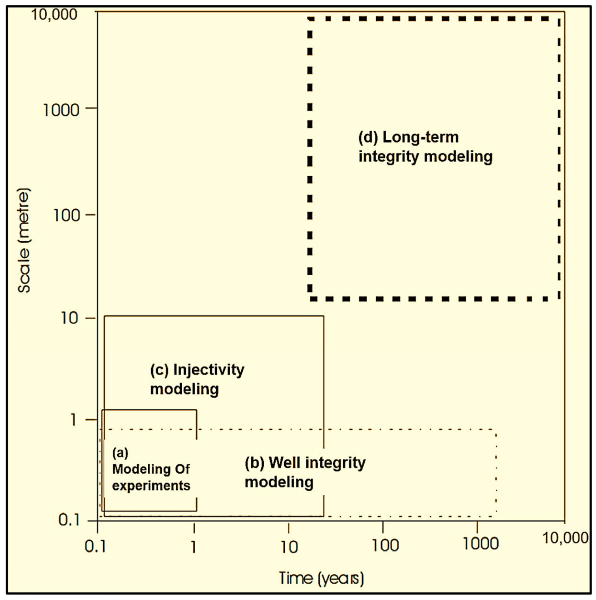
Geochemical and solute transport modeling is a practical tool for ensuring the long-term security of CO2 storage. As illustrated in Figure 26, this modeling comprises four key components: (1) modeling of CO2 experiments, (2) long-term CO2 integrity modeling, (3) CO2 injectivity modeling, and (4) well integrity modeling. These components, measured in meters and years, are essential for understanding the fate of injected CO2 and its effects on chemical and physical properties. This includes residual CO2 trapping, structural tapping, mineral tapping, and dissolution trapping. Various reactive transport simulators are available to monitor these changes over extended periods. Researchers frequently utilize sedimentary rock formations, such as depleted reservoirs (oil and gas) and saline aquifers, for CO2 storage and monitoring [17]. Petroleum reservoirs, in particular, offer the advantage of existing subsurface infrastructure for CO2 storage and monitoring [93].
This section provides a comparative overview and introduction to the principles and performance of different simulation research tools used in CO2–brine–rock interactions for CO2 sequestration for reactive transport simulators, as discussed in Table 1 and Table 2. The performance of the various reactive transport simulators is based on previous research, as detailed in Table 2.
Table 1. Comparative overview of different reactive transport simulators for CO2–brine–rock interactions for geochemical modeling for CO2 sequestration.
SimulatorsComparative Overview
TOUGHREACT V4.13-OMP [94]
  • TOUGHREACT was developed by the Energy Geoscience division of Lawrence Berkely National Laboratory, University of California, Berkeley.
  • TOUGHREACT V4.13-OMP is a simulator used for multiphase reactive transport. It is also used for other purposes, but here, it is focused on geological carbon sequestration.
  • The Treactv413omp_eco2n module of TOUGHREACT is used for 1D and 2D cases for CO2 sequestration in a deep saline formation (executable version of the software).
  • TOUGHREACT is written in FORTRAN 77 with FORTRAN-90 extensions.
Geochemist’s Workbench (GWB 2023) [95,96]
  • It includes C++, Fortran 90, and Python wrappers.
  • GWB software was initially developed by the University of Illinois Urbana-Champaign. It is currently developed by Aqueous Solutions LLC.
  • The software has an exemplary user interface that can do many things, such as reactive transport modeling, including X1t and X2t (1D and 2D), phase diagrams, equilibrium and kinetic reactions, graphics and animation, and more.
PHREEQC (V3) [97]
  • PHREEQC is developed by the US Geological Survey for geochemical modeling and chemical reactions.
  • It is written in the C++ programming language.
CRUNCHFLOW (2009) [98]
  • It was developed by Carl I. Steefel, the Earth science division of Lawrence Berkely lab.
  • It is written in Fortran programming language.
  • It is used for multicomponent reactive flow and transport modeling, including aqueous kinetics, geochemical conditions, diffusion, dispersion, etc.
GEM-CMG (2023.40)
  • GEM is a reservoir simulation software package from the Computer Modeling Group, Canada.
  • It has geochemistry modeling options, including a kinetics reaction model (mineral precipitation and dissolution reactions).
Previous studies on injecting supercritical CO2 (scCO2) near wellbore regions for CO2 storage have produced significant findings. Utilizing THC (thermal, hydraulic, chemical) codes, these studies comprehensively modeled the interactions associated with injecting millions of tons of CO2 per year, focusing on processes occurring near the wellbore region. Notably, researchers employed TOUGHREACT to investigate the critical impact of the near wellbore region on the injectivity of scCO2, as illustrated in Figure 27 [17,18,99].
Table 2 offers insight into the role of geochemical reactions in CO2 multiphase reactive transport. It explains the mechanisms behind chemical reactions in long-term CO2 storage, CO2 storage processes, leakage scenarios, and multiphase displacement (MPD) phenomena. These reactions are analyzed using reactive transport software such as TOUGHREACT V4.13-OMP, GWB 2023, CRUNCHFLOW (2009), GEM-CMG (2023.40), and PHREEQC (V3).
Table 2. Summary of previous research on the reactive transport simulator for CO2–brine–rock interactions for CO2 sequestration.
SampleSimulatorResearch Findings
Sandstone and Limestone [100]Numerical simulation (GEM module of CMG)Geochemical activity significantly impacts limestone, causing a 16.12% increase in porosity. Due to chemical activity, both limestone and sandstone experience decreased reservoir strength during the injection period. The maximum subsidence after 500 years is 0.0017 m in sandstone and 0.033 m in limestone, attributed to geochemical activities.
Sand and Shale [101]2D radial reservoir model for two-phase flow (TOUGHREACT)Following 10,000 years, 95% of the CO2 dissolves in the brine, while minerals absorb 5%. The mineralogy of the sand and shale is comprehensively characterized utilizing kinetics based on transition state theory.
Carbonate Rock [102]GEM-GHG [103,104] After 10,000 years, the percentage of CO2 trapped in minerals ranges from 40% to 100%, depending on the initial mineralogy. The rock mineralogy is determined using kinetics based on transition state theory.
Cap Rock [105]PHREEQC (V2.6) The alteration in porosity in the cap rock is insignificant, with a minor reduction in φ being modeled overall, except at the interface between the reservoir and cap rock after 3000 years. The entire cap rock mineralogy is assessed using kinetics based on transition state theory reactions.
Lithic Sandstone and Calcareous Mudstone (deep coal seams) [106]TOUGHREACTGeochemical simulation can partially reflect the dissolution and precipitation state of minerals, but it only partially aligns with experimental results. Ensuring reliability requires incorporating the actual formation’s physical properties and the rocks’ thermodynamic parameters into the simulation.
Calcite [34]PHREEQC (V3)This study investigated the geochemical perspective of CO2/calcite/brine wettability, considering pressure, temperature, and salinity effects through surface complexation modeling. The findings indicate that pressure, temperature, and salinity influence calcite surface species concentrations, surface potential, and disjoining pressure, impacting CO2-wetness and water-wetness dynamics.
Eagle Ford and Mancos Shales [107]PHREEQC (V3)A one-dimensional reactive transport model using PHREEQC simulated CO2–shale interaction. Equilibrium and kinetic models at 70 °C and 117 atm, calibrated with shale core data from Eagle Ford and Mancos fields, revealed CO2 injection triggering mineral dissolution and precipitation. The models emphasized the effectiveness of mineral trapping and significant changes occurring between 10 and 100 years. The results contribute to understanding the mineral evolution in CO2–shale interaction, but further studies are needed to address field-scale uncertainties.
Shihezi Formation [108]TOUGHREACT V4.12-OMP (10, 20, 30, 300, 500 and 1000 years)Numerical simulations of CO2–brine–rock interactions in the Shihezi Formation indicate K-feldspar and albite dissolution, while calcite and quartz show dissolution and precipitation patterns. Despite a low interaction rate, this proves an ideal geological storage mechanism, influencing petrophysical parameters, minimizing leakage risk, and enhancing CO2 mineralization.
Carbonate [109]PHREEQC (V3)This study utilized experiments that included dynamics and static and PHREEQC geochemical modeling to analyze CO2–brine–rock interaction in carbonate rocks. The findings revealed intensified CO2 dissolution, pressure-independent surface CO2 loading on calcite and dolomite, and minimal influence exchange of ions on CO2 storage in these minerals.
Gabbro-Anorthosite [110]CRUNCHFLOW (2009)In laboratory experiments on a gabbro-anorthosite sample, the potential for CO2 mineral carbonation was assessed under realistic pressure and temperature conditions using seawater. Geochemical modeling in CrunchFlow successfully replicated the experimental observations, revealing increased iron, magnesium, and calcium concentrations during dissolution (Stage I) and signs of carbonation during subsaturation (Stage II). The study suggests mineral carbonation potential in the Torrão–Odivelas Massif, emphasizing further research to upscale the findings to field scale for effective CO2 emissions reduction.
Shale [111]Geochemist’s WorkbenchGeochemical modeling provides calcite dissolution, an increase in shale porosity because of overall shale brine CO2 interaction, and a pH drop due to desorption of tracer elements, and calcite is the main factor in controlling the mobilization of trace elements.

5. Discussion

This research highlights the gap in predicting the long-term changes of the CO2–brine–rock interaction under laboratory and simulation studies using geochemical reactive transport simulators, such as TOUGHREACT, Geochemist’s Workbench, and PHREEQC. The primary focus of our review is to quantify the recent advancement in carbon storage technology, which is crucial for the environmental impact and which is one aspect of carbon storage towards net-zero technology in the petroleum industry. Building on an extensive literature review of recent advances in geochemical and mineralogical studies on CO2–brine–rock interactions for CO2 sequestration, we aimed to monitor and identify the optimal parameters for comprehensive understanding suitable for long-term carbon storage. These findings are significant and of utmost importance to our field of carbon capture and storage (CCS) as they contribute to our collective efforts in CO2 sequestration.
Geochemical changes such as mineralization, precipitation, and dissolution (MPD) are crucial for carbon storage. Monitoring these processes is vital for understanding long-term carbon storage and ensuring its security. As discussed in Appendix A, Table A1 and Table A2, and Table 2, significant changes in permeability, porosity, calcite precipitation, mineral dissolution, and feldspar dissolution alter the pore structure of the core samples.
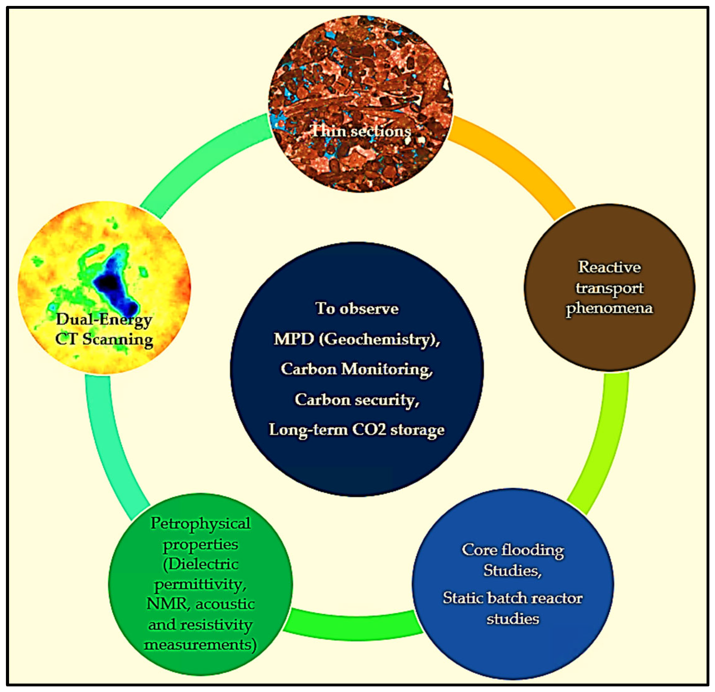
The five most vital experimental and simulation techniques for understanding the MPD are shown in Figure 28. The findings of this research are significant, providing a comprehensive understanding of various aspects of reactive transport mechanisms, including permeability, porosity, and mineralogical changes, utilizing in situ visualization with a CT scanner.
  • Dual-energy CT scanning.
  • Thin sections.
  • Core flooding and batch reactor experiments.
  • Petrophysical properties include dielectric permittivity, NMR measurements, and acoustic and resistivity measurements.
  • Reactive transport phenomena modeling.

6. Conclusions

Based on a review spanning the last 25 years of geochemical studies on CO2–brine–rock interactions, several essential parameters, considerations, and future research gaps are documented.
  • CO2–Brine–Rock interactions can create MPD (mineralization, precipitation, dissolution), permeability, and porosity changes based on the types of reservoir rocks and effects on the reactive transport phenomena for long-term CO2 storage.
  • Researchers used various simulators for geochemical reactions, including TOUGHREACT, PHREEQC, CRUNCHFLOW, and the GEM module of CMG. While the Geochemist’s Workbench is an exemplary interface for CO2 sequestration, it must be utilized more systematically. Geochemist’s Workbench is recommended to comprehensively understand CO2 storage over different time scales (e.g., 10, 20, 30, and up to 10,000 years), considering MPD, multiphase flow, permeability, porosity, changes, and reactive transport mechanisms.
  • Rapid carbonate dissolution can corrode caprock, compromise fault seals, lead to equipment leakage, and affect CO2 security.
  • Limited research has utilized industrial/micro-CT scanners. We can examine MPD interactions between CO2, brine, and rock for short- and long-term CO2 storage by employing industrial/micro-CT scanners with dual-energy techniques and analyzing cuttings or chips using micro-CT scanners.
  • The effects of pressure, temperature, and salinity on CO2–brine–rock wettability and interfacial tension for long-term CO2 storage outcomes are unclear, including laboratory studies such as dynamic core flooding, static batch reactor experiments, and simulation studies, such as geochemical reactive transport modeling.
  • Lab studies show that after CO2 storage, there is a reduction in permeability and porosity in fractured reservoirs [112]. This indicates the potential applicability of CO2 storage in fractured shale and limestone reservoirs. The chemical reactions play a crucial role in sealing fractures by reducing permeability. Further studies are required, and the topic’s applicability may extend to the Permian Basin for more CO2 storage security, monitoring, and integrity. Abel [113] estimated significant carbon sequestration capacities in the Permian Basin of west Texas and southeastern New Mexico. The study focused on forming solid carbonates with cations from produced waters (surface mineralization) and storing CO2 dissolved in produced waters (solubility trapping).
  • Most importantly, investigating the changes before and after CO2–brine–rock interactions, particularly considering the influence of the dielectric constant, is crucial. However, research on the dielectric constant and dielectric dispersion remains limited. The dielectric constant, or permittivity, reflects a material’s electrical polarizability [91]. It is linked to macroscopic properties such as solubility, reaction rate constants, and microscopic phenomena [114]. Therefore, further attention to the rock’s dielectric constant before and after interactions with CO2 and brine is warranted, as it may significantly affect the rock’s geochemical and mineralogical structure.
  • Several gaps exist in understanding Péclet and Damköhler Numbers concerning wormhole formation and propagation during scCO2 injection within various core types. Both Péclet and Damköhler Numbers exhibit an increase during these processes. Further comprehensive investigations are required, mainly focusing on low Damköhler numbers and their influence on reactive transport properties [54].
  • There are still gaps in studies involving CT scanners for in situ observation of chemical changes, including MPD, diffusion, dispersion, and alterations at the pore- and grain-level scales.

Author Contributions

Conceptualization, M.N.K. and G.C.T.; methodology, M.N.K. and S.S.; writing—original draft preparation, M.N.K.; validation, M.N.K. and S.S.; writing—review and editing, M.N.K., S.S. and G.C.T.; investigation, M.N.K. and G.C.T.; visualization, M.N.K.; principal supervision and associate supervision, G.C.T. and S.S.; and revision, M.N.K. and S.S. All authors have read and agreed to the published version of the manuscript.

Funding

This research is partially funded by the CCS/CCUS Consortium of the EIP Team and a gift from Avinash Ahuja.

Data Availability Statement

The data presented in this study are openly available in reference numbers from Refs. [1,2,3,4,5,6,7,8,9,10,11,12,13,14,15,16,17,18,19,20,21,22,23,24,25,26,27,28,29,30,31,32,33,34,35,36,37,38,39,40,41,42,43,44,45,46,47,48,49,50,51,52,53,54,55,56,57,58,59,60,61,62,63,64,65,66,67,68,69,70,71,72,73,74,75,76,77,78,79,80,81,82,83,84,85,86,87,88,89,90,91,92,93,94,95,96,97,98,99,100,101,102,103,104,105,106,107,108,109,110,111,112,113,114,115,116,117,118,119,120,121,122,123,124,125].

Acknowledgments

We thank the Energy Industry Partnership https://eipgroup.petro.uh.edu (accessed on 2 July 2024) and GURI lab (Petroleum Engineering) at Cullen College of Engineering at the University of Houston.

Conflicts of Interest

The authors declare no conflicts of interest.

Nomenclature

EIAEnergy Information Administration
AEOAnnual Energy Outlook
MPDMineralization, precipitation, and dissolution
CH4Methane
GHGsGreenhouse gases
GCSGeological carbon sequestration
scCO2Supercritical CO2
CCSCarbon capture and storage
THCCoupled thermal–hydraulic–chemical
SEMScanning electron microscopy
XRDX-ray diffraction
CTComputerized tomography
HPHTHigh-pressure and high-temperature
11C-CO2Carbon 11 carbon dioxide
PETPositron emission tomography
(CaO·SiO2·H2O)Calcium silicate hydrate
Ca(OH)2Calcium hydroxide
CaCO3Calcium carbonate
KPermeability
ΦPorosity
NaClSodium chloride

Appendix A

Table A1. Summary of research findings on the MPD (mineralization, precipitation, and dissolution) on rock types based on static reactor/static batch reactors/HPHT reactors/static system (in situ condition).
SampleTemp (°C)Pressure (Mpa)Experimental SetupResearch Findings
Lower Tuscaloosa Formation [115]8523.8Static System (in situ condition)The exposure time to CO2 was 180 days, resulting in a 7% decrease in φ and a 13% decrease in K due to feldspar dissolution, migration, and secondary mineral precipitation, which collectively altered the pore structure.
Vermillion Sandstone [116]8523.8Static System (in situ condition)The exposure time to CO2 was 180 days, resulting in a 50% decrease in K due to feldspar dissolution, migration, and secondary mineral precipitation, which collectively altered the pore structure of the sandstone.
Knox County [116]8523.8Static System (in situ condition)The exposure time to CO2 was 180 days, resulting in increased K linked to mineral dissolution (most likely feldspar). Mineral precipitation occurred primarily on the sample’s external surface.
Sandstone [117]20010HPHT ReactorDemonstrate that the ankerite dissolution and clay minerals can elevate the Ca2+, Mg2+, and Fe2+ concentration, ultimately leading to silicate precipitation in CO2. Additionally, these processes can induce changes in reservoir φ and K.
Sandstone [36]402–6Reactor ChamberLong-term CO2 reactions in the aquifer result in a 49% pH drop over 1.5 years, forming carbonic acid.
This process leads to significant mineral dissolution, including Ca2+ and quartz, increasing pore fluid concentrations. Consequently, drying-out effects and NaCl crystallization occur within the rock pore space of the aquifer.
Selma Chalk [115] > 90 calcite8523.8Static System (in situ condition)Selma chalk is a promising candidate as a secondary seal with unchanged K over six months.
Limestone [118]200.3Chemical Analysis and Micro-CTThe 15 h experiment, at an injection rate of 100 cc/h, revealed an uneven increase in φ, connectivity, and reactive surface area due to dissolution.
Carbonate [117]20010HPHT ReactorThis finding and other significant results contribute to our understanding of CO2–brine–rock interactions and provide valuable insights for long-term carbon storage.
Carbonate [42] (gypsum and dolomite)5523.8Static Batch ReactorMineral dissolution and precipitation alter the deposit for CO2 storage, enhancing void connectivity. Both minerals dissolved, increasing K. After six months, the total φ slightly decreased from 19.5% to 19.35%.
Calcite and Dolomite [16]6012Chemical AnalysisThis paper summarizes recent work on CO2 exsolution and mineral effects in GCS reservoirs, emphasizing carbon component behavior (CO2 (sc/g), CO2 (aq), HCO3, calcite, and dolomite). The discussion emphasizes the transport mechanisms involving coupled geochemical and two-phase flow processes, addressing their implications for long-term safety. Experimental findings revealed that mineral dissolution affects both capillary pressure and permeability, which are pivotal factors in reservoir flow modeling.
Basalt (Auckland volcanic) [119]1005.5Reactor ChamberIn a 140-day study on basalt samples, CO2–water–rock reactions increased φ and reduced rigidity due to dissolution; secondary mineral phases formed, including chemically zoned ankerites and aluminosilicates, creating new pores. Basalts with higher initial φ and volcanic glass content exhibited a 15.3% φ increase and a threefold K increase, suggesting potential impacts in CO2 sequestration scenarios.
Lower Tuscaloosa Sandstone [120]8523.8Static ReactorAn experimental study investigated the geochemical CO2–brine–rock interactions under geologic CO2 storage conditions in a static reaction system to probe potential changes. The permeability of the sandstone formation was observed to decrease.
Marine Shale (primary sealing formation) [120]8523.8Static ReactorMarine shale permeability increased after CO2 exposure, impacting primary seal integrity in CO2 storage. The change is attributed to reactive mineral composition, sample heterogeneity, and delamination, with altered shale permeability being observed to be 1000 times less than sandstone.
Lithic Sandstone and Calcareous Mudstone (deep coal seams) [106]16015ReactorIn deep coal seam CO2 storage, a 12-day experimental study revealed that cap rock actively participates in crucial chemical reactions for geological CO2 sequestration. Alterations in lithic sandstone include significant silicate dissolution, while calcareous mudstone exhibits higher reactivity, forming dolomite, siderite, illite, and chlorite. The formation of clay minerals in the cap rock reduces φ, enhancing CO2 containment security and preventing groundwater pollution.
Mafic Rock
(outcrops) [121]
69.88.27Batch ReactorCarbon mineralization in mafic rocks is assessed through experiments on rock characteristics, mineralogy, pore structure, and geomechanics pre- and post-CO2 exposure. The results reveal reactivity with mafic mineral dissolution, new carbonate precipitation, reduced φ (2.2% to 4.5%), and K reaching the measurement limit. Surface rock hardness and Young’s modulus notably increase, with a maximum of 903% and 91% in one sample. An indirect correlation between φ and rock hardness/Young’s modulus is observed, while Poisson’s ratio shows no change after CO2 interaction.
Table A2. Summary of research findings on the MPD (mineralization, precipitation, and dissolution) on rock types based on dynamic core flooding systems.
SampleTemp (°C)Pressure (Mpa)Experimental SetupResearch Findings
Sandstone [122]4010Core FloodingThe CT images of CO2 saturation reveal no significant evidence of gravity override during CO2 injection, even at the relatively low injection rate of 0.1 cc/min.
Sandstone [123]4010Core FloodingA 1D model was developed to simulate the core flooding test performed on the Berea core. Efforts were made to match the evolution of mean CO2 saturation profiles during injection, covering rates from 0.1 cc/min to 4.5 cc/min.
Sandstone [124]4010Core FloodingAn experimental setup was established to investigate the scCO2 dissolution and the transfer of dissolved CO2 in mobile water within (low-K) cores. The experiments were conducted at a flow rate of 1.0 mL/min over 37 h.
Savonnières [49] > 97 Calcite5011.7Core FloodingAt a rate of 0.4 mL/h, the continuous decrease in injectivity in the samples due to the dissolution and precipitation of calcite poses a greater risk, mainly if these processes occur near the wellbore, leading to reduced injectivity and potential shutdown of the CCS operation.
Carbonate [54] > 97% Calcite509Core FloodingAt a flow rate of Q = 1.667 × 10⁻⁹ m3/s and under relatively high Péclet and Damköhler numbers, we observe wormhole formation and propagation, accompanied by alterations in K and φ resulting from dissolution and precipitation.
Savonnières [37] > 97 Calcite5010Core FloodingAt a formation water pH of 3 to 4, chemical reactions impact mechanical properties, leading to increased K and φ. In limestone, these reactions weaken the consolidated area and vice versa, with an injection rate of 0.5 mL/min.
Dolomite–Calcite [112]3118 and 22Core FloodingCO2 sequestration in the Asmari Formation at 1 mL/min and 2 mL/min for 2 and 4 weeks significantly alters geochemical properties, impacting the mineralogical structure. K decreases from 51.8 to 15.06 mD with a φ drop from 22.90 to 15.56. This finding suggests that formations (highly fractured) can safely store CO2, expanding storage locations globally. Long-term CO2 reactions induce dry-out effects and precipitation of NaCl in the pore space of aquifers, increasing the concentration of Na+ from 7300 to 9000 mg/L, with increments of K+ and Mg+ in the pore fluid.
Siltstone [125]358.5–9.5Core FloodingThe study investigates the impact of salinity levels in formation fluid on siltstone caprock K during scCO2 dominant advective flow. Siltstone caprock samples, saturated with synthetic brines resembling natural fluids, underwent scCO2 K experiments. The results reveal a significant reduction in scCO2 K at high salinity concentrations, attributed to evaporite deposition in rock pores, dependent on brine elemental concentration and caprock–brine interaction, known as the CO2 dry-out phenomenon.

References

  1. US Energy Information Administration. Annual Energy Outlook 2023: Narrative. 2023. Available online: https://www.eia.gov/outlooks/aeo/pdf/AEO2023_narrative.pdf (accessed on 2 July 2024).
  2. Davis, S.J.; Lewis, N.S.; Shaner, M.; Aggarwal, S.; Arent, D.; Azevedo, I.L.; Benson, S.M.; Bradley, T.; Brouwer, J.; Chiang, Y.M.; et al. Net-Zero Emissions Energy Systems. Science 2018, 360, eaas9793. [Google Scholar] [CrossRef]
  3. Ganesh, T.; Bose, S.; Selveindran, A. Carbon Storage Focused Reservoir Management: A Practical Example to Respond to Climate Change. In Proceedings of the Future Technologies Conference; Springer Nature: Cham, Switzerland, 2023. [Google Scholar]
  4. IPCC. Climate Change 2023: Synthesis Report; Lee, H., Romero, J., Eds.; Contribution of Working Groups I, II and III to the Sixth Assessment Report of the Intergovernmental Panel on Climate Change; IPCC: Geneva, Switzerland, 2023; pp. 35–115. [Google Scholar] [CrossRef]
  5. Ali, F.; Mohamed, S.M.; Soliman, Y. Limitations and Fallacies of Carbon Capture and Storage (CCS) and Impact on Oil and Gas Production. In Proceedings of the SPE Annual Technical Conference and Exhibition, San Antonio, TX, USA, 16–18 October 2023. [Google Scholar] [CrossRef]
  6. Ajayi, T.; Gomes, J.S.; Bera, A. A Review of CO2 Storage in Geological Formations Emphasizing Modeling, Monitoring and Capacity Estimation Approaches. Pet Sci. 2019, 16, 1028–1063. [Google Scholar] [CrossRef]
  7. IPCC. 2005: IPCC Special Report on Carbon Dioxide Capture and Storage; Metz, B., Davidson, O., de Coninck, H.C., Loos, M., Meyer, L.A., Eds.; Prepared by Working Group III of the Intergovernmental Panel on Climate Change; Cambridge University Press: Cambridge, UK; New York, NY, USA, 2005; 442p. [Google Scholar]
  8. Zhao, X.; Liao, X.; Wang, W.; Chen, C.; Rui, Z.; Wang, H. The CO2 Storage Capacity Evaluation: Methodology and Determination of Key Factors. J. Energy Inst. 2014, 87, 297–305. [Google Scholar] [CrossRef]
  9. CO2 Trapping Mechanisms. Available online: https://www.bigskyco2.org/node/127 (accessed on 2 July 2024).
  10. Al Hameli, F.; Belhaj, H.; Al Dhuhoori, M. CO2 Sequestration Overview in Geological Formations: Trapping Mechanisms Matrix Assessment. Energies 2022, 15, 7805. [Google Scholar] [CrossRef]
  11. Peter, A.; Yang, D.; Eshiet, K.I.I.I.; Sheng, Y. A Review of the Studies on CO2–Brine–Rock Interaction in Geological Storage Process. Geosciences 2022, 12, 168. [Google Scholar] [CrossRef]
  12. Zhang, L.; Wang, Y.; Miao, X.; Gan, M.; Li, X. Geochemistry in Geologic CO2 Utilization and Storage: A Brief Review. Adv. Geo-Energy Res. 2019, 3, 304–313. [Google Scholar] [CrossRef]
  13. DePaolo, D.J.; Cole, D.R. Geochemistry of Geologic Carbon Sequestration: An Overview. Rev. Miner. Geochem. 2013, 77, 1–14. [Google Scholar] [CrossRef]
  14. Jun, Y.S.; Giammar, D.E.; Werth, C.J. Impacts of Geochemical Reactions on Geologic Carbon Sequestration. Environ. Sci. Technol. 2013, 47, 3–8. [Google Scholar] [CrossRef]
  15. Bickle, M. Geological carbon storage. Nat. Geosci. 2009, 2, 815–818. [Google Scholar] [CrossRef]
  16. Xu, R.; Li, R.; Ma, J.; He, D.; Jiang, P. Effect of Mineral Dissolution/Precipitation and CO2 Exsolution on CO2 Transport in Geological Carbon Storage. Acc. Chem. Res. 2017, 50, 2056–2066. [Google Scholar] [CrossRef]
  17. Gaus, I.; Audigane, P.; André, L.; Lions, J.; Jacquemet, N.; Durst, P.; Czernichowski-Lauriol, I.; Azaroual, M. Geochemical and Solute Transport Modelling for CO2 Storage, What to Expect from It? Int. J. Greenh. Gas. Control 2008, 2, 605–625. [Google Scholar] [CrossRef]
  18. André, L.; Audigane, P.; Azaroual, M.; Menjoz, A. Numerical Modeling of Fluid-Rock Chemical Interactions at the Supercritical CO2-Liquid Interface during CO2 Injection into a Carbonate Reservoir, the Dogger Aquifer (Paris Basin, France). Energy Convers. Manag. 2007, 48, 1782–1797. [Google Scholar] [CrossRef]
  19. Olivier, B.; Quisel, N.; Le Gouevec, J. Risk and Safety Evaluation for CO2 Geological Storage. Geotechnol. Sci. Rep. 2007, 9, 27–35. [Google Scholar]
  20. Celia, M.A.; Bachu, S. Geological Sequestration of CO2 Is Leakage Unavoidable and Acceptable. In Proceedings of the 6th International Conference on Greenhouse Gas Control Technologies, Kyoto, Japan, 1–4 October 2002; Elsevier: Amsterdam, The Netherlands, 2003; pp. 477–482. [Google Scholar]
  21. Scherer, G.W.; Celia, M.A.; Prévost, J.-H.; Bachu, S.; Bruant, R.; Duguid, A.; Fuller, R.; Gasda, S.E.; Radonjic, M.; Vichit-Vadakan, W. Leakage of CO2 Through Abandoned Wells. In Carbon Dioxide Capture for Storage in Deep Geologic Formations; Elsevier: Amsterdam, The Netherlands, 2005; pp. 827–848. [Google Scholar]
  22. Hu, Y.; Ray, J.R.; Jun, Y.S. Na+, Ca2+, and Mg2+ in Brines Affect Supercritical CO2-Brine-Biotite Interactions: Ion Exchange, Biotite Dissolution, and Illite Precipitation. Environ. Sci. Technol. 2013, 47, 191–197. [Google Scholar] [CrossRef]
  23. Zhao, L.; Lin, S.; Mendenhall, J.D.; Yuet, P.K.; Blankschtein, D. Molecular Dynamics Investigation of the Various Atomic Force Contributions to the Interfacial Tension at the Supercritical CO2-Water Interface. J. Phys. Chem. B 2011, 115, 6076–6087. [Google Scholar] [CrossRef]
  24. Hu, Y.; Ray, J.R.; Jun, Y.S. Biotite-Brine Interactions under Acidic Hydrothermal Conditions: Fibrous Illite, Goethite, and Kaolinite Formation and Biotite Surface Cracking. Environ. Sci. Technol. 2011, 45, 6175–6180. [Google Scholar] [CrossRef]
  25. Kim, Y.; Wan, J.; Kneafsey, T.J.; Tokunaga, T.K. Dewetting of Silica Surfaces upon Reactions with Supercritical CO2 and Brine: Pore-Scale Studies in Micromodels. Environ. Sci. Technol. 2012, 46, 4228–4235. [Google Scholar] [CrossRef]
  26. Molins, S.; Trebotich, D.; Steefel, C.I.; Shen, C. An Investigation of the Effect of Pore Scale Flow on Average Geochemical Reaction Rates Using Direct Numerical Simulation. Water Resour. Res. 2012, 48, W03527. [Google Scholar] [CrossRef]
  27. Newell, D.L.; Carey, J.W. Experimental Evaluation of Wellbore Integrity along the Cement-Rock Boundary. Environ. Sci. Technol. 2013, 47, 276–282. [Google Scholar] [CrossRef]
  28. Middleton, R.S.; Keating, G.N.; Stauffer, P.H.; Jordan, A.B.; Viswanathan, H.S.; Kang, Q.J.; Carey, J.W.; Mulkey, M.L.; Sullivan, E.J.; Chu, S.P.; et al. The Cross-Scale Science of CO2 Capture and Storage: From Pore Scale to Regional Scale. Energy Environ. Sci. 2012, 5, 7328–7345. [Google Scholar] [CrossRef]
  29. Birkholzer, J.T.; Zhou, Q. Basin-Scale Hydrogeologic Impacts of CO2 Storage: Capacity and Regulatory Implications. Int. J. Greenh. Gas Control 2009, 3, 745–756. [Google Scholar] [CrossRef]
  30. Shao, H.; Ray, J.R.; Jun, Y.S. Effects of Salinity and the Extent of Water on Supercritical CO2-Induced Phlogopite Dissolution and Secondary Mineral Formation. Environ. Sci. Technol. 2011, 45, 1737–1743. [Google Scholar] [CrossRef]
  31. Sun, Y.; Li, Q.; Yang, D.; Liu, X. Laboratory core flooding experimental systems for CO2 geosequestration: An updated review over the past decade. J. Rock Mech. Geotech. Eng. 2016, 8, 113–126. [Google Scholar] [CrossRef]
  32. Kampman, N.; Bickle, M.; Wigley, M.; Dubacq, B. Fluid Flow and CO2-Fluid-Mineral Interactions during CO2-Storage in Sedimentary Basins. Chem. Geol. 2014, 369, 22–50. [Google Scholar] [CrossRef]
  33. Gaus, I. Role and Impact of CO2-Rock Interactions during CO2 Storage in Sedimentary Rocks. Int. J. Greenh. Gas Control 2010, 4, 73–89. [Google Scholar] [CrossRef]
  34. Adila, A.S.; Raza, A.; Zhang, Y.; Mahmoud, M.; Arif, M. Geochemical Interactions Among Rock/CO2/Brine Systems: Implications for CO2 Geo-Storage. In Proceedings of the Gas & Oil Technology Showcase and Conference, Dubai, UAE, 13–15 March 2023. [Google Scholar]
  35. Gadikota, G. Carbon Mineralization Pathways for Carbon Capture, Storage and Utilization. Commun. Chem. 2021, 4, 23. [Google Scholar] [CrossRef]
  36. Rathnaweera, T.D.; Ranjith, P.G.; Perera, M.S.A. Experimental Investigation of Geochemical and Mineralogical Effects of CO2 Sequestration on Flow Characteristics of Reservoir Rock in Deep Saline Aquifers. Sci. Rep. 2016, 6, 19362. [Google Scholar] [CrossRef]
  37. Zhang, Y.; Lebedev, M.; Sarmadivaleh, M.; Barifcani, A.; Iglauer, S. SPE-182285-MS Change in Geomechanical Properties of Limestone Due to Supercritical CO2 Injection. In Proceedings of the SPE Asia Pacific Oil & Gas Conference and Exhibition, Perth, Australia, 25–27 October 2016. [Google Scholar]
  38. Benson, S.M.; Cole, D.R. CO2 Sequestration in Deep Sedimentary Formations. Elements 2008, 4, 325–331. [Google Scholar] [CrossRef]
  39. Kharaka, Y.K.; Cole, D.R.; Hovorka, S.D.; Gunter, W.D.; Knauss, K.G.; Freifeld, B.M. Gas-Water-Rock Interactions in Frio Formation Following CO2 Injection: Implications for the Storage of Greenhouse Gases in Sedimentary Basins. Geology 2006, 34, 577–580. [Google Scholar] [CrossRef]
  40. Kharaka, Y.K.; Cole, D.R.; Thordsen, J.J.; Kakouros, E.; Nance, H.S. Gas-Water-Rock Interactions in Sedimentary Basins: CO2 Sequestration in the Frio Formation, Texas, USA. J. Geochem. Explor. 2006, 89, 183–186. [Google Scholar] [CrossRef]
  41. Knauss, K.G.; Johnson, J.W.; Steefel, C.I. Evaluation of the Impact of CO2, Co-Contaminant Gas, Aqueous Fluid and Reservoir Rock Interactions on the Geologic Sequestration of CO2. Chem. Geol. 2005, 217, 339–350. [Google Scholar] [CrossRef]
  42. Soong, Y.; Howard, B.; Haljasmaa, I.; Crandall, D.; Dilmore, R.; Dalton, L.; Wu, Z.; Wang, P.; Gray, M.; Shi, F. CO2/Brine/Rock Interactions in the Cedar Keys-Lawson Formation. Univers. J. Carbon Res. 2023, 1, 48–62. [Google Scholar] [CrossRef]
  43. Azin, R.; Mehrabi, N.; Osfouri, S.; Asgari, M. Experimental Study of CO2—Saline Aquifer-Carbonate Rock Interaction during CO2 Sequestration. Procedia Earth Planet. Sci. 2015, 15, 413–420. [Google Scholar] [CrossRef]
  44. Zhang, Y.; Shi, L.; Ye, Z.; Chen, L.; Yuan, N.; Chen, Y.; Yang, H. Experimental Investigation of Supercritical CO2-Rock-Water Interactions in a Tight Formation with the Pore Scale during CO2-EOR and Sequestration. ACS Omega 2022, 7, 27291–27299. [Google Scholar] [CrossRef]
  45. Cui, G.; Yang, L.; Fang, J.; Qiu, Z.; Wang, Y.; Ren, S. Geochemical Reactions and Their Influence on Petrophysical Properties of Ultra-Low Permeability Oil Reservoirs during Water and CO2 Flooding. J. Pet. Sci. Eng. 2021, 203, 108672. [Google Scholar] [CrossRef]
  46. Gao, Z.; Feng, J.; Cui, J.; Xiaoqi, W.; Chuanmin, Z.; Yuxin, S. Physical simulation and quantitative calculation of increased feldspar dissolution pores in deep reservoirs. Pet. Explor. Dev. 2017, 44, 387–398. [Google Scholar] [CrossRef]
  47. Gledhill, D.K.; Morse, J.W. Calcite Dissolution Kinetics in Na–Ca–Mg–Cl Brines. Geochim. Cosmochim. Acta 2006, 70, 5802–5813. [Google Scholar] [CrossRef]
  48. Marbler, H.; Erickson, K.P.; Schmidt, M.; Lempp, C.; Pöllmann, H. Geomechanical and Geochemical Effects on Sandstones Caused by the Reaction with Supercritical CO2: An Experimental Approach to in Situ Conditions in Deep Geological Reservoirs. Environ. Earth Sci. 2013, 69, 1981–1998. [Google Scholar] [CrossRef]
  49. Raza, A.; Gholami, R.; Sarmadivaleh, M. Feasibility of Limestone Reservoirs as a Carbon Dioxide Storage Site: An Experimental Study. Am. Assoc. Pet. Geol. Bull. 2020, 104, 83–96. [Google Scholar] [CrossRef]
  50. Awolayo, A.N.; Sarma, H.K. SPE-193815-MS Numerical Modeling of Fluid-Rock Interactions During Low-Salinity-Brine-CO2 Flooding in Carbonate Reservoirs. In Proceedings of the SPE Reservoir Simulation Conference, Galveston, TX, USA, 10–11 April 2019. [Google Scholar]
  51. Zhang, Y.; Sarmadivaleh, M.; Lebedev, M.; Barifcani, A.; Rezaee, R.; Testamantia, N.; Iglauer, S. OTC-26470-MS Geo-Mechanical Weakening of Limestone Due to Supercritical CO2 Injection. In Proceedings of the Offshore Technology Conference Asia, Kuala Lumpur, Malaysia, 22–25 March 2016. [Google Scholar]
  52. Seyyedi, M.; Mahmud, H.K.; Ben Verrall, M.; Giwelli, A.; Esteban, L.; Ghasemiziarani, M.; Clennell, B. Pore Structure Changes Occur During CO2 Injection into Carbonate Reservoirs. Sci. Rep. 2020, 10, 3624. [Google Scholar] [CrossRef]
  53. Abdullah, A.-D.; Aljawad, M.S.; Al-Ramadan, M.; Ibrahim, A.F.; Al Majid, M.M.; Al-Yousif, Z.; Al-Yaseri, A. The impact of CO2 saturated brine salinity on wormhole generation and rock geomechanical and petrophysical properties. Geoenergy Sci. Eng. 2024, 233, 212490. [Google Scholar]
  54. Gharbi, O.; Bijeljic, B.; Boek, E.; Blunt, M.J. Changes in Pore Structure and Connectivity Induced by CO2 Injection in Carbonates: A Combined Pore-Scale Approach. Energy Procedia 2013, 37, 5367–5378. [Google Scholar] [CrossRef]
  55. Soulaine, C.; Roman, S.; Kovscek, A.; Tchelepi, H.A. Mineral Dissolution and Wormholing from a Pore-Scale Perspective. J. Fluid Mech. 2017, 827, 457–483. [Google Scholar] [CrossRef]
  56. Szymczak, P.; Ladd, A.J.C. Wormhole Formation in Dissolving Fractures. J. Geophys. Res. Solid Earth 2009, 114, B06203. [Google Scholar] [CrossRef]
  57. Golfier, F.; Zarcone, C.; Bazin, B.; Lenormand, R.; Lasseux, D.; Quintard, M. On the Ability of a Darcy-Scale Model to Capture Wormhole Formation during the Dissolution of a Porous Medium. J. Fluid Mech. 2002, 457, 213–254. [Google Scholar] [CrossRef]
  58. Daccord, G.; Touboul, E.; Lenormand, R.; Schlumberger, D. Carbonate Acidizing: Toward a Quantitative Model of the Wormholing Phenomenon. SPE Prod. Eng. 1989, 4, 63–68. [Google Scholar] [CrossRef]
  59. Bazin, B. From Matrix Acidizing to Acid Fracturing: A Laboratory Evaluation of Acid/Rock Interactions. SPE Prod. Facil. 2001, 16, 22–29. [Google Scholar] [CrossRef]
  60. Egermann, P.; Bekri, S.; Vizika, O. An Integrated Approach to Assess the Petrophysical Properties of Rocks Altered by Rock-Fluid Interactions (CO2 Injection). Petrophysics 2010, 51, SPWLA-2010-v51n1a2. [Google Scholar]
  61. Bekri, S.; Thovert, J.-F.; Adler, P.M. Dissolution and deposition in fractures. Eng. Geol. 1997, 48, 283–308. [Google Scholar] [CrossRef]
  62. Daccord, G.; Lenormand, R.; Lietard, O. Chemical dissolution of a porous medium by a reactive fluid—I. Model for the “wormholing” phenomenon. Chem. Eng. Sci. 1993, 48, 169–178. [Google Scholar] [CrossRef]
  63. Békri, S.; Thovert, J.F.; Adler, P.M. Dissolution of Porous Media. Chem. Eng. Sci. 1995, 50, 2765–2791. [Google Scholar] [CrossRef]
  64. Schechter, R.S.; Gidley, J.L. The Change in Pore Size Distribution from Surface Reactions in Porous Media. AIChE J. 1969, 15, 339–350. [Google Scholar] [CrossRef]
  65. Sarker, M.R.H.; Siddiqui, S. Advances in Micro-CT Based Evaluation of Reservoir Rocks. In Proceedings of the SPE Saudi Arabia Section Technical Symposium, Al-Khobar, Saudi Arabia, 9–11 May 2009. [Google Scholar] [CrossRef]
  66. Wellington, S.L.; Vinegar, H.J. X-ray Computerized Tomography. J. Pet. Technol. 1987, 39, 885–898. [Google Scholar] [CrossRef]
  67. Shameem, S.; Khamees, A.A. Dual-Energy CT-Scanning Applications in Rock Characterization. In Proceedings of the SPE Annual Technical Conference and Exhibition, Houston, TX, USA, 26–29 September 2004. [Google Scholar] [CrossRef]
  68. Siddiqui, S.; Grader, A.S.; Touati, M.; Loermans, A.M.; Funk, J.J. Techniques for Extracting Reliable Density and Porosity Data from Cuttings. In Proceedings of the SPE Annual Technical Conference and Exhibition, Dallas, TX, USA, 9–12 October 2005. [Google Scholar] [CrossRef]
  69. Brattekås, B.; Fernø, M.A.; Haugen, M.; Føyen, T.; Steinsbø, M.; Graue, A.; Brekke, N.; Adamsen, T.C.H.; Rygh, C.B.; Espedal, H. Of Rats and Rocks: Using Pre-Clinical PET Imaging Facilities in Core Analysis. In Proceedings of the 2021 International Symposium of the Society of Core Analysts (SCA 2021), Online, 13–16 September 2021; Volume 366. [Google Scholar]
  70. Brattekås, B.; Haugen, M. Explicit Tracking of CO2-Flow at the Core Scale Using Micro-Positron Emission Tomography (ΜPET). J. Nat. Gas Sci. Eng. 2020, 77, 103268. [Google Scholar] [CrossRef]
  71. Zahasky, C.; Benson, S.M. Using Micro-Positron Emission Tomography to Quantify Single and Multiphase Flow in Heterogeneous Reservoirs. Energy Procedia 2017, 114, 5070–5082. [Google Scholar] [CrossRef]
  72. Jean-Christophe, P.; Benson, S. An experimental study on the influence of sub-core scale heterogeneities on CO2 distribution in reservoir rocks. Transp. Porous Media 2010, 82, 93–109. [Google Scholar]
  73. AlQuraishi, A.A.; Siddiqui, S.; Algadi, O.A. Influence of Heterogeneities on CO2 Sequestration in Potential Saline Formations. In Proceedings of the Offshore Mediterranean Conference and Exhibition, Ravenna, Italy, 29–30 March 2017. [Google Scholar]
  74. Wang, H.; Alvarado, V.; Bagdonas, D.A.; McLaughlin, J.F.; Kaszuba, J.P.; Grana, D.; Campbell, E.; Ng, K. Effect of CO2-Brine-Rock Reactions on Pore Architecture and Permeability in Dolostone: Implications for CO2 Storage and EOR. Int. J. Greenh. Gas Control 2021, 107, 103283. [Google Scholar] [CrossRef]
  75. Rochelle Christopher, A.; Czernichowski-Lauriol, I.; Milodowski, A.E. The impact of chemical reactions on CO2 storage in geological formations: A brief review. Geol. Soc. Lond. Spec. Publ. 2004, 233, 87–106. [Google Scholar] [CrossRef]
  76. Gunter, W.D.; Perkins, E.H.; Hutcheon, I. Aquifer disposal of acid gases: Modelling of water–rock reactions for trapping of acid wastes. Appl. Geochem. 2000, 15, 1085–1095. [Google Scholar] [CrossRef]
  77. Gunter, W.D.; Perkins, E.H. Aquifer Disposal of CO2-Rich Greenhouse Gases: Extension of the Time Scale of Experiment for CO2-Sequestering Reactions by Geochemical Modelling. Mineral. Petrol. 1997, 59, 121–140. [Google Scholar] [CrossRef]
  78. Kharaka, Y.K.; Chudaev, O.V.; Thordsen, J.J.; Armannsson, H.; Breit, G.N.; Evans, W.C.; Keith, T.E.C. Water-Rock Interaction; Routledge: London, UK, 2021; ISBN 9780203734049. [Google Scholar]
  79. Golfier, F.; Bazin, B.; Zarcone, C.; Lernormand, R.; Lasseux, D.; Quintard, M. Acidizing Carbonate Reservoirs: Numerical Modelling of Wormhole Propagation and Comparison to Experiments. In Proceedings of the SPE European Formation Damage Conference, The Hague, The Netherlands, 21–22 May 2001. [Google Scholar] [CrossRef]
  80. Kaszuba, J.P.; Janecky, D.R.; Snow, M.G. Experimental Evaluation of Mixed Fluid Reactions between Supercritical Carbon Dioxide and NaCl Brine: Relevance to the Integrity of a Geologic Carbon Repository. Chem. Geol. 2005, 217, 277–293. [Google Scholar] [CrossRef]
  81. Watson, M.N.; Zwingmann, N.; Lemon, N.M. The Ladbroke Grove-Katnook Carbon Dioxide Natural Laboratory: A Recent CO2 Accumulation in a Lithic Sandstone Reservoir. Energy 2004, 29, 1457–1466. [Google Scholar] [CrossRef]
  82. May, F. Alteration of Wall Rocks by CO2-Rich Water Ascending in Fault Zones: Natural Analogues for Reactions Induced by CO2 Migrating along Faults in Siliciclastic Reservoir and Cap Rocks. Oil Gas Sci. Technol. 2005, 60, 19–32. [Google Scholar] [CrossRef]
  83. Fischer, M.; Botz, R.; Schmidt, M.; Rockenbauch, K.; Garbe-Schönberg, D.; Glodny, J.; Gerling, P.; Littke, R. Origins of CO2 in Permian Carbonate Reservoir Rocks (Zechstein, Ca2) of the NW-German Basin (Lower Saxony). Chem. Geol. 2006, 227, 184–213. [Google Scholar] [CrossRef]
  84. Worden, R.H. Dawsonite Cement in the Triassic Lam Formation, Shabwa Basin, Yemen: A Natural Analogue for a Potential Mineral Product of Subsurface CO2 Storage for Greenhouse Gas Reduction. Mar. Pet. Geol. 2006, 23, 61–77. [Google Scholar] [CrossRef]
  85. Julian, C.; Guo, B.; Bai, P. Continental-Scale Magmatic Carbon Dioxide Seepage Recorded by Dawsonite in the Bowen-Gunnedah-Sydney Basin System, Eastern Australia. SEPM J. Sediment. Res. 1995, 65, 522–530. [Google Scholar] [CrossRef]
  86. Moore, J.; Adams, M.; Allis, R.; Lutz, S.; Rauzi, S. Mineralogical and Geochemical Consequences of the Long-Term Presence of CO2 in Natural Reservoirs: An Example from the Springerville-St. Johns Field, Arizona, and New Mexico, U.S.A. Chem. Geol. 2005, 217, 365–385. [Google Scholar] [CrossRef]
  87. Kweon, H. Mineralogical and Petrophysical Changes in Carbon Dioxide Sequestration. Ph.D. Thesis, University of Utah, Salt Lake City, UT, USA, 2015. [Google Scholar]
  88. Prashanth, M. Reaction Chemistry in Carbon Dioxide Sequestration. Ph.D. Thesis, University of Utah, Salt Lake City, UT, USA, 2012. Available online: https://collections.lib.utah.edu/dl_files/f1/da/f1dab7f252bc6a0d5f8b035d7a0749a8e9f17c21.pdf (accessed on 2 July 2024).
  89. Berrezueta, E.; Kovacs, T.; Herrera-Franco, G.; Mora-Frank, C.; Caicedo-Potosí, J.; Carrion-Mero, P.; Carneiro, J. Laboratory Studies on CO2-Brine-Rock Interaction: An Analysis of Research Trends and Current Knowledge. Int. J. Greenh. Gas Control. 2023, 123, 103842. [Google Scholar] [CrossRef]
  90. Moita, P.; Berrezueta, E.; Abdoulghafour, H.; Beltrame, M.; Pedro, J.; Mirão, J.; Miguel, C.; Galacho, C.; Sitzia, F.; Barrulas, P.; et al. Mineral Carbonation of CO2 in Mafic Plutonic Rocks, II-Laboratory Experiments on Early-Phase Supercritical CO2-Brine-Rock Interactions. Appl. Sci. 2020, 10, 5083. [Google Scholar] [CrossRef]
  91. Schön, J.H. Electrical Properties. In Developments in Petroleum Science; Elsevier: Amsterdam, The Netherlands, 2015; Volume 65, pp. 301–367. ISBN 9780081004043. [Google Scholar]
  92. Rabiu, K.O.; Abidoye, L.K.; Das, D.B. Physico-Chemical and Dielectric Parameters for the Monitoring of Carbon Sequestration in Basalt and Silica Media. Environ. Technol. Innov. 2020, 20, 101052. [Google Scholar] [CrossRef]
  93. Sam, H. An overview of the underground disposal of carbon dioxide. Energy Convers. Manag. 1997, 38, S193–S198. [Google Scholar]
  94. Eric, S.; Spycher, N.; Xu, T.; Zheng, L. TOUGHREACT V4. 13-OMP and TReactMech V1. 0 Geochemical and Reactive-Transport User Guide; Berkeley National Laboratory: Berkeley, CA, USA, 2021; Available online: https://drive.google.com/file/d/1W-O6MqYRtclMkGhv4jdxHK7-l0lXItvy/view (accessed on 2 July 2024).
  95. GWB 2023 Professional. Available online: https://www.gwb.com/professional.php (accessed on 2 July 2024).
  96. GWB Reactive Transport Modeling Guide. Available online: https://www.gwb.com/pdf/GWB/GWBtransport.pdf (accessed on 2 July 2024).
  97. PHREEQC Version 3. Available online: https://www.usgs.gov/software/phreeqc-version-3 (accessed on 2 July 2024).
  98. CrunchFlow Software for Modeling Multicomponent Reactive Flow and Transport: USER’S MANUAL. Available online: https://www.netl.doe.gov/sites/default/files/netl-file/CrunchFlow-Manual.pdf (accessed on 2 July 2024).
  99. Xu, T.; Sonnenthal, E.; Spycher, N.; Pruess, K. TOUGHREACT—A Simulation Program for Non-Isothermal Multiphase Reactive Geochemical Transport in Variably Saturated Geologic Media: Applications to Geothermal Injectivity and CO2 Geological Sequestration. Comput. Geosci. 2006, 32, 145–165. [Google Scholar] [CrossRef]
  100. Raza, A.; Gholami, R.; Rabiei, M.; Rasouli, V.; Rezaee, R.; Fakhari, N. Impact of Geochemical and Geomechanical Changes on CO2 Sequestration Potential in Sandstone and Limestone Aquifers. Greenh. Gases Sci. Technol. 2019, 9, 905–923. [Google Scholar] [CrossRef]
  101. Audigane, P.; Gaus, I.; Czernichowski-Lauriol, I.; Pruess, K.; Xu, T. Two-Dimensional Reactive Transport Modeling of CO2 Injection in a Saline Aquifer at the Sleipner Site, North Sea Two-Dimensional Reactive Transport Modeling of CO2 Injection in a Saline Aquifer at the Sleipner Site. Am. J. Sci. 2007, 307, 974–1008. [Google Scholar] [CrossRef]
  102. Thibeau, S.; Nghiem, L.X.; Ohkuma, H. A Modeling Study of the Role of Selected Minerals in Enhancing CO2 Mineralization During CO2 Aquifer Storage. In Proceedings of the SPE Annual Technical Conference and Exhibition, Anaheim, CA, USA, 11–14 November 2007. [Google Scholar] [CrossRef]
  103. Nghiem, L.; Shrivastavar, A.; Kohse, B.; Sammon, P. Simulation of CO2 EOR and Sequestration Processes with a Geochemical EOS Compositional Simulator. In Proceedings of the Canadian International Petroleum Conference, Calgary, AL, USA, 8–10 June 2004. [Google Scholar] [CrossRef]
  104. Long, N.; Peter, S.; Jim, G.; Ohkuma, H. Modeling CO2 Storage in Aquifers with a Fully-Coupled Geochemical EOS Compositional Simulator. In Proceedings of the SPE/DOE Symposium on Improved Oil Recovery, Tulsa, OK, USA, 17–21 April 2004. [Google Scholar] [CrossRef]
  105. Gaus, I.; Azaroual, M.; Czernichowski-Lauriol, I. Reactive Transport Modelling of the Impact of CO2 Injection on the Clayey Cap Rock at Sleipner (North Sea). Chem. Geol. 2005, 217, 319–337. [Google Scholar] [CrossRef]
  106. Wang, K.; Xu, T.; Wang, F.; Tian, H. Experimental Study of CO2-Brine-Rock Interaction during CO2 Sequestration in Deep Coal Seams. Int. J. Coal Geol. 2016, 154–155, 265–274. [Google Scholar] [CrossRef]
  107. Fatah, A.; Ben, M.H.; Bennour, Z.; Gholami, R.; Hossain, M. Geochemical Modelling of CO2 Interactions with Shale: Kinetics of Mineral Dissolution and Precipitation on Geological Time Scales. Chem. Geol. 2022, 592, 120742. [Google Scholar] [CrossRef]
  108. Li, Z.; Lv, Y.; Liu, B.; Fu, X. Reactive Transport Modeling of CO2-Brine–Rock Interaction on Long-Term CO2 Sequestration in Shihezi Formation. Energies 2023, 16, 670. [Google Scholar] [CrossRef]
  109. Wang, J.; Zhao, Y.; An, Z.; Shabani, A. CO2 Storage in Carbonate Rocks: An Experimental and Geochemical Modeling Study. J. Geochem. Explor. 2022, 234, 106942. [Google Scholar] [CrossRef]
  110. Berrezueta, E.; Moita, P.; Pedro, J.; Abdoulghafour, H.; Mirão, J.; Beltrame, M.; Barrulas, P.; Araújo, A.; Caeiro, M.H.; Luís, L.; et al. Laboratory Experiments and Modelling of the Geochemical Interaction of a Gabbro-Anorthosite with Seawater and Supercritical CO2: A Mineral Carbonation Study. Geoenergy Sci. Eng. 2023, 228, 212010. [Google Scholar] [CrossRef]
  111. Ozan, T. Geochemical Modeling Study of Shale–Brine–CO2 Interaction. Master’s Thesis, Auburn University, Auburn, AL, USA, 2021. [Google Scholar]
  112. Famoori, F.; Azin, R.; Osfouri, S.; Arya, N. Experimental Investigation of the Geochemical and Mineralogical Interaction between CO2 and Carbonate: Evaluation of CO2 Sequestration in Dolomite-Calcite Formations. Energy Clim. Chang. 2021, 2, 100029. [Google Scholar] [CrossRef]
  113. Abel, A.P. CO2 Sequestration in the Permian Basin: Examination of Above-Ground Mineralization and Subsurface Solubility Trapping Capacities and Valuation of Dawsonite Kinetics in Geologic Sequestration. Master’s Thesis, New Mexico Institute of Mining and Technology, Socorro, NM, USA, 2007. [Google Scholar]
  114. Zhang, Y.; Yang, J.; Yu, Y.X. Dielectric Constant and Density Dependence of the Structure of Supercritical Carbon Dioxide Using a New Modified Empirical Potential Model: A Monte Carlo Simulation Study. J. Phys. Chem. B 2005, 109, 13375–13382. [Google Scholar] [CrossRef] [PubMed]
  115. Soong, Y.; Howard, B.H.; Dilmore, R.M.; Haljasmaa, I.; Crandall, D.M.; Zhang, L.; Zhang, W.; Lin, R.; Irdi, G.A.; Romanov, V.N.; et al. CO2 /Brine/Rock Interactions in Lower Tuscaloosa Formation. Greenh. Gases Sci. Technol. 2016, 6, 824–837. [Google Scholar] [CrossRef]
  116. Soong, Y.; Howard, B.H.; Hedges, S.W.; Haljasmaa, I.; Warzinski, R.P.; Irdi, G.; McLendon, T.R. CO2 Sequestration in Saline Formation. Aerosol Air Qual. Res. 2014, 14, 522–532. [Google Scholar] [CrossRef]
  117. Cui, G.; Zhang, L.; Tan, C.; Ren, S.; Zhuang, Y.; Enechukwu, C. Injection of Supercritical CO2 for Geothermal Exploitation from Sandstone and Carbonate Reservoirs: CO2-Water-Rock Interactions and Their Effects. J. CO2 Util. 2017, 20, 113–128. [Google Scholar] [CrossRef]
  118. Noiriel, C.; Luquot, L.; Madé, B.; Raimbault, L.; Gouze, P.; van der Lee, J. Changes in Reactive Surface Area during Limestone Dissolution: An Experimental and Modelling Study. Chem. Geol. 2009, 265, 160–170. [Google Scholar] [CrossRef]
  119. Kanakiya, S.; Adam, L.; Esteban, L.; Rowe, M.C.; Shane, P. Dissolution and Secondary Mineral Precipitation in Basalts Due to Reactions with Carbonic Acid. J. Geophys. Res. Solid Earth 2017, 122, 4312–4327. [Google Scholar] [CrossRef]
  120. Soong, Y.; Crandall, D.; Howard, B.H.; Haljasmaa, I.; Dalton, L.E.; Zhang, L.; Lin, R.; Dilmore, R.M.; Zhang, W.; Shi, F.; et al. Permeability and Mineral Composition Evolution of Primary Seal and Reservoir Rocks in Geologic Carbon Storage Conditions. Environ. Eng. Sci. 2018, 35, 391–400. [Google Scholar] [CrossRef]
  121. Raza, A.; Mahmoud, M.; Murtaza, M.; Arif, M.; Hassan, A.; Glatz, G.; Alafnan, S.; Kamal, M.S.; Al-Karnos, A. Experimental Investigation of Mafic Rocks for Carbon Mineralization Prospect. Energy Fuels 2023, 37, 5976–5985. [Google Scholar] [CrossRef]
  122. Shi, J.Q.; Xue, Z.; Durucan, S. Supercritical CO2 Core Flooding and Imbibition in Tako Sandstone-Influence of Sub-Core Scale Heterogeneity. Int. J. Greenh. Gas Control 2011, 5, 75–87. [Google Scholar] [CrossRef]
  123. Shi, J.Q.; Xue, Z.; Durucan, S. Supercritical CO2 Core Flooding and Imbibition in Berea Sandstone—CT Imaging and Numerical Simulation. Energy Procedia 2011, 4, 5001–5008. [Google Scholar] [CrossRef]
  124. Chang, C.; Zhou, Q.; Guo, J.; Yu, Q. Supercritical CO2 Dissolution and Mass Transfer in Low-Permeability Sandstone: Effect of Concentration Difference in Water-Flood Experiments. Int. J. Greenh. Gas Control 2014, 28, 328–342. [Google Scholar] [CrossRef]
  125. Jayasekara, D.W.; Ranjith, P.G.; Wanniarachchi, W.A.M.; Rathnaweera, T.D.; Chaudhuri, A. Effect of Salinity on Supercritical CO2 Permeability of Caprock in Deep Saline Aquifers: An Experimental Study. Energy 2020, 191, 116486. [Google Scholar] [CrossRef]
Figure 1. The United States. Energy Information Administration (March, Annual Energy Outlook 2023) energy-related carbon dioxide emissions will reduce in 2030 compared with 2005 concerning reference, high, and low economic growth cases with zero-carbon technology cost [1]. Note: the shaded area shows yearly projections concerning minimum and maximum economic growth related to zero-carbon technology cost.
Energies 17 03346 g001
Figure 2. Total GHG, CO2, and CH4 emissions and timing of reaching net-zero in different mitigation pathways. Top row: GHG, CO2 and CH4 emissions over time (in GtCO2eq) with historical emissions, projected emissions in line with policies implemented until the end of 2020 (grey), and pathways consistent with temperature goals in color (blue, purple, and brown, respectively); Panel (a) (left) shows pathways that limit warming to 1.5 °C (>50%) with no or limited overshoot (C1) and Panel (b) (right) shows pathways that limit warming to 2 °C (>66%) (C3). Bottom row: Panel (c) shows the median (vertical line), likely (bar), and very likely (thin lines) timing of reaching net-zero GHG and CO2 emissions for global modeled pathways that limit warming to 1.5 °C (>50%) with no or limited overshoot (C1) (left) or 2 °C (>67%) (C3) (right) [4].
Energies 17 03346 g002
Figure 3. Schematic of different types of trapping mechanisms: (a) structural/stratigraphic trapping, (b) residual trapping, (c) solubility trapping, and (d) mineral trapping. “Reproduced with permission from [8], Elsevier, 2014”.
Energies 17 03346 g003
Figure 4. Essential parameters, including transport processes, geochemical and thermodynamic processes, and mechanical properties affected by CO2 injection, storage, and their connections between them in relation to the injectivity index. “Reproduced with permission from [17], Elsevier, 2008”.
Energies 17 03346 g004
Figure 5. Scale of interest during CO2 sequestration. (A): Nano Scale represents mineral fluid experiments and theoretical geochemistry, including dissolution and precipitation. (B): Pore Scale represents bench-scale experiments and pore-scale modeling, including the wettability alteration during scCO2 interactions and mineralogy changes concerning heterogeneity, pore structure, and Ca concentration. (C): Reservoir Scale represents the core flooding and reactive transport modeling, including the results of CO2 saturation from the Illinois Basin injection site. “Reproduced with permission from [14], American Chemical Society, 2013”.
Energies 17 03346 g005
Figure 6. Key geochemical processes in geological carbon storage environments at different distances from injection wells, including: (1) scCO2 dissolution into brine to create an acidified brine regime; (2) acidified brine reactions with relation to pre-existing rocks and secondary minerals; (3) wet scCO2-induced interactions, which include water, rock, and scCO2 interactions; and (4) near-wellbore reactions, which depends on various factors (pressure, temperature, injected gas impurities, formation water salinity, native organic compounds, and microorganisms). “Reproduced with permission from [14], American Chemical Society, 2013”.
Energies 17 03346 g006
Figure 7. (a). The sample reacted with brine and CO2 to produce: (1) NaCl precipitation at the outer texture of the core sample and a CO2 drying-out effect; and (2) dissolution of calcite mineral as shown [36]. (b). Photos of the core’s top faces (injection side) before and after the scCO2 injection; dissolution is evident on the limestone core surface post-scCO2 injection. “Reproduced with permission from [37], Society of Petroleum Engineers, 2016”.
Energies 17 03346 g007
Figure 8. Measurement of electrical conductance, pH, and alkalinity at an observation well during CO2 injection in the Frio Formation, Texas, USA. Note: the figure illustrates the decline in pH and the concurrent alkalinity increases following the breakthrough of CO2. “Reproduced with permission from [40], Elsevier, 2006”.
Energies 17 03346 g008
Figure 9. SEM Images of carbonate samples pre- and post-six-month exposure to CO2–brine under storage conditions. The image (A) shows the conditions before the changes in terms of mineral precipitation and dissolution. The image (B) illustrates the red highlighted box, which shows the mineral precipitation, and the red circular highlighted circle, which shows dissolution [42].
Energies 17 03346 g009
Figure 10. Morphological images illustrating CO2–water–rock interactions and their impact on reservoir rock connectivity. (a) SEM morphology of unreacted rock disks; (bd) SEM images of reacted rock disks with CO2–water interactions provide information on feldspar dissolution, pore formation, and kaolinization [44].
Energies 17 03346 g010
Figure 11. Alteration mechanisms of pore size measurement during CO2–rock and CO2–rock–water interactions. The pore radius increases more in CO2–rock–water interactions than in CO2–rock interactions due to pore expansion due to feldspar and kaolinite [44].
Energies 17 03346 g011
Figure 12. SEM micrographs of limestone showing grain dissolution (point A), grain breakage (points B and D), grain loss (point C), and cement dissolution (point E) after scCO2 injection “Reproduced with permission from [49], American Association of Petroleum Geologists, 2020”.
Energies 17 03346 g012
Figure 13. CT scan images of pre- and post-exposure (A,B) to scCO2 injection; image (C) shows the pore scale visualization before dissolution. The pore increased in volume by 21% and showed dissolution in the outer region of the carbonate core sample (D) [42].
Energies 17 03346 g013
Figure 14. Pre- and post-exposure of scCO2 with carbonate core samples; this figure continues in Figure 13. The yellow rectangle (post-exposure) shows that additional pores are formed due to dissolution and connect to adjacent pores, forming a channel [42].
Energies 17 03346 g014
Figure 15. Pre- and post-CO2 injection, reacted with brine and rock to generate wormhole formations in carbonate core samples. “Reproduced with permission from [49], American Association of Petroleum Geologists, 2020”.
Energies 17 03346 g015
Figure 16. Visualization of wormhole formation induced by dissolution from various perspectives (three different angles) in carbonate core samples. Both ends are the metal platens (grey color), and the direction of injection of CO2 is from top to bottom [52].
Energies 17 03346 g016
Figure 17. The different types of dissolution and wormhole formation are relative to Péclet and Damköhler numbers, as shown in part (a). Parts (bf) show compact dissolution, conical dissolution, one dominant wormhole, ramified wormholes, and uniform dissolution. Pore space evolution prediction of micro-model for various reaction constant and diffusion coefficient values. “Reproduced with permission from [55], Cambridge University Press, 2017”.
Energies 17 03346 g017
Figure 18. Péclet and Damköhler numbers as a function of dissolution regime: 1. Dominant wormholes, 2. compact dissolution, and 3. uniform dissolution [60].
Energies 17 03346 g018
Figure 19. PET (positron emission tomography) high-resolution images are shown to observe the 11C-CO2 injection into a chalk core, showing the dynamic saturation development. Three time steps: top (t = 0.16 PV), middle (t = 0.38 PV), and bottom (t = 0.72 PV). At the end of t = 0.5 PV-injected, CO2 breakthrough occurred due to heterogeneity. In the image, the highest PET intensity is shown in red, which is traced by green and blue colors [69,70].
Energies 17 03346 g019
Figure 20. (a) Cross-polarized light image of a thin section of sandstone (SS); (b) cross-polarized light image of a thin section of limestone (LS).
Energies 17 03346 g020
Figure 21. Experimental study of the static reactor of CO2–brine–rock interactions used from one and six months for CO2 storage in carbonate core samples [42].
Energies 17 03346 g021
Figure 22. Static reactor system used to observe CO2–brine–rock interactions for carbon sequestration and to analyze the geochemical reactions in the rock [87].
Energies 17 03346 g022
Figure 23. A core flooding system for CO2–brine–rock interactions is used to observe CO2–brine–rock interactions for carbon sequestration and to analyze the geochemical reactions in the rock [87].
Energies 17 03346 g023
Figure 24. Summary of temperature and pressure used for various laboratory experiments. Each blue dot represents one of the tests based on the 19 papers. For comparison, the North American geothermal and hydrostatic gradient (red dashed line) is also plotted in the same graph.
Energies 17 03346 g024
Figure 25. Modified workflow for geochemical experimental and simulation studies for CO2 sequestration. (A) Geological setting, petrophysical characterization, mineralogic/chemistry characterization, and geomechanical characterization; (B) Core Lab AFS 300 core flooding system with Yxlon FF20 CT scanner for in situ monitoring and static batch reactor; (C) reactive transport simulators such as TOUGHREACT, GEM-CMG, Geochemist’s Workbench, and PHREEQC [89,90]. “Reproduced with permission from [89], Elsevier, 2023”.
Energies 17 03346 g025
Figure 26. The time scale of geochemical and solute transport modeling for CO2 storage, monitoring, and security includes (a) the modeling of the experiments, (b) well integrity modeling, (c) injectivity modeling, and (d) long-term integrity modeling. “Reproduced with permission from [17], Elsevier, 2008”.
Energies 17 03346 g026
Figure 27. Chemical changes are relative to the distance from the injection well in the near-wellbore region, such as Zone 1 (non-affected), Zone 2 (acidified zone including dissolution/precipitation of minerals), Zone 3 (dissolution/precipitation of minerals calcite and dolomite), Zone 4 (salt precipitation, highly saline water), and Zone 5 (dehydration reaction in open systems) “Reproduced with permission from [17], Elsevier, 2008”.
Energies 17 03346 g027
Figure 28. The critical parameters (thin sections, dual-energy CT scanning, reactive transport phenomena, petrophysical properties, and experimental studies) that are more viable for observing MPD, carbon security, monitoring, and long-term CO2 storage are provided.
Energies 17 03346 g028
Disclaimer/Publisher’s Note: The statements, opinions and data contained in all publications are solely those of the individual author(s) and contributor(s) and not of MDPI and/or the editor(s). MDPI and/or the editor(s) disclaim responsibility for any injury to people or property resulting from any ideas, methods, instructions or products referred to in the content.