Article

The Evolution of Flow Structures and Coolant Coverage in Double-Row Film Cooling with Upstream Forward Jets and Downstream Backward Jets

College of Mechanical and Electrical Engineering, Hohai University, Nanjing 210098, China
*
Author to whom correspondence should be addressed.
Energies 2024, 17(14), 3387; https://doi.org/10.3390/en17143387
Submission received: 8 October 2023 / Revised: 25 December 2023 / Accepted: 6 January 2024 / Published: 10 July 2024
(This article belongs to the Special Issue Improvement of Gas Turbine Cooling Technology for Carbon Neutrality)

Abstract

:
The spatiotemporal evolution of the flow structures and coolant coverage of double-row film cooling with upstream forward jets and downstream backward jets, having a significant impact on film-cooling performance, is studied using the simplified thermal lattice Boltzmann method (STLBM). Moreover, the effect of the inclination angle of downstream backward jets is considered. The high-performance simulations of film cooling have been conducted by using our verified in-house solver. Results show that special flow structures, such as a sand dune-shaped protrusion, appear in double-row film cooling with upstream forward jets and downstream backward jets, which is mainly because of the blockage effect resulting from the coolant jet with backward injection. The interaction among structures results in the generation of an anti-counterrotating vortex pair (anti-CVP). The anti-CVP with the downwash motion can result in the attachment of coolant to the bottom wall, which promotes the stability and lateral coverage of coolant film. The momentum and heat transport are strengthened as the backward jet is injected into the boundary layer of the mainstream. Although the downstream evolution of the backward jet is not very smooth, its core attaches closely to the bottom wall due to the downwash motion of anti-CVP. Moreover, there is an obvious backflow zone shown in the trailing edge of the downstream backward jet with a large inclination angle. The obvious backflow makes the coolant attach to the bottom wall well. Therefore, the film cooling effectiveness is improved as the inclination angle of the downstream backward jet varies from α d o w n = 135 ° to α d o w n = 155 ° , with a constant blowing ratio of B R = 0.5 . In addition, the fluctuation of the bottom wall’s temperature is weak due to the stable coverage of the coolant layer under α d o w n = 155 ° . The film-cooling performance with an inclination angle of α d o w n = 155 ° is the best among all the cases studied in this work. This work provides essential insights into film cooling with backward coolant injection and contributes to obtaining a complete understanding of film cooling with backward coolant injection.

1. Introduction

The inlet temperature of the advanced heavy-duty gas turbine has been well above the melting points of advanced superalloy materials. To ensure the sustainable operation of turbines, advanced cooling techniques are essential [1,2]. Film cooling is one of the most useful cooling technologies of the gas turbine engine, which is applied extensively to the external surfaces of turbine blade airfoils [3]. In film cooling, a thin coolant film is involved over the blade surface to prevent its direct contact with hot gases, thus enabling longer operating time of the turbine [4,5]. However, it is still a highly difficult challenge to provide sufficient cooling with less coolant flow under a continuously rising inlet temperature of the gas turbine. Therefore, continuous improvement of film-cooling performance is still a necessity, which means that an in-depth investigation of flow and heat-transfer characteristics of film cooling is of critical importance.
The essence of the film-cooling flow process is actually jet in crossflow (JICF). The results of previous research [6,7,8] have shown that the counterrotating vortex pair (CVP) formed in the downstream region of the film-cooling hole has a negative effect on the film-cooling performance. Thus, the key point of improving film-cooling performance is the mitigation of CVP, which enhances the lateral spreading of coolant film and weakens the wall-normal penetration of the coolant jet. The intensity and patterns of CVP can be controlled by adjusting the injection of the coolant jet and the boundary layer of the mainstream. According to this opinion, lots of active and passive control strategies for the improvement of film-cooling performance have been proposed. As for active control, jet flow frequency [9,10], the intensity of freestream turbulence [11,12], density ratio [12,13] and blowing ratio [14,15] are mainly the key parameters. Among the passive control methods, such as the geometry of the film-cooling hole [16,17] and the geometrical parameters of the upstream ramp [18,19] have received an enormous amount of attention. The results have indicated that either the shaped hole or the upstream ramp can control the CVP’s generation, which significantly enhances the performance of film cooling. However, a large number of these designs are difficult to apply widely because of the huge cost and difficulty of manufacturing.
In order to weaken the CVP and avoid difficulties in manufacturing, lots of researchers have paid particular attention to the application of backward coolant injection, in which the streamwise flow direction of the coolant jet is opposite to that of the mainstream. The injection of the coolant jet is a vital factor that influences the interaction between the mainstream and jets, having a significant impact on the performance of film cooling. About ten years ago, Subbuswamy et al. [20,21] and Li [22] found that film cooling with backward coolant injection showed a unique feature of the interaction between the mainstream and jets, resulting in a better spreading of coolant film in the lateral direction compared with film cooling with a forward jet. For the cylindrical hole film cooling, the backward injection shows the obvious performance advantage over the forward injection [23,24]. The coolant jet with the backward injection can enhance the laterally averaged film cooling effectiveness of cylindrical hole film cooling and obviously reduce the net heat flux. Following this opinion, some researchers have begun to dig up whether the backward injection can gain a similar advantage in shaped hole film cooling as that of film cooling with a cylindrical hole. Zhao et al. [25] numerically investigated the influence of coolant injection on film-cooling performance for three different holes (cylindrical hole, expansion-shaped hole and fan-shaped hole). The results showed that the backward coolant injection could enhance the uniformity of film cooling effectiveness. Chen et al. [26] experimentally investigated the combined effects of coolant injection and hole geometry on flat-plate film cooling. It was demonstrated that the film cooling effectiveness with a fan-shaped hole was slightly reduced by the coolant jet with backward injection. Recently, Singh et al. [27] numerically evaluated the performance of film cooling with a cylindrical hole and a laidback fan-shaped hole for forward and backward injection configurations by using large eddy simulation (LES). It was found that the laidback fan-shaped hole with backward jet injection showed promising results.
As previously mentioned, both the cylindrical and shaped holes with backward injection have been proven to have great potential to enhance the lateral spreading of coolant film. However, a significant streamwise momentum loss in backward jet flow leads to the awful streamwise spreading of coolant film. How to significantly improve the film-cooling performance with backward jet injection becomes one of the hard pots. It seems that the configuration that is composed of one row of holes with forward injection and another row of holes with backward injection may tackle this problem. The authors [28] recently found that the film cooling effectiveness of double-row film cooling was greatly enhanced with the configuration of an upstream row of holes with forward injection and a downstream row of holes with backward injection. However, it was just a preliminary study of film cooling with this special configuration, which only analyzed the effect of the blowing ratio of downstream backward jets on the time-averaged velocity field and film cooling effectiveness. In film cooling with an upstream row of forward coolant jets and a downstream row of backward coolant jets, the mutual interaction of coolant jets with a hot mainstream is extremely complicated, resulting in complex vortices and thermal transport. The backward coolant jets cause different flow structures and corresponding spatiotemporal evolution, especially in the region between rows, which leads to different development of the coolant film. The development of coolant film has an impact on the coolant jet’s adhesion to the wall and the performance of film cooling. Therefore, it is necessary to investigate the spatiotemporal evolution and coolant coverage of film cooling with an upstream row of forward coolant jets and a downstream row of backward coolant jets, which provides essential insights for film cooling with backward coolant injection.
Moreover, the jet inclination angle can also influence the development of coolant film. In 2017, Zhai et al. [29] experimentally investigated the effect of the inclination angle of forward jets on the performances of the laidback hole and laidback fan-shaped hole film cooling. It was found that the film cooling effectiveness of the laidback fan-shaped hole reduced as the inclination angle increased, while, for film cooling of the laidback hole, the increase of the inclination angle led to good cooling performance under a large blowing ratio. The cooling effectiveness of rectangular diffusion hole film cooling under various inclination angles was examined by An et al. [30]. The results illustrated that the increase of the inclination angle could suppress the coolant diffusion in a lateral direction, resulting in decreased film cooling effectiveness. Except for the shaped hole film cooling, the inclination angle of the coolant jet also has a great influence on film cooling with a cylindrical hole. Our previous work [31] indicated that the increased inclination angle intensified the turbulence fluctuation of the flow field greatly, and thus weakened the performance of cylindrical hole film cooling. As far as the authors know, the published works mainly focused on the effect of forward-jet inclination angles. Few works have reported the effect of backward-jet inclination angles on flow and heat transfer characteristics in the film cooling process.
This current work aims to figure out the spatiotemporal evolution of the flow structures and coolant coverage, as well as the effects of the inclination angle of backward downstream jets in double-row film cooling with upstream forward coolant jets and downstream backward coolant jets using large-scale numerical simulation. It is an extended study of our recently published work [28] on film cooling with an upstream row of forward coolant jets and a downstream row of backward coolant jets. This current work is performed by using our in-house code based on the simplified thermal lattice Boltzmann method (STLBM). This paper is organized as follows: Section 2 shows the details of the computational domain and boundary conditions of the simulation, Section 3 details the governing equations and turbulence model used in this work, and Section 4 illustrates and discusses the results. Finally, Section 5 draws the conclusion.

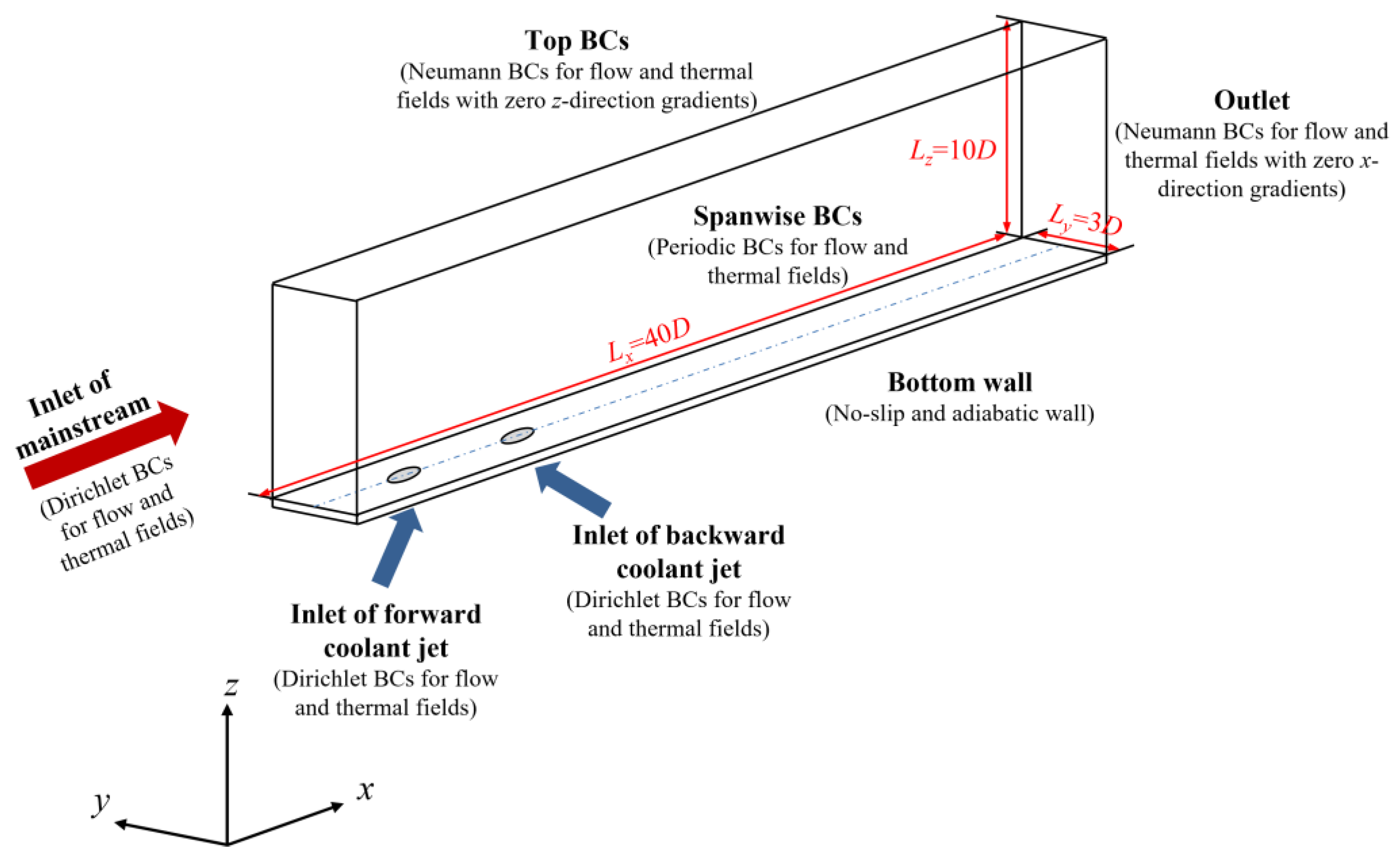
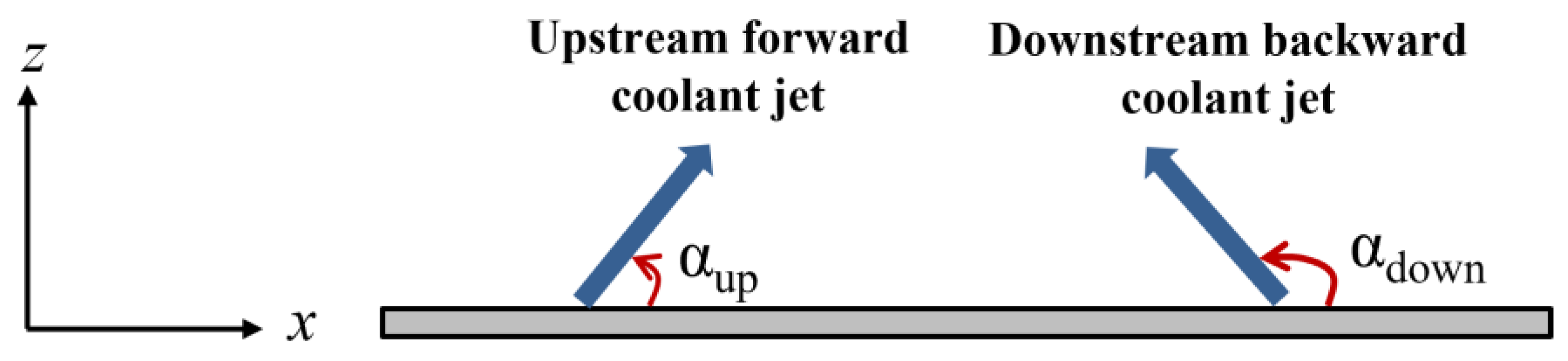
2. Computational Domain and Boundary Conditions

The computational domain for double-row film cooling with an upstream row of forward coolant jets and a downstream row of backward coolant jets is shown in Figure 1, which includes a mainstream channel with a size of L x × L y × L z = 40 D × 3 D × 10 D and two rows of film cooling holes with a hole diameter of D. L x , L y , and L z denote the length of the mainstream channel in streamwise, lateral and wall-normal direction, respectively. The upstream forward holes are located at the site that is 10D away from the mainstream inlet. The row-to-row space is 4D. The hot mainstream with a constant temperature of T flows over the bottom wall with a constant velocity u . A coolant jet with a constant temperature of T j is injected into the boundary layer of the mainstream via a film cooling hole and forms a coolant film to avoid direct contact of the bottom wall with hot mainstream. The Reynolds number based on the mainstream velocity u and the diameter of film cooling hole D is defined below:
R e = ρ u D ν
where ν is the molecular kinetic viscosity of mainstream.
The blowing ratio, one of the most important flow parameters for film cooling, can be expressed as
B R = ρ j u j ρ u
Here, ρ and ρ j represent the density of mainstream and coolant jet, respectively. u j is the coolant jet velocity. In the simulation of this present work, R e and BR are constant and respectively set as 1000 and 0.5. The ratio between the hot mainstream temperature T and coolant jet temperature T j is equal to T / T j = 2.0 . As for the inclination angle, its value for the upstream forward jet is α u p = 35 ° , while for the downstream backward jet, five values of α d o w n = 135 ° , 140 ° , 145 ° , 150 ° and 155 ° are taken into consideration. The definition of the inclination angle of the coolant jet is shown in Figure 2. The inclination angle of the coolant jet is the angle measured counterclockwise from the positive x-axis. This is why the inclination angle of the upstream jet with forward injection α u p is the acute angle, while the inclination angle of the downstream backward coolant jet α d o w n is the obtuse angle.
The setting of boundary conditions (BCs) in the computational domain is also indicated in Figure 1. For the inlets of the mainstream and coolant jets, the Dirichlet BCs are employed in both the flow and thermal fields. The outlet is set as Neumann BCs with zero gradients of flow and thermal properties in a streamwise (x-) direction. Periodic BCs are applied at the front and back sides of the mainstream channel in a lateral (y-) direction. Meanwhile, for the top side of the mainstream channel, both the flow and thermal properties are assumed to be fully developed in a wall-normal (z-) direction, leading to Neumann BCs with zero gradients in the z-direction. The bottom wall of the mainstream channel is assumed to be adiabatic and no-slip.

3. Governing Equations and Turbulence Model

In this work, STLBM is adopted to conduct the simulation of film cooling. STLBM is the extension of LBM, which directly updates the macroscopic variables without the achievement of the distribution-function evolution. This can greatly reduce the cost of virtual memory. Moreover, STLBM inherits all the advantages of LBM, such as simple computation, simple programming and easy implementation of the boundary condition. Therefore, STLBM demonstrates superiority in fulfilling large-scale simulations with limited hardware resources.

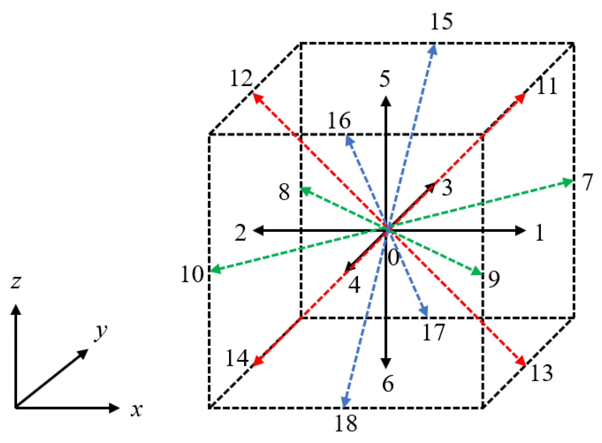
3.1. Simplified Thermal Lattice Boltzmann Method

For LBM, the density distribution f i and temperature distribution function g i are applied to show the development in the flow and thermal fields. The lattice Boltzmann equation (LBE) for f i and g i can be written as [32]:
f i ( x + e i Δ t , t + Δ t ) = f i ( x , t ) + 1 τ f f i e q x , t f i x , t
g i ( x + e i Δ t , t + Δ t ) = g i ( x , t ) + 1 τ g g i e q x , t g i x , t
Here, the discrete velocity e i of the particle at the position of x = ( x , y , z ) is applied to describe the evolution of the flow and thermal fields. Δ t is the time step adopted in the simulation. τ f and τ g denote the relaxation factors related to kinematic viscosity ν and thermal diffusivity α , respectively. f i e q and g i e q are the equilibrium distribution functions of density and temperature, respectively.
Since the continuity and momentum equations can be recovered from Equation (3), the energy equation is recovered from Equation (4) by assuming that the viscous dissipation and the compression are neglected; the macroscopic density ρ , velocity u and the fluid temperature T in the thermal lattice Boltzmann method (TLBM) are derived as [32]:
ρ x , t = i = 0 N 1 f i x , t u x , t , u x , t = 1 ρ i = 0 N 1 e i f i x , t , T x , t = i = 0 N 1 g i x , t
It is noted that all the density and temperature distribution functions should be stored in the collide and streaming steps of TLBM, resulting in great consumption of virtual memory. This brings much difficulty to the achievement of large-scale simulations. In STLBM, the whole calculation process is performed by the direct evolution of the macroscopic flow and thermodynamic quantity, avoiding the dependence on distribution functions. It results in less virtual memory and simpler boundary conditions implementation. Moreover, previous investigations [33,34] have indicated that STLBM is unconditionally stable. Compared with the conventional TLBM, STLBM has superiority in numerical stability, boundary treatment and memory cost.
In STLBM, the macroscopic physical parameters of the discrete particle, such as density ρ , velocity u and temperature T , can be predicted by the predictor step and corrector step, as shown below [35]:
Predictor step:
ρ * x , t = i f i e q x e i Δ t , t Δ t
ρ * x , t u * x , t = i e i f i e q x e i Δ t , t Δ t
T * x , t = i g i e q x e i Δ t , t Δ t
Corrector step:
ρ x , t = ρ * x , t
ρ x , t u x , t = ρ * x , t u * x , t + 1 1 τ f i e i f i n e q x e i Δ t , t + F E x , t Δ t
T x , t = T * x , t + 1 1 τ g i g i n e q x e i Δ t , t
In the above equations, the symbols with the superscript * are the intermediate values. f i n e q and g i n e q represent the non-equilibrium distribution functions of density and temperature, respectively. The approximation of f i n e q and g i n e q can be expressed as [35]:
f i n e q x , t = τ f f i e q x , t f i e q x e i Δ t , t Δ t
g i n e q x , t = τ g g i e q x , t g i e q x e i Δ t , t Δ t
Note that the prediction of f i e q and g i e q are fulfilled with the intermediate parameters ρ * , u * and T * obtained in the predictor step. In this work, for the three-dimensional simulation, the velocity set D3Q19 is adopted. Figure 3 illustrates the schematic representation of discrete velocity directions in the D3Q19 model. Correspondingly, the weighting factors of various discrete velocity directions are expressed in Equation (14) [32]. It is illustrated that the weighing factor of the 0-direction is 1/3. 0 represents that the particle is stationary. The weighing factor of the directions, which is parallel to the x-, y- and z-axes, is 1/18. The weighing factor of the directions, which is parallel to the diagonal of x-y plane, y-z plane and x-z plane, is set as 1/36.
ω i = 1 / 3 , i = 0 1 / 18 , i = 1 6 1 / 36 , i = 7 18
According to Ref. [32], the equilibrium distribution functions f i e q and g i e q of the D3Q19 discrete velocity model can be written as:
f i e q = ω i ρ 1 + e i · u c s 2 + e i · u 2 2 c s 4 u 2 2 c s 2
g i e q = ω i T 1 + e i · u c s 2 + e i · u 2 2 c s 4 u 2 2 c s 2
In the film cooling process, the external force term is the buoyance force, which is in connection with temperature according to the Boussinesq approximation [36]. The corresponding expression is shown below:
F E ( x , t ) = 0 ρ g β T ( x , t ) T 0 ( x , t )
In which g and β denote the gravitational acceleration and thermal expansion coefficient, respectively. T 0 represents the reference temperature, which is the temperature difference between the hot mainstream and coolant jet in this work.

3.2. Smagorinsky Subgrid-Scale Stress Model

The LES-SGS model, an explicit and validated model of LES, is adopted in this work for the simulation of turbulent flow and heat transfer. In the LES-SGS model, introduced to LBM by Hou et al. [37], the molecular viscosity ν 0 is replaced by effective viscosity ν e f f to take the comprehensive effect of molecular viscosity ν 0 and SGS eddy viscosity ν t into account. ν e f f can be calculated as follows:
ν e f f = ν 0 + ν t
The SGS eddy viscosity ν t is defined as:
ν t = C S Δ 2 2 α , β S ¯ α β S ¯ α β
Here, the size of the filter length scale Δ is equal to the grid size Δ x in STLBM. By following our previous work [38], the Smagorinsky constant is set as C S = 0.13 . The filtered strain rater tensor S ¯ α β can be deduced as:
S ¯ α β = 1 2 β u ¯ α + α u ¯ β
In this work, a two-order central difference scheme is chosen to compute the strain rater tensor.
Analogously, the effect thermal diffusivity α e f f can be deduced as follows:
α e f f = α 0 + α t
where α 0 and α t are the molecular thermal diffusivity and the turbulent thermal diffusivity, respectively. α t is in connection with the turbulent thermal Prandtl number, whose value is set as P r t = 0.87 [39] in this work.

3.3. Numerical Validation and Grid-Sensitivity Study

The STLBM-LES solver used in this work is improved based on the HTLBM code developed by the authors and accelerated by multiple graphic processing units (multi-GPUs). It should be emphasized that the HTLBM code was validated in our previous work [40] and good agreement was obtained. Furthermore, the computed results of the STLBM-LES code show good agreement with the experimental data of film cooling obtained by Chen et al. [41], which is presented in our recently published work [28].
In order to make sure all the numerical results obtained by the STLBM-LES solver are independent of the size of the computational grid, a grid-sensitivity study was also performed in our recently published work [28]. The film cooling effectiveness with B R = 0.5 , α u p = 35 ° , α d o w n = 145 ° was calculated with four grid systems whose total grid numbers, respectively, are 7.68 × 10 7 , 1.17 × 10 8 , 1.58 × 10 8 and 1.89 × 10 8 . The results show that the relative disparity becomes insignificant as the grid number exceeds 1.58 × 10 8 . Moreover, for the sake of meeting the best grid requirement of LES, 1.89 × 10 8 grids are adopted in all the simulations of this work to make the grid near the bottom wall satisfy z + < 1 . Further, the in-house STLBM-LES code is also accelerated by multi-GPUs. The simulations of this work are performed by applying two pieces of NVIDIA TeslaP100 GPUs, and a computational performance of 1089.5 MLPUS (Million Lattices Updated Per Second) is obtained.

4. Results and Discussion

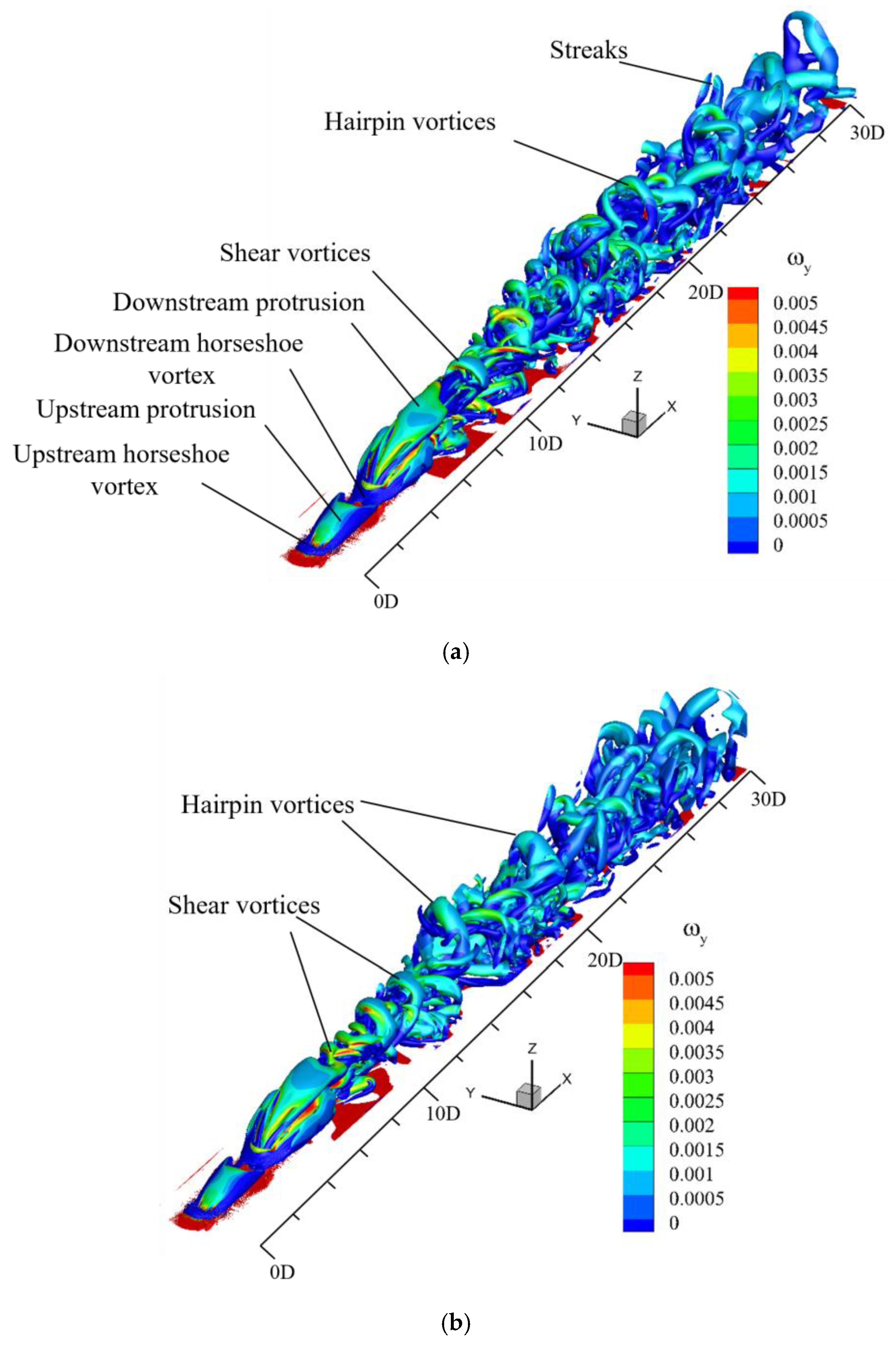
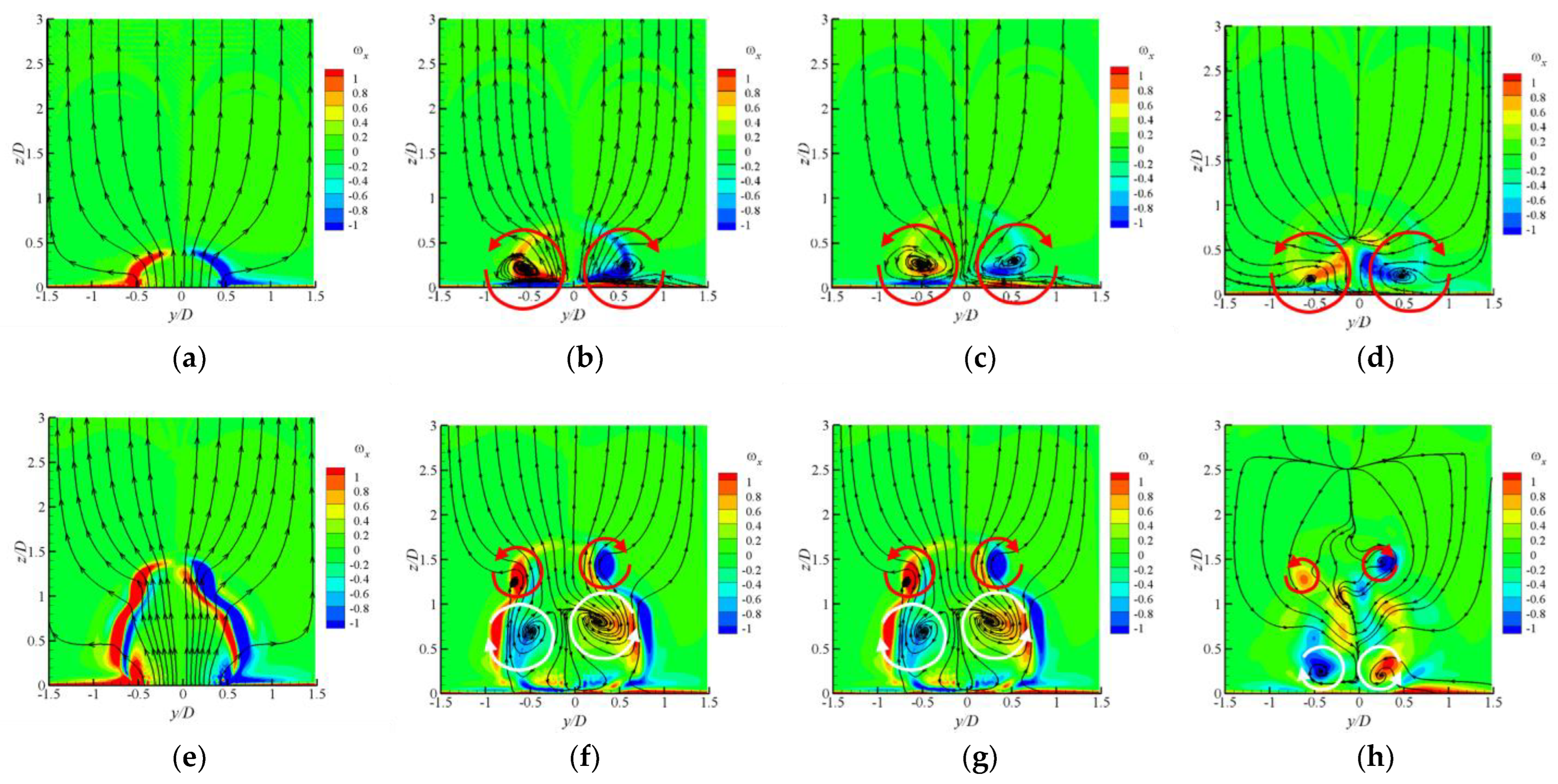
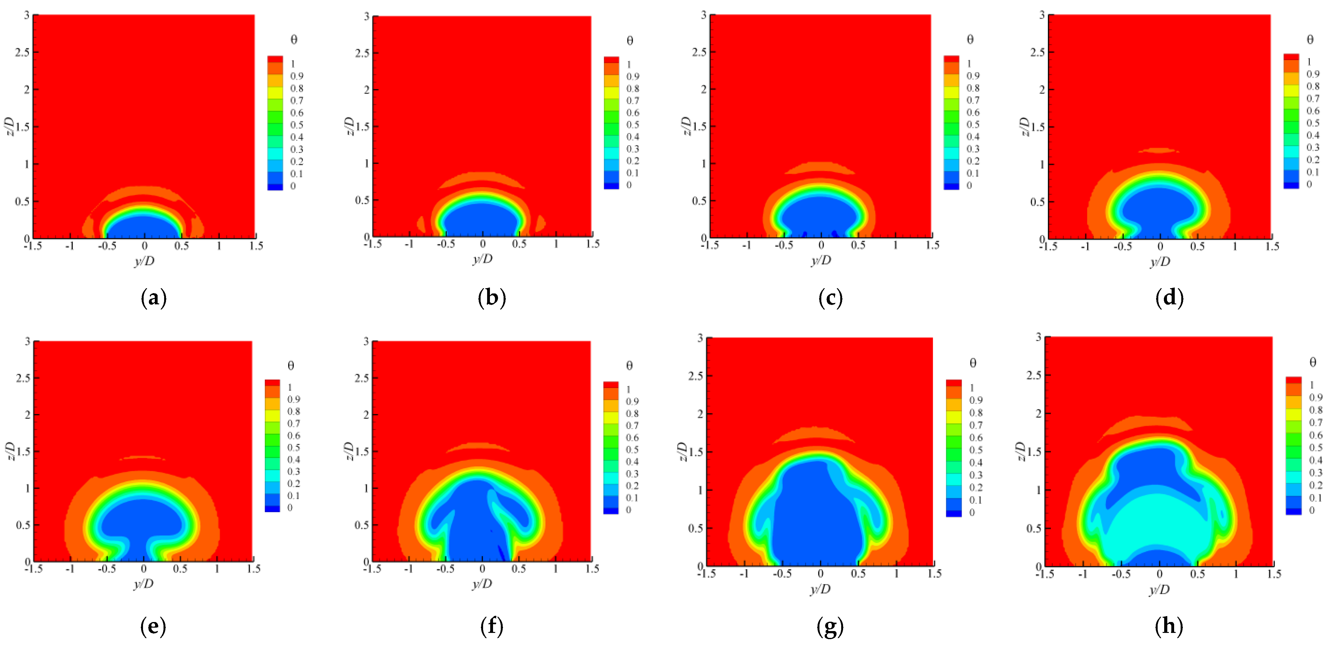
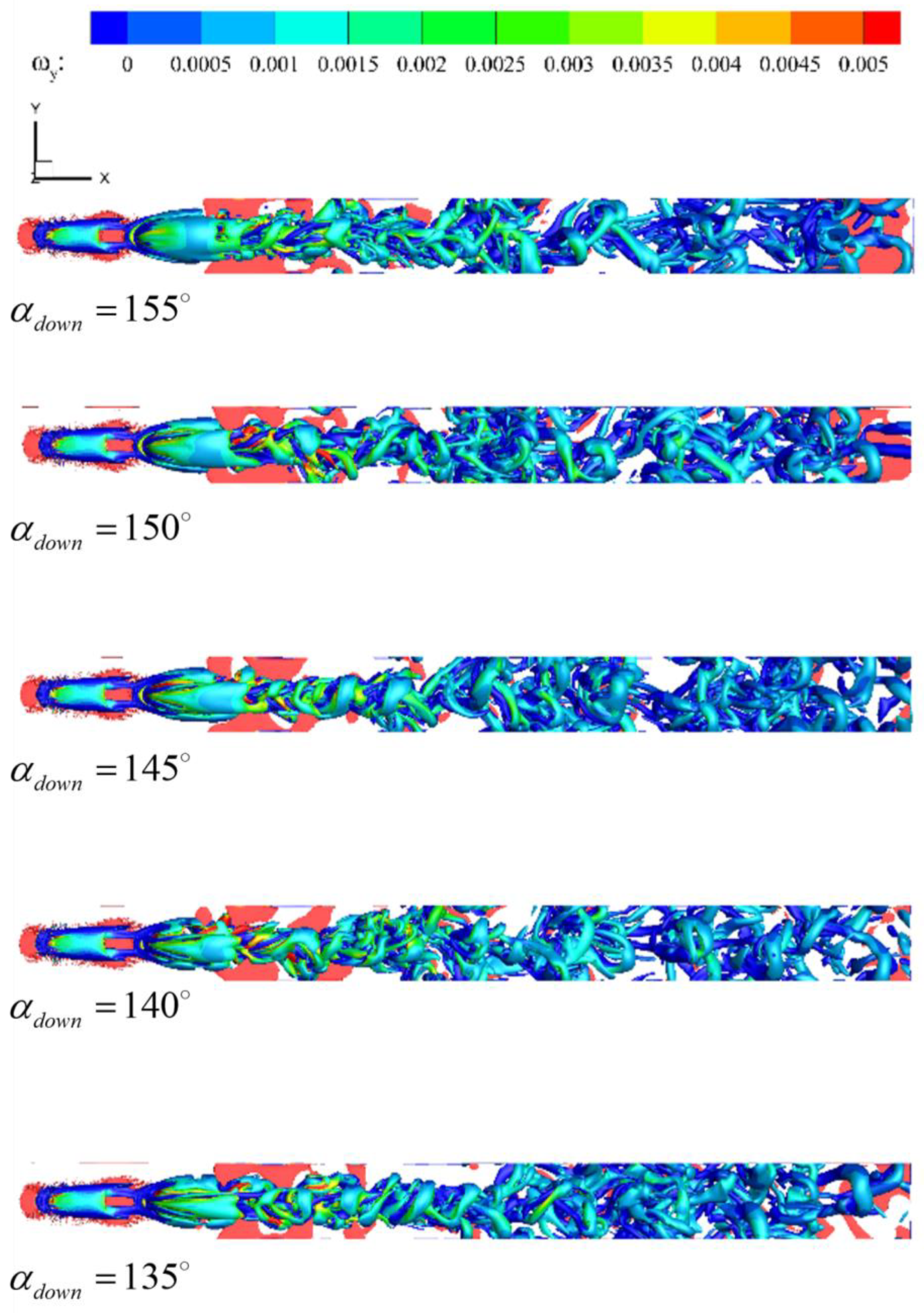
4.1. The Evolutions of Flow Structures

This part displays the details of the flow structures’ evolution, especially focusing on the flow structures in the region between rows. Here, the evolution time and length of all the flow structures are scaled by flow-through time t 0 and cooling hole diameter D . t 0 is the time that is taken by the mainstream to flow through the inlet of the mainstream to the outlet with the constant velocity u .
Figure 4 shows the instantaneous snapshots of coherent structures with B R = 0.5 , α u p = 35 ° , α d o w n = 145 ° at the instant of (a) t = 2.0 t 0 and (b) t = 6.0 t 0 , which indicate both the spatial and temporal evolution of flow structures in the whole flow field. In this paper, all the coherent structures are identified by the Q-criterion with an iso-surface of Q = 1.0 × 10 7 and colored by spanwise vorticity ω y = u / w w / x . It is found that the spatial evolution of flow structures along a streamwise (x-) direction is a typical process. A horseshoe vortex first appears at the leading edge of both the upstream and downstream film cooling holes. Subsequently, a protrusion forms above the film-cooling hole due to the strong blockage effect of the coolant jet. Just behind the downstream protrusion, the unstable corrugated-like shear vortices turn out. Hairpin vortices arise behind shear vortices. As the flow structures move downstream, the breakup of flow structures occurs, which is marked by large-scale distorted streaks. Moreover, the results of Figure 4a,b illustrate that the streamwise extension of shear vortices becomes larger, which changes from 1.0D to 5.0D as the instant time shifts from t = 2.0 t 0 to t = 6.0 t 0 . The hairpin vortices appear at about x = 20.0 D at the instant of t = 2.0 t 0 , while at t = 6.0 t 0 , the first appearance of hairpin vortices happens at x = 15.0 D . The interaction among vortices promotes the breakup of flow structures and enhances the turbulent mixing downstream. All of these lead to the violent momentum exchange of the mainstream and coolant jets at the expense of vorticity dissipation. Additionally, there are no visible flow structures except for the legs of the horseshoe vortex and protrusion shown in the region between upstream and downstream rows.
The details of the flow structures in the case of B R = 0.5 , α u p = 35 ° , α d o w n = 145 ° and B R = 0.5 , α u p = 35 ° , α d o w n = 35 ° are respectively shown in Figure 5a,b, to illustrate the effect of jet injection of the downstream row on the evolution of flow structures. Both the overhead and front views of flow structures are illustrated. The black dashed line shown in the front view represents the bottom wall. In the case of double-row film cooling with an upstream row of forward coolant jets and a downstream row of backward coolant jets, displayed in Figure 5a, the flow structures are hard to identify maybe because of the intensive mixing between mainstream and coolant jets. According to Figure 5a, the corrugated shear vortices just appear on the heels of the downstream protrusion ( x = 7.0 D ). These structures are unstable and a little distorted. Later, the hairpin vortices surrounded by streaks occur at the location of x = 15.0 D . The interaction among vortices has an important effect on the spatial evolution of flow structures. In the region of 15.0 D < x < 20.0 D , the interaction between hairpin vortices and the streaks leads to the breakup of flow structures at about x = 20.0 D . Many distorted streaks are illustrated in the downstream region of x = 20.0 D . The results of Figure 5b display that the flow structures in double-row film cooling with forward coolant jets are very compact and clear. Just in the rear of the downstream protrusion, a pair of hanging vortices form on the lateral sides. Then, a series of interlocking hairpin vortices appear around x = 11.0 D by linking with hanging vortices. Due to the lift-up motion introduced by hairpin vortices, the flow structures stay away from the bottom wall. Further, the shape of the downstream protrusion becomes different as the downstream jet changes from backward to forward injection. The sand dune-shaped downstream protrusion shows up in the case of B R = 0.5 , α u p = 35 ° , α d o w n = 145 ° (Figure 5a), while it changes into a pair of fly wings located at the lateral sides of the downstream film cooling hole in the case of B R = 0.5 , α u p = 35 ° , α d o w n = 35 ° (Figure 5b). All of these indicate that the injection of a downstream jet has a great impact on the spatial evolution of flow structures, especially in the region between rows.
Figure 6 illustrates the details of streamwise vorticity ω x and the streamlines under B R = 0.5 , α u p = 35 ° , α d o w n = 145 ° at various streamwise locations to study the effect of the interaction between the mainstream and jets on the lateral motion of vortices. The arrows on the streamlines represent the flow direction. Here, the region between rows obtains the special focus. It can be observed in Figure 6a–d that only a CVP, the typical vortex in film cooling with forward jets, forms near the streamwise location of x = 1.0 D (Figure 6b). The strength of the CVP becomes weaker and its wall-normal distance from the bottom wall becomes larger at x = 2.0 D (Figure 6c) and x = 3.0 D (Figure 6d). The motions of CVP, signaled with red curves with arrows, enhance the mixing between mainstream and upstream forward jets and lead the lift-up of the coolant jet. The results shown in Figure 6c,d also indicate that the injection of the downstream backward jet has little effect on the motions of streamwise vortices near the leading edge of the downstream hole. Additionally, the CVP disappears, replaced by a calabash-shaped vortex contour, as the downstream coolant jet is injected into the boundary layer of the mainstream at the point of x = 4.0 D (Figure 6e). Subsequently, a large anti-CVP occurs just above the bottom wall and below a small-sized CVP, nearby x = 5.0 D (Figure 6f). The motions of anti-CVP, whose rotation direction is opposite to that of CVP, are represented by the white curves with arrows. The downwash flow velocity caused by the anti-CVP leads to the attachment of the coolant jet to the surface of the bottom wall. Combined with the results shown in Figure 5, the authors believe that the mixing between the downstream backward jet and the mainstream results in the formation of anti-CVP, leading to an improved coolant-film coverage on the surface of the bottom wall. As the coolant jets flow downstream, the interaction between anti-CVP and CVP makes these vortices fade away gradually and induces the appearance of disordered small-scale vortices at the locations of x = 6.0 D (Figure 6g) and x = 7.0 D (Figure 6h). Large-scale structures dissipate into vortices with a small scale. The motion of the vortices with a small scale and their interaction are confused Moreover, the interaction among the small-scale vortices enhances the exchange of momentum and heat. The influence of vortices on the flow and heat transfer characteristics is analyzed further in the next subsection.

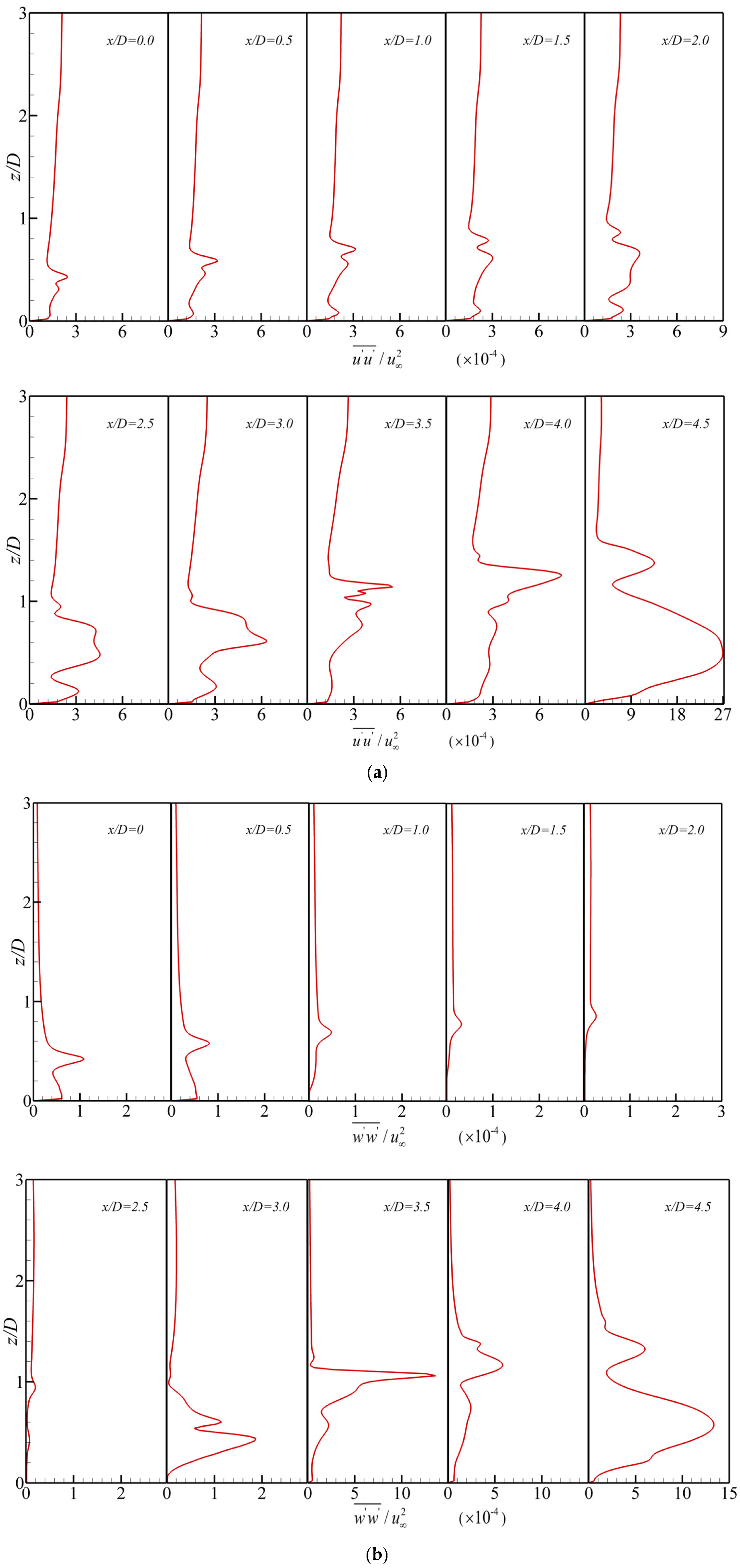
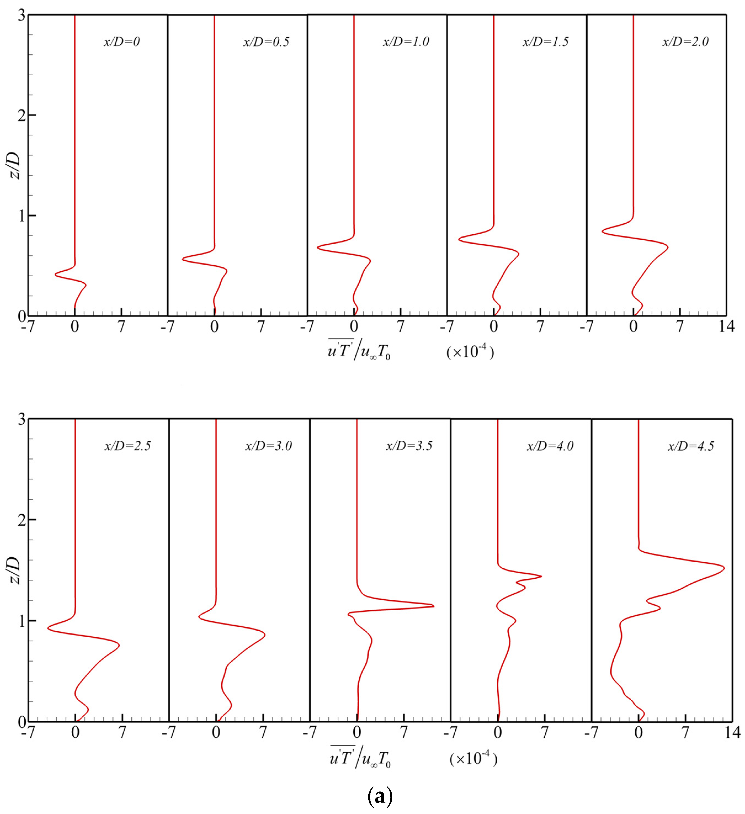
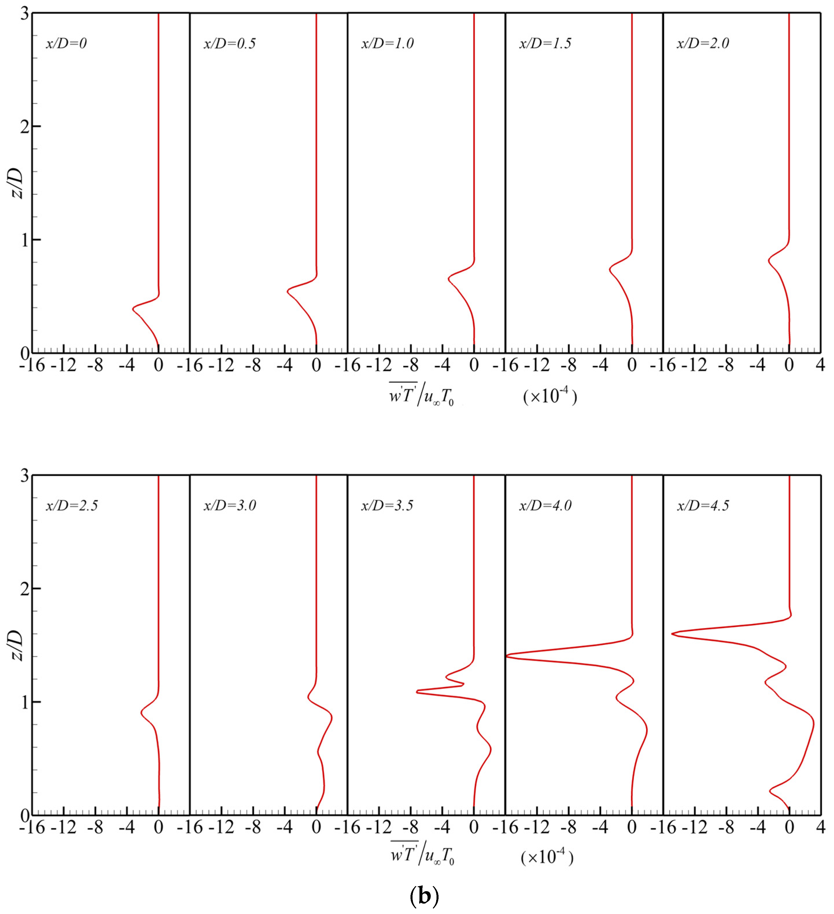
4.2. Momentum and Heat Flux Transport in the Region between Rows

The statistical parameters of turbulence are illustrated in this subsection to explore the effects of vortices on the flow and heat transfer characteristics of film cooling. Here, all the data are sampled at various streamwise (x-) locations in the region between rows. Since in this special region, the backward downstream coolant jet is just injected into the boundary layer of the mainstream, it is easy to examine both the mixing between the backward jet and the mainstream and the mixing between the backward and forward jets. The streamwise time-averaged velocity and streamwise fluctuation velocity under B R = 0.5 , α u p = 35 ° , α d o w n = 145 ° are exhibited in Figure 7a,b, respectively. All the curves describe the changes in flow variables along with the wall-normal distance from the bottom wall. The direction of the streamwise velocity component is the significant distinction between jets with forward and backward injections. Therefore, the flow variables in the streamwise direction are mainly focused on. The results illustrated in Figure 7a indicate that an obvious velocity gradient in the z-direction is observed near the bottom wall, which resulted from the strong viscous shear. Subsequently, there is a negative velocity gradient showing in the region ranging from z = 0.05 D to z = 0.6 D because of the mixing of the low-velocity coolant jet with the high-velocity mainstream. Then, as the wall-normal distance from the bottom wall increases, the value of streamwise velocity recovers to the initial value of mainstream. At the streamwise location of x = 3.5 D 4.5 D , a reduction of velocity gradient occurs in the near-wall region because of the injection of backward jet flow; meanwhile, the negative velocity gradient becomes less obvious. As for the streamwise fluctuation velocity (Figure 7b), there is also an obvious gradient near the wall; however, the gradient of the fluctuation velocity is negative. Because the coolant jet mixes with the mainstream, the gradient of fluctuation velocity reduces. Moreover, the injection of the backward jet weakens the velocity fluctuation near the bottom wall; however, it strengthens the fluctuation of velocity in the region far from the bottom wall ( z > 1.0 D ).
The Reynolds stresses in the streamwise direction R u u and in the wall-normal direction R w w under B R = 0.5 , α u p = 35 ° , α d o w n = 145 ° are illustrated respectively in Figure 8a,b. It can be observed that the jet injection has a marked impact on momentum exchange. The disturbance caused by the jet flow enhances both the streamwise and wall-normal momentum transport. Additionally, in the region near the downstream hole x = 3.5D–4.5D, the values of R u u and R w w increase sharply, implying that the backward jet flow intensifies the momentum transport more significantly. Moreover, because of the momentum exchange in the wall-normal direction, the core zones with a large value of Reynolds stress in streamwise and wall-normal directions stay away from the bottom wall, especially for wall-normal Reynolds stress R w w .
The non-dimensional temperature θ , defined as θ = T a w T j / T T j , is used to assess the heat transport. Here, T a w , T j and T represent the adiabatic bottom-wall temperature, coolant jet temperature and hot mainstream temperature, respectively. The non-dimensional temperature θ contours in the y-z plane at various streamwise locations between rows are illustrated in Figure 9. At the location of the center of the upstream hole ( x = 0 D ), shown in Figure 9a, the coolant-jet core attaches closely to the bottom wall and the shape of low-value temperature looks like an inverted ‘D’. Subsequently, a lifting of the coolant jet is generated by the entrainment of CVP, and a mushroom-shaped low-temperature contour arises between x = 1.0 D and x = 3.0 D (Figure 9c–e). In this region, the lateral coverage of coolant film becomes smaller. Then, at the point of x = 3.5 D (Figure 9f), the low-temperature contour with a mushroom shape is replaced by a rabbit-like temperature contour with larger lateral coverage, which is because of the backward jet injection. Following the mixing between mainstream and coolant jets with forward and backward injections, the rabbit-shaped coolant core splits into an inverted ‘D’ core and a hat-like core at the point of x = 4.5 D (Figure 9h), which implies that the downstream developments of the forward and backward coolant jets are totally different. As develops in the downstream region, the core of the forward jet detaches from the bottom wall due to the CVP’s entrainment, while the core of the backward jet attaches closely to the bottom wall because of the motion of anti-CVP, as illustrated in Figure 6. The downwash motion of anti-CVP enhances the coolant coverage in a lateral direction, improving the performance of film cooling.
To further examine the heat transport between rows, Figure 10a,b depicts, respectively, the heat flux in streamwise direction u T ¯ and in wall-normal direction w T ¯ under B R = 0.5 , α u p = 35 ° , α d o w n = 145 ° . The positive value of u T ¯ in Figure 10a indicates that the heat is transferred to a downstream region. The negative value of w T ¯ in Figure 10b implies that the heat is transported away from the bottom wall. As the backward jet is injected into the boundary layer of the mainstream, both the streamwise and wall-normal thermal transport becomes obvious. In the region between x = 3.5 D and x = 4.5 D , the values of u T ¯ and w T ¯ become negative near the wall. This phenomenon is especially noticeable at the point of x = 4.5 D . Although the injection of the backward jet strengthens the heat removal from the bottom wall, it prevents the coolant jet from developing downstream.

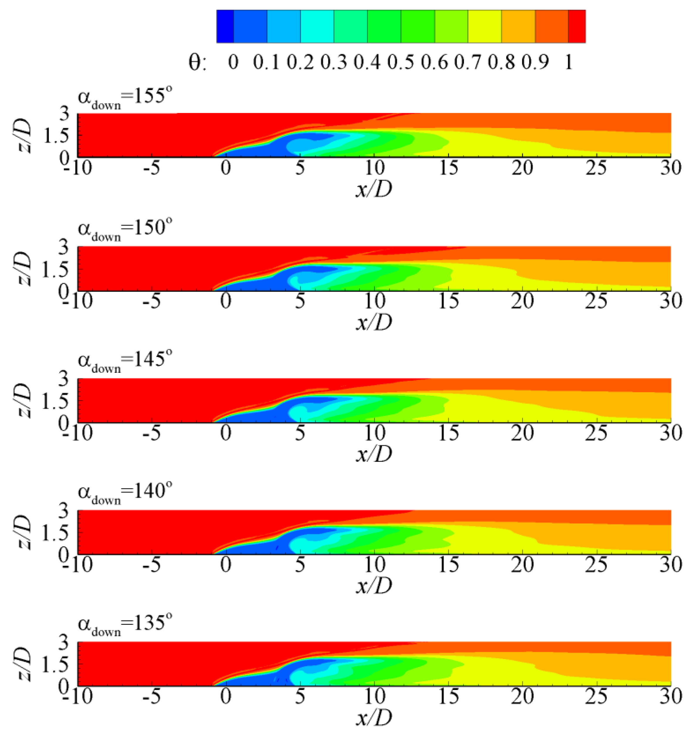
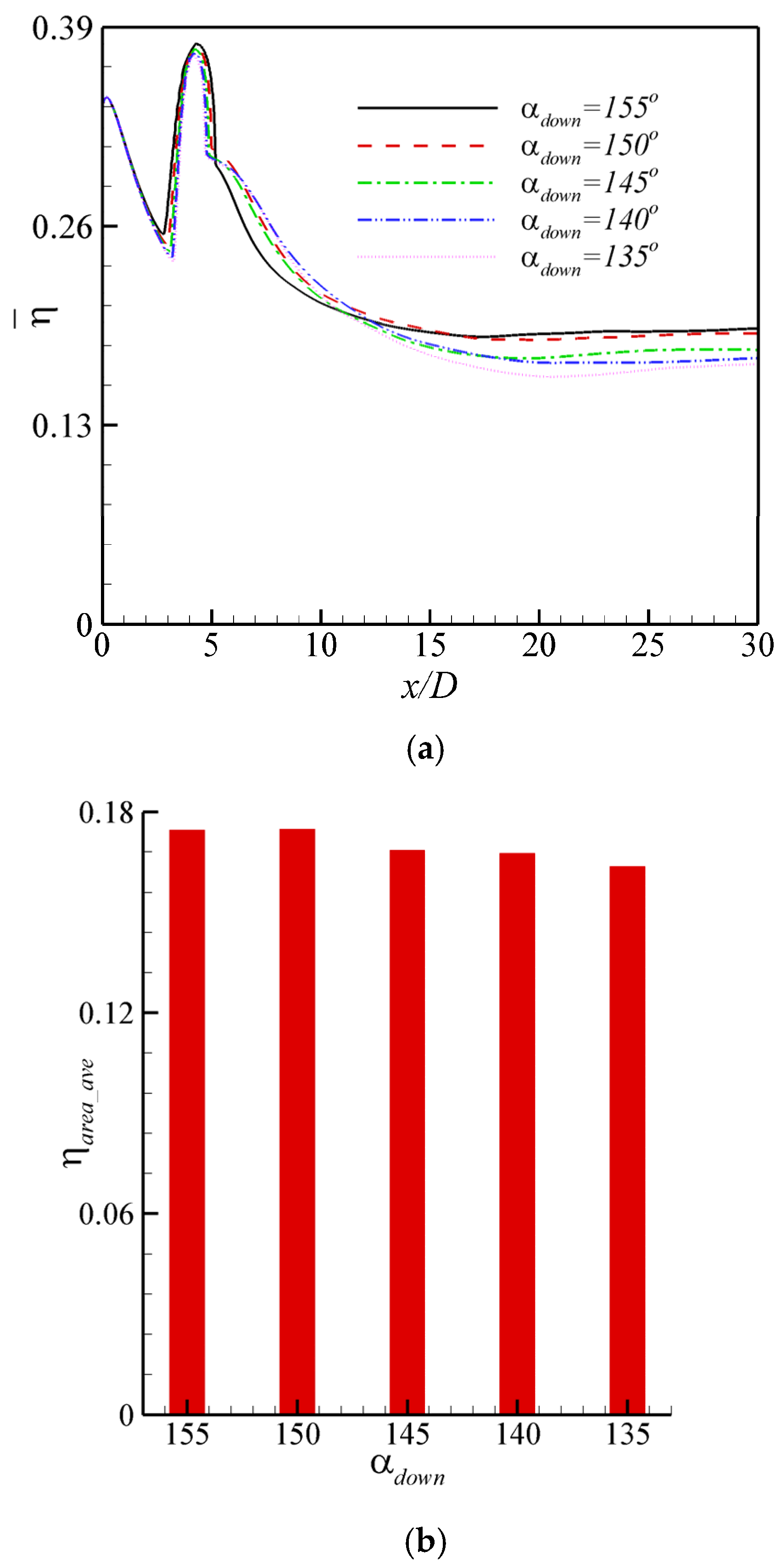
4.3. Effect of Injection Angle of Downstream Backward Jet

Figure 11 illustrates the overhead view of coherent structures to reveal the effect of the injection angle of the downstream backward jet on the evolution of flow structures. Here, the injection angle of the downstream backward jet ranges from α d o w n = 135 ° to α d o w n = 155 ° . As the value of α d o w n decreases, the protrusion near the downstream hole becomes more elongated because of the weakened blockage effect of the backward jet. Meanwhile, the streamwise extension of shear vortices enlarges and the evolution of flow structures becomes more unstable with the reduced inclination angle. The wall-normal momentum of jet flow is enhanced under the case with a small inclination angle of the downstream backward jet, leading to an intensified penetration of the coolant jet into the mainstream. The significant penetration of the jet results in the breaking up of flow structures and the generation of disordered streaks. As aforementioned, the interaction among streaks strengthens the momentum and heat transport, causing the instability of the coolant film.
To further analyze the influence of the inclination angle of the downstream backward jet on flow characteristics, Figure 12 displays the distributions of time-averaged spanwise vorticity ω y in the mid-span plane with various injection angles of the downstream backward jet. According to Figure 12, the obvious shear layer forms in the region between upstream and downstream rows (x = 0–5D) because of the strong shear effect between the mainstream and the jet. In addition, in the case of α d o w n = 155 ° , a significant backflow zone occurs just at the rear of the downstream hole. The strong backflow makes the coolant film attach closely to the bottom wall, enhancing the film-cooling performance. However, the backflow becomes weak and the lift-up of the coolant jet is obvious as the inclination angle of the downstream backward jet decreases.
Accordingly, the distributions of non-dimensional temperature θ in the mid-span plane with the inclination angle of the downstream backward jet ranging from α d o w n = 135 ° to α d o w n = 155 ° are depicted in Figure 13 to illustrate the effect of α d o w n on the covering of the coolant film. Although the streamwise extension of the coolant layer is enhanced by reducing the value of α d o w n , the adhesion of the coolant layer to the bottom wall becomes poor. This is mainly because the jet penetration into the mainstream is significant in the case of a small inclination angle of the downstream backward jet, causing the instability of the coolant layer and poor performance of film cooling.
Film cooling effectiveness η , given as η = T T a w / T T j , is utilized to quantitively exhibit the performance of film cooling. Figure 14 shows the comparisons of (a) the laterally averaged film cooling effectiveness η ¯ on the bottom wall and (b) area-averaged film cooling effectiveness η a r e a _ a v e with various inclination angles of the downstream backward jet α d o w n . As illustrated in Figure 14a, the value of η ¯ in the region between upstream and downstream rows (x = 0–5D) is improved under a large inclination angle of the downstream backward jet ( α d o w n = 155 ° ), while it is reduced sharply just behind the downstream hole, x = 5–12D. And then, a gentle reduction of η ¯ is shown in the downstream region ( x > 12 D ) mainly due to the interaction among streaks. In the other cases with smaller inclination angles of the backward jet, the jet with large wall-normal momentum penetrates violently into the mainstream, making the coolant film detach from the bottom wall, which lowers the value of η ¯ . It seems that the performance of film cooling with α d o w n = 155 ° is the best among the investigated cases of this study. This is fully demonstrated by the results of area-averaged film cooling effectiveness η a r e a _ a v e (Figure 14b). The value of η a r e a _ a v e generally decreases with a reducing inclination angle of the downstream backward jet α d o w n . Note that the value of η a r e a _ a v e is 0.1746 in the case of α d o w n = 155 ° , which is almost the same as that of α d o w n = 150 ° . The value of η a r e a _ a v e is 0.1749 under α d o w n = 150 ° . This special phenomenon may be concerned with the evolution of flow structures.
To further study the influence of α d o w n on the performance of film cooling, Figure 15 displays the laterally averaged value of the root mean square (RMS) of temperature T ¯ r m s on the bottom wall with various inclination angles of the downstream backward jet α d o w n . The large value of T ¯ r m s indicates the intensive fluctuations of the bottom wall’s temperature, which has an adverse impact on the performance of film cooling. Generally, the fluctuation of the bottom wall’s temperature becomes strong as the inclination angle of the downstream backward jet reduces. The value of T ¯ r m s with a large inclination angle of the downstream backward jet ( α d o w n = 155 ° ) remains small, except for the region just behind the downstream film cooling hole (x = 5D–8.5D), in which the strong backflow occurs. The results reflect that the fluctuation of the bottom wall temperature is weak in the case of a large inclination angle of the downstream backward jet ( α d o w n = 155 ° ).

5. Conclusions

In this present work, a verified in-house STLBM-GPU solver is utilized to investigate the spatiotemporal evolution of the flow structures and the coolant coverage in double-row film cooling with upstream forward jets and downstream backward jets. The effect of the inclination angle of the downstream backward jet is the focus. The main conclusions are drawn as follows.
The mixing between the downstream backward coolant jet and the mainstream leads to a special evolution of flow structures. A sand dune-shaped protrusion occurs above the downstream hole and large amounts of streaks turn out in the downstream region. The interaction among flow structures causes the generation of anti-CVP. The downwash motion of anti-CVP makes the core of the backward jet adhere closely to the bottom wall. However, the core of the forward jet keeps away from the bottom wall due to the CVP’s entrainment. Meanwhile, the downstream development of the jet with backward injection is less smooth than that of the forward jet.
The injection of the backward jet significantly influences the coolant coverage. The results indicate that the injection of the backward jet strengthens the heat removal from the bottom wall and prevents the coolant jet from developing downstream. In addition, the downwash motion of anti-CVP improves the coolant coverage in a lateral direction and enhances the stability of the coolant film. Therefore, the lateral coolant coverage is improved and the streamwise coolant coverage is reduced due to the injection of the backward jet.
The inclination angle of the downstream backward jet has a marked impact on flow and heat transfer characteristics. As the inclination angle of the downstream backward jet is small, the backflow happening in the trailing edge of the downstream hole is weak and the jet penetration into the mainstream is enhanced, which strengthens the instability of the coolant film. Hence, the film cooling effectiveness is decreased and the fluctuation of the bottom wall’s temperature is intensified under a small inclination angle of the downstream backward jet.

Author Contributions

Conceptualization, Y.S. and F.C.; methodology, Y.S.; software, Y.S.; validation, Y.S.; formal analysis, Y.S. and F.C.; investigation, Y.S.; resources, F.C.; data curation, Y.S.; writing—original draft preparation, Y.S.; writing—review and editing, Y.S. and F.C.; visualization, Y.S.; supervision, Y.S.; project administration, Y.S.; funding acquisition, Y.S. and F.C. All authors have read and agreed to the published version of the manuscript.

Funding

This research was funded by the Natural Science Foundation of Jiangsu Province, grant numbers BK20200182 and BK2020116; the Fellowship of China Postdoctoral Science Foundation, grant number 2020M671314; the Fundamental Research Funds for the Central Universities, grant number B230201020; and the Research on Smart Operation Control Technologies for Offshore Wind Farms, grant number 2019YFE0104800.

Data Availability Statement

Data is unavailable due to privacy restrictions.

Conflicts of Interest

The authors declare no conflicts of interest.

References

  1. Tan, Z.P.; Bibik, O.; Shcherbik, D.; Zinn, B.T.; Patel, N. The regimes of twin-fluid jet-in-crossflow at atmospheric and jet-engine operating conditions. Phys. Fluids 2018, 30, 025101. [Google Scholar] [CrossRef]
  2. Zhou, W.; Zhang, X.; He, C.; Wen, X.; Zhao, J.; Liu, Y. Simultaneous measurements of time-resolved velocity and concentration fields behind a sand dune-inspired jet in crossflow. Phys. Fluids 2021, 33, 115101. [Google Scholar] [CrossRef]
  3. Bogard, D.G.; Thole, K.A. Gas turbine film cooling. J. Propul. Power 2006, 22, 249–270. [Google Scholar] [CrossRef]
  4. Bunker, R.S. A review of shaped hole turbine film-cooling technology. J. Heat Transf. 2005, 127, 441–453. [Google Scholar] [CrossRef]
  5. Zhou, W.; Wang, K.C.; Yuan, T.J.; Wen, X.; Peng, D.; Liu, Y.Z. Spatiotemporal distributions of sweeping jet film cooling with a compact geometry. Phys. Fluids 2022, 34, 025113. [Google Scholar] [CrossRef]
  6. Kamotani, Y.; Greber, I. Experiments on a turbulent jet in a cross flow. AIAA J. 1972, 10, 1425–1429. [Google Scholar] [CrossRef]
  7. Walters, D.K.; Leylek, J.H. A detailed analysis of film-cooling physics: Part I-Streamwise injection with cylindrical holes. J. Turbomach. 2000, 122, 102–112. [Google Scholar] [CrossRef]
  8. McGovern, K.T.; Leylek, J.H. A detailed analysis of film cooling physics: Part II-Compound-angle injection with cylindrical holes. J. Turbomach. 2000, 122, 113–121. [Google Scholar] [CrossRef]
  9. Muldoon, F.; Acharya, S. DNS study of pulsed film cooling for enhanced cooling effectiveness. Int. J. Heat Mass Transf. 2009, 52, 3118–3127. [Google Scholar] [CrossRef]
  10. Sultan, Q.; Lalizel, G.; Fenot, M.; Dorignac, E. Influence of coolant jet pulsation on the convective film cooling of an adiabatic wall. J. Heat Trans. 2017, 139, 022201. [Google Scholar] [CrossRef]
  11. Ellis, C.D.; Xia, H. Impact of inflow turbulence on large-eddy simulation of film cooling flows. Int. J. Heat Mass Transf. 2022, 195, 123172. [Google Scholar] [CrossRef]
  12. An, B.T.; Liu, J.J.; Zhou, S.J. Effects of mainstream turbulence intensity and coolant-to-mainstream density ratio on film cooling effectiveness of multirow diffusion slot holes. J. Heat Transf. 2019, 141, 122001. [Google Scholar] [CrossRef]
  13. Yang, X.; Zhang, K.; Yao, J.; Wu, J.; Lei, J.; Su, P.; Fang, Y. Experimental and numerical investigation of vane endwall film cooling with different density ratios. Int. Commun. Heat Mass Transf. 2023, 144, 106778. [Google Scholar] [CrossRef]
  14. Cao, N.; Li, X.; Wu, Z.Y.; Luo, X. Effect of film hole geometry and blowing ratio on film cooling performance. Appl. Therm. Eng. 2020, 165, 114578. [Google Scholar] [CrossRef]
  15. Han, F.; Guo, H.; Ding, X.F.; Zhang, D.W.; Li, H.W. Experimental investigation on the effects of hole pitch and blowing ratio on the leading edge region film cooling of a rotating twist turbine blade. Int. J. Heat Mass Transf. 2020, 150, 119380. [Google Scholar] [CrossRef]
  16. Chen, D.; Du, Q.; Xu, Q.; Xu, G.; Liu, H. Film cooling and aerodynamic loss performance of turbine vanes with fan-shaped and wave -trenched holes. Appl. Therm. Eng. 2023, 230, 120643. [Google Scholar]
  17. Liu, C.L.; Ye, L.; Zhang, F.; Huang, R.; Li, B.R. Film cooling performance evaluation of the furcate hole with cross-flow coolant injection: A comparative study. Int. J. Heat Mass Transf. 2021, 164, 120457. [Google Scholar] [CrossRef]
  18. Zhou, W.; Hu, H. Improvements of film cooling effectiveness by using Barchan dune shaped ramps. Int. J. Heat Mass Transf. 2016, 103, 443–456. [Google Scholar] [CrossRef]
  19. Zhao, M.J.; Bian, Y.F.; Xu, J.J.; He, T.H. Large eddy simulation of film cooling with different upstream obstacles. Int. J. Therm. Sci. 2021, 161, 106722. [Google Scholar] [CrossRef]
  20. Subbuswamy, G.; Li, X.C.; Gharat, K. Numerical simulation of backward film cooling with fan-shaped holes. In Proceedings of the ASME 2013 Heat Transfer Summer Conference, HT2013-17801, Minneapolis, MN, USA, 14–19 July 2013. [Google Scholar]
  21. Subbuswamy, G.; Li, X.C.; Gharat, K. Numerical study of aerodynamic performance of film cooling with backward injection holes. In Proceedings of the ASME 2013 Heat Transfer Summer Conference, HT2013-17803, Minneapolis, MN, USA, 14–19 July 2013. [Google Scholar]
  22. Li, X.C. Numerical simulation on fluid flow and heat transfer of film cooling with backward injection. In Proceedings of the ASME International Heat Transfer Conference-2010, Washington, DC, USA, 8–13 August 2010; Volume 5, pp. 257–265. [Google Scholar]
  23. Park, S.; Jung, E.Y.; Kim, S.H.; Sohn, H.S.; Cho, H.H. Enhancement of film cooling effectiveness using backward injection holes. Int. J. Therm. Sci. 2016, 110, 314–324. [Google Scholar] [CrossRef]
  24. Singh, K.; Premachandran, B.; Ravi, M.R. Experimental and numerical studies on film cooling with reverse/backward coolant injection. Int. J. Therm. Sci. 2017, 111, 390–408. [Google Scholar] [CrossRef]
  25. Zhao, Z.C.; He, L.M.; Dai, S.J.; Shao, S. Computational research on film cooling performance of different shaped holes with backward and forward injection. AIP Adv. 2019, 9, 055009. [Google Scholar] [CrossRef]
  26. Chen, A.F.; Li, S.J.; Han, J.C. Film cooling with forward and backward injection for cylindrical and fan-shaped holes using PSP measurement technique. In Proceedings of the ASME Turbo Expo 2014, GT2014-26232, Dusseldorf, Germany, 16–20 June 2014. [Google Scholar]
  27. Singh, A.K.; Singh, K.; Singh, D.; Sahoo, M. Large eddy simulations for film cooling assessment of cylindrical and laidback fan-shaped holes with reverse injection. J. Therm. Sci. Eng. Appl. 2021, 13, 031027. [Google Scholar] [CrossRef]
  28. Shangguan, Y.Q.; Cao, F. An LBM-based investigation on the mixing mechanism of double rows film cooling with the combination of forward and backward jets. Energies 2022, 15, 4848. [Google Scholar] [CrossRef]
  29. Zhai, Y.N.; Liu, C.L.; He, Y.H.; Zhou, Z.X. Investigation on the film cooling performance of diffuser shaped holes with different inclination angles. Int. J. Turbo. Jet Engines 2017, 34, 123–139. [Google Scholar] [CrossRef]
  30. An, B.T.; Liu, J.J.; Zhou, S.J. Effects of inclination angle, orientation angle, and hole length on film cooling effectiveness of rectangular diffusion holes. J. Turbomach. 2018, 140, 071003. [Google Scholar] [CrossRef]
  31. Shangguan, Y.Q.; Wang, X.; Cao, F.; Zhu, Y.D. High resolution simulation of film cooling with blowing ratio and inclination angle effects based on hybrid thermal lattice Boltzmann method. Therm. Sci. 2022, 26, 3491–3503. [Google Scholar] [CrossRef]
  32. Chen, S.Y.; Doolen, G.D. Lattice Boltzmann method for fluid flows. Annu. Rev. Fluid Mech. 1998, 30, 329–364. [Google Scholar] [CrossRef]
  33. Chen, Z.; Shu, C.; Tan, D. Three-dimensional simplified and unconditionally stable lattice Boltzmann method for incompressible isothermal and thermal flows. Phys. Fluids 2017, 29, 053601. [Google Scholar] [CrossRef]
  34. Chen, Z.; Shu, C.; Yang, L.M.; Zhao, X.; Liu, N. Immersed boundary-simplified thermal lattice Boltzmann method for incompressible thermal flows. Phys. Fluids 2020, 32, 031605. [Google Scholar] [CrossRef]
  35. Chen, Z.; Shu, C.; Tan, D. A simplified thermal lattice Boltzmann method without evolution of distribution functions. Int. J. Heat Mass Transf. 2017, 105, 741–757. [Google Scholar] [CrossRef]
  36. Hirsch, G. Numerical Computation of Internal and External Flows; John Wiley: Hoboken, NJ, USA, 1988. [Google Scholar]
  37. Hou, S.; Sterling, J.; Chen, S.; Doolen, G.D. A lattice Boltzmann subgrid model for high Reynolds number flows. Fields Inst. Commun. 1994, 6, 151–168. [Google Scholar]
  38. Wang, X.; Shangguan, Y.Q.; Onodera, N.; Kobayashi, H.; Aoki, T. Direct numerical simulation and large eddy simulation on a turbulent wall-bounded flow using lattice Boltzmann method and multiple GPUs. Math. Probl. Eng. 2014, 2014, 742432. [Google Scholar] [CrossRef]
  39. Schlichting, H. Boundary-Layer Theory; Springer: Berlin, Germany, 2000. [Google Scholar]
  40. Shangguan, Y.Q.; Wang, X.; Li, Y.M. Investigation on the mixing mechanism of single-jet film cooling with various blowing ratios based on hybrid thermal lattice Boltzmann method. Int. J. Heat Mass Transf. 2016, 97, 880–890. [Google Scholar] [CrossRef]
  41. Chen, A.F.; Li, S.J.; Han, J.C. Film cooling for cylindrical and fan-shaped holes using pressure-sensitive paint measurement technique. J. Thermophys. Heat Transf. 2015, 29, 75–784. [Google Scholar] [CrossRef]
Figure 1. Sketch map of computational domain and BC settings.
Energies 17 03387 g001
Figure 2. Definition of inclination angle of coolant jet.
Energies 17 03387 g002
Figure 3. D3Q19 discrete velocity model.
Energies 17 03387 g003
Figure 4. Instantaneous snapshots of coherent structures with B R = 0.5 , α u p = 35 ° , α d o w n = 145 ° at the instant of (a) t = 2.0 t 0 and (b) t = 6.0 t 0 .
Energies 17 03387 g004
Figure 5. Details of the flow structures at the instant of t = 6.0 t 0 under (a) B R = 0.5 , α u p = 35 ° , α d o w n = 145 ° and (b) B R = 0.5 , α u p = 35 ° , α d o w n = 35 ° . (The dotted line shown in (b) represents the bottom wall).
Energies 17 03387 g005
Figure 6. The contours of time-averaged streamwise vorticity ω x under B R = 0.5 , α u p = 35 ° , α d o w n = 145 ° at the locations of (a) x = 0 D , (b) x = 1.0 D , (c) x = 2.0 D , (d) x = 3.0 D , (e) x = 4.0 D , (f) x = 5.0 D , (g) x = 6.0 D and (h) x = 7.0 D .
Energies 17 03387 g006
Figure 7. (a) The streamwise (x-) time-averaged velocity and (b) streamwise (x-) fluctuation velocity under B R = 0.5 , α u p = 35 ° , α d o w n = 145 ° .
Energies 17 03387 g007
Figure 8. (a) The streamwise Reynolds stress R u u and (b) the wall-normal Reynolds stress R w w under B R = 0.5 , α u p = 35 ° , α d o w n = 145 ° .
Energies 17 03387 g008
Figure 9. The contours of time-averaged non-dimensional temperature θ under B R = 0.5 , α u p = 35 ° , α d o w n = 145 ° at the locations of (a) x = 0 D , (b) x = 0.5 D , (c) x = 1.0 D , (d) x = 2.0 D , (e) x = 3.0 D , (f) x = 3.5 D , (g) x = 4.0 D and (h) x = 4.5 D .
Energies 17 03387 g009
Figure 10. (a) The streamwise heat flux u T ¯ and (b) the wall-normal heat flux w T ¯ under B R = 0.5 , α u p = 35 ° , α d o w n = 145 ° .
Energies 17 03387 g010aEnergies 17 03387 g010b
Figure 11. The overhead view of instantaneous coherent structures at the instant of t = 6.0 t 0 with various inclination angle of downstream backward jet α d o w n .
Energies 17 03387 g011
Figure 12. The distributions of time-averaged spanwise vorticity ω y in the mid-span plane with various inclination angles of downstream backward jet α d o w n .
Energies 17 03387 g012
Figure 13. The distributions of non-dimensional temperature θ in mid-span plane with various inclination angles of downstream backward jet α d o w n .
Energies 17 03387 g013
Figure 14. The comparisons of (a) the laterally averaged film cooling effectiveness η ¯ on the bottom wall and (b) area-averaged film cooling effectiveness η a r e a _ a v e with various inclination angles of downstream backward jet α d o w n .
Energies 17 03387 g014
Figure 15. The comparisons of root mean square (RMS) of temperature T ¯ r m s on the bottom wall with various inclination angles of downstream backward jet α d o w n .
Energies 17 03387 g015
Disclaimer/Publisher’s Note: The statements, opinions and data contained in all publications are solely those of the individual author(s) and contributor(s) and not of MDPI and/or the editor(s). MDPI and/or the editor(s) disclaim responsibility for any injury to people or property resulting from any ideas, methods, instructions or products referred to in the content.

