Review

A Review of Thermochemical Energy Storage Systems for District Heating in the UK

by
Sarah Roger-Lund
*,
Jo Darkwa
,
Mark Worall
,
John Calautit
and
Rabah Boukhanouf
Building, Energy and Environment Research Group, Faculty of Engineering, The University of Nottingham, Nottingham NG7 2RD, UK
*
Author to whom correspondence should be addressed.
Energies 2024, 17(14), 3389; https://doi.org/10.3390/en17143389
Submission received: 11 June 2024 / Revised: 27 June 2024 / Accepted: 28 June 2024 / Published: 10 July 2024

Abstract

:
Thermochemical energy storage (TCES) presents a promising method for energy storage due to its high storage density and capacity for long-term storage. A combination of TCES and district heating networks exhibits an appealing alternative to natural gas boilers, particularly through the utilisation of industrial waste heat to achieve the UK government’s target of Net Zero by 2050. The most pivotal aspects of TCES design are the selected materials, reactor configuration, and heat transfer efficiency. Among the array of potential reactors, the fluidised bed emerges as a novel solution due to its ability to bypass traditional design limitations; the fluidised nature of these reactors provides high heat transfer coefficients, improved mixing and uniformity, and greater fluid-particle contact. This research endeavours to assess the enhancement of thermochemical fluidised bed systems through material characterisation and development techniques, alongside the optimisation of heat transfer. The analysis underscores the appeal of calcium and magnesium hydroxides for TCES, particularly when providing a buffer between medium-grade waste heat supply and district heat demand. Enhancement techniques such as doping and nanomaterial/composite coating are also explored, which are found to improve agglomeration, flowability, and operating conditions of the hydroxide systems. Furthermore, the optimisation of heat transfer prompted an evaluation of heat exchanger configurations and heat transfer fluids. Helical coil heat exchangers are predominantly favoured over alternative configurations, while various heat transfer fluids are considered advantageous depending on TCES material selection. In particular, water and synthetic liquids are compared according to their thermal efficiencies and performances at elevated operating temperatures.

1. Introduction

Within the European Union, almost 80% of total domestic energy consumption is attributed to space heating and hot water, while space heating and industrial processes collectively represent over 70% of total industrial energy usage [1]. Longstanding fossil fuel dependence has traditionally sourced this usage, despite escalating concerns stemming from the climate crisis amidst expeditious population growth [2]. This has instigated a necessity to transition towards renewable energy technology, with sources such as wind and solar power having the potential to supply two-thirds of the global energy demand [3]. Nevertheless, the intermittent nature of renewable energy and its reliance on uncontrollable weather conditions remain central challenges. Addressing these challenges necessitates the integration of energy storage technologies with building decarbonisation techniques. This research aims to explore the potential of district heating systems when combined with fluidised bed thermochemical energy storage; such an approach is poised to offer substantial advancements in sustainable energy technology and climate resilience.
The International Energy Agency (IEA) has categorised industrial excess heat as either internally usable, externally usable, or non-usable within the process [4]. Non-usable industrial heat is therefore any excess heat that cannot be used internally or externally and is further defined as ‘waste heat’. Waste heat can be classified according to temperature as low-grade (<100 °C), medium-grade (100–400 °C), or high-grade (>400 °C) [5]. Low-grade is most abundant but also most difficult to recover, with effective recovery only possible in high quantities and with a ready use available. The total waste heat from UK industry and electricity generation is estimated to be almost 391,000 GWh per annum [6]; by EU averages, it is estimated that one-third of this is at temperatures below 200 °C [7]. Building decarbonisation is an integral facet of the UK government’s plan to achieve Net Zero carbon emissions by 2050, with low- and zero-carbon heating systems as a key focus for this progression. District heating (DH) utilises an external heat network to deliver heat to buildings as an alternative to internal heat generation through individual natural gas boilers. With regards to supply, DH systems can utilise heat from low- or zero-carbon sources, including waste heat from supplementary buildings or industrial processes. Indeed, modern networks operate at particularly low temperatures, with fourth-generation DH generally operating in the region of 60–80 °C [6], making them optimal for utilising low- and medium-grade waste heat. Utilising flows in this temperature range ensures that no material changes to building fabric are required. An example of far-reaching DH success has been established in Sweden, which has resulted in vast socioeconomic and environmental benefits such as the efficient use of local resources, low carbon dioxide emissions, and reliability of energy supply [8]. Despite DH systems becoming increasingly common in European countries such as Sweden, DH presently provides only 2% of the energy input for heating in the UK buildings sector. According to the Committee on Climate Change (CCC), this could be increased to 20% [9]. The key issues inhibiting widespread DH adoption are the time difference between energy generation and consumption, and the physical distance between generation plants and energy consumption locations [10]. This production and consumption discrepancy risks thermal energy being wasted. As such, energy storage has become an increasingly appealing solution due to its ability to manage the gap between demand and supply. Appropriate energy storage systems may expand both the flexibility and the performance of DH systems, further developing the smart integration of renewable energy sources with heat networks [10].
Thermal energy storage (TES) can be subdivided into three separate technologies, namely, sensible, latent, and thermochemical heat storage. Sensible heat storage is the most mature and established TES method in industry and uses a storage medium to directly store heat within the body [1]. Despite sensible heat storage materials generally being safe and inexpensive, a popular form being liquid water, they have lower energy densities than the materials used in both latent and thermochemical heat storage [11]. Of the former, energy is stored through a phase change at a fixed temperature, such as through melting, evaporation, or crystallisation. The stored energy is subsequently released upon the phase-change material (PCM) returning to its original state [12]. Conversely, thermochemical energy storage (TCES) utilises a reversible dissociation reaction where heat is stored during the endothermic reaction and is released during the exothermic reaction. The energy density that is available through TCES is a major point of interest, with volumetric density values averaging at 500 kWh/m3 reactant, a value five times that of typical PCMs [11]. Indeed, the chief advantage of TCES over other energy storage technologies is its unique capability to store energy with near-zero losses, making it potentially capable of inter-seasonal storage, and highly pertinent for variable heating demand applications such as district heating.
Implementing energy storage in a heat distribution system such as district heating may attain the following benefits [12]: better economics with reduced capital and operational costs; better efficiency regarding energy usage; reduced pollution and carbon dioxide emissions; and improved system performance and reliability. As such, the progression and application of this technology is growing increasingly relevant. However, for continual progression, there are obstacles to be overcome, namely, material development and reactor optimisation [13]. In existing research, the crucial issue with TCES in practice is its limited heat and mass transfer, which results in low system power outputs [14]. To optimise TCES materials with regard to energy density and stability, material development procedures such as nanomaterial coatings and doping can be utilised to ensure material characterisation. Further, reactor comparison between the relevant configurations of packed, moving, and fluidised beds gives rise to the assets of each, with particular regard for heat and mass transfer limitations. Enhancing the connection between a TCES reactor and district heating network via an efficient heat transfer system is also essential, with heat transfer fluid selection and heat exchanger design both being crucial factors to consider. This paper reviews each of these considerations in pursuit of the optimal configuration for a high energy-efficiency fluidised TCES system, aiming to sustainably decarbonise the UK buildings sector.

2. Literature Review

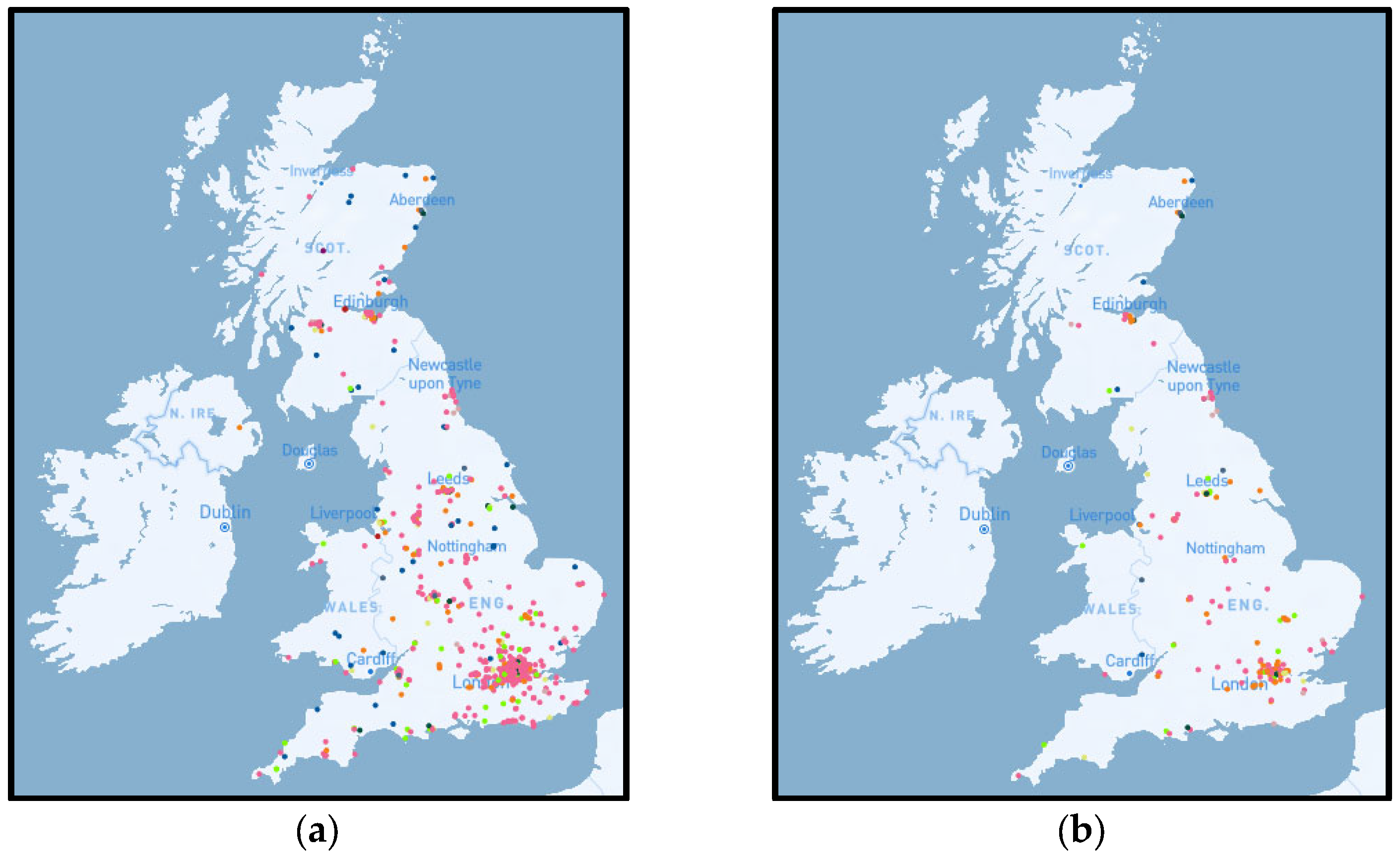
2.1. District Heating

In the UK, over half of all energy consumption is for thermal demand, 44% of which is accounted for by the domestic and industrial buildings sectors [15]. A fast-growing solution for combatting this demand is low-carbon district heating (DH), a technology which utilises heat from various energy sources and distributes it to consumers through a network of pipes. Energy sources include fossil fuels, renewable energy, and, most relevant to this research, local waste heat. The IEA defines waste heat as industrial heat that is usable neither internally nor externally in the process from which it is produced [4]. Waste heat can be classified according to temperature as low-grade (<100 °C), medium-grade (100–400 °C), or high-grade (>400 °C) [5]. Low- and medium-grade waste heat are most abundant, with their lower temperature values applicable for use in DH systems. Traditional DH systems use thermal energy from an appropriate source to heat water and produce steam, which is subsequently superheated. Such superheated steam may be used to generate electricity by turning a turbine but will primarily be passed through heat exchangers for conversion into pressurised hot water. For example, the Nottingham DH network uses energy from waste (EfW) to produce superheated steam at approximately 300 °C, which is transported at high pressure to a heat station, where it is cooled to hot water at 140 °C and 13 bar [16]. The pressurised hot water is then transported through the DH pipe network to domestic and commercial customers. From the heat station, it travels through a primary circuit which is linked to a secondary circuit via substations; here, the primary circuit water is mixed with the cooler return water from the secondary circuit to produce a flow temperature suitable for domestic heating. In the Nottingham case study, the 140 °C water from the primary circuit is mixed to produce a secondary flow of 88 °C, which heats the water for each household according to individual customer demand [16]. Throughout the network, pressure is regulated by constant and variable speed pumps. Pipes shorten in diameter as they move further away from substations, and valves are installed to absorb pressure fluctuations between adjoined pipes and houses. The Norwegian DH network is another case study, which delivered heat equivalent to 6672 GWh to homes, industry, and business in 2021, and has seen the amount of energy being delivered approximately doubling every ten years [17]. This system reflects expected thermal energy loss through distribution using pressurised water, which is approximately 10–12% [18].
Sweden is a particular case study for dramatic DH revolution; Figure 1 illustrates the historical substitution of fuel oil boilers with district heat, with DH market shares steadily increasing from 3% in 1960 to 57% in 2014 [9]. The fifty-year transformation of Sweden, from almost complete oil dependency to fuel oil accounting for 1% of all heat supply market shares, can be attributed to several institutional factors [19]. Namely, the strong Swedish municipalities and the regulations and policies in place. The Million Homes Programme was launched with the goal of building 1 million dwellings between 1965 and 1974, with local authorities coordinating the building of new residential areas alongside DH networks [20]. This initiative was further supported by The Heat Utility Association, which was later renamed the Swedish District Heating Association [19]. Upon its conception in 1949, the Association provided a forum for members to exchange information and discuss technical issues within the context of DH networks. Such incentives as these were instrumental factors in normalising and encouraging the implementation of DH networks in Sweden, with much of the primary market for DH covered by the 1990s and 2000s. This period was therefore focused on expanding existing networks into areas with lower heating density, and the building of small-scale DH systems. This was promoted by investment grants, with local authorities able to receive financial support for DH expansion between 1998 and 2002 from government-funded subsidy schemes such as Local Investment Programmes [19]. Correspondingly, a major energy tax reform in 1991 introduced a carbon tax, first set at 25 EUR/tonne CO2, which increased to 35.5 EUR/tonne CO2 in 1994, and further increased to 91 EUR/tonne CO2 in 2004 [19].
Presently, DH provides 2% of all energy input for heating in the UK buildings sector [10]. The UK government Department for Business, Energy, and Industrial Strategy published a Heat Networks Planning Database (HNPD) map which monitors the progress of both district and communal heat networks through the planning system across the UK [21]. Figure 2a presents this map with all 879 networks individually denoted by a suitably coloured dot depending on the energy type to source the network. Of these sources, air-source heat pumps are the most common with 557 projects represented, followed by gas-fired combined heat and power (CHP) and ground-source heat pumps at 146 and 56 projects, respectively. Excluding networks which have been either abandoned, application refused, or application withdrawn, causes the total number of networks to drop from 879 to 819. Nevertheless, the total number of applications submitted for new networks is reportedly 352, with a further 254 awaiting construction. Figure 2b therefore represents the total number of DH networks either finished and operational, undergoing pre-planning, or under construction, totalling 213 of the original 879 [21].
The CCC has estimated that 18% of UK heat will need to come from DH by 2050 for the UK to meet Net Zero cost-effectively [22]. Indeed, in a long-delayed consultation on low-carbon building standards, all fossil fuel heating systems including gas, hybrid heat pumps, and hydrogen-ready boilers have been ruled out for use in newbuild homes in England from 2025 [23]. This will increase the reliability of heat pumps and heat networks exponentially, not only improving energy efficiency and greenhouse gas emission levels, but also ensuring lower energy bills for occupants of newbuild homes. An example of DH development in the UK is the Nottingham network, which is the largest in the country with 68 km of insulated pipework, 5000 domestic homes, 100 commercial customers, and 27,000 tonnes of carbon dioxide emissions offset annually [16,24]. The DH network utilises thermal energy produced by Eastcroft Incinerator (EfW), which creates a supply of superheated high-pressure steam that is subsequently converted into high-pressure hot water, which is transported through a network of pipes. As the superheated steam is also used to generate electricity through a turbine, the Nottingham network supplies the equivalent of approximately 60,000 MWh of electricity per annum in addition to its supply of heating and hot water [16]. Nevertheless, the capital costs and disruption of installing a DH system are significant, with the Nottingham network requiring mass excavation to install underground pipes which run alongside the existing sewage and mains electricity systems [16]. Similarly to the Swedish Million Homes Programme, the north-Nottingham residential area of St Ann’s was demolished and rebuilt from scratch in the 1970s on top of the newly installed underground DH system. This is likely to be the necessary protocol for newbuild neighbourhoods in the UK to adhere to the fossil fuel heating system ban from 2025 [23]. Furthermore, despite 170,000 tonnes of waste per year being burned in the EfW plant, this is not enough to fully supply the network, with 40% of the total load being produced by supplementary coal-fired boilers [16]. Furthermore, the Eastcroft EfW system produces an abundance of waste heat which is currently deposited both into the atmosphere and into a nearby canal. A viable method for tackling the issues of energy supply shortage and energy waste is the adoption of energy storage. Not only can the merger of energy storage technologies with DH networks reduce the gap between energy production and consumption, but it can also encourage the incorporation of typically unreliable renewable energy sources.

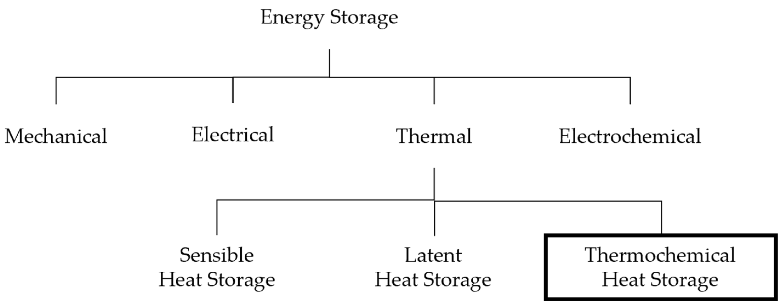
2.2. Energy Storage Technologies

Energy storage technologies can be broadly categorised according to the purpose for which the energy is stored: the four main groupings are mechanical, electrical, thermal, and electrochemical energy storage, as presented in Figure 3. Thermal energy storage is of particular interest to this research, so is further subcategorised into sensible, latent, and thermochemical energy storage. Despite all involving the three fundamental steps of heat charging, storage, and discharging, these mechanisms differ with regard to storage method, material availability, and industrial maturity [11]. Sensible and latent energy storage both increase the energy content of a material and store said material at an increased charging step temperature until discharge; the latter differs from the former as the energy storage increase initiates a phase change in the energy storage material, which is subsequently reversed during the discharging step. Thermochemical energy storage utilises a reversible dissociation reaction where heat is stored during the endothermic reaction and is later released during the exothermic reaction [11].
Storing heat via sensible energy storage provides advantageous characteristics of low cost and thermal stability. However, less favourable qualities such as the requirement of a larger volume, higher thermal loss, unstable discharge temperatures, and smaller energy storage densities are major disadvantages of a sensible heat system [25]. In comparison, latent heat storage materials generally have higher energy storage densities than that of sensible materials, and the technology is compact with a stable discharging temperature. Latent heat storage systems do however lack practical applications due to low thermal conductivity, poor thermophysical stability, the corrosive nature of phase-change materials (PCMs), phase segregation and subcooling, irregular melting, volume variation during phase transition, and higher costs [26]. Thermochemical energy storage (TCES) is considered highly energy efficient as it can yield the highest heat storage capacity of all TES options without producing any thermal losses during the storage period [27]. The efficiency of a material for thermal energy storage is primarily defined by its energy density; as TCES materials generally have much higher energy densities than their latent and sensible counterparts, they are considered much more efficient. Indeed, TCES materials average at 500 kWh/m3 reactant, in comparison to PCMs which average at 100 kWh/m3 reactant, and sensible heat materials at 50 kWh/m3 reactant [11]. These elevated energy density values make TCES capable of storing larger quantities of energy using smaller volumes of storage medium [28]. This comparison, in addition to other relevant parameters, is presented in Table 1 [11,25].
The development of TES-sourced DH systems is a means to improve existing networks by acting as a buffer between energy demand and supply. The merger of these systems allows to maximise both the flexibility and the performance of DH networks while incorporating renewable energy sources into thermal networks with a seamlessness that is otherwise seldom achieved [29]. TES systems can be characterised depending on duration as either short-term or long-term storage. With the former, the TES is used to supply the daily peak demand, with durations ranging from some hours to a day. Long-term TES allows for storage from several weeks to months; particularly, heat stored during summer months will be stored until winter months, when demand is higher. Presently, the majority of TES-DH systems utilise sensible technology consisting of vast water tanks, despite these having high space requirements, investment costs, and heat losses [30]. Sensible heat storage is highly dependent on land availability for installation, with short-term storage tanks usually requiring around 50–100 m2, and long-term storage requiring 10,000–100,000 m2. Moreover, short-term sensible heat storage averages thermal losses of 5%, and long-term 30% [31], and therefore requires significant insulation to extend their usability [32]. The advantages of TCES outlined above, in addition to the vast selection of materials available, make the technology appealing for DH systems. Indeed, the lack of thermal losses produced by TCES makes it a particularly appealing method for long-term storage solutions, or as a means of pairing energy demand with supply. The particular notoriety of TCES-DH networks is their ability to act as a ‘sink’ when surplus energy is available and as a source when extra thermal requirement occurs, thus seamlessly linking waste heat supply with DH demand [29]. Further, TCES can be used to ‘upgrade’ waste heat by increasing temperature, therefore improving efficiency in DH networks [32].

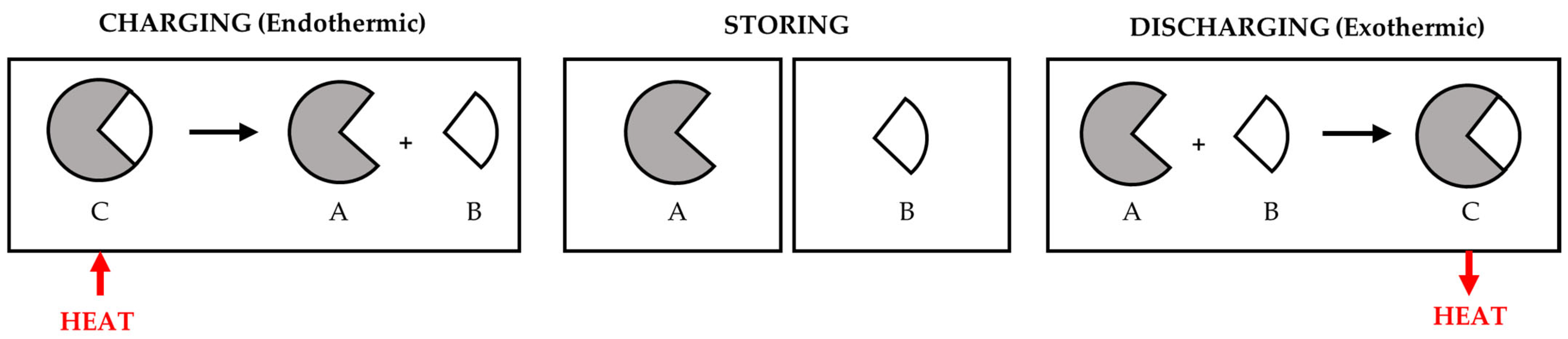
2.3. Thermochemical Energy Storage (TCES)

The discharging process of thermochemical energy storage (TCES) employs the exothermic pathway of the reversible reaction and is shown in Equation (1):
C + Δ H   A + B
Here, thermochemical material C absorbs energy ΔH to be chemically converted into separate components A and B. ΔH is therefore the enthalpy of the reaction. Components A and B can be stored separately (either at ambient or a working temperature), which in turn stores the energy absorbed by C to undergo its dissociation. Once A and B are combined again, C is reformed and the energy that had been stored is released once more; this released energy therefore comprises the recovered thermal energy from the system. Hence, the heat of the reaction when material C is formed is the storage capacity of the TCES system [28]. This process is further illustrated in Figure 4 [28].
The thermal energy stored Q (J) in thermochemical material C can be expressed as in Equation (2), where nC is the number of mols of C and ΔH is the reaction enthalpy (J/mol):
Q = n C Δ H
Thermal energy stored (Q) is in the form of chemical potential, equating to the energy per mole required to break up the chemical bond between components A and B. Utilising chemical reactions for thermal energy storage is particularly advantageous due to the theoretical capability for near-zero energy loss and resultant proficiencies for seasonal storage [11]. Further, TCES materials have very high energy densities, and heavy thermal insulation during TCES is unnecessary, unlike both sensible and latent storage [25]. Research suggests that the heat and mass transfer capability of TCES systems is the primary limiting factor with regard to this technology [33].

2.3.1. Material Selection

Identifying cost-effective and efficient TCES solutions necessitates a thorough analysis of appropriate storage materials and their qualities. For long-term (seasonal) heat storage, high-temperature reactions are required. While the amount of energy required by a DH network will differ due to usage variants, demands will generally range from about 5 GWh/annum for the base load of a rural grid, to about 100 GWh/annum for the base load of a large urban grid [30]. Hence, the key criterion when selecting TCES materials is a suitably high energy density. Specifically, energy densities should be greater than 0.60 MJ/kg, as values below this may require greater material quantities and therefore result in elevated operational expenses [30]. Other criteria to consider are keeping specific material costs low, availability greater than 200 tonne/month, and handleability and storage being uninhibited by the hazard categorisation of the material. Keeping specific material costs low is necessary to keep below the average costs for natural gas supply, and therefore remain competitive with existing DH networks. Furthermore, the nature of TCES systems, where thermal energy is stored through the separate storage of two reactants, gives a prerequisite to at least one of said reactants being a widely available resource [30]. Reactants such as oxygen (air) or water (liquid, steam, or saturated air) streamline storage requirements by necessitating storage for only one of the reactants, thereby minimising costs and complications associated with storage and resource handling. Previously researched reversible reactions are outlined in Table 2 and have been categorised by reactant family, energy density, and operating temperatures.
The advantages and disadvantages of each TCES system are summarised in Table 3 [11]. Advantages such as high energy density, reversibility, availability, and optimal operating conditions are considered more propitious than others. These have therefore been regarded more highly when comparing the TCES materials, in addition to more severe drawbacks being recognised such as incomplete conversion, the hazardous nature of materials, low thermal conductivity/heat and mass transfer, and the storage of materials that cannot be derived from air or water vapour. These considerations, in conjunction with the relevant energy densities and operating temperatures outlined in Table 3, allow for hydroxide systems to be concluded as the most appropriate for DH applications.

2.3.2. Hydroxide Systems

Two common hydroxide reactions applicable for TCES are magnesium and calcium hydroxide hydration/dehydration, with the general reaction scheme presented in Equation (3). Both systems are particularly advantageous due to their unique capability for the employment of water vapour, and the subsequent simplicity this brings to their utilisation.
M ( O H ) 2 ( s ) + H r M O ( s ) + H 2 O ( g )
Both CaO/Ca(OH)2 and CaO/CaCO3 systems are attractive for TCES due to their widespread availability, low cost, high safety, lack of side reactions, and particularly their high energy densities of 1.86 and 1.78 MJ/kg, respectively [44]. CaCO3 systems require higher temperatures (700–1000 °C) than their hydroxide counterparts (450–500 °C), making the Ca(OH)2 systems more appealing with regard to handleability and operational expenses. The reaction kinetics of CaO hydration and Ca(OH)2 dehydration are an integral factor when considering this TCES system. Although the reaction traditionally employs water vapour for the exothermic hydration of CaO, some research has been completed on the use of liquid water. Azpiazu et al. [45] carried out CaO hydration using water at 0 °C, monitoring specific heats, reaction rate and enthalpy, mass losses and heat release during hydration/dehydration cycles. Similarly, Irabien et al. [46] used deionised water at 25 °C to react with calcium oxide in a small-scale laboratory experiment to observe the solid–liquid reaction as opposed to the solid–gas reaction. It was found that the calcium oxide hydration has much higher energy storage efficiency when carried out with steam, with the enthalpy of reaction reducing from −104 to −62 kJ/mol for liquid water [38].
Both Schaube et al. [47] and Criado et al. [38] observed a decrease in hydration reaction rate with an increase in temperature when conducting kinetics analysis on the CaO/Ca(OH)2 system. Despite this, enhanced CaO hydration heat release demands high temperatures, thus entailing a requirement for elevated H2O partial pressures. Using H2O partial pressure of 1 atm gives a corresponding equilibrium temperature of 510–512 °C, with Schaube et al. monitoring reaction kinetics and cycling stability for H2O partial pressures up to 95.6 kPa [47]. It was found that a pure H2O atmosphere only allowed for 96% conversion after four hydration/dehydration cycles, although complete conversion was established with all other H2O partial pressures. Further, the cycling stability was unaffected with regards to conversion and rate for 100 hydration/dehydration cycles; this was confirmed by scanning electron microscopy (SEM) analysis, with minor refinement observed after 10 cycles but no further variation in the particles occurring between the 10th and 100th cycles. The same study conducted a kinetics analysis, concluding that the reaction rates for both the hydration and dehydration reactions are dependent on H2O partial pressure; two reaction pathways dependent on conversion were given for dehydration (Equations (4) and (5)), and two dependent on operating and equilibrium temperature difference were given for hydration (Equations (6) and (7)) [47]. Here, X is defined as conversion (mol/mol) and t is time (s), where the change in conversion over the change in time is taken to be the rate of reaction (1/s). R is the molar gas constant (J/mol K), T is the temperature (K), and P is the H2O partial pressure (Pa). The hydration kinetic equations display the vast discrepancy between the rate at lower temperatures, where the reaction proceeds within a few minutes, and at higher temperatures closer to equilibrium, when the reaction time is significantly prolonged [47].
Dehydration reaction rate for X < 0.2:
d X d t = 1.9425 × 10 12   e x p 187.88 × 10 3 R T · 1 P P e q 3 × 1 X
Dehydration reaction rate for X > 0.2:
d X d t = 8.9588 × 10 9   e x p 162.62 × 10 3 R T · 1 P P e q 3 × 2 1 X 0.5
Hydration reaction rate for TeqT ≥ 50 K:
d X d t = 13   945   e x p 89.486 × 10 3 R T · P P e q 1 0.83 ·   3 1 X × l n 1 X 0.666
Hydration reaction rate for TeqT < 50 K:
d X d t = 1.0004 × 10 34   e x p 53.332 × 10 3 T · P 10 5 6 × 1 X
Criado et al. [38] conducted a similar analysis, studying the CaO/Ca(OH)2 system at temperatures 400–560 °C and partial steam pressures 0–100 kPa using a thermogravimetric analyser (TGA). Both hydration and dehydration were found to be first-order reactions with respect to partial steam pressure, assuming spherical particles. Indeed, the inverse of the average particle diameter was found to correlate with reaction rate, thus indicating towards a ‘shrinking core model’, whereby the reaction progression causes the shrinking of solid particles. This was further proven by the detection of particle breakage, especially when utilising CaO particles of a larger diameter. Galwey et al. [48] conducted a fixed-bed laboratory study on the dehydration of 10 mg and 28 mg Ca(OH)2 samples using TGA. Findings indicated that the dehydration rates were influenced by the dispersion of reactant particles within the reaction tube in an ideal fixed bed. It was further concluded that the basic reaction was of first order. However, repeat hydration/dehydration cycles resulted in crystallite disintegration, which ensued an increase in the number of smaller particles, and consequently increased the rate of reaction in both directions [38,48]. Such key examples of particle breakage are indicative of the potential requirement for CaO-supported particles with better mechanical properties, especially for use in fluidised beds. Nonetheless, the Criado et al. [38] study also derived kinetics equations for CaO/Ca(OH)2 hydration/dehydration, which are displayed as Equations (8) and (9). Similarly to Schaube et al., these equations show the considerably slower reaction rate for hydration compared to that of dehydration.
Dehydration reaction rate:
d X d t = 5.2 × 10 2   e x p 60.8 × 10 3 R T · P e q P × 3 1 X 2 / 3
Hydration reaction rate:
d X d t = 2.5 × 10 6   e x p 59.4 × 10 3 R T · P P e q × 3 1 X 2 / 3
Magnesium oxide hydration has a smaller enthalpy of reaction than calcium oxide at −81 kJ/mol. With lower operating temperatures than the CaO/Ca(OH)2 system at 250–450 °C, the MgO/Mg(OH)2 system is arguably more appropriate for low-grade waste heat TCES-DH systems. However, MgO is inert to hydration in highly superheated steam, and the hydration reaction rate deteriorates with a rise in temperature [49]. Preliminary investigations indicate that the reaction rates in both directions are adequate for TCES applications; however, Ervin [37] ran a cycling study on MgO/Mg(OH)2 and observed an initial decrease in conversion from 95 to 60% before the fortieth cycle [11]. Despite this, the conversion retained stability for the remainder of the 500 cycles monitored. Kato et al. [50] used a thermobalance to monitor a Mg(OH)2 system for 100 cycles to gauge its suitability for use in a heat pump. A laboratory-scale heat pump with a reactor bed containing 1.8 kg reactant produced an output of up to 100 W/kg; however, the magnesium hydroxide did not prove to have adequate cyclability as its reactivity was reduced to 50% after the first ten cycles. Another study by Kato et al. [51] observed two different types of magnesium oxide material with a focus on improving the durability of the reaction cycle and subsequently increasing heat output performance. The materials tested were ultrafine magnesium oxide powder with an average diameter of 10 nm, and common magnesium hydroxide with an average diameter 5 µm. Using a thermobalance during repetitive reaction testing showed that the ultrafine MgO conversion decreased during the first five repetitions but remained constant at 50% from the 6th to the 24th cycle. Contrarily, common Mg(OH)2 decreased from an initial conversion of 60% to 20% in the 24th cycle. This suggests the higher durability and accompanying heat output of the ultrafine particles. The same study utilised transmission electron microscopy (TEM) to observe the morphology of the materials prior to and following the cycling analysis [51]. The hydrated ultrafine MgO particles were crystallised into simple hexagonal forms with diameters between 100 and 300 nm preceding cycling. Once 24 cycles had been achieved, the hexagonal forms had been generally lost, but a clear dispersion and similar particle diameters had been maintained. This is indicative that neither sintering nor particle size reduction took place during the hydration/dehydration repetition process. Conversely, the common Mg(OH)2 sample initially had no crystal form and a diameter distribution of 50–1000 nm, with the particle dispersion altering and particles smaller than 300 nm diameter being eliminated after 24 cycles. This suggests particle agglomeration during cycling, indicating the higher durability and resultant advantage of using ultrafine MgO particles. Indeed, Filippou et al. [52] observed the formation of relatively large Mg(OH)2 aggregates upon faster hydration of MgO. Such aggregates consisted of sub-microscopic crystallites with high surface area, making such particles less appealing for TCES applications.
The heat supply of the MgO/Mg(OH)2 system is greatly influenced by MgO properties, particularly dehydration temperature. With regards to kinetics, Pan and Zhao [53] measured the equilibrium hydration fractions of MgO prepared at various dehydration temperatures, allowing for the relationship between these variables to be established. The same was achieved for the reverse, with equilibrium hydration fractions of MgO at various hydration temperatures and pressures being determined. Results showed a significant reduction in dehydration reaction speed at lower temperatures, with 310 °C taking almost 400 min to reach 90% conversion, and 390 °C reaching 90% conversion after approximately 40 min. The conclusion drawn from these results was that the lower limit for the dehydration temperature should therefore be approximately 350 °C [53]. An upper limit was established through observing a decrease in the total heat output as the dehydration temperature increased from 400 to 700 °C. It was determined that to maintain satisfactory performance during TCES, the dehydration temperature must be retained below 500 °C. Yan et al. [54] describe the hydration process as the intermediate product MgO·H2O being formed by a rapid adsorption reaction, followed by Mg(OH)2 being generated slowly. Hence, the reaction temperature for hydration is limited by the evaporation temperature of the vapour, and is optimal at approximately 110 °C. These low temperatures make the MgO/Mg(OH)2 system particularly viable for medium-temperature applications, including both waste heat recovery and district heating. Pan and Zhao [53] established that both dehydration and hydration engendered particle aggregation and fracturing. The persistent cracking throughout the cycling ensured the continual provision of a fresh reaction surface for each hydration reaction, thus upholding a heightened reactivity. However, there was a counteraction to this cracking-induced reactivity enhancement, as the new reaction surface area was greatly reduced by concurrent particle aggregation. It was further concluded that the aggregation of MgO was increased with elevated temperatures. This is in accordance with a reduced reactivity being observed at higher dehydration temperatures. The findings allowed for dehydration kinetic equations for MgO/Mg(OH)2 to be derived, presented as Equation (10). Kato et al. [55] give a hydration kinetic equation, which is given as Equation (11).
Dehydration reaction rate:
d X d t = 1.51 × 10 8   e x p 1.33422 × 10 5 R T × 1 X 2 / 3
Hydration reaction rate:
d X d t = 5.85 × 10 20   e x p 8.34 × 4 R T × P v × ( X e q X )

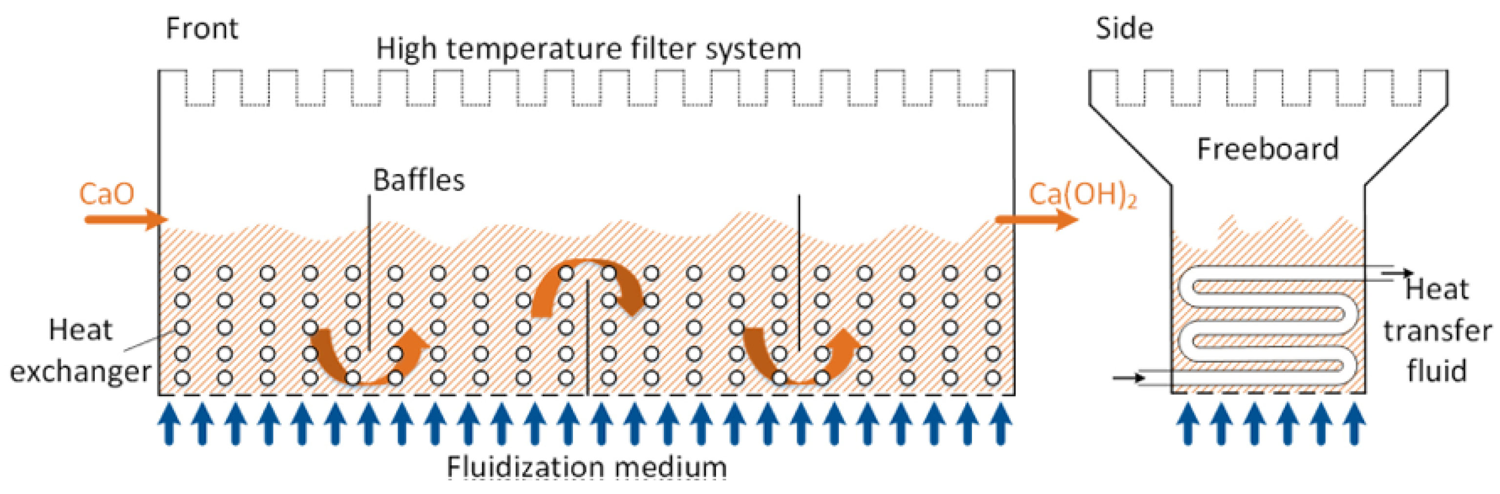
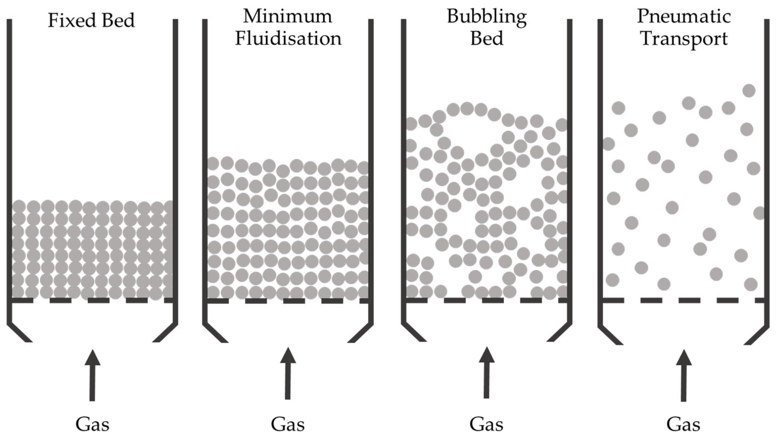
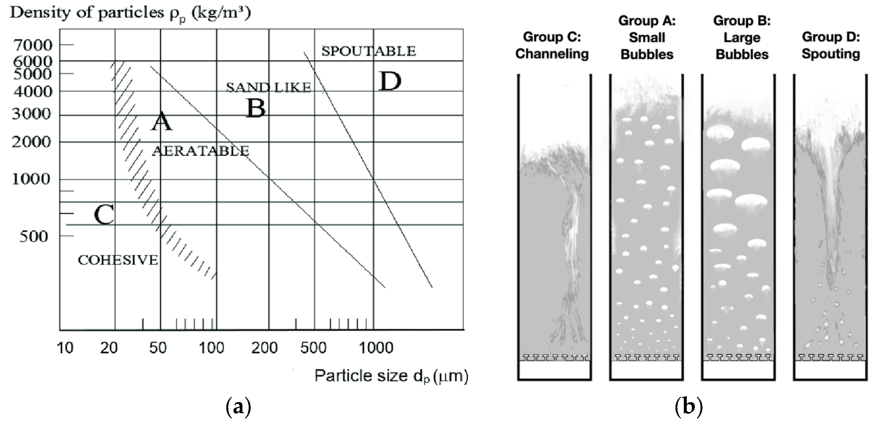
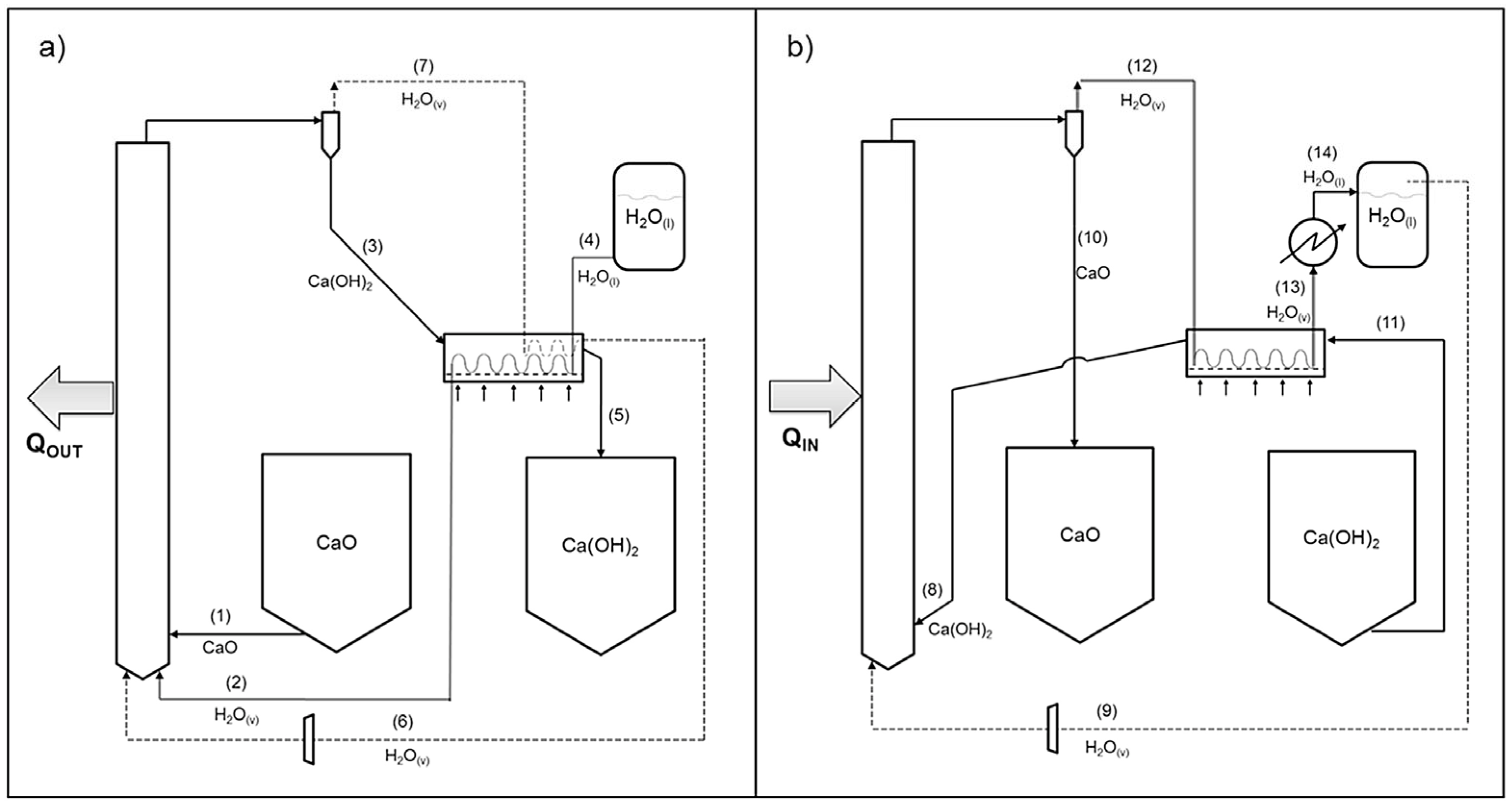
2.4. Thermochemical Reactors

Within the domain of thermochemical energy storage (TCES) systems, packed (fixed) beds remain the reactors most associated with the facilitation of hydration/dehydration cycling. Packed beds are filled with solid particles, which remain stagnant throughout the reaction process; fluid will generally flow vertically upwards through the packed bed of solid particles in order to react. It is common for reaction properties to be altered by the shape of the solid particles in the packing. For example, rings may be used to increase surface area, therefore increasing the rate of reaction. The association between TCES and fixed-bed reactors is largely due to the ease of production and operation that they provide [56]. Despite this, fixed-bed reactors are inherently limited with regard to heat and mass transfer due to their stationary nature [38]. Such limitations necessitate large (and costly) heat transfer surfaces for adequate thermal power ranges from the hydration/dehydration reactions required in large-scale TCES systems [57]. Further, increasing the reaction rate, and subsequently, the particle–fluid contact, demands high pressure drops within the storage vessel. It is possible to counteract this necessity by increasing the diameter of the solid particles in the vessel, although this dramatically reduces reaction kinetics and may incur particle breakage on account of resultant high stresses [38]. The other major disadvantage of fixed-bed reactors is the need for discontinuous (batch) operation, and thus the requirement for large heat exchangers for large storage capacities [40]. Batch operation is also regarded as unsuitable for TCES-DH integration.
An alternative for tackling such issues is the utilisation of a moving bed. These reactors operate similarly to fixed beds but incorporate an element of movement that allows for continuous operation, improved heat capacity, and fluid–particle interaction, and resultant heat and mass transfer [40]. Such movement is usually in the form of simply allowing particles to ‘flow’ down through a reactor while reacting fluid moves up, allowing for spent particles to be replaced throughout the operation. This is a well-practised process, although its key disadvantage is the influence of the shear and/or bubble formation in the reaction chamber, which can negatively influence heat and mass transfer [58]. Not only does this reduce the efficiency of the operation, but it is also costly with regard to the wear and subsequent replacement of solid particles. Further, unfavourable properties are the tendency of moving bed reactors to cause agglomeration and result in a poor ability to flow, especially when using finer particles. This is particularly disadvantageous for use with the relevant materials in this research, calcium and magnesium hydroxides, where the former has a particular tendency for agglomeration [59] and the latter is proven to have improved reactivity with the use of ultrafine particles [51]. Hence, an alternative method of interest is the use of fluidisation within the reactor bed. Such ‘fluidised bed’ reactors enable very high heat transfer coefficients, resulting in considerably reduced heat transfer area requirements.
Fluidised bed reactors, specifically for gas–solid fluidisation, pass a gas with increasing superficial velocity through a bed of powder, resulting in a linear drop in pressure until a maximum is reached [32]. At this maximum pressure, the gas velocity is deemed the minimum fluidisation velocity (MFV), meaning that the upward drag on the solid particles sufficiently counteracts their weight. This forms an emulsion of gas and solid particles which is said to be ‘fluidised’, causing the solid phase to dilate and behave as a fluid-like material. Fluidisation behaviour varies drastically for different materials and depends on the balance of drag, gravity, and particle–particle cohesive forces [32]. The fluidisation process is presented in Figure 5, where an increased gas inlet flow rate allows for the gradual fluidisation of the bed. MFV causes minimum fluidisation, and a further increase in gas velocity can result in the formation of bubbles which promote the mixing of the solid phase. The fluidisation process allows for high fluid-to-particle contact areas, which not only significantly improves heat and mass transfer but also increases the storage capacity of the TCES system [38].
Fluidised beds utilise incoming heat to force a thermochemical reversible reaction in the endothermic direction; in the example of calcium hydroxide, the endothermic direction is the dehydration of Ca(OH)2 into CaO and the resultant production of steam. As such, the heated air used to drive this reaction works as the fluidising gas in the reactor. The reverse works on the same principles, with the exothermic reaction between the fluidising steam/saturated air and the fluidised solid CaO particles resulting in thermal energy being released and Ca(OH)2 being reformed. Experimental results show that improved fluidisation uniformity in the reactor serves to enhance the reaction system by increasing fluid–particle contact areas, resulting in high mass transfer coefficients between the solid and gas [60]. Other advantages of fluidised bed reactors include [61] forward and backwards reactions occurring in the same reactor, homogenous temperatures, and well-known industrial scale-ups. Nonetheless, significant drawbacks include the need for a fluidisation gas, particle attrition, the potential requirement for a separation unit, and this technology being more expensive than both fixed and moving bed reactors. Fluidised beds can either be bubbling or circulating [32]. Bubbling fluidised beds (BFB) are more traditional, using a fixed chamber of particles and therefore being defined as a batch process. Circulating fluidised beds (CFB) enable continuous operation as they circulate the solid particles in and out of the bed without a recognised freeboard area. BFBs are less complex than their counterparts but are more suited to small-scale storage, with CFPs offering better mixing and thermal throughput at 5000–7000 kW/m2 compared to 1200–1600 kW/m2 for BFBs [62]. However, significant drawbacks of CFPs include the resultant cost of their complexity in addition to particle attrition and abrasion.
Geldart [63] gives four classifications for materials undergoing fluidisation which are presented in Figure 6a [64]. Group A is defined by particle diameters less than 40 µm and densities less than 1400 kg/m3; group B has particle diameters 40–500 µm, and particle densities 1400–4000 kg/m3. Group C is specifically for particles which are in any way cohesive and are generally very fine, and group D consists of particles so heavy or large that they are dominated by gravity and will not sustain bubbling. These groupings all behave differently, with the fluidisation behaviour of each group presented in Figure 6b [65]. The primary discrepancies between groups A and B are how quickly the beds will expand upon gas input, the bubbling size within the bed, and the settlement time upon the closing of gas supply. A bed of group D particles circulates through spouting, which causes particles to be driven upwards by a high-speed channel and accumulate at the reactor walls [32]. Materials in group C differ entirely due to interparticle forces generally being greater than those exerted on the particles by the fluid. The powder will lift as a plug or channel badly, often breaking large parts of the bed without forming a homogeneous mixture, thus preventing adequate fluidisation. This results in poor heat transfer within the bed and between the bed and the surface. The cohesiveness of a powder is not only affected by its size and shape, but also by inter-particle van der Waals, capillary, and viscous forces [32]. Capillary and viscous forces bind particles together through the creation of solid bridges due to sintering and liquid bridges in the presence of a binder such as water. Therefore, for particles classified in group C, a common remedy is the use of mechanical stirrers or agitators, or the addition of inert easy-to-fluidise particles (EFP).
Incidentally, both calcium and magnesium hydroxide powders are generally classified in group C. Pardo et al. [59] observed fluidisation behaviour with the objective of proving the feasibility of a fluidised bed CaO/Ca(OH)2 TCES system using the process outlined in Figure 7. An inert EFP and mechanical agitator were used to improve fluidisation, where the larger EFP acts as a barrier between the coalescence of the smaller calcium oxide/hydroxide particles. The EFP materials tested were silicon oxide (SiO2), aluminium oxide (Al2O3), and silicon carbide (SiC). The preliminary fluidisation testing of both the pure and EFP-supplemented calcium hydroxide powder showed the presence of gas channelling. Various percentage additions of different EFPs were tested, with seven out of the total eleven runs resulting in inadequate fluidisation. This was largely due to gas channelling, with some cracking also preventing bubbling or turbulent fluidisation. The optimal EFP addition for fluidisation was concluded to be 70%w Al2O3, though not without additional drawbacks; namely, the energy density of CaO/Ca(OH)2 being significantly reduced, and the sensible heat of the Al2O3 representing a notable quantity of the total thermal energy stored. Additionally, the Al2O3 is required to be separated and recycled after each cycle.
Criado et al. [57] underwent the design of a process scheme for a large-scale energy storage system based on a CaO/Ca(OH)2 fluidised bed reactor. The chemical process used the same components for both the charging (dehydration) stage and the discharging (hydration) stage, due to the cyclic nature of the system. This is illustrated in Figure 8. Steady-state and operation at atmospheric pressure was assumed for each cycle period. As this leads to high volumetric flows of gases through the fluidised bed, a circulating fluidised bed design was used [61]; this used a singular fluidised bed reactor, with two solid storage silos continuously feeding the relevant particles into the bed. The constant feed of solid particles from the silos makes circulating fluidised bed systems more suitable for large-scale applications [57]. Following the hydration of CaO using a flow of steam entering the fluidised bed, the thermal power released (Qout in Figure 8a) is used to produce steam or heat up another fluid, therefore extracting heat from the storage system. Inside the reactor is a heat exchanger which extracts Qout by exploiting the high heat transfer coefficient typical of fluidised beds, which far exceeds that of either fixed or moving bed reactors. The Ca(OH)2 formed by the hydration stage is cooled and forms a solid stream which is transferred to the relevant silo. Due to the water vapour leaving the gas phase during hydration, an excess quantity is required to sustain fluidisation conditions across the reactor, particularly at the outlet where hydration reaction efficiency is most elevated. The dehydration stage operates similarly, with a continuous stream of solids containing Ca(OH)2 entering the fluidised bed from the silo. The fluidising gas in this case remains exclusively as steam, devoid of any air or alternative gases. The advantages of employing a gas carrier, such as air or nitrogen, to transport the steam generated during dehydration primarily entail the reduction in dehydration temperatures and increase in dehydration rates [57]. Nevertheless, Criado et al. delineate the introduction of a carrier gas into the reactor as a serious constraint on reactor design. Namely, the presence of air, and subsequently 400 ppmv CO2, could induce carbonation due to the equilibrium pressure of CO2 at dehydration temperatures (~773 K) being only 130 ppmv. Further, utilising different gases for hydration/dehydration negates the major advantage of being able to utilise the same fluidised bed for the entire CaO/Ca(OH)2 system. The thermal energy to be stored by the system (Qin in Figure 8b) serves the dual purpose of preheating the reactants and facilitating the endothermic dehydration reaction. This enables CaO to be stored within the silo at dehydration reaction temperature, thus significantly increasing the energy storage density of the system. This is compounded by the assumption of negligible heat loss from the high-temperature CaO, an outcome of both the low thermal conductivity of CaO and the low surface/volume ratio characteristic of large-scale silos [57,66].
Yan et al. [54] tested the reaction performance of MgO/Mg(OH)2 particles under different operating conditions in a fluidised bed reactor, as shown in Figure 9. The primary variables being monitored for their effect on operation were reactor inner diameter, material mass, and inlet gas velocity. Nitrogen is used as a carrier gas, being mixed with water vapour for hydration and pure nitrogen being used as the fluidisation gas for dehydration, with the same fluidised bed system being used for both charge and discharge. Following experimental and numerical evaluation, it was confirmed that an increase in the material mass (60 to 140 g) gave rise to an increase in fluidised bed temperature during hydration, but little effect was established during dehydration. It can therefore be established that a larger mass of solid particles in the fluidised bed is beneficial for optimising heat production. The influence of inner diameter of the reactor was also evaluated, with a variation from 4 cm to 10 cm being observed. Despite gas velocity being fixed, a decrease in diameter caused an increase in flowrate of the inlet gas, resulting in more heat exchange within the bed; inner diameters of 4, 5.8, 8, and 10 cm corresponded with inlet gas flowrates of 4.76, 10, 19.02, and 29.73 L/min, respectively. It was therefore concluded that a larger inner diameter resulted in a drop in heat storage efficiency due to the heat transfer area decreasing. As increased velocity at a fixed reactor diameter corresponds with increased flowrate, a larger velocity can also be regarded as beneficial to heat transfer efficiency within the reactor.

2.5. Heat Exchangers

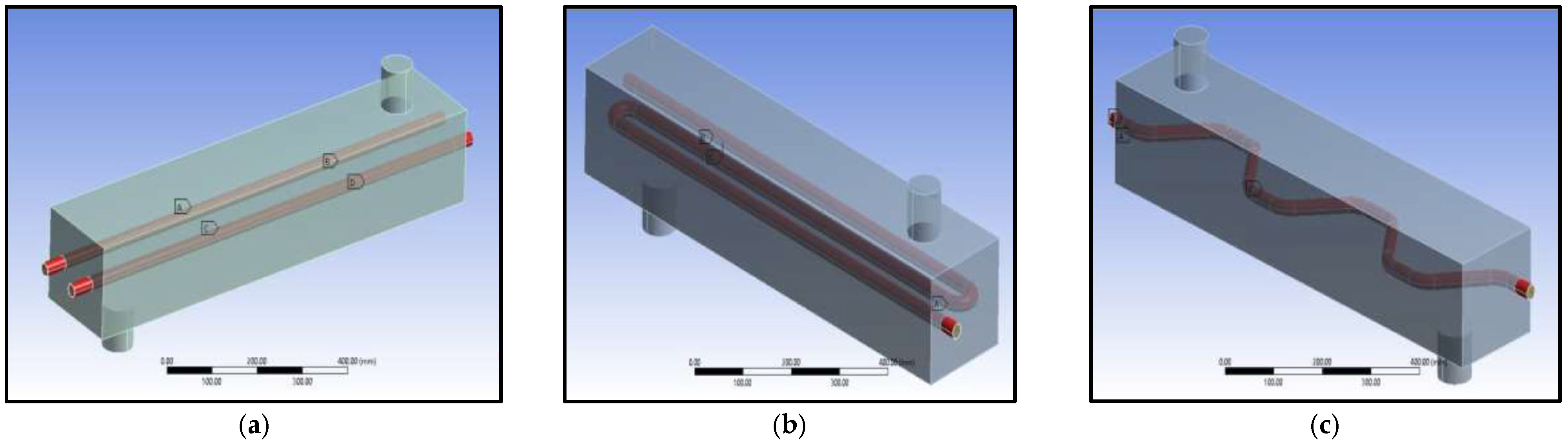
2.5.1. Geometry and Tube Pattern

A crucial part of the TCES reactor design process is optimising the heat transfer system, namely improving the transportation of energy generated within the TCES system to its intended applications. Heat exchangers facilitate this transfer by enabling a cooler fluid stream to come into thermal contact with a hotter fluid stream, effectively transferring heat from the latter to the former. As some of the most commonly used equipment in process engineering, heat exchangers give a moderately large surface area of heat transfer per given volume [67]. The necessity of thorough heat exchanger design is accredited to the importance of reducing energy costs and improving the energy recovery and resultant efficiency of the chemical process [68]. There are two essential groupings of heat exchangers as per their stream direction: parallel-stream (co-current) exchangers have both the hot and cold fluid streams flowing in the same direction; counter-stream (counter-current) exchangers use streams entering the exchanger from inverse closures and flowing in opposite directions [67]. Counter-current heat exchangers generally exchange the most heat by distributing the heat more evenly across the exchanger and therefore allow for maximum efficiency.
Fluidised beds have themselves been utilised as separate heat exchangers for certain processes due to their unique ability to rapidly transport heat and maintain a uniform temperature [61]. Non-contacting gas–solid fluidised bed heat exchangers operate using coils or tubes transporting fluid which run through a bed of solid particles; this allows for coolant fluid such as water or steam to be heated by recovering thermal energy from the hot solids. Criado et al. [57] use this technique in their own TCES process, where the fluidised bed reactor generating heat through CaO hydration is connected to a separate fluidised bed heat exchanger (FBHX). This is used to recover the sensible heat contained in the flow of hot solids exiting the reactor and is a separate heat recovery step to the primary exothermic heat production occurring in the TCES fluidised bed. The FBHX operates in counter-current flow to the water/steam flow [57]. Criado et al. refer to a heat exchanger inside the TCES fluidised bed used for steam production for primary heat recovery from the storage system, but no further detail is provided. Research has indicated that the incorporation of internal components, such as strategically positioned heat exchanger tubes and coils, within a fluidised bed reactor can notably enhance gas–solid contact [61]. This enhancement occurs as the heat exchanger tubing disrupts the formation of large bubbles within the bed, thereby mitigating gulf streaming and the resultant gross circulation of solids. Gulf streaming is the phenomenon where the movement of gas through the fluidised bed causes localised flow patterns, hence forming streams or channels which disrupt uniformity and ultimately hinder efficient mixing [61]. As a result, proper design of reactor internals can markedly elevate fluidisation quality to the extent that intricate gas inlet distributors become unnecessary. Moreover, the heat transfer coefficient for surfaces inside a fluidised bed is approximately four times higher than surfaces in the freeboard zone above the bed [61]. The technology relevant to this research is the use of a heat exchanger within the TCES fluidised bed reactor itself, whereby a heat transfer fluid (HTF) may recover heat by running counter-currently to the fluidising gas entering the reactor.
The heat transfer capabilities from a TCES fluidised bed reactor to a heat exchanger may be altered beyond stream direction, specifically through geometric design regarding tube pattern. Traditionally, heat exchanger tubing can be arranged in two ways: straight or helically coiled tubes. Helical coils provide an advantage over straight tubes due to their compact design and higher heat transfer coefficients [69]. The curvature of the coil generates a centrifugal force on the fluid within the pipe, leading to the formation of a secondary flow, where fluid near the inner wall of the coil is propelled towards the outer wall before circling back. This secondary flow promotes increased mixing, thereby enhancing both heat transfer and temperature uniformity [69,70]. Prabhanjan et al. [69] conducted an analysis on fluid–fluid heat exchangers, examining both coiled and straight-tubed configurations to assess their respective heat transfer coefficients. The helical coil used 10 turns of a 15.7 mm inner diameter copper pipe, with a wall thickness of 1.2 mm and no pitch. In comparison, the straight tube heat exchanger used a 17 mm inner diameter copper tube of length equivalent to the stretched length of the helical coil (6.38 m). Both heat exchangers were tested by being immersed in a water bath, with two bath temperatures being used (40 and 50 °C) and three flow rates within the exchanger pipes (5, 15, and 25 L/min). The research showed that the helical coil exhibited a more significant temperature rise compared to the straight tube. Additionally, increasing the flow rate led to a decreased temperature rise of the heat exchanger water in both configurations when the bath water temperature remained constant. It was therefore concluded that the enhanced temperature rise in the helical coil was solely attributable to the development of secondary flow; the passage of the hotter fluid from one side of the tube to the other accelerates the transfer of heat from the tube wall to the tube centre. The decrease in temperature rise with increased flow was attributed to the decreased residence time of the fluid in both tube configurations. As a result, the heat transfer coefficient was significantly affected by the coil pattern and the water bath temperature, though it was not affected by the flow rate. Indeed, the helical coil had an average heat transfer coefficient 1.16 and 1.43 times larger than that of the straight pipe, for bath temperatures of 40 and 50 °C, respectively [69]. This corresponds with more recent results from Chokphoemphun et al. [71], who tested the effect of air flow rate through a helical coil heat exchanger inside a rice husk fluidised bed combustor. This research used a stainless-steel coil of diameter 25.4 mm and coil pitch length 50.8 mm. Testing was performed at four different air mass flow rates entering the coiled heat exchanger (6.0248, 6.8077, 7.8163, and 8.8646 kg/h), and co- and counter-current flow through the coil were also compared. The setup for this research should also be noted, where the heat exchanger coil was positioned in a freeboard zone situated above the rice husk combustor, as opposed to being coiled in and around the fluidised bed itself. This arrangement led to a temperature reduction of approximately 214 °C from that inside the combustor itself and within the freeboard zone, where the heat transfer was taking place. It was observed that the outlet temperature of the coil tended to decrease with an increase in air flow rate through the coil. Moreover, operation with co-current flow exhibited higher heat transfer rates, surpassing those of counter-current flow by 29 J/s.
With regard to fluidised bed reactors with immersed heat exchanger tubes, Angerer et al. [72] conducted the design of an industrial-scale CaO/Ca(OH)2 TCES reactor. The conceptual design of the reactor is shown in Figure 9. A gas distributor plate with a high number of nozzles is used to distribute fluidisation gas uniformly throughout the solid particles, resulting in a dense bubbling bed. There is a continuous feed of solid particles entering and exiting the reactor bed, with a high-temperature filter system used to ensure that particles and fines remain within the reactor. Baffles are integrated within the bed to improve the residence time distribution and allow for solid particles to be guided from inlet to outlet, with the orange arrows in Figure 9 illustrating particle movement. Heat exchanger tubes are packed into the solid bed as densely as possible; individual ‘S’ pattern tubes are used, with multiple in- and outlets through the reactor sides. The model is designed to be scaled up, with length, width, and number of baffles easily adapted for suitable storage design. It was concluded that the heat transfer between the fluidised bed and the HTF in the heat exchangers (water) was the most influential factor on reactor performance. This is indicative that heat transfer controls the reaction in an industrial-scale reactor, as opposed to chemical kinetics or mass transfer, as previously concluded for lab-scale reactors [38,47]. Indeed, it was found that a 40 m3 bed (corresponding to ~100 m3 total reactor volume) can deliver a power output of ~15 MW, generating steam at 100 bar/450 °C during discharge [72].
Figure 9. Reactor design of a continuous TCES fluidised bed reactor, where the orange arrows signify particle movement through the reactor [72].
Energies 17 03389 g009
Besides straight or coiled tubing, innovation has introduced the potential for ‘zigzag’ pattern tubing; Kishan et al. [67] used computational fluid dynamics (CFD) software ANSYS 14.0 to undergo comparison between parallel, ‘S’, and zigzag patterns in shell-and-tube heat exchangers. Parallel tubing utilised two identical heat exchanger tubes in parallel (straight pattern). ‘S’ pattern tubing is typical for shell-and-tube heat exchangers and is most comparable to helical coils, using one heat exchanger tube that coils around the inside of the container. Zigzag tubing utilised one heat exchanger tube-shaped with alternating angles to come into thermal contact with a larger surface area of the container. Each of these tube patterns is presented in Figure 10. In the CFD model, convective heat exchange and no-slip criteria were specified, with cold water (inside tube) and hot water (inside shell) being defined. The tube material was selected to be copper due to its high thermal conductivity, and the shell material was specified as an aluminium alloy. Using counter-current flow and identical boundary conditions excluding tube patterns, the study found that the zigzag tube pattern gave optimal heat transfer in comparison to its counterparts. Using a heat exchanger inlet temperature of 12 °C and shell inlet temperature of 90 °C, the outlet of the parallel tubed heat exchanger increased to 21 °C, while the ‘S’ and zigzag pattern tubes increased to 35 °C and 54 °C, respectively [67].

2.5.2. Heat Transfer Fluids

Heat transfer fluids (HTF) play a crucial role in the operation of heat exchangers, significantly impacting overall performance and efficiency. Given the substantial volume of HTF required to circulate through the heat exchanger in a fluidised bed, it becomes imperative to minimise cost while maximising effectiveness. Desired characteristics of an HTF include [73] low melting point, high boiling point and thermal stability, low vapour pressure (<1 atm) at high temperatures, low corrosion with metal alloys used to contain the HTF, low viscosity, high thermal conductivity, high heat capacity for energy storage, and low cost. HTFs can generally be categorised into six main groups: air, water/steam, thermal oils, organics, molten salts, and liquid metals. These are presented in Table 4 [73] with their relevant thermal and physical properties. As a gas, the unique advantage of air is not only its abundance and cost-free nature, but also its particularly low dynamic viscosity. This gives air particularly good flow properties within pipelines. Such significant advantages are arguably more substantial than the drawbacks of using air as an HTF, such as a comparatively low thermal conductivity next to molten salts or liquid metals [74]. Almost equally abundant and inexpensive as air is water. The additional unique advantage of using water/steam as an HTF is its utilisation as a working fluid in district heating networks; employing water/steam for both HTF and the working fluid streamlines the TCES-DH system, thus enhancing efficiency and reducing the cost of electricity production. Feldhoff et al. [75] conducted research into direct steam generation through solar thermal power plant technology, demonstrating that the levelized cost of energy (LCOE) was 11% lower in direct steam generating systems utilising water/steam as the sole fluid, compared to systems using oil-based HTFs. Furthermore, considering its considerably low cost, the thermal conductivity and heat capacity of water vapour are competitive with its counterparts, as outlined in Table 4. The only alternatives with significantly higher values in this regard are the liquid metals, which are substantially more expensive at 2 or even 13 USD/kg [76]. Indeed, the operating temperatures of the CaO/Ca(OH)2 and MgO/Mg(OH)2 TCES systems, ranging between 450–500 °C and 250–450 °C, respectively, render the thermal oils and organic HTF listed unsuitable for this application. The molten salts and liquid metals given are likewise considered unsuitable due to the logistical challenges associated with handling materials with higher melting points. Storing, transporting, and preparing such substances entail inconvenience and additional costs, rendering these impractical options for the intended application.
Despite having a relatively high thermal efficiency, the critical drawback of using water as an HTF is its evaporation into low-pressure steam with limited superheat at elevated temperatures. This is likely to cause later issues due to the steam being a lower grade by nature and having incapabilities for lengthy transportation. The suitability of liquid water is therefore determined depending on the operating temperatures required by the individual TCES system. A solution for this is to optimise operating temperatures by mixing water with synthetic liquids such as propylene glycol. With a boiling point of 188 °C [77], propylene glycol is a suitable addition to water as an HTF due to their similar properties such as lack of corrosivity and toxicity. Despite this, propylene glycol is more viscous than water at 0.0486 Pa·s, resulting in higher pumping requirements. Further, the thermal conductivity and specific heat capacity of water at 25 °C are 0.6 W/m·K and 4.18 kJ/kg·K, respectively; these are relatively higher than that of propylene glycol at 0.21 W/m·K and 2.49 kJ/kg·K, resulting in a reduction in heat transfer when a water–glycol mixture is formed [77]. A consideration into the benefits of pure vs. glycol–mixed water is therefore necessary depending on the TCES material and subsequent operating conditions being used.

2.6. Enhancements

2.6.1. Nanomaterials and Coatings

Agglomeration during thermochemical cycling is common and can cause inhomogeneity, which in turn may result in permanent changes in bed characteristics, particularly in relation to heat and mass transport [78]. The Geldart group C classification of both magnesium and calcium hydroxides makes this especially relevant; calcium hydroxide in particular is prone to agglomeration and can result in plugging or channelling in fluidised bed reactors, as outlined previously [11,59]. Research has been executed to improve solid flowability through modification, a key example being nanostructured or composite coatings. This modification method theoretically decreases the van der Waals forces between the Ca(OH)2 particles, therefore reducing cohesiveness and enhancing flowability. Further advantages of nanomaterial coating include the improved stability and durability of TCES materials, and the ability to have specific properties tailored to the requirements of the TCES system. Utilising coatings provides protection against degradation and sintering, as is common in magnesium hydroxide particles [51], thus prolonging particle lifespan and subsequent system durability. With some nanomaterials, it is possible to engineer properties such as improved thermal conductivity, phase stability, and chemical compatibility, which allows for flexibility regarding system performance.
Roßkopf et al. [78] coated calcium hydroxide particles with nanostructured SiO2 and monitored system cycling with regard to side reactions, particle surface stability, and various coating configurations. It was highlighted that any additives to TCES must maintain their reducing effect during intensive cycling. In this case, temperatures up to 600 °C must be resisted and impact efficiency maintained, regardless of the size and shape change of the coated particles during chemical reaction. It was found that the use of SiO2 effectively prevented the agglomeration of calcium hydroxide, although reactivity was reduced due to the formation of unreactive side products. Moreover, particle size distributions (PSDs) illustrated the increased agglomeration of pure and 1 w% SiO2 coating compared to the 10 w% SiO2. Repeated cycling highlighted fluctuation in particle surface characteristics during reaction and the detachment of coatings due to mechanical stresses within the reactor, alongside SiO2/Ca(OH)2 side reactions. Intensified mixing between the SiO2 and calcium hydroxide prior to cycling proved to strongly enhance the formation of side products, with reduced side conversion observed at lower mixing intensities. It is hypothesised that less thorough mixing with the nanomaterial caused Ca(OH)2 particle adherence to the surface of SiO2 aggregates, partially concealing them during reaction cycles. The reverse is observed following high-intensity mixing, which resulted in a severance of the SiO2 agglomerates, forcing the nanoparticles to accumulate on the surface of the Ca(OH)2 particles. Similarly, Mejia et al. [40] used a moving bed TCES reactor to investigate two encapsulated storage materials: ceramic-encapsulated CaO granules and Ca(OH)2 granules coated with Al2O3 nanostructured particles. Both materials underwent six hydration/dehydration cycles in two batches to analyse cycling stability and performance, with particular attention paid to flowability through the reactor and granular structural integrity. Notably, the size of the Ca(OH)2 granules was particularly large with diameters 1–4 mm, hitherto unexplored in this research. Nonetheless, the runs were successful, and the ceramic-shelled granules maintained flowability and shape even after repeated cycles, albeit exhibiting some cracking and degradation of the ceramic shell. However, a decline in reaction efficiency and incomplete conversion were observed; this is supposedly attributed to mass transport resistance and a significantly reduced energy density, both inflicted by the ceramic shell. Comparatively, the Al2O3 nanomaterial runs mirrored those with unmodified Ca(OH)2 granules regarding both reaction performance and energy density. Indeed, where minimal cycling caused extreme degradation of the pure granules, the Al2O3-coated granules retained structural integrity after several cycles.
With regards to magnesium hydroxide, Shkatulov et al. [79] synthesised a composite material by precipitation of Mg(OH)2 particles within the pores of expanded magnesium–aluminium–iron silicate, or ‘vermiculite’. This mineral is advantageous due to its large pore volume (3.0–3.5 cm3/g), which allows for the deposition of large volumes of hydroxide. Most notably, there is sufficient capacity for the swelling and shrinkage which is typical of repeat hydration/dehydration cycles. The objective of this synthesis was to alter the magnesium hydroxide, therefore increasing its suitability for middle-temperature heat and improving the accordance of the reaction temperature with that of the heat to be stored. This proved successful, with a composite capable of storing heat between 260 and 300 °C being formed. Thermogravimetric analysis (TGA) and differential scanning calorimetry (DSC) techniques verified the reduction in the decomposition temperature of the confined Mg(OH)2 by ~50 °C. A kinetic study of the decomposition reaction of both pure and precipitated magnesium hydroxide revealed a significant acceleration of the decomposition reaction inside the vermiculite pores. However, only five cycles were completed, and further testing is therefore required.

2.6.2. Doping

The manipulation of undesirable material properties may also be achieved through doping. While nanomaterials and composite coatings do this through encasing the target material and leaving it intact in its original state, doping involves the formation of a new material through synthesis. A small quantity of the dopant is combined with the material undergoing modification to increase material stability, thermal conductivity, and/or reaction conversion [80]. For hydroxides undergoing TCES, an appealing modification is a reduction in operating temperature due to the lower temperatures of waste heat supply and requirements for DH networks. Slimani et al. [81] conducted a recent study to reduce the dehydration temperature of Mg(OH)2 through the 5% doping of magnesium with transition metal elements zinc (Zn), cobalt (Co), nickel (Ni), manganese (Mn), and copper (Cu). These dopants were selected based on their electronegativities and radii, the criteria being that they match or exceed the ionic radius of Mg and exhibit higher electronegativity. Equation (12) gives the formula for the new material formed after the addition of dopant M, where the mole fraction of the dopant x = 0.05:
M g 1 x M x ( O H ) 2  
The doping was achieved through the coprecipitation of magnesium with the relevant transition metal. TGA and DSC analysis showed that the dehydration of all materials occurred in a single step, where the water molecules were released and the oxide remained. The mass loss for all materials was maintained at ~30% which aligns with the theoretical water content of the investigated hydroxides, therefore confirming complete hydration; this is indicative of the doped materials not altering from the dehydration pathway of pure Mg(OH)2, but shifting it to a lower value. Indeed, the influence of doping on dehydration temperature was apparent. Cobalt doping resulted in the largest decrease from that of pure Mg(OH)2 (360 °C) at approximately −70 °C, followed by manganese (−47.8 °C) and zinc (−40 °C). Following this, the hydration of the doped materials gave a substantial increase in conversion fraction, with values greater than 80% for cobalt, zinc, and manganese, compared to 65% for pure magnesium hydroxide. It can therefore be concluded that these synthesised materials greatly improved both reactivity and storage capacity, therefore positively impacting the efficiency and performance of the MgO/Mg(OH)2 system. Finally, the cyclability of the synthesised materials was also improved, with indications of advanced stability in all doped hydroxides for six repeated hydration/dehydration cycles. In particular, the zinc sample maintained a −4.11% conversion loss from the 4th to 6th cycles, in comparison to pure Mg(OH)2 which gives a −12.62% loss in the 4th and −13.1% by the 6th. While the cycling showed consistent dehydration behaviour, there were some slight discrepancies in the hydration rates of the materials. However, the results clearly displayed key enhancements of magnesium hydroxide by reducing operating temperature, maintaining energy storage density, and improving hydration rate and cycling stability.
Comparatively, the effect of lithium (Li) doping on the CaO/Ca(OH)2 system regarding heat storage speed and capacity was studied by Yan and Zhao [81]. A ball grinding method was used to dope the Ca(OH)2 with Li at different Li/Ca molar ratios: 2, 5, 10, and 30%. Four samples of pure Ca(OH)2 and each molar ratio were prepared, and the endothermic dehydration process was observed at the heating rate of 15 °C/min. The duration needed to achieve a 40% conversion was observed, initially with 30% Li taking 370 s and progressing sequentially, until 2% Li at 440 s and pure Ca(OH)2 at 476 s. It is apparent that an increase in Li content resulted in a reduction in the time required for heat storage (dehydration), thus demonstrating an improved heat storage efficiency. Heat storage capacity is determined by the reaction enthalpy and specific heat capacity of the material. It was proven that the doping had little influence on the heat storage capacity of the CaO/Ca(OH)2 system. The pure Ca(OH)2 reaction enthalpy was measured here as 106.4 kJ/mol, with the 5% Li-doped sample giving an almost identical enthalpy of 106.5 kJ/mol after DSC testing. Specific heat capacity also showed little change overall, as that of Ca(OH)2 was slightly reduced after doping and CaO slightly increased. The same study analysed the kinetic process of the Li-doped calcium hydroxide, revealing a division into two stages once the molar fraction reacted reached 0.3. This is hypothesized to stem from the influence of Li atoms on the atoms within the Ca(OH)2 molecule beyond a specific interatomic distance [81].

3. Conclusions

A comprehensive review of district heating and thermochemical energy storage systems has been undertaken, detailing material characterisation and enhancement, reactor configuration and optimisation, and heat transfer efficiency. It has been concluded that the UK buildings sector is vastly disinclined regarding building decarbonisation, with a vital transformation needed to replace natural gas boilers by their scheduled 2025 ban, and to attain Net Zero requirements by 2050. Low-carbon district heating is a crucial component in this progression, with the potential to utilise industrial waste heat to provide space heating and hot water in domestic heating networks. Thermal energy storage is proposed to overcome the variable heating demand barriers imposed by district heating, with sensible, latent, and thermochemical energy storage explored. Despite traditional dependence on sensible storage, thermochemical storage is found to be ten times more energy efficient, and five times more so than latent. The elevated energy density and lack of thermal losses of thermochemical energy storage make it particularly appealing for the unpredictable nature of district heating demand. Existing sensible-supplied district heating also suffers high space requirements, investment costs, and heat losses.
With their high energy densities, optimal operating conditions, cycling stability, availability, and use of water vapour as a reactant, calcium and magnesium hydroxide are highly attractive for thermochemical energy storage. The calcium hydroxide system is determined to be optimal at lower temperatures within its operating range, with high H2O partial pressures optimising energy efficiency. Repeated cycling of calcium hydroxide systems also instigated significant agglomeration, with nanomaterial and composite coatings explored as an option to reduce cohesiveness between particles. Potential examples include nanostructured silicon oxide, ceramic encapsulation, and nanostructured aluminium oxide, though low-intensity mixing is advised for the former. Magnesium hydroxide is optimal at 250–450 °C and research has shown that these thermochemical systems may be greatly improved by using smaller diameter particles. Not only does this reduce agglomeration but also improves prolonged cycling, with slower hydration of magnesium oxide also recommended for agglomeration and fracturing reduction. Doping to alter material qualities is also explored, with a dehydration temperature reduction in magnesium hydroxide found to be optimal using transition metal doping. Particular transition metal dopants of interest were cobalt, zinc, and manganese.
Hydration/dehydration cycling can be undertaken in fixed, moving, or fluidised bed reactors. While fixed beds are commonly preferred for their simplicity, they suffer from inherent heat and mass transfer limitations, and their batch operation deems them unsuitable for district heating integration. Moving bed reactors offer improved heat and mass transfer capabilities, consequently enhancing heat capacity. However, despite their advantage over fixed beds, moving beds are susceptible to shear and inadequate mixing due to increased agglomeration, particularly with finer particles. Fluidised beds are therefore considered due to their particularly high heat transfer coefficients with enhanced mixing and uniformity, and resultantly improved fluid–particle contact. The operation of both relevant hydroxide TCES systems in fluidised bed reactors is evaluated, with variables such as reactor inner diameter, material mass, and inlet gas velocity considered for their effect on the processes. It was found that a reduced reactor diameter, larger material mass in the bed, and larger inlet gas velocity result in improved heat transfer efficiency within the system. The addition of inert easy-to-fluidise particles was found to somewhat improve agglomeration issues within the reactor, although a reduced energy density is also observed.
The optimisation of heat transfer from the thermochemical reactor to district heat working fluid is largely down to the heat exchange process within the system. Hence, tubing configuration and heat transfer fluids are evaluated for heat and mass transfer improvement. Both heat transfer and fluid–solid contact are said to be enhanced by appropriately placed heat exchanger coils/tubing within the fluidised bed, thus elevating fluidisation quality by reducing cohesiveness between particles. An increase in HTF flow rate is also said to reduce its rise in temperature. Helical coil heat exchangers are largely regarded as advantageous over alternative configurations due to their formation of a secondary flow, and increased mixing, as a result of centrifugal force. Zigzag tubing is also shown to exceed straight and S tubing when undergoing heat transfer comparison. Assessment of various heat transfer fluids concluded water as particularly advantageous owing to its abundance and low cost, although appropriate alternatives and modifications (water–glycol mixtures) require further consideration.
Waste heat from industrial processes such as the Nottingham EfW incinerator provides ample opportunity for sustainable and productive TCES-DH supply. Utilising this heat would allow for the modernisation and efficiency enhancement of existing DH systems, in addition to driving innovative advancement to DH technology, and thus advancing towards UK decarbonisation. Further research is therefore proposed for the development of a high-density, efficient, and compact fluidised thermochemical energy storage system for district heating integration. Material optimisation of magnesium and calcium hydroxides would allow for pilot-scale reactor development and testing, employing the utilisation of both fluidisation and anti-agglomeration technologies such as nanomaterial coatings and doping. The embedding of a helical coil heat exchanger within the reactor bed would introduce a novel concept to TCES development, allowing for improved heat transfer and fluid–solid contact through secondary flow and reduced particle cohesiveness. Optimisation and integration of the reviewed technologies and materials have the potential to significantly advance the adoption of effective TCES systems for UK district heating networks.

Author Contributions

Conceptualisation, S.R.-L., J.D., M.W., J.C. and R.B.; writing—original draft preparation, S.R.-L.; writing—review and editing, S.R.-L., J.D. and M.W.; supervision, J.D.; project administration, J.D.; funding acquisition, J.D. All authors have read and agreed to the published version of the manuscript.

Funding

This research was supported by the UK Engineering and Physical Sciences Research Council (EPSRC) Grant (No. EP/V041452/1).

Data Availability Statement

Not applicable.

Conflicts of Interest

The authors declare no conflicts of interest.

References

  1. Mahon, H.; O’Connor, D.; Friedrich, D.; Hughes, B. A review of thermal energy storage technologies for seasonal loops. Energy 2022, 239, 122207. [Google Scholar] [CrossRef]
  2. Asumadu-Sarkodie, S.; Owusu, P.A. Carbon dioxide emissions, GDP, energy use, and population growth: A multivariate and causality analysis for Ghana, 1971–2013. Environ. Sci. Pollut. Res. 2016, 23, 13508–13520. [Google Scholar] [CrossRef]
  3. Gielen, D.; Boshell, F.; Saygin, D.; Bazilian, M.D.; Wagner, N.; Gorini, R. The role of renewable energy in the global energy transformation. Energy Strategy Rev. 2019, 24, 38–50. [Google Scholar] [CrossRef]
  4. IEA Technology Collaboration Programmes (TCPs). Available online: https://nachhaltigwirtschaften.at/en/iea/technologyprogrammes/ (accessed on 9 April 2024).
  5. Woolnough, D. Waste Heat Recovery. In Thermopedia; Begel House Inc.: Danbury, CT, USA, 2011. [Google Scholar] [CrossRef]
  6. Albert, M.D.A.; Bennett, K.O.; Adams, C.A.; Gluyas, J.G. Waste heat mapping: A UK study. Renew. Sustain. Energy Rev. 2022, 160, 112230. [Google Scholar] [CrossRef]
  7. Papapetrou, M.; Kosmadakis, G.; Cipollina, A.; La Commare, U.; Micale, G. Industrial waste heat: Estimation of the technically available resource in the EU per industrial sector, temperature level and country. Appl. Therm. Eng. 2018, 138, 207–216. [Google Scholar] [CrossRef]
  8. Werner, S. District heating and cooling in Sweden. Energy 2017, 126, 419–429. [Google Scholar] [CrossRef]
  9. Climate Change Committee. Net Zero—Technical Report. Available online: https://www.theccc.org.uk/publication/net-zero-technical-report/ (accessed on 9 April 2024).
  10. Guelpa, E.; Verda, V. Thermal energy storage in district heating and cooling systems: A review. Appl. Energy 2019, 252, 113474. [Google Scholar] [CrossRef]
  11. Pardo, P.; Deydier, A.; Anxionnaz-Minvielle, Z.; Rougé, S.; Cabassud, M.; Cognet, P. A review on high temperature thermochemical heat energy storage. Renew. Sustain. Energy Rev. 2014, 32, 591–610. [Google Scholar] [CrossRef]
  12. Cabeza, L.F.; Martorell, I.; Miró, L.; Fernández, A.I.; Barreneche, C. 1—Introduction to thermal energy storage (TES) systems. In Advances in Thermal Energy Storage Systems; Cabeza, L.F., Ed.; Woodhead Publishing Series in Energy; Woodhead Publishing: Sawston, UK, 2015; pp. 1–28. [Google Scholar] [CrossRef]
  13. Xu, C.; Yu, Z.; Xie, Y.; Ren, Y.; Ye, F.; Ju, X. Study of the hydration behavior of zeolite-MgSO4 composites for long-term heat storage. Appl. Therm. Eng. 2018, 129, 250–259. [Google Scholar] [CrossRef]
  14. Gbenou, T.R.S.; Fopah-Lele, A.; Wang, K. Macroscopic and microscopic investigations of low-temperature thermochemical heat storage reactors: A review. Renew. Sustain. Energy Rev. 2022, 161, 112152. [Google Scholar] [CrossRef]
  15. GOV.UK. Energy Consumption in the UK 2020. Available online: https://www.gov.uk/government/statistics/energy-consumption-in-the-uk-2020 (accessed on 11 April 2024).
  16. District Energy|Enviroenergy. Available online: https://enviroenergy.co.uk/about-us/district-energy/ (accessed on 11 April 2024).
  17. Albert, D. District Heating in Norway: How Norwegian Cities Keep Warm, Life in Norway. Available online: https://www.lifeinnorway.net/district-heating-in-norway/ (accessed on 11 April 2024).
  18. Fjernvarme, 2015—Fjernvarmebalanse. GWh. ssb.no. Available online: https://www.ssb.no/energi-og-industri/statistikker/fjernvarme/aar/2021-05-26 (accessed on 11 April 2024).
  19. Di Lucia, L.; Ericsson, K. Low-carbon district heating in Sweden—Examining a successful energy transition. Energy Res. Soc. Sci. 2014, 4, 10–20. [Google Scholar] [CrossRef]
  20. Hall, T.; Vidén, S. The Million Homes Programme: A review of the great Swedish planning project. Plan. Perspect. 2005, 20, 301–328. [Google Scholar] [CrossRef]
  21. Heat Networks Planning Database|BEIS & Barbour ABI. Available online: https://data.barbour-abi.com/smart-map/repd/beis/?type=heat_network (accessed on 23 May 2024).
  22. GOV.UK. Heat Networks. Available online: https://www.gov.uk/government/collections/heat-networks (accessed on 11 April 2024).
  23. Ambrose, J.; Correspondent, J.A.E. UK Government Backs Plan to Ban Gas and “Hydrogen-Ready” Boilers. The Guardian. 13 December 2023. Available online: https://www.theguardian.com/business/2023/dec/13/uk-government-backs-plan-ban-gas-hydrogen-ready-boilers-newbuilds-2025 (accessed on 11 April 2024).
  24. Nottingham City District Heating Scheme. Available online: https://www.vitalenergi.co.uk/our-work/nottingham-city-district-heating/ (accessed on 11 April 2024).
  25. Desai, F.; Prasad, J.S.; Muthukumar; Rahman, M.M. Thermochemical energy storage system for cooling and process heating applications: A review. Energy Convers. Manag. 2021, 229, 113617. [Google Scholar] [CrossRef]
  26. Khan, Z.; Khan, Z.; Ghafoor, A. A review of performance enhancement of PCM based latent heat storage system within the context of materials, thermal stability and compatibility. Energy Convers. Manag. 2016, 115, 132–158. [Google Scholar] [CrossRef]
  27. Kalaiselvam, S.; Parameshwaran, R. Thermal Energy Storage Technologies for Sustainability: Systems Design, Assessment and Applications; Elsevier: Amsterdam, The Netherlands, 2014. [Google Scholar]
  28. Abedin, A.H.; Rosen, M.A. A Critical Review of Thermochemical Energy Storage Systems. Open Renew. Energy J. 2011, 4, 42–46. Available online: https://benthamopen.com/ABSTRACT/TOREJ-4-42 (accessed on 9 April 2024). [CrossRef]
  29. Böhm, H.; Lindorfer, J. Techno-economic assessment of seasonal heat storage in district heating with thermochemical materials. Energy 2019, 179, 1246–1264. [Google Scholar] [CrossRef]
  30. Xu, J.; Wang, R.Z.; Li, Y. A review of available technologies for seasonal thermal energy storage. Sol. Energy 2014, 103, 610–638. [Google Scholar] [CrossRef]
  31. Marie, L.F.; Landini, S.; Bae, D.; Francia, V.; O’Donovan, T.S. Advances in thermochemical energy storage and fluidised beds for domestic heat. J. Energy Storage 2022, 53, 105242. [Google Scholar] [CrossRef]
  32. Carrillo, A.J.; Moya, J.; Bayón, A.; Jana, P.; Romero, M.; Gonzalez-Aguilar, J.; Serrano, D.P.; Pizarro, P.; Coronado, J.M. Thermochemical energy storage at high temperature via redox cycles of Mn and Co oxides: Pure oxides versus mixed ones. Sol. Energy Mater. Sol. Cells 2014, 123, 47–57. [Google Scholar] [CrossRef]
  33. Felderhoff, M.; Bogdanović, B. High Temperature Metal Hydrides as Heat Storage Materials for Solar and Related Applications. Int. J. Mol. Sci. 2009, 10, 325. [Google Scholar] [CrossRef]
  34. Barker, R. The reversibility of the reaction CaCO3 ⇄ CaO+CO2. J. Appl. Chem. Biotechnol. 1973, 23, 733–742. [Google Scholar] [CrossRef]
  35. Aihara, M.; Nagai, T.; Matsushita, J.; Negishi, Y.; Ohya, H. Development of porous solid reactant for thermal-energy storage and temperature upgrade using carbonation/decarbonation reaction. Appl. Energy 2001, 69, 225–238. [Google Scholar] [CrossRef]
  36. Ervin, G. Solar heat storage using chemical reactions. J. Solid State Chem. 1977, 22, 51–61. [Google Scholar] [CrossRef]
  37. Criado, Y.A.; Alonso, M.; Abanades, J.C. Kinetics of the CaO/Ca(OH)2 Hydration/Dehydration Reaction for Thermochemical Energy Storage Applications. Ind. Eng. Chem. Res. 2014, 53, 12594–12601. [Google Scholar] [CrossRef]
  38. Schaube, F.; Wörner, A.; Tamme, R. High Temperature Thermochemical Heat Storage for Concentrated Solar Power Using Gas–Solid Reactions. J. Sol. Energy Eng. 2011, 133, 031006. [Google Scholar] [CrossRef]
  39. Mejia, A.C.; Afflerbach, S.; Linder, M.; Schmidt, M. Experimental analysis of encapsulated CaO/Ca(OH)2 granules as thermochemical storage in a novel moving bed reactor. Appl. Therm. Eng. 2020, 169, 114961. [Google Scholar] [CrossRef]
  40. Fahim, M.A.; Ford, J.D. Energy storage using the BaO/sub 2/-BaO reaction cycle. Chem. Eng. J. Lausanne Switz. 1983, 27, 21–28. [Google Scholar] [CrossRef]
  41. Neises, M.; Tescari, S.; de Oliveira, L.; Roeb, M.; Sattler, C.; Wong, B. Solar-heated rotary kiln for thermochemical energy storage. Sol. Energy 2012, 86, 3040–3048. [Google Scholar] [CrossRef]
  42. Wentworth, W.E.; Chen, E. Simple thermal decomposition reactions for storage of solar thermal energy. Sol. Energy 1976, 18, 205–214. [Google Scholar] [CrossRef]
  43. Chen, X.; Jin, X.; Liu, Z.; Ling, X.; Wang, Y. Experimental investigation on the CaO/CaCO3 thermochemical energy storage with SiO2 doping. Energy 2018, 155, 128–138. [Google Scholar] [CrossRef]
  44. Azpiazu, M.N.; Morquillas, J.M.; Vazquez, A. Heat recovery from a thermal energy storage based on the Ca(OH)2/CaO cycle. Appl. Therm. Eng. 2003, 23, 733–741. [Google Scholar] [CrossRef]
  45. Irabien, A.; Toquero, A.; Ortiz, M.I. Kinetic behaviour of non-isothermal lime hydration. Chem. Eng. J. 1989, 40, 93–99. [Google Scholar] [CrossRef]
  46. Schaube, F.; Koch, L.; Wörner, A.; Müller-Steinhagen, H. A thermodynamic and kinetic study of the de- and rehydration of Ca(OH)2 at high H2O partial pressures for thermo-chemical heat storage. Thermochim. Acta 2012, 538, 9–20. [Google Scholar] [CrossRef]
  47. Galwey, A.K.; Laverty, G.M. A kinetic and mechanistic study of the dehydroxylation of calcium hydroxide. Thermochim. Acta 1993, 228, 359–378. [Google Scholar] [CrossRef]
  48. Prasad, J.S.; Muthukumar; Desai, F.; Basu, D.N.; Rahman, M.M. A critical review of high-temperature reversible thermochemical energy storage systems. Appl. Energy 2019, 254, 113733. [Google Scholar] [CrossRef]
  49. Kato, Y.; Nakahata, J.; Yoshizawa, Y. Durability characteristics of the hydration of magnesium oxide under repetitive reaction. J. Mater. Sci. 1999, 34, 475–480. [Google Scholar] [CrossRef]
  50. Kato, Y.; Kobayashi, K.; Yoshizawa, Y. Durability to repetitive reaction of magnesium oxide/water reaction system for a heat pump. Appl. Therm. Eng. 1998, 18, 85–92. [Google Scholar] [CrossRef]
  51. Filippou, D.; Katiforis, N.; Papassiopi, N.; Adam, K. On the kinetics of magnesia hydration in magnesium acetate solutions. J. Chem. Technol. Biotechnol. 1999, 74, 322–328. [Google Scholar] [CrossRef]
  52. Pan, Z.; Zhao, C.Y. Dehydration/hydration of MgO/H2O chemical thermal storage system. Energy 2015, 82, 611–618. [Google Scholar] [CrossRef]
  53. Yan, J.; Yang, B.W.; Zhao, C.Y. Investigation of hydration/dehydration processes in a fluidized bed reactor using MgO/Mg(OH)2 thermochemical energy storage system. Sol. Energy 2022, 231, 630–645. [Google Scholar] [CrossRef]
  54. Kato, Y.; Yamashita, N.; Kobayashi, K.; Yoshizawa, Y. Kinetic study of the hydration of magnesium oxide for a chemical heat pump. Appl. Therm. Eng. 1996, 16, 853–862. [Google Scholar] [CrossRef]
  55. Yan, J.; Zhao, C.Y. Experimental study of CaO/Ca(OH)2 in a fixed-bed reactor for thermochemical heat storage. Appl. Energy 2016, 175, 277–284. [Google Scholar] [CrossRef]
  56. Criado, Y.A.; Alonso, M.; Abanades, J.C.; Anxionnaz-Minvielle, Z. Conceptual process design of a CaO/Ca(OH)2 thermochemical energy storage system using fluidized bed reactors. Appl. Therm. Eng. 2014, 73, 1087–1094. [Google Scholar] [CrossRef]
  57. Shirzad, M.; Karimi, M.; Silva, J.A.C.; Rodrigues, A.E. Moving Bed Reactors: Challenges and Progress of Experimental and Theoretical Studies in a Century of Research. Ind. Eng. Chem. Res. 2019, 58, 9179–9198. [Google Scholar] [CrossRef]
  58. Pardo, P.; Anxionnaz-Minvielle, Z.; Rougé, S.; Cognet; Cabassud, M. Ca(OH)2/CaO reversible reaction in a fluidized bed reactor for thermochemical heat storage. Sol. Energy 2014, 107, 605–616. [Google Scholar] [CrossRef]
  59. Valverde, J.M.; Pontiga, F.; Soria-Hoyo, C.; Quintanilla, M.A.; Moreno, H.; Duran, F.J.; Espin, M.J. Improving the gas–solids contact efficiency in a fluidized bed of CO2 adsorbent fine particles. Phys. Chem. Chem. Phys. 2011, 13, 14906–14909. [Google Scholar] [CrossRef] [PubMed]
  60. Kunii, D.; Levenspiel, O. Fluidization Engineering; Butterworth-Heinemann: Oxford, UK, 1991. [Google Scholar]
  61. Siedlecki, M.; De Jong, W.; Verkooijen, A.H.M. Fluidized Bed Gasification as a Mature And Reliable Technology for the Production of Bio-Syngas and Applied in the Production of Liquid Transportation Fuels—A Review. Energies 2011, 4, 389. [Google Scholar] [CrossRef]
  62. Geldart, D. Types of gas fluidization. Powder Technol. 1973, 7, 285–292. [Google Scholar] [CrossRef]
  63. Rosa, T.; Lin, J.; Pfeffer, R.; Nielsen, D.; Dai, L. Synthesis of Amine-Modified Aerogel Sorbents and Metal-Organic Framework-5 (MOF-5) Membranes for Carbon Dioxide Separation; Arizona State University: Tempe, AZ, USA, 2010. [Google Scholar]
  64. Trung Bui, T.; Anh Duc, L. Determination on Fluidization Velocity Types of the Continuous Refined Salt Fluidized Bed Drying. In Current Drying Processes; InTech Open: London, UK, 2020. [Google Scholar] [CrossRef]
  65. Cot-Gores, J.; Castell, A.; Cabeza, L.F. Thermochemical energy storage and conversion: A-state-of-the-art review of the experimental research under practical conditions. Renew. Sustain. Energy Rev. 2012, 16, 5207–5224. [Google Scholar] [CrossRef]
  66. Kishan, R.; Singh, D.; Sharma, A.K. CFD Analysis of Heat Exchanger Models Design Using ANSYS Fluent. Int. J. Mech. Eng. Technol. 2020, 11, 1–9. Available online: https://papers.ssrn.com/abstract=3540077 (accessed on 5 May 2024). [CrossRef]
  67. Escobar, M.; Trierweiler, J.O. Optimal heat exchanger network synthesis: A case study comparison. Appl. Therm. Eng. 2013, 51, 801–826. [Google Scholar] [CrossRef]
  68. Prabhanjan, D.G.; Raghavan, G.S.V.; Rennie, T.J. Comparison of heat transfer rates between a straight tube heat exchanger and a helically coiled heat exchanger. Int. Commun. Heat Mass Transf. 2002, 29, 185–191. [Google Scholar] [CrossRef]
  69. Ruthven, D.M. The residence time distribution for ideal laminar flow in helical tube. Chem. Eng. Sci. 1971, 26, 1113–1121. [Google Scholar] [CrossRef]
  70. Chokphoemphun, S.; Eiamsa-ard, S.; Promvonge; Thongdaeng, S.; Hongkong, S. Heat transfer of a coil-tube heat exchanger in the freeboard zone of a rice husk fluidized-bed combustor. Int. Commun. Heat Mass Transf. 2021, 127, 105462. [Google Scholar] [CrossRef]
  71. Angerer, M.; Becker, M.; Härzschel, S.; Kröper, K.; Gleis, S.; Vandersickel, A.; Spliethoff, H. Design of a MW-scale thermo-chemical energy storage reactor. Energy Rep. 2018, 4, 507–519. [Google Scholar] [CrossRef]
  72. Vignarooban, K.; Xu, X.; Arvay, A.; Hsu, K.; Kannan, A.M. Heat transfer fluids for concentrating solar power systems—A review. Appl. Energy 2015, 146, 383–396. [Google Scholar] [CrossRef]
  73. Liu, M.; Belusko, M.; Tay, N.H.S.; Bruno, F. Impact of the heat transfer fluid in a flat plate phase change thermal storage unit for concentrated solar tower plants. Sol. Energy 2014, 101, 220–231. [Google Scholar] [CrossRef]
  74. Feldhoff, J.F.; Benitez, D.; Eck, M.; Riffelmann, K.-J. Economic potential of solar thermal power plants with direct steam generation compared with HTF plants. J. Sol. Energy Eng. Trans. ASME 2010, 132, 041001. [Google Scholar] [CrossRef]
  75. Fernández, A.G.; Ushak, S.; Galleguillos, H.; Pérez, F.J. Development of new molten salts with LiNO3 and Ca(NO3)2 for energy storage in CSP plants. Appl. Energy 2014, 119, 131–140. [Google Scholar] [CrossRef]
  76. CAS Common Chemistry. Available online: https://commonchemistry.cas.org/detail?cas_rn=57-55-6 (accessed on 30 May 2024).
  77. Roßkopf, C.; Afflerbach, S.; Schmidt, M.; Görtz, B.; Kowald, T.; Linder, M.; Trettin, R. Investigations of nano coated calcium hydroxide cycled in a thermochemical heat storage. Energy Convers. Manag. 2015, 97, 94–102. [Google Scholar] [CrossRef]
  78. Shkatulov, A.; Ryu, J.; Kato, Y.; Aristov, Y. Composite material “Mg(OH)2/vermiculite”: A promising new candidate for storage of middle temperature heat. Energy 2012, 44, 1028–1034. [Google Scholar] [CrossRef]
  79. Funayama, S.; Takasu, H.; Zamengo, M.; Kariya, J.; Kim, S.T.; Kato, Y. Performance of thermochemical energy storage of a packed bed of calcium hydroxide pellets. Energy Storage 2019, 1, e40. [Google Scholar] [CrossRef]
  80. Slimani, H.; Ousaleh, H.A.; El Harrak, A.; Linder, M.; Faik, A. Doping effects on magnesium hydroxide: Enhancing dehydration and hydration performance for thermochemical energy storage applications. Chem. Eng. J. 2024, 488, 151048. [Google Scholar] [CrossRef]
  81. Yan, J.; Zhao, C.Y. Thermodynamic and kinetic study of the dehydration process of CaO/Ca(OH)2 thermochemical heat storage system with Li doping. Chem. Eng. Sci. 2015, 138, 86–92. [Google Scholar] [CrossRef]
Figure 1. Market shares for various heat suppliers to Swedish residential and service sector buildings between 1960 and 2014 [9].
Energies 17 03389 g001
Figure 2. Heat Networks Planning Database map of (a) all registered UK DH networks and (b) all finished, operational, pre-planning, or under-construction UK DH networks [21].
Energies 17 03389 g002
Figure 3. Categorisation of energy storage technologies.
Energies 17 03389 g003
Figure 4. The process of storing thermal energy through thermochemical energy storage reactions.
Energies 17 03389 g004
Figure 5. Reactor schematic showing the hydrodynamic regimes of a fluidised bed, where gas inlet flow rate is increased from left to right (adapted from [32]).
Energies 17 03389 g005
Figure 6. (a) Geldart classification of powders undergoing fluidisation at ambient conditions [64] and (b) illustrations of the fluidisation behaviour of each Geldart group [65].
Energies 17 03389 g006
Figure 7. Schematic diagram for CaO/Ca(OH)2 hydration/dehydration and cycling study within a fluidised bed reactor [59].
Energies 17 03389 g007
Figure 8. Process scheme proposed by Criado et al. [57] during (a) hydration (discharge) and (b) dehydration (charge).
Energies 17 03389 g008
Figure 10. Schematics for (a) parallel (b) S″ and (c) zigzag tube pattern heat exchangers [67].
Energies 17 03389 g010
Table 1. Thermal energy storage technology comparison (adapted from [11,25]).
Sensible TESLatent TESThermochemical TES
Fundamental principle
  • Energy stored by raising temperature.
  • Depends on rise in temperature, ΔT, and material-specific heat capacity, Cp.
  • Energy stored during phase change of material and constant temperature.
  • Depends on latent heat of material, L.
  • Energy stored during reversible reaction.
  • Depends on reaction enthalpy, ΔH.
Amount of energy stored Q = m C p Δ T Q = m L Q = n C Δ H
Energy densitySmall (~50 kWh/m3)Medium (~100 kWh/m3)High (~500 kWh/m3)
Storage temperatureCharging step temperatureCharging step temperatureAmbient temperature
Storage periodLimited (thermal losses)Limited (thermal losses)Theoretically unlimited
TechnologySimpleMediumComplex
Pros/cons
  • Pros:
    • Low-cost materials
    • Reliable
    • Simple system
  • Cons:
    • Low energy storage density
    • Higher thermal insulation and space requirements
    • Shorter storage duration
  • Pros:
    • Higher storage density compared to sensible
    • Compact system
  • Cons:
    • Poor thermal conductivity
    • Higher thermal insulation requirements
    • Some materials are highly corrosive
  • Pros:
    • Highest storage density
    • Capable of long-term (seasonal) storage
    • Minor heat losses
    • Heat storage at ambient conditions
  • Cons:
    • Expensive
    • Complex system
    • Limited heat and mass transfer
Table 2. Selected TCES materials and their equations, energy densities, and operating temperatures (adapted from [11,30]).
TCES SystemExampleEquationEnergy Density
(MJ/kg)
Operating
Temperature (°C)
Metal hydridesMagnesium hydride M g H 2   M g + H 2 2.85250–500
CarbonatesCalcium carbonate C a C O 3   C a O + C O 2 1.78700–1000
HydroxidesCalcium hydroxide C a ( O H ) 2   C a O + H 2 O 1.86450–500
Magnesium hydroxide M g ( O H ) 2   M g O + H 2 O 1.98250–450
Metal oxidesBarium peroxide 2 B a O 2   2 B a O + O 2 0.45400–1030
Cobalt (II,III) oxide 2 C o 3 O 4   6 C o O + O 2 0.85350–1100
Ammonia compoundsAmmonium bisulphate N H 3 H S O 4   N H 3 + H 2 O + S O 3 2.01430–930
Table 3. Advantages and disadvantages of selected TCES reactions (adapted from [11]).
TCES SystemReactionAdvantagesDisadvantages
Metal hydridesMgH2
  • High energy density
  • Optimal operating conditions
  • Reversibility of the reaction (600 cycles achieved for iron-doped, 1000 for nickel-doped [34])
  • H2 storage (convenience and safety)
  • Need for iron or nickel doping for high reversibility [34]
  • Sintering regardless of doping [34]
  • Slow reaction kinetics [11]
  • Poor heat and mass transfer
CarbonatesCaCO3
  • High energy density
  • Industrial technology already well established (limestone production)
  • Availability and price of material [11]
  • Sustainability of materials (mined)
  • Agglomeration and sintering [11]
  • Poor reactivity and reversibility [35,36]
  • CO2 storage (challenging and environmentally negative)
  • High temperatures
HydroxidesMg(OH)2
  • High energy density
  • Optimal operating conditions
  • Classified as non-hazardous [30]
  • Availability and price of material (>2000 tonne/month) [11,30]
  • Water vapour as reactant
  • Reduced conversion rate after cycling (60% after 40 cycles) [37]
  • Low thermal conductivity [37]
Ca(OH)2
  • High energy density
  • Optimal operating conditions
  • High conversion rate (95% after 290 cycles) [37]
  • Availability and price of material (>2000 tonne/month) [11,30]
  • Water vapour as reactant
  • Experimental feedback (20+ years) [11]
  • Agglomeration and sintering [11,38]
  • Low thermal conductivity [39]
  • Hazard categorisation: caustic, irritant [30]
  • High reactivity with CO2 in air [40]
Metal oxidesBaO2
  • Oxygen (air) as reactant
  • Incomplete conversion of both forward and reverse reactions [41]
  • High temperatures
  • Low energy density (<0.6 MJ/kg)
  • Little experimental feedback [11]
Co3O4
  • Oxygen (air) as reactant
  • Reversibility (500 cycles achieved) [42]
  • Toxicity of materials [11]
  • Availability and price of material [11]
  • High temperatures
  • Low energy density
  • Little experimental feedback [11]
Ammonia compoundsNH4HSO4
  • High energy density
  • Corrosive and toxic products [11]
  • Low thermal efficiency (62%) [43]
  • SO3 storage (convenience)
  • High temperatures
  • Little experimental feedback [11]
Table 4. Relevant heat transfer fluids and their thermal and physical properties (adapted from [73]).
HTF GroupNameComposition (wt%)Melting Point (°C)Stability Limit (°C)Viscosity (Pa·s)Thermal
Conductivity
(W/m·K)
Heat
Capacity
(kJ/kg·K)
Cost
($/kg)
AirAirAir--0.00003
(at 600 °C)
0.06
(at 600 °C)
1.12
(at 600 °C)
0
Water/steamWater/steamH2O0-0.00133
(at 600 °C)
0.08
(at 600 °C)
2.42
(at 600 °C)
~0
Thermal oilsMineral oilN/A−20300N/A~0.1N/A0.3
Synthetic oilN/A−20350N/A~0.1N/A3
OrganicsBiphenyl/
diphenyl oxide
N/A123930.00059
(at 300 °C)
~0.01
(at 300 °C)
1.93
(at 300 °C)
100
Molten saltsHitecNaNO3 (7)
KNO3 (53)
NaNO2 (40)
1425350.00316
(at 300 °C)
~0.2
(at 300 °C)
1.56
(at 300 °C)
0.93
Na-K-Li nitratesNaNO3 (28)
KNO3 (52)
LiNO3 (20)
1306000.03
(at 300 °C)
N/A1.091~1.1
Na-K-Li carbonatesLi2CO3 (32.1)
Na2CO3 (33.4)
K2CO3 (34.5)
~400800–8500.0043
(at 800 °C)
N/A~1.4 to 1.5~1.2 to 1.3
Liquid metalsNa-988830.00021
(at 600 °C)
46.0
(at 600 °C)
1.25
(at 600 °C)
2
Na-KNa (22.2)
K (77.8)
−127850.00018
(at 600 °C)
26.2
(at 600 °C)
0.87
(at 600 °C)
2
Pb-BiPb (44.5)
Bi (55.45)
12515330.00108
(at 600 °C)
12.8
(at 600 °C)
0.15
(at 600 °C)
13
Disclaimer/Publisher’s Note: The statements, opinions and data contained in all publications are solely those of the individual author(s) and contributor(s) and not of MDPI and/or the editor(s). MDPI and/or the editor(s) disclaim responsibility for any injury to people or property resulting from any ideas, methods, instructions or products referred to in the content.

