Article

Numerical Investigation on the Flame Characteristics of Lean Premixed Methane Flame Piloted with Rich Premixed Flame

1
School of Thermal Engineering, Shandong Jianzhu University, Jinan 250101, China
2
Shandong Special Equipment Inspection Institute Group Co., Ltd., Jinan 250101, China
*
Author to whom correspondence should be addressed.
Energies 2024, 17(14), 3430; https://doi.org/10.3390/en17143430
Submission received: 29 May 2024 / Revised: 7 July 2024 / Accepted: 9 July 2024 / Published: 12 July 2024

Abstract

:
The introduction of the pilot flame can stabilize the lean premixed flame and promote its industrial application. However, the interaction mechanism between the pilot and main flames is complicated. To reveal the effect of the pilot flame on the main flame, a laminar lean premixed flame adjacent to a rich premixed pilot flame on one side and a similar lean premixed flame on the other side was considered. A two-dimensional numerical model was adopted with detailed chemistry and species transport, also with no artificial flame anchoring boundary conditions. The results show that the pilot flame could promote the main flame stabilized in different locations with various shapes, by adjusting the stretch, heat transfer, and preferential diffusion in a complicated manner. The pilot flame improves the local equivalence ratio and transfer more heat to the main flame. The growth of the pilot flame equivalence ratio and inlet velocity enhances the combustion on the rich side of the main flame and helps it anchor closer to the flame wall. Both the curvature and strain rate show a significant effect on the flame root, which contributes to the main flame bending towards the pilot flame.

1. Introduction

Premixed flame [1,2,3] has the characteristics of low temperature, completely burnt, and low NOx emissions, while its poor stability and narrow combustion load limit the application. By introducing pilot rich flames (the low-load and fuel-rich flames adjacent to the main fuel-lean flames contributing to stabilize the main flames), the lean flame can be anchored and become stable [4,5]. Although there are many studies about the rich-lean combustion, the dynamic stability mechanisms and flame anchoring of lean premixed flame are not clear yet [6]. However, flame stabilization is a critical and basic problem for the application of burners. It is of great significant to reveal the interaction mechanism between flames, especially the effect of pilot rich flames on the lean main flame.
According to the previous studies [7,8,9], the pilot flame affects the main flame via supplying heat and radicals to the main flame, modifying the stretch rate of main flame and preventing the cold ambient air reaching the main flame. The shielding effect of the pilot flame was reported by Li et al. [10] and Zhou et al. [11] in the Lund University pilot jet flames, who found that the main jet flame can be stabilized at a higher jet velocity (from 150 m/s to 330 m/s) by increasing the diameter of the pilot flame burner (from 22 mm 60 61 mm). Zhou et al. [8,12] conducted a series of visualization experiments to investigate the interaction mechanism between the pilot and main flame. They drew similar results, that the pilot flames provided not only heat but also fuels and radicals (e.g., carbon monoxide and hydrogen) to the main flame, which could help the stable combustion of a fuel/air mixture in a main flame even at an ultra-low equivalence ratio of 0.4. Tomas and Edgar [13] presented an analytical expression to show how lean flames are contaminated by the presence of rich flames as a function of local velocity gradients and equivalence ratio. Meanwhile, the experimental results showed that the interaction between rich and lean flame in the triple region (the nonpremixed zone enclosed by the two premixed zones (one fuel-rich and one fuel-lean)) contributes to the lean flame continuous bending towards the burner.
The effect of the heat transfer from the pilot flame to the main flame is considerable. Yu et al. [7] used a detailed numerical simulation to elucidate the effect of a pilot flame on a main flame via simplifying the pilot flame as hot gas mixing with an unburned fuel/air mixture. They concluded that the heat transfer from the pilot flame to the main flame had a more significant effect on the propagation and structures of the main flame than the mass transfer. Guo et al. [14] numerically investigated the characteristics of a triple flame (diffusion flame) formed between the rich-lean flames. The conduction heat transfer and radical exchange between the premixed and diffusion flame mainly affected the local burning velocity, while the effect of radiation on local burning properties was negligible.
The different mass diffusivities of species and radicals directly affect the distribution of reactants. Azzoni [15] found that the H2 and CO, as important intermediate species formed in the inner rich premixed reaction zone, reached a maximum value at the tip of this zone. Thereafter, they diffused toward the nonpremixed reaction zone where the radicals oxidized CO and H2 into CO2 and H2O. Barlow et al. [16] highlighted the significant effect of differential diffusion of heat and mass on the local flame structure and global flame parameters in premixed flames. They found that the H2 and H2O diffused preferentially ahead of the CO and CO2 through the preheated zone and subsequently convected downstream, which was apparently amplified by the recirculation zone accumulating excess CO2. The accumulation of CO2 near the flame root was also detected by Wan et al. [17]. They concluded that the preferential diffusion increased the local equivalence ratio around the anchoring location of the flame root (the segments of the flame front near the flame holder), which promoted the stabilization of the flame root. Further studies were conducted by Vance [18] on the heat transfer, preferential diffusion, and flame stretch of a premixed flame. The effects of preferential diffusion on the flame speed were stronger at the flame base due to higher stretch rates. However, with the flame moving closer to the flame wall, the heat loss to the flame wall will counter the enhancement in flame speed due to preferential diffusion.
The flame stretch, related to the flow field, nonuniformity, and flame curvature, may change the flame position and flame speed. Choi and Puri [19,20] emphasized that the flame curvature was the dominating effect on the premixed flames instead of the flow nonuniformity effects. Their experimental research considered the rich and lean premixed methane–air flames in both a slot burner and an axisymmetric cannular burner, where the flame speed in the reaction zone increased significantly due to the curvature effects and reached a maximum value as the curvature change declined near the tip of the reaction zone. Michales and Ghoniem [21] investigated the stability of a laminar lean premixed flame with a heat-conducting bluff body. They emphasized the effect of flame stretch rate on the flame structure and location. Their numerical results showed that the flame stretch rate at the leading edge reached a peak, which is a major factor dictating the location of the flame leading edge.
In summary, the flame characteristics can be affected by the heat transfer, preferential diffusion, and stretch in a complicated manner. However, research about the interaction between the lean main flame and rich pilot flame is rare. The present work aims to reveal the stability mechanism of the rich pilot flame on the lean main flame, considering the heat transfer, diffusion, and fluid dynamics.

2. Model and Numerical Methodology

2.1. Computational Method

Due to the low Reynolds number, the model is assumed to be laminar flow. The mixture follows the ideal gas law. The radiation between the flame and walls and between the flame and environment are ignored [14], considering that the effect of radiative heat on results is unlikely qualitative. However, quantitative predictions of radiation will be attempted in future research. Accordingly, the continuity, momentum, and energy conservation equations are, respectively, expressed as follows.
Continuity
ρ v = 0
Momentum
( ρ v v ) = p + τ ˜
Energy
  ρ C p v T = λ T i = 1 i C p i J i T i = 1 i r i ν ˙ i W i
where ρ is the density of mixture, Cpi and Cp are, respectively, the specific heat of species i and mixture, λ is the mixture thermal conductivity, v = u , v is the velocity vector, p is the pressure, τ ˜ = μ v + v Τ 2 3 v I is the viscous stress term, I is the unit vector; J i = ρ W i / W ¯ D i , m X i is the diffusive mass flux vector, Wi is the molar mass of species i, W = 1 / i = 1 n Y i / W i is the molar mass of mixture, Di,m is the diffusion coefficient of species i relative to the mixture, Xi is the molar fraction, Yi is the mass fraction, ri is the enthalpy of species i, and ν ˙ i is the molar production rate of species i.
The local mass fraction of each species i (i = 1, …, n − 1) is solved through the following conservation equation. The nth species (nitrogen) with the overall largest mass fraction in the mixture is calculated according to that the mass fraction of all species must sum to unity.
ρ v Y i = J i + ν ˙ i W i
i = 1 n Y i 1
where the first term on the left of Equation (4) is the convection term, the first term on the right is diffusion term, and the second term on the right is source term.

2.2. Computational Domain and Mesh Independence

The slit burner with rectangular channels and a two-dimensional (2D) computational domain adopted in this work are shown in Figure 1. The computational domain contains one main flame port and a half pilot flame port. The width of the main and pilot flame port is, respectively, 2 mm (d1) and 1 mm (d2). The clear distance between the main and pilot flame port is 2.5 mm, and so is the distance between the main and main flames. The computational region extends 20 d1 in the axial direction downstream from the burner exit plane. To reduce the computational effort, the center between two main flames and center of the pilot flame port are set as symmetry boundary conditions.
The mixture flow in the control volume remains at a constant temperature of Tin = 300 K and a uniform velocity of vmain = 1 m/s and vpilot = 0.5 m/s. Meanwhile, the mixture at the inlet is steady and is calculated based on the specified equivalence ratio of the reactant mixture. The equivalence ratio of the pilot flame (ϕpilot) varies from 1.1 to 1.5, meanwhile the equivalence ratio of the main flame (ϕmain) is kept constant at 0.8. It is assumed that there is no heat transfer between the gas mixture and port wall, and the flame wall is at a constant temperature of TWall = 450 K. The boundary conditions of no-slip and zero species diffusive flux normal to the wall surface are applied on the port and flame wall.
The grid size greatly influences the flame position, which becomes stable only with adequate refinement [22]. Thus, the mesh was refined in the reaction region with a scale factor to make sure the flame was caught accurately. A mesh independence test was conducted to obtain an optimal grid size, which can ensure the accuracy of the results and reduce the calculation time. The temperature profiles along the center line of flame with different grid size are shown in Figure 2. The profile of flame temperature remains nearly unchanged when the grid number reaches 2.02 × 10⁵. Thus, the computational domain is discretized using a grid count of 2.02 × 10⁵ with the grid length of 0.02 mm and width of 0.04 mm.

2.3. Numerical Setup

The numerical calculation was executed in ANSYS FLUENT 16.2. The laminar-finite-rate model was selected to solve the interaction between flow and combustion. A reduction methane–air kinetics mechanism involving 16 species and 41 reactions was imported from ANSYS Chemkin 17.0 which was proved to be accurate in describing the flame characteristics [23,24]. The kinetic theory was detected to solve the mass diffusivity. The density was calculated using incompressible ideal gas assumption, and the specific heat, viscosity, and thermal conductivity were calculated with mixing law.
The second-order upwind scheme was used for spatial discretization, and the SIMPLE algorithm was employed for pressure velocity coupling. The evolution of gradients is developed by the least squares cell-based method. The under-relaxation factors are adjusted with a proper value to achieve convergence considering the finite rate model and species transport model. The convergent criteria of residuals are set as 10−6 for the conservation equations.

3. Validation of the Numerical Model

To verify the validity of the numerical model, an experimental study was conducted on a single premixed flame. As shown in Figure 3, the methane and air flow through the mass flow controller and thoroughly mix in the buffer tank. The methane/air mixture flows through the flame arrestor and into the burner with rectangular port. A water-cooling system was installed under the flame wall to adjust the temperature of the surface and keep it constant, which was monitored by a K-type thermocouple and data acquisition system.
The planar-laser-induced fluorescence (PLIF) (La Vision, Göttingen, Germany) of hydroxyl radical (OH) was utilized for the probing of the flame structure. The laser generated in the Nd:YAG Laser at 532 nm was used as the pumping light source of the dye laser. The lase out from the dye laser was frequency-doubled to 283 nm by frequency conversion unit (FCU). Then, a laser sheet was used to shape the light to 50 mm height and 0.1 mm thickness for the flame diagnosis. The OH at the center section of flame was excited by the laser and emitted 308 nm fluorescence, which was captured by the ICCD (intensified charge coupled device) camera.
The spatial distribution of OH under the condition of v = 1 m/s and ϕ = 0.8 is shown in Figure 4. The OH mass concentration from the simulation and the signal intensity detected from PLIF were both normalized (YOH(n)). The OH concentration of numerical simulation is highest at the upper half of the flame and lowest at the root of the flame, which is consistent with the experiment results. The signal intensity of OH at the flame tip is weaker than the numerical results, which is due to the weaker laser intensity near the boundary of laser sheet. Similar results were detected in previous studies [7,25]; the stretch rate at the flame tip is negative, which could strengthen the flame, resulting in higher OH concentration. In this paper, we focus on the characteristics of the flame front (reaction zone) and the preheat zone. Accordingly, the numerical model is convincing to analyze the characteristics of premixed flame.

4. Result and Discussion

4.1. Flame Characteristic

This paper is mainly focused on the effect of a rich pilot flame on the lean main flame. Thus, the rich side (affected by the rich pilot flame) and lean side (adjacent to the lean main flame) of the main flame are highlighted in this section to analyze the flame characteristics. The flame reaction zone is defined as the domain enclosed by the line of 10% maximum HCO mass concentration. The boundary of the preheat zone is marked by the line of T = 1.01 Tinlet. The line of T = 700 K is singled out as a reference surface to analyze the mass transportation in the preheat zone. The flame surface is selected as the line where the mass fraction of OH is equal to 0.05%, which locates in the reaction zone and coincides with the contour of maximum heat release rate.
Figure 5 shows the contours of temperature, T, and heat release rate, ω, for a stable laminar flame at ϕpilot = 1.2, vpilot = 0.5 m/s, ϕmain = 0.8, and vmain = 1 m/s. It is observed that the main flame is a typical bell shape with height (H) of 3.77 mm. The flame tip and base are, respectively, negatively curved and positively curved, and the flame wing between them is weakly curved. The main flame is asymmetrical, that the flame tip inclines toward the pilot flame with a distance of 0.13 mm from the port centerline. Meanwhile, the main flame is anchored with a finite distance from the flame wall. The main flame stand-off distances (the distance between the y-position of the flame root and the flame holder) of the rich side and lean side are, respectively, 0.34 and 0.44 mm. The pilot flame is adjacent to the main flame root, which affects the heat and mass transport.
To investigate the effect of the rich pilot flame on the lean main flame, the flame structure and stand-off distance with different pilot flame equivalence ratio and inlet velocity on condition of constant ϕmain = 0.8 and vmain = 1 m/s are shown in Figure 6 and Figure 7. Figure 6a illustrates that as the ϕpilot increases from 1.1 to 1.2, the flame grows from 3.66 mm to 3.77 mm. Then, as the ϕpilot increases from 1.2 to 1.5, the flame decreases from 3.77 mm to 3.29 mm. At the same time, the deflection of the main flame towards the pilot flame is reduced gradually. And from Figure 6b, the stand-off distance of the rich side is significantly lower than that of the lean side in the main flame, which declines with the increase in ϕpilot. Hence, the pilot flame could help the main flame anchor closer to the flame wall, and this influence is more remarkable as the ϕpilot increases (as the ϕpilot from 1.1 to 1.5, the h from 0.38 mm to 0.28 mm). The increasing inlet velocity of the pilot flame from 0.5 m/s to 0.9 m/s, shown in Figure 7, leads to the main flame height declining from 3.77 mm to 3.32 mm. Meanwhile, the deviation of the main flame to the pilot flame is reduced gradually. The increase in the pilot flame inlet velocity also plays an active role in reducing the stand-off distance on the rich side of the main flame, in that hrich declines from 0.34 mm to 0.28 mm as vpilot increases from 0.5 m/s to 0.9 m/s.

4.2. Consumption Speed

The consumption speed (Sc) describes the rate that the fuel (in lean mixture) or oxidizer (in rich mixture) is consumed. The consumption speed [2] is calculated via integrating the energy equation across the flame.
S c = 0 ω / c p d n ρ u ( T b T u )
where ρb and ρu are the density of the burned and unburned mixture, ω is the volumetric heat release rate, n is the normal to the flame or the normal to the constant temperature contours, cp is specific heat of the mixture, and Tb and Tu are the burned and unburned temperature.
The distributions of the consumption speed on the flame surface with intervals of 0.5 mm in the y-direction are presented in Figure 8. It can be observed that the consumption speed increases gradually from the flame root to the flame tip. It is worth noting that the combustion speeds on the rich side are generally greater than those on the lean side, while this discrepancy becomes weaker from the flame root to the tip. The flame speed is balanced with the normal flow velocity on the flame front, which contributes to the flame deflection. Considering that the pilot flame affects the main flame majorly on the flame root, the Sc on both rich and lean sides of the main flame at y = 0.5 mm is shown in Figure 9. As we can see, the increasing ϕpilot and vpilot promote the combustion on the rich side of the main flame root, and this effect becomes weaker gradually. However, the various pilot flame conditions show inconspicuous influence on the Sc of the lean side. Accordingly, the rich side of the main flame was anchored closer to the flame wall, as shown in Figure 7.

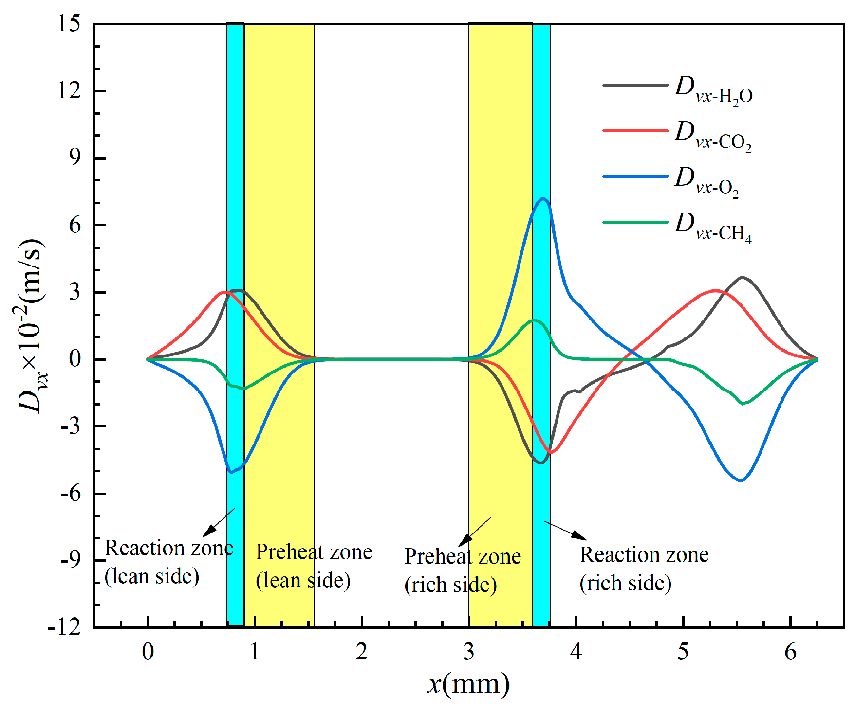
4.2.1. Effect of Preferential Diffusion

In this study, as the fuel of CH4 and operating pressure of atmosphere are settled, the consumption speed is mainly related to the fuel concentration and the temperature of the gas mixture. Hence, the reactant concentration and heat transfer in the preheat zone are discussed in Figure 10, Figure 11 and Figure 12. To quantify the effect of difference in a two-dimensional flow and mass diffusivities of species and radicals (described as preferential diffusion) on the distribution of the reactants, the local equivalence ratio is adopted as Equation (8). Barlow et al. [16] proposed it via calculating the local fuel/oxygen atom balance for major species (CH4, O2, H2O, CO2, CO, and H2).
ϕ local = 0.5 X H 2 + X H 2 O + X CO 2 + X CO + 2 X CH 4 0.5 X CO + X H 2 O + X O 2 + X CO 2
where Xi is the molar fraction of species i.
The local equivalence ratio, mass fraction, and diffusivities of major species in the preheat zone of the main flame are presented in Figure 10. The reference surface of T = 700 K is divided into rich side and lean side by the peak of flame. The concentration of the major species and ϕlocal is steady from the flame wing to flame tip, illustrating that the increase in Sc (in Figure 8) from the flame wing to tip exhibits little correlation with species concentration. However, the YH2O, YCO2 decrease and YO2, YCH4 increase rapidly from flame root to flame wing; moreover, the growing ϕlocal contributes to the increase in Sc. The mass fractions of O2 and CH4 on the rich side are higher than those of the lean side, while the mass fractions of H2O and CO2 on the rich side are lower than those of the lean side. The mass fraction of CO on the rich side is nearly equal to the lean side. The difference between the rich and lean sides becomes weaker from the flame root to the tip, which is in accordance with the distribution of Sc present in Figure 8. Consider the variation of mass fraction of CH4, O2, H2O, and CO2 from the flame root to the tip; the diffusivities are discussed in Figure 10b. The diffusivity of H2O is dramatically larger than that of the CO2, which is produced in the reaction zone and diffused to the preheat zone. Moreover, the diffusivity of CH4 is greater than that of O2, which diffuses from the preheat zone to the reaction zone.
To reveal the effects of preferential diffusion on the main flame through the flame root, the diffusion velocity in the x-direction on section of y = 0.5 mm is presented in Figure 11. As can be seen, the H2O and CO2 diffuse from the production zone to the preheat zone, while CH4 and O2 diffuse from the preheat zone to the production zone both on the lean and the rich sides of the main flame. It is important to note that the Dvx of the considered species on the rich side is obviously higher than that on the lean side, and reaches peak value in the reaction zone. The diffusion difference of species between the rich and the lean sides of the main flame results in the species concentration distribution in the preheat zone, shown in Figure 10a.

4.2.2. Effect of Heat Transfer
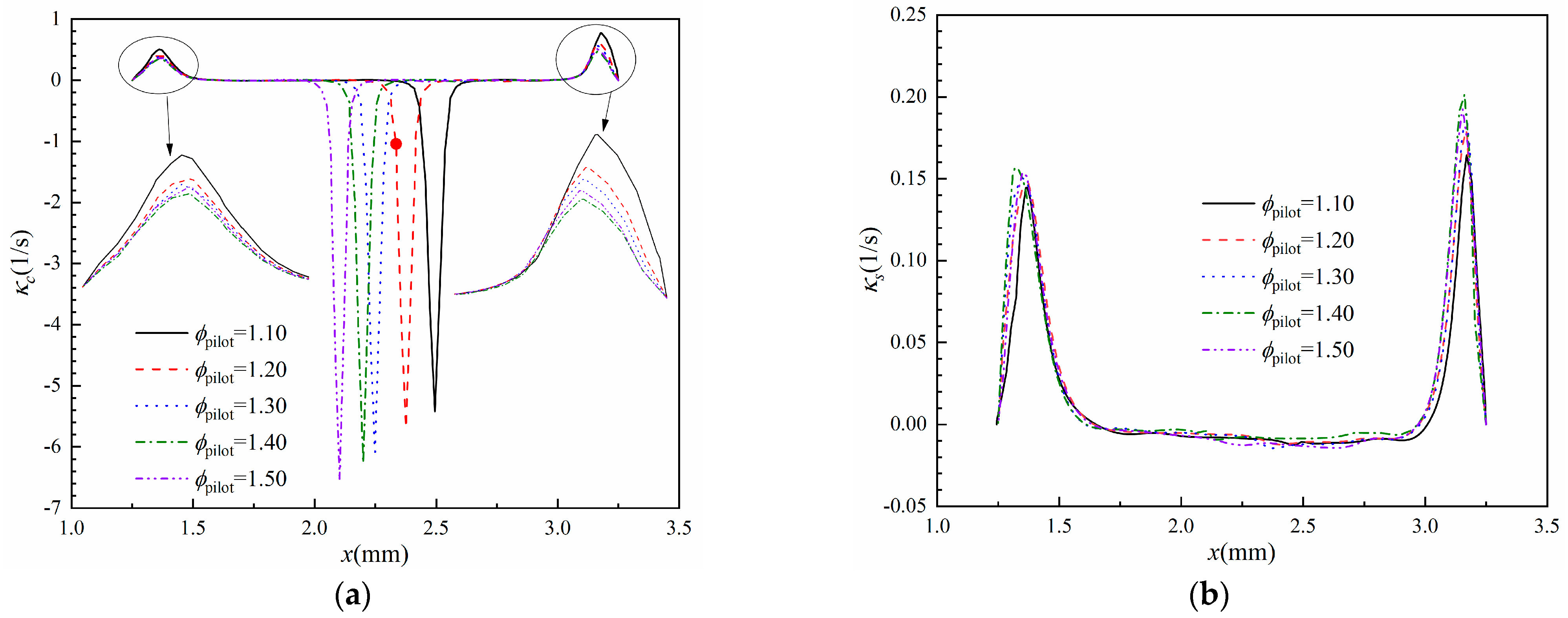
As can be seen in the contour of temperature shown in Figure 5a, the temperature of the rich pilot flame tip and the lean main flame tip are, respectively, 1900 K and 1800 K. Accordingly, the temperature of production zone on the rich side is also higher than that of the production zone on the lean side. The higher reactant concentrate of the rich pilot flame causes more heat release.
The temperature gradient in the x-direction and the thermal conductivity can express the heat transfer within and between the flames. To analyze the effect of heat transfer on the main flame, Figure 12 shows the distribution of dT/dx and λ on sections of y = 1, 2, and 3 mm. The maximum value of dT/dx is located near the inner boundary of the flame reaction zone. The maximum value of dT/dx on the rich side is larger than that of the lean side, while this difference decreases as the y-coordinate increases. The values of dT/dx and λ on the intersection points of T = 700 K reference line and three y-cross section lines are marked in the figures. Significantly, these values on the rich side are greater than those on the lean side. In conclusion, the conductive heat flux in the preheat and reaction zones of the rich side is greater than that of the lean side, and the difference decreases gradually from the flame root to the flame tip.

4.3. Flame Stretch

The flame stretch is mainly related to the flow motion, flame curvature, and local nonuniformity. According to Figure 8, the entire laminar premixed flame surface is smooth and planar. Hence, the weak stretch effect on the local flame speed can be expressed as
S u = S u 0 L κ
where Su0 is the unstretched flame speed; L is the Markstein length, which is related to the order of the flame thickness and the properties of gas mixtures [26]; κ is the flame stretch rate given by
κ = κ s + κ c
where κs and κc are, respectively, strain rate and curvature rate. The strain rate results from the flow strain which is related to the velocity field, and it consists of the shear strain rate κs,s and normal strain rate κs,n,
κ s , s = n y n x u x + v y
κ s , n = n y 2 u y n x 2 v x
where u and v are y-component and x-component velocity, respectively, and n is the normal of the flame front towards the reactants. Meanwhile, the curvature rate, κc, caused by the flame curvature, can be calculated as [27]
κ c = u n y + v n x d n y d y + d n x d x
Considering the flow nonuniformity along the normal direction of the flame surface, a reference surface is chosen by 99% of maximum methane mass fraction for the calculation of the stretch rate [28]. The profiles of κ, κc, κs, κs,s, and κs,n (Equations (10)–(13)) along the reference surface in the x-direction are presented in Figure 13. The positive peak values of the stretch rate are observed near the flame base, with κ = 0.81 × 10⁴ 1/s on the rich side and κ = 0.57 × 10⁴ 1/s on the lean side, illustrating that the stretch rate on the flame base of the rich side is greater than that of the lean side. Both the values of κc and κs on the rich side are greater than those of the lean side, while the κc plays a more important role. The curves of κs,s and κs almost coincide, proving that the κs is dominated by the shear strain rate and the normal strain rate κs,n is negligible. Moreover, the negative peak values of the κ and κc are near the flame tip, where |κs| << |κc|. Accordingly, the stretch rate on the flame tip is mainly dominated by the curvature rate. Thus, the quantity of the stretch rate is negative near the flame tip, while it is positive near the flame root. The negative stretch rate will increase the reaction rate and heat generation, which contributes to increasing the local flame speed. The positive stretch rate has the opposite effects.
The effects of ϕpilot on the flame stretch are shown in Figure 14. According to the above analysis, the stretch rate near the flame tip is mainly dominated by the curvature rate, while it is related to both the curvature rate and strain rate near the flame root. From Figure 14a, as the ϕpilot increases from 1.10 to 1.50, the peak value of |κc| (near the flame tip) increases by 21%, and its location moves towards the lean main flame. The increase in the pilot flame equivalence ratio promotes the curvature of the flame tip; meanwhile, the displacement of the peak stretch rate contributes to the reduction in the flame tip deflection, shown in Figure 6a. And from the enlarged curves in Figure 14a,b, the values of |κc| and |κs| near the flame root on the rich side are generally greater than those on the lean side under conditions of various ϕpilot. Hence, the curvature rate and strain rate show more significant effects on the rich side of the main flame root. As the ϕpilot increases from 1.10 to 1.40, and then to 1.5, the κc (near the flame root) first decreases dramatically and then increases slightly; meanwhile, the location of the peak value moves towards the center of the main flame, whereas the κs increases and then decreases as the ϕpilot increases from 1.10 to 1.40, and then to 1.5. The displacement of the peak κc and κs towards the main flame near the flame root on the rich sides coincides with the profile of the flame root with different ϕpilot, shown in Figure 6a.
The effect of vpilot on the flame stretch is shown in Figure 15. As the vpilot increases from 1.10 to 1.50, the peak value of |κc| (near the flame tip) increases by 34%, and its location moves towards the lean main flame. Similarly, the increase in pilot flame inlet velocity promotes the curvature of the flame tip and contributes to the reduction in the flame tip deflection. Considering the stretch rate near the flame root, the κc and κs increase in a reducing rate as the vpilot increases from 0.5 m/s to 0.9 m/s. Meanwhile, both the κc and κs near the flame root on the rich side are generally greater than those on the lean side under conditions of various vpilot. The locations of peak κc and κs (near the flame root) on the rich side move towards the center of the main flame, which contributes to the profile of the flame root, shown in Figure 7a.

5. Conclusions

A numerical investigation was conducted in this paper to analyze the effect of a laminar rich pilot methane/air jet flame on the flame structure and burning speed of a lean main flame. Accordingly, the flame characteristics on the rich and lean sides of the main flame were highlighted, considering the influence of preferential diffusion, heat transfer, and flame stretch. The main conclusions are as follows.
(1)
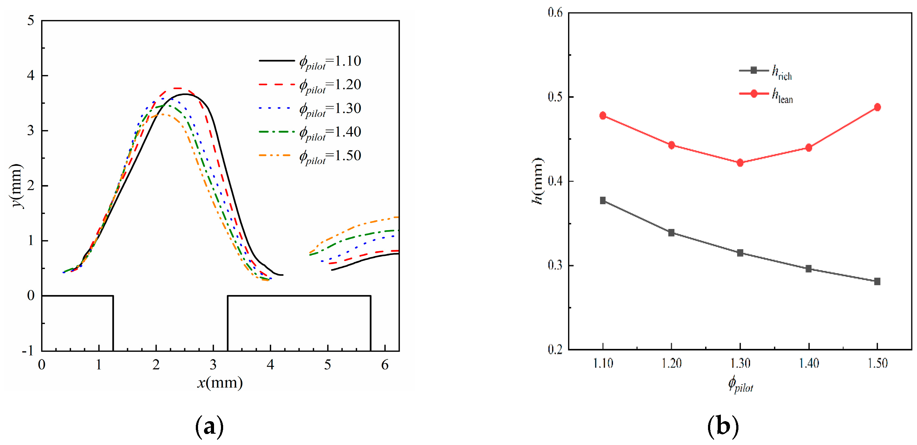
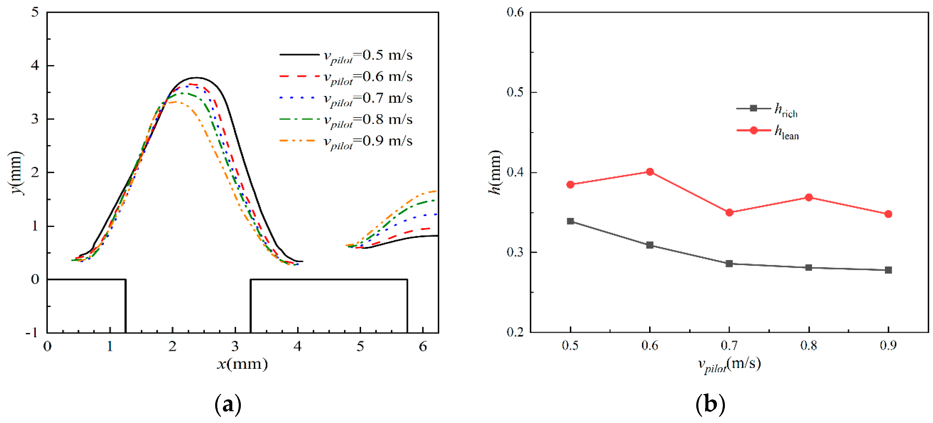
The main flame is asymmetrical, with the flame tip inclining toward the pilot flame. Meanwhile, the main flame stand-off distances of the lean side are larger than those of the rich side. The pilot flame could help the main flame anchor closer to the flame wall, and this influence is more remarkable as the ϕpilot and vpilot increase.
(2)
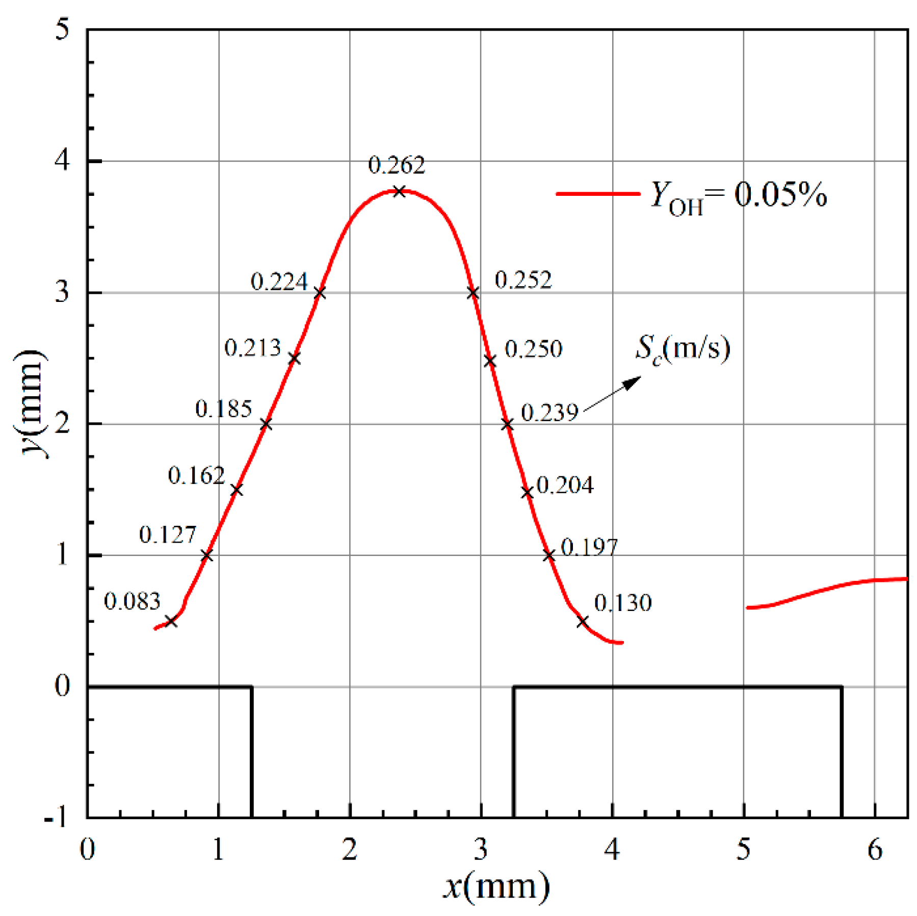
Affected by the pilot flame, the combustion speeds on the rich side are generally greater than those on the lean side. The increasing ϕpilot and vpilot promote the combustion on the rich side of the main flame root, and this effect becomes weaker gradually as ϕpilot increases from 1.1 to 1.5 and vpilot increases from 0.5 m/s to 0.9 m/s.
(3)
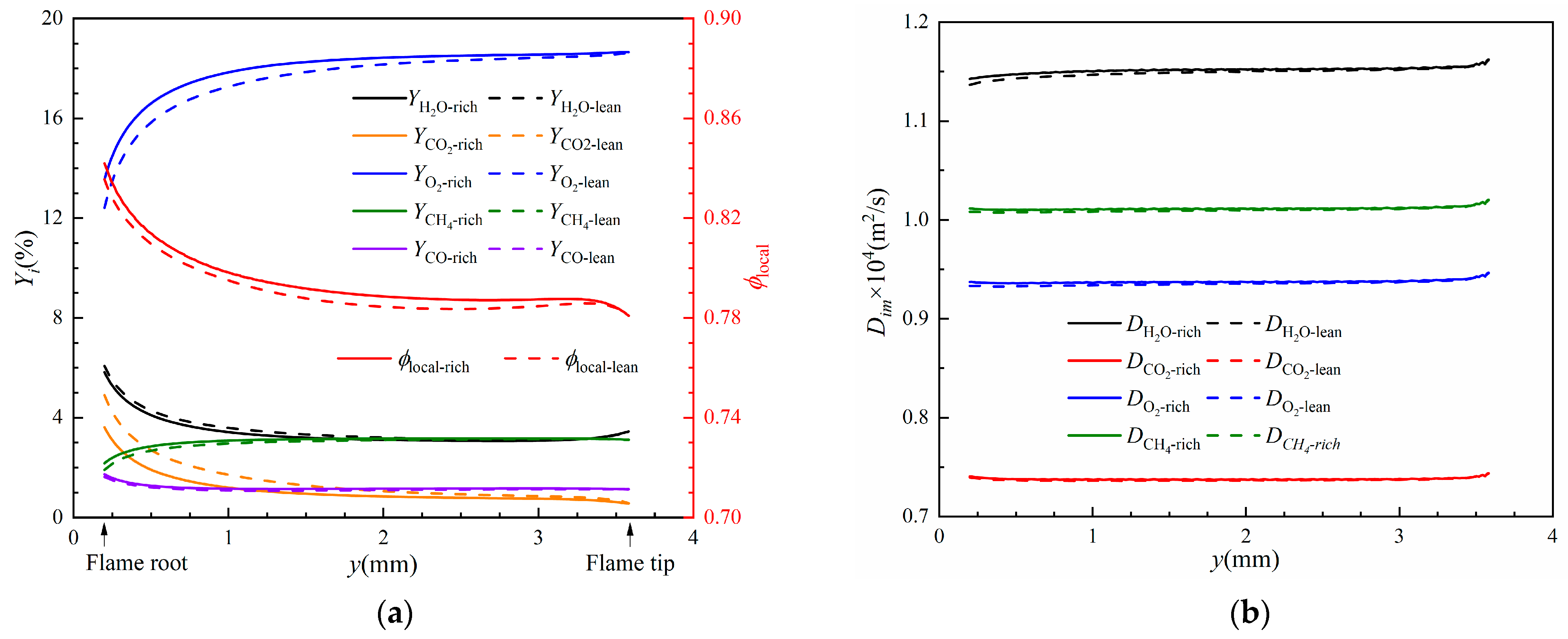
The local equivalence ratio on the main flame preheat zone of the rich side is generally greater than that of the lean side. Meanwhile, the conductive heat flux on the preheat and reaction zones of the rich side is greater than that of the lean side. The distribution of the local equivalence ratio and heat transfer contribute to the increase in combustion speeds on the rich side of the main flame.
(4)
The flame stretch rate near the flame tip is negative and dominated by the curvature rate, while it is positive and related to both the curvature rate and strain rate near the flame root. Both the curvature and strain rate show more significant effects on the rich side of the main flame root, which contributes to the main flame bending towards the pilot flame.

Author Contributions

Conceptualization, L.Z. and Y.C.; methodology, Y.C. and L.Z.; software, L.Z. and P.Y.; validation, L.Z. and P.Y.; data curation, L.Z. and W.M.; writing—original draft preparation, L.Z.; writing—review and editing, L.Z., W.M., and P.Z.; funding acquisition, L.Z. All authors have read and agreed to the published version of the manuscript.

Funding

This research was funded by the Shandong Provincial Natural Science Foundation of China, grant numbers ZR2021QE273.

Data Availability Statement

Datasets are available upon reasonable request.

Conflicts of Interest

Author Wenlong Mao was employed by the company Shandong Special Equipment Inspection Institute Group Co., Ltd. The remaining authors declare that the research was conducted in the absence of any commercial or financial relationships that could be construed as a potential conflict of interest.

Nomenclature

CpSpecific heat capacity (J/(kg·K))
dWidth of flame port (mm)
DDiffusion coefficient (m2/s)
DvDiffusion velocity (m/s)
HFlame height (mm)
hStand-off distance (mm)
pPressure (Pa)
riEnthalpy of species i
ScConsumption speed (m/s)
TTemperature (K)
uVelocity in x-direction (m/s)
vVelocity in y-direction (m/s)
WMolar mass (g/mol)
xx-coordinate (m)
yy-coordinate (m)
XiMolar fraction of the ith species
YiMass fraction of the ith species
Greek symbols
ρDensity (kg/m3)
ϕEquivalence ratio
ν ˙ i Molar production rate of species i
ωVolumetric heat release rate (W/m3)
λThermal conductivity (W/(m·K))
κFlame stretch rate (1/s)
Subscripts
mainMain flame
pilotPilot flame
leanLean side of main flame
richRich side of main flame
bBurned mixture
uUnburned mixture

References

  1. Altay, H.M.; Kedia, K.S.; Speth, R.L.; Ghoniem, A.F. Two-dimensional simulations of steady perforated-plate stabilized premixed flames. Combust. Theory Model. 2010, 14, 125–154. [Google Scholar] [CrossRef]
  2. Kedia, K.S.; Ghoniem, A.F. Mechanisms of stabilization and blowoff of a premixed flame downstream of a heat-conducting perforated plate. Combust. Flame 2012, 159, 1055–1069. [Google Scholar] [CrossRef]
  3. Qin, F.; Shah, A.; Huang, Z.W.; Peng, L.N.; Tunestal, P.; Bai, X.S. Detailed numerical simulation of transient mixing and combustion of premixed methane/air mixtures in a pre-chamber/main-chamber system relevant to internal combustion engines. Combust. Flame 2018, 188, 357–366. [Google Scholar] [CrossRef]
  4. Yasuda, H.; Asato, K.; Miyasaka, T.; Miyashita, T.; Sakakibara, D.; Kurachi, S.; Hagi, S.; Umeda, Y. Characteristics of Combustion of Rich-Lean Burner Controlled Boundary Region between Rich and Lean Flames. Trans. Jpn. Soc. Mech. Eng. B 2006, 73, 3143–3150. [Google Scholar]
  5. Aoki, S.; Yamazaki, H. Combustion Mechanism of Rich-Lean Flame Burner Controlled Boundary Zone. In Proceedings of the ASME/JSME Thermal Engineering Heat Transfer Summer Conference collocated with the ASME 2007 InterPACK Conference, Vancouver, BC, Canada, 8–12 July 2007. [Google Scholar]
  6. Vance, F.H.; Shoshin, Y.; Goey, L.; Oijen, J. An investigation into flashback and blow-off for premixed flames stabilized without a recirculation vortex. Combust. Flame 2021, 235, 111690. [Google Scholar] [CrossRef]
  7. Yu, S.; Bai, X.S.; Zhou, B.; Wang, Z.; Aldén, M. Numerical Studies of the Pilot Flame Effect on a Piloted Jet Flame. Combust. Sci. Technol. 2019, 194, 351–364. [Google Scholar] [CrossRef]
  8. Zhou, B.; Brackmann, C.; Li, Z.; Aldén, M.; Bai, X.S. Simultaneous multi-species and temperature visualization of premixed flames in the distributed reaction zone regime. Proc. Combust. Inst. 2015, 35, 1409–1416. [Google Scholar] [CrossRef]
  9. Pires, J.M.; Fernandes, E.C. Combined effect of equivalence ratio and velocity gradients on flame stability and emission formation. Fuel 2018, 222, 800–809. [Google Scholar] [CrossRef]
  10. Li, Z.S.; Li, B.; Sun, Z.W.; Bai, X.S.; Aldén, M. Turbulence and combustion interaction: High resolution local flame front structure visualization using simultaneous single-shot PLIF imaging of CH, OH, and CH2O in a piloted premixed jet flame. Combust. Flame 2010, 157, 1087–1096. [Google Scholar] [CrossRef]
  11. Zhou, B.; Costa, M.; Li, Z.; Aldén, M.; Bai, X.S. Characterization of the reaction zone structures in a laboratory combustor using optical diagnostics: From flame to flameless combustion. Proc. Combust. Inst. 2016, 36, 4305–4312. [Google Scholar] [CrossRef]
  12. Zhou, B.; Brackmann, C.; Wang, Z.; Li, Z.; Richter, M.; Alden, M.; Bai, X.S. Thin reaction zone and distributed reaction zone regimes in turbulent premixed methane/air flames: Scalar distributions and correlations. Combust. Flame 2017, 175, 220–236. [Google Scholar] [CrossRef]
  13. Lúcio, T.; Fernandes, E. Rich–Lean Flame Interaction in a Lamella-Type Burner. Combust. Sci. Technol. 2015, 188, 416–438. [Google Scholar] [CrossRef]
  14. Guo, H.; Liu, F.; Smallwood, G.J. A numerical study of laminar methane/air triple flames in two-dimensional mixing layers. Int. J. Therm. Sci. 2006, 45, 586–594. [Google Scholar] [CrossRef]
  15. Azzoni, R.; Ratti, S.; Puri, I.K.; Aggarwal, S.K. The structure of triple flames stabilized on slot burner. Combust. Flame 1999, 119, 23–40. [Google Scholar] [CrossRef]
  16. Barlow, R.S.; Dunn, M.J.; Sweeney, M.S.; Hochgreb, S. Effects of preferential transport in turbulent bluff-body-stabilized lean premixed CH4/air flames. Combust. Flame 2012, 159, 2563–2575. [Google Scholar] [CrossRef]
  17. Wan, J.; Zhao, H.; Akkerman, V.Y. Anchoring mechanisms of a holder-stabilized premixed flame in a preheated mesoscale combustor. Phys. Fluids 2020, 32, 97103. [Google Scholar] [CrossRef]
  18. Vance, F.H.; Shoshin, Y.; de Goey, L.P.H.; van Oijen, J.A. Quantifying the impact of heat loss, stretch and preferential diffusion effects to the anchoring of bluff body stabilized premixed flames. Combust. Flame 2022, 237, 111729. [Google Scholar] [CrossRef]
  19. Choi, C.W.; Puri, I.K. Flame stretch effects on partially premixed flames. Combust. Flame 2000, 123, 119–139. [Google Scholar] [CrossRef]
  20. Choi, C.W.; Puri, I.K. Contribution of curvature to flame-stretch effects on premixed flames. Combust. Flame 2001, 126, 1640–1654. [Google Scholar] [CrossRef]
  21. Michaels, D.; Ghoniem, A.F. Impact of the bluff-body material on the flame leading edge structure and flame–flow interaction of premixed CH4/air flames. Combust. Flame 2016, 172, 62–78. [Google Scholar] [CrossRef]
  22. Bennett, B.A.V.; Fielding, J.; Mauro, R.J.; Long, M.B.; Smooke, M.D. A comparison of the structures of lean and rich axisymmetric laminar Bunsen flames: Application of local rectangular refinement solution-adaptive gridding. Combust. Theory Model. 1999, 3, 657–687. [Google Scholar] [CrossRef]
  23. Smooke, M.D.; Puri, I.K.; Seshadri, K. A comparison between numerical calculations and experimental measurements of the structure of a counterflow diffusion flame burning diluted methane in diluted air. Symp. (Int.) Combust. 1988, 21, 1783–1792. [Google Scholar] [CrossRef]
  24. Kedia, K.S. Development of a Multi-Scale Projection Method with Immersed Boundaries for Chemically Reactive Flows and Its Application to Examine Flame Stabilization and Blow-Off Mechanisms. Ph.D. Thesis, Massachusetts Institute of Technology, Cambridge, MA, USA, 2013. [Google Scholar]
  25. Hu, S.; Gao, J.; Gong, C.; Zhou, Y.; Bai, X.S.; Li, Z.S.; Alden, M. Assessment of uncertainties of laminar flame speed of premixed flames as determined using a Bunsen burner at varying pressures. Appl. Energy 2017, 227, 149–158. [Google Scholar] [CrossRef]
  26. Bechtold, J.K.; Matalon, M. The dependence of the Markstein length on stoichiometry. Combust. Flame 2001, 127, 1906–1913. [Google Scholar] [CrossRef]
  27. Kedia, K.S.; Ghoniem, A.F. The blow-off mechanism of a bluff-body stabilized laminar premixed flame. Combust. Flame 2015, 162, 1304–1315. [Google Scholar] [CrossRef]
  28. Chen, T.; Yu, S.; Liu, Y.C. Effects of pressure on propagation characteristics of methane-air edge flames within two-dimensional mixing layers: A numerical study. Fuel 2021, 301, 120857. [Google Scholar] [CrossRef]
Figure 1. Schematic view of burner and the schematic diagram of the numerical model.
Energies 17 03430 g001
Figure 2. Profiles of flame temperature with different grid quantity.
Energies 17 03430 g002
Figure 3. Schematic diagram of experimental system.
Energies 17 03430 g003
Figure 4. Spatial distribution of normalized OH PLIF signal intensity and numerical OH mass fraction.
Energies 17 03430 g004
Figure 5. Contours of T and ω at ϕmain = 0.8, vmain = 1 m/s, ϕpilot = 1.2, and vpilot = 0.5 m/s. (a) Temperature; (b) volumetric heat release rate.
Energies 17 03430 g005
Figure 6. Profile of flame position and stand-off distance on the rich and lean side of the main flame with different pilot flame equivalence ratio at ϕmain = 0.8 and vmain = 1 m/s. (a) Flame position; (b) stand-off distance.
Energies 17 03430 g006
Figure 7. Profile of flame position and stand-off distance on the rich and lean side of the main flame with different pilot flame inlet velocity at ϕmain = 0.8, vmain = 1 m/s, and ϕpilot = 1.2. (a) Flame position; (b) stand-off distance.
Energies 17 03430 g007
Figure 8. Distribution of the consumption speed on the flame surface, at ϕpilot = 1.2, vpilot = 0.5 m/s, ϕmain = 0.8, and vmain = 1 m/s.
Energies 17 03430 g008
Figure 9. The Sc on the lean and rich sides of the main flame root (y = 0.5 mm) with different pilot flame equivalence ratio and inlet velocity at ϕmain = 0.8 and vmain = 1 m/s. (a) With different ϕpilot; (b) with different vpilot.
Energies 17 03430 g009
Figure 10. Distribution of local equivalence ratio, mass fraction, and diffusivities of major species on the surface of T = 700 K at ϕmain = 0.8, vmain = 1 m/s, ϕpilot = 1.2, and vpilot = 0.5 m/s. (a) Local equivalence ratio and mass fraction; (b) diffusivity.
Energies 17 03430 g010
Figure 11. Diffusion velocity in x-direction at y = 0.5 mm.
Energies 17 03430 g011
Figure 12. Distribution of temperature gradient in x-direction and thermal conductivity at y = 1 mm, 2 mm, and 3 mm. (a) Temperature gradient; (b) thermal conductivity.
Energies 17 03430 g012
Figure 13. Profile of flame stretch rate at ϕmain = 0.8, vmain = 1.0 m/s, ϕpilot = 1.2, and vpilot = 0.5 m/s.
Energies 17 03430 g013
Figure 14. Profile of flame stretch rate with different pilot flame equivalence ratios at ϕmain = 0.8, vmain = 1.0 m/s, and vpilot = 0.5 m/s. (a) κc; (b) κs.
Energies 17 03430 g014
Figure 15. Profile of flame stretch rate with different pilot flame inlet velocity at ϕmain = 0.8, vmain = 1.0 m/s, and vpilot = 0.5 m/s. (a) κc; (b) κs.
Energies 17 03430 g015
Disclaimer/Publisher’s Note: The statements, opinions and data contained in all publications are solely those of the individual author(s) and contributor(s) and not of MDPI and/or the editor(s). MDPI and/or the editor(s) disclaim responsibility for any injury to people or property resulting from any ideas, methods, instructions or products referred to in the content.

