Abstract
This paper proposes a new technique for a single-direction solar tracker. The proposed design is based on a sun sensor system that controls the position of the solar panel. The sun sensors of the proposed design contain four photodiodes that are placed on the solar panel in specific angles and directions. The proposed system has several advantages such as the simplicity of implementing the system. This system combines the real-time tracking of sunlight and the low cost of applying a single-direction tracker. The prototyping experiment and Simulink MATLAB were applied to show the advantages of applying a single-direction tracker by following the angle of sunlight during the day. Real-time sun position and irradiation data were applied. The experimental results show that the proposed single-axis sun sensor PV tracker system generates around 20 more electric power than a fixed-structure PV system.
1. Introduction
Due to the expansion of global warming caused by high energy consumption, it has become essential to replace conventional energy sources with green and clean energy sources, such as renewable energy sources [1,2,3,4,5]. As of late, renewable energy resources have received a lot of attention from governments, companies, and researchers, which has led to improving the performance of renewable energy applications. Renewable energy accounted for 11.9% of primary global energy in 2021 [1]. This has also led to specially designed machines used for mobility [6,7], with the reliability of the machines being especially important to ensure human safety [8]. Investment in renewable energy resources and applications has grown rapidly, especially in the solar energy sector. As a comparison of increasing investment in the installation of photovoltaic (PV) systems, the capacity of photovoltaic installations during 2012 was 100 GW while the number of PV installations reached 1 TW during 2021. Moreover, there is a global goal of increasing the capacity of photovoltaic installations to 75 TW by 2050 [1].
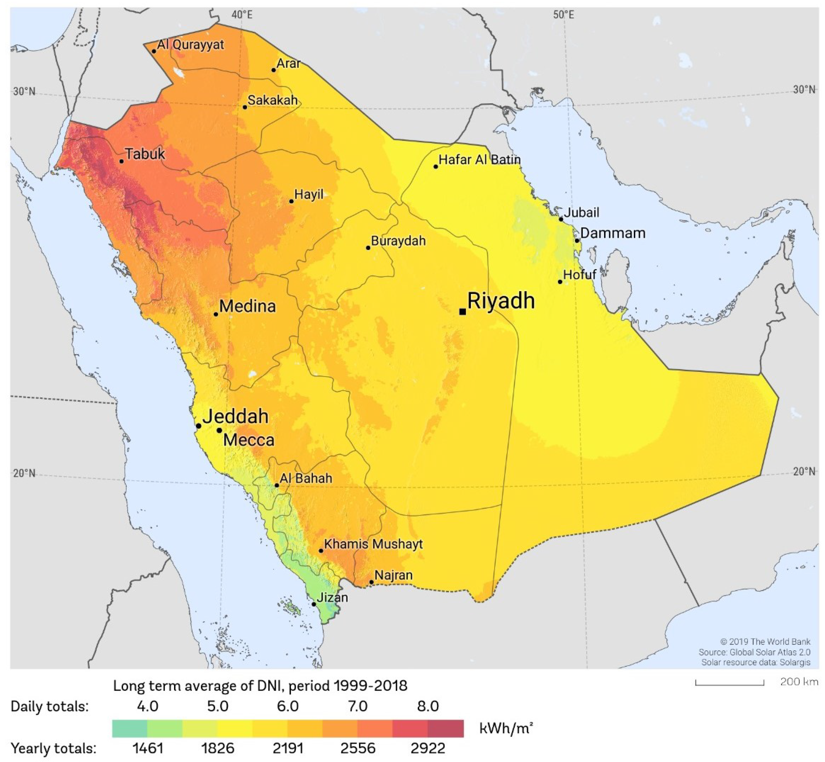
Saudi Arabia has begun investing in applications of several renewable energy resources. However, most of the renewable energy application investment is in photovoltaic systems [3]. Saudi Arabia is located in the sunbelt, which makes it geographically suitable for solar energy generation. Moreover, because of the location advantages of Saudi Arabia, the average daily intensity of direct solar radiation received in most of the Saudi Arabian region lies between 8 kWh/m2 (Tabuk) and 5 kWh/m2 (Riyadh), as shown in Figure 1 [3]. Therefore, sources of renewable energy, especially solar energy, are attractive for study, with the aim of developing the technology and improving the performance of solar energy applications. One of the main technologies that can improve the efficiency of sunlight energy applications is the tracking system.
Sunlight tracker technology can address the drawbacks of fixed-structure photovoltaic systems. One of the main drawbacks of fixed-structure photovoltaic systems is the decrease in electricity energy produced. This decrease in electricity production is caused by changes in the angle of the Sun. Therefore, the sunlight tracker can raise the output of the photovoltaic system by minimizing the difference in the incident angle between the sunlight and the solar panel [2,9,10,11,12,13,14,15,16,17,18]. Solar tracking systems can be achieved by two different general methods: single-direction tracking systems and dual-direction tracking systems. A single-direction PV tracker has one degree of freedom, which acts as a rotation axis. The PV surface is rotated along an extended axis either from the east to the west direction or from the north to the south direction while the slope of the surface is fixed. A single-direction PV tracking system can enhance the output electrical energy of the photovoltaic over the fixed-structure PV system; in fact, many researchers have applied various technologies of PV tracking systems to improve the efficiency of power generation in PV systems [2,9,19]. In [1,10], the experimental study and results of a tracking system with one axis and a double-axis PV tracker show that a power gain of 37.53% was achieved via implementing a single-axis tracker over a fixed-structure PV system. Also, the power gain of the dual-axis PV tracker system over the fixed-structure PV system was 43.87%. Therefore, both PV tracker systems can improve the generated power output from the PV system over a fixed structure.
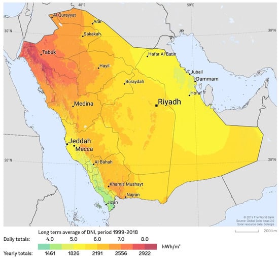
Figure 1.
Solar radiation of Saudi Arabia [20,21].
Figure 1.
Solar radiation of Saudi Arabia [20,21].
However, the single-axis PV tracker system has many advantages over the dual-axis PV tracker system, such as the cost, complexity, control, and maintenance. Hence, the focus of this paper is to improve the design of a single-direction PV tracker. The proposed design of a single-direction PV tracker contains four photodiodes that act as a sun sensor to measure the angle of the sunlight. By measuring the angle between the sunlight and the photodiode sun sensors, the PV panel rotates until the sun sensors have the optimal angle to the sunlight. This design of a single-axis PV tracking system has several advantages, such as the lower cost of using only four sun sensors, less complexity, and more accurate real-time tracking of sunlight.
Therefore, this paper contributes several unique insights to the subject area compared with other published material. Here are the key additions:
1.1. Simplicity and Cost-Effectiveness
The proposed design utilizes only four photodiodes to track the Sun, making it simpler and more cost-effective compared to more complex dual-axis tracking systems. This simplicity reduces the overall system cost and maintenance requirements.
1.2. Real-Time Tracking
The system is based on the real-time tracking of sunlight using an analog sun sensor system, which improves the accuracy of tracking the sun’s position throughout the day.
1.3. Prototyping and Simulation Validation
The design was validated both through prototyping and MATLAB Simulink simulations, demonstrating its practical feasibility and effectiveness in improving solar energy capture. The experimental results indicate that the system generates approximately 20% more electric power compared to a fixed-structure PV system.
1.4. Efficiency Comparison
The paper includes a comprehensive comparison with fixed-structure, single-axis, and dual-axis tracking systems, highlighting the proposed system’s balance between efficiency and cost. While dual-axis systems generate the highest energy, the proposed single-axis system offers a significant improvement over fixed systems with lower complexity and cost.
These contributions demonstrate how the proposed design advances the field by offering a practical, cost-effective, and efficient solution for solar tracking, making it accessible for broader applications, particularly in regions like Saudi Arabia with high solar irradiance.
2. Theory
2.1. Sun Movement
The Sun is the center of the solar system and our planet revolves around it in elliptical orbits. The Earth takes a year, which is 365 days, to encircle the Sun. The rotation of the planet around the Sun is not exactly always on the same track (axis) in all seasons. However, the Earth’s rotation has a slop that varies from to [19]. This variation in the slop’s angle causes the different seasons and weathers. Therefore, the orbit of the Earth to the Sun forms an angle position of the Sun’s equator, which is declination, and it can be represented as . The declination angle can be calculated with the Cooper equation as follows [10]:
where n is the days in a year in sequence number. The rotation of the Earth around the Sun shows the Sun’s motions in the sky from the east to west direction. Moreover, one full rotation of the Earth is equal to . Therefore, the Sun’s elevation angle is shifted by per hour. On the other hand, the Sun’s azimuth angle is shifted by per month [10].
2.2. Sun Energy
During the day, the Sun generates solar radiation that is delivered to the surface of the Earth. By using photovoltaic technology, the delivered sunlight radiation can be used to generate electrical energy. Figure 2 explains the difference between the sunlight direction and the photovoltaic direction, which is the incident angle. The incident angle is the difference between the sunlight angle to the surface of the photovoltaic angle, which can be represented by . With an increasing incident angle, the energy produced from the photovoltaic is reduced. Therefore, the photovoltaic electrical energy can be estimated by the next equation [10]:
where the energy produced by the photovoltaic is represented by P. The efficiency and the surface area of the photovoltaic are represented by and A, respectively. Also, I represents the sunlight radiation on the planet’s surface. The intensity of sunlight radiation on the planet’s surface varies based on the location of the planet’s surface as a result of several factors, where the unit of the solar radiation is W/m2.
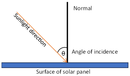
Figure 2.
The incident angle of sunlight.
Figure 3 illustrates a comparison of incident angle effects on photovoltaic energy. As a result, the produced energy of a photovoltaic is reduced when the incident angle increases. The largest energy loss of a photovoltaic occurs during sunrise and sunset. At sunrise and the sunset times, the incident angle of sunlight is more than . The lost energy of the photovoltaic based on the incident angle can be determined by the following equation [10,19]:
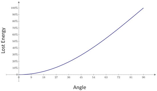
Figure 3.
The lost energy based on an incident angle.
3. System Design
3.1. Solar Tracking Technique
The proposed sunlight tracker is a single-direction tracker. The single-direction sunlight tracker uses sun sensor tracker technology. The sun sensor tracker technology can be used with photodiode sensors. The photodiode sensor tracker contains four photodiodes around the solar panel (photovoltaic) frame. Figure 4 shows the four photodiodes sensors of the solar panel. The proposed solar tracker system also contains a motor to rotate and move the solar panel from the east direction to the west direction during the day, while the direction of the motor is changed from west to east at the beginning of the day.
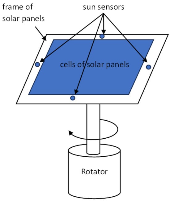
Figure 4.
Mechanical design of sun sensor solar tracking system.
3.2. Design of Sun Sensor System
The sun sensor system has two types of sunlight detector. An analog sun sensor is the first type in the sun sensor system, where the sunlight direction is measured by generating an output voltage. The generated voltage of the analog sensor is dependent on the condition of the sunlight strength. The other type of sun sensor is called a digital sensor. The digital sensor is based on generating digital data and it estimates the strength and angle of sunlight using the direction of the sunlight [9,10,22]. The analog sun sensor tracker system was applied in this research with four photodiodes. The four analog sun sensor photodiodes were constructed and arranged as follows: the top two photodiodes were in the cardinal directions, while the other two photodiodes were on the sides of the PV controlling the sunlight steering. This design of a sun sensor tracker system with a single-axis tracker has several advantages, such as real-time detection, the accuracy of tracking the sunlight direction, the lower cost of the solar tracker system, its ease of implementation, and its application in different arrangements of the solar panel array system. Figure 5 shows the configuration of sun sensor photodiodes in the PV tracker. The solar panel direction can be monitored based on the output voltages of the four photodiode sensors. The top photodiode sun sensor is bent to 30° facing the east direction. However, the bottom photodiode sun sensor is bent to 30° facing the west direction. The other two photodiode sun sensors are facing up at 0° to solar panel.
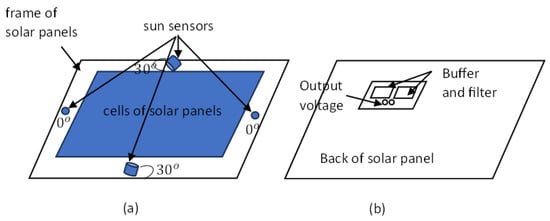
Figure 5.
Configuration of photodiodes in the sun sensor system. (a) The solar cell panel with sun sensors directions. (b) The back of solar panel with the electronic circuit sun sensor.
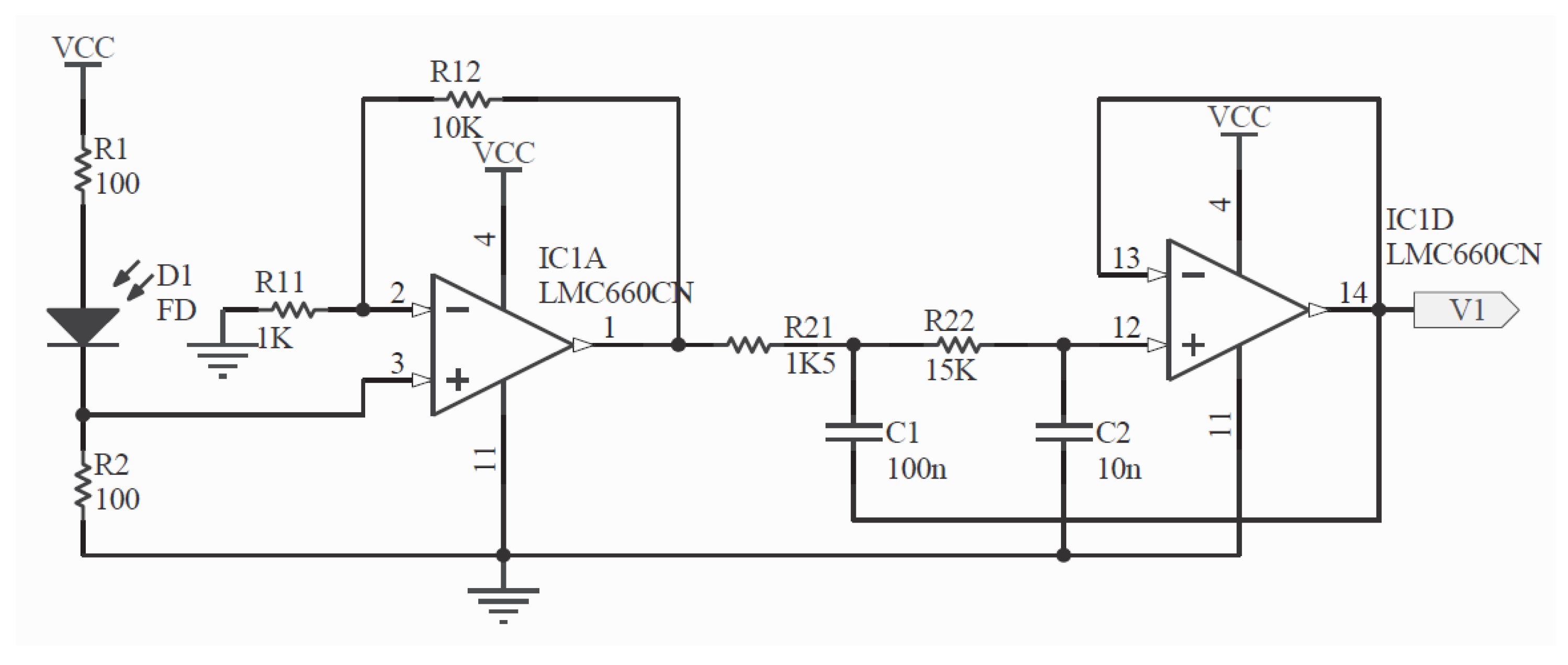
The principle work of this design is based on detecting the sunlight and then transferring the sunlight to current flow from the anode to cathode. When a high intensity of sunlight is received on an individual photodiode sun sensor, the flowing current that is generated in the photodiode is increased. With the increased flowing current in a specific photodiode sensor, the solar panel rotates until the side photodiode sun sensors have the most generated current. The generated currents from the photodiode sun sensors are converted to voltage using an electronic circuit. Figure 6 shows the electronic circuit of a photodiode sun sensor. This electronic circuit contains operational amplifiers that work as voltage buffers and low-pass filters. Hence, the generated voltage of this electronic circuit is in the range of 0–5 V.

Figure 6.
The electronic circuit of the sun sensor [10].
4. Limitations of Proposed Design
The proposed design is well suited for small-scale residential loads. However, it can be applied for larger load applications as a result of some conditions that are described below, such as the spacing between panels, complexity, and scalability of the design. For the tilt angles to adjust to seasonal variation, the proposed method follows a fixed-tilt angle by taking an average of the tilt angles needed for summers and winters in KSA. The fixed value of the tilt angle is taken as 68°, which is between 89° (summer) and 46° (winter) [23]. The limitations of the adopted methodology are stated below.
4.1. Spacing and Shading in Multi-Panel Systems
The proposed east–west rotation system requires adequate spacing between panels to avoid shading, which indeed uses more surface area. This can be a significant limitation in installations where surface area is at a premium, such as on rooftops or in densely packed solar farms. To mitigate this issue, the proposed system can be optimized by carefully designing the layout to minimize shading while maintaining optimal spacing.
4.2. Roof Installations
For rooftop installations, the space constraints are even more pronounced. To address this, the proposed system can be modified with customized mounts and brackets that allow for better space optimization. However, it is important to note that rooftop installations might still face challenges due to the fixed space and potential shading from other structures.
4.3. Performance in Winter and Low Solar Angles
The performance of the east–west rotation system may not be significantly improved during winter months when the solar angle is lower. In such cases, a north–south or up–down axis that allows the panels to tilt and follow the Sun’s inclination more effectively would indeed provide better performance. This system would ensure a more perpendicular angle of incidence, thereby enhancing energy capture.
4.4. Comparison with North–South-Axis Systems
The proposed system’s primary advantage is its simplicity and lower cost compared to dual-axis systems. However, a single-axis system that moves along the north–south axis (an up–down movement) could offer improved performance, particularly during the winter months. While the north–south axis system may require more complex control mechanisms and potentially higher costs, its performance benefits could outweigh these disadvantages in certain applications. An experimental evaluation comparing the proposed east–west rotation system with a north–south axis system showed that the latter could indeed offer better performance in terms of energy capture due to more optimal solar incidence angles throughout the year. However, the increased complexity and potential higher costs must be considered.
4.5. Cost and Complexity of Individual Motors
Implementing the proposed system in a multi-panel setup, where each panel requires an individual motor, can indeed be cost-prohibitive and complex. For instance, in a system with 12 panels, having 12 motors would significantly increase the cost and maintenance requirements. To address this, we suggest exploring centralized tracking mechanisms that can control multiple panels with fewer motors, reducing both complexity and costs.
5. Experimental Results
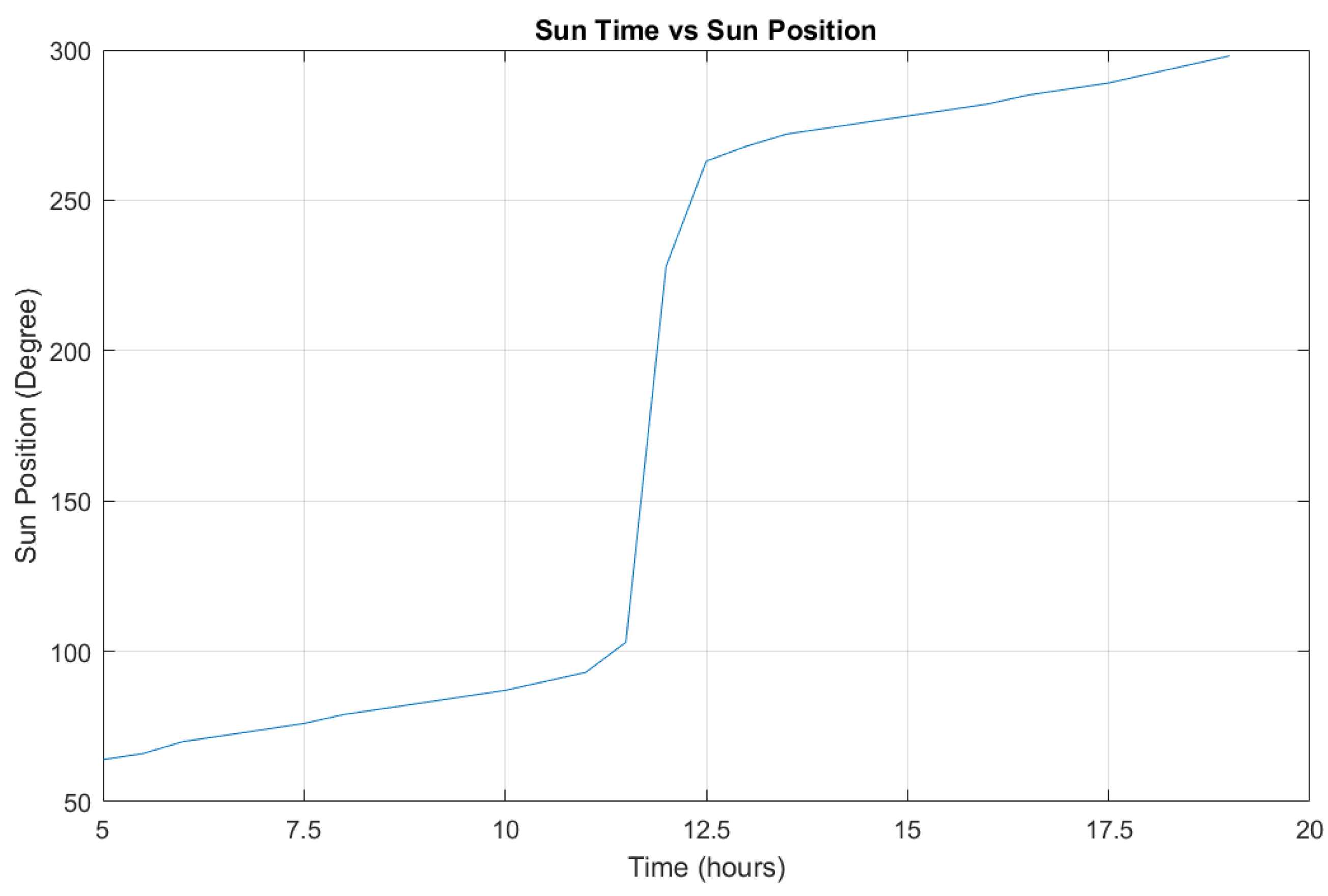
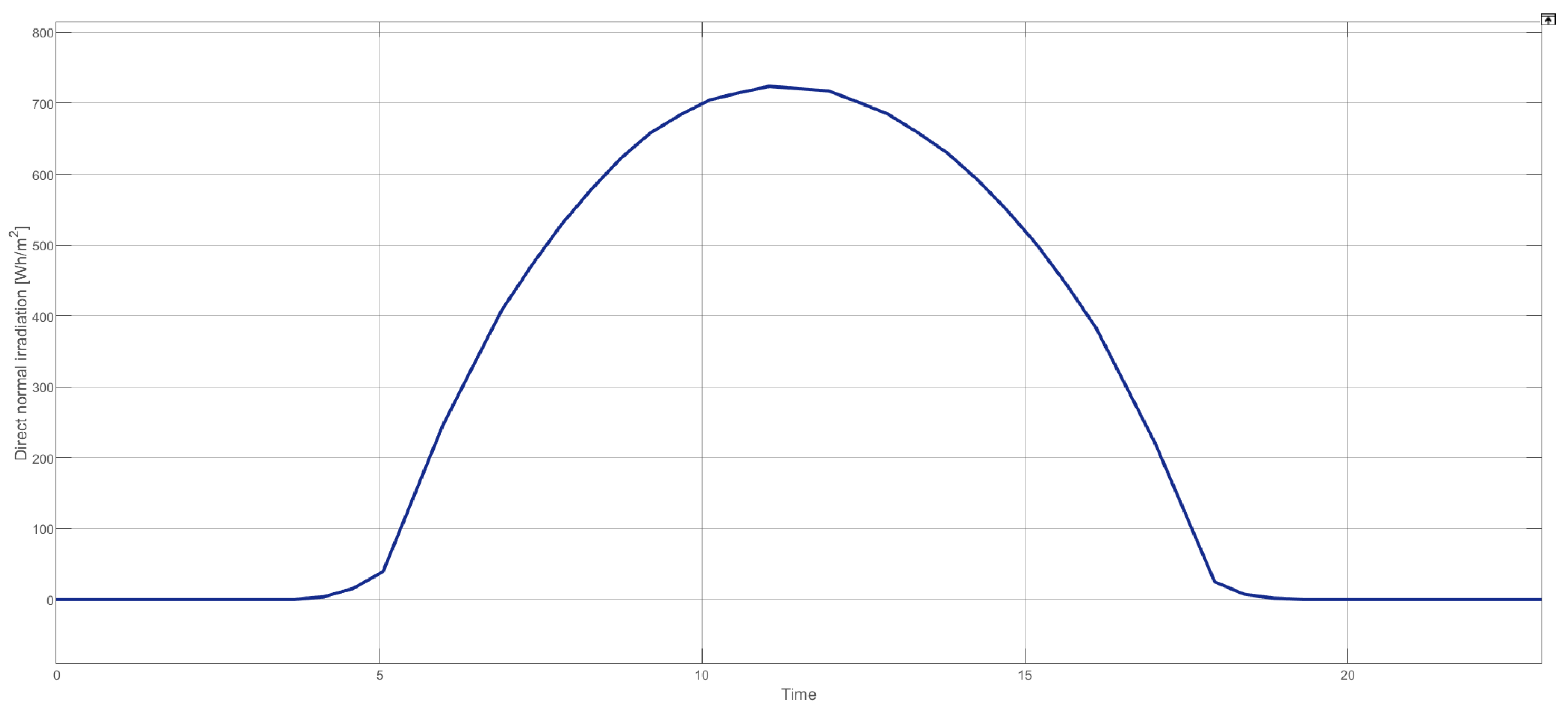
Tracking the solar energy of sunlight with a single-axis can be achieved by several methods, such as tracking the angle of sunlight. Tracking the sunlight angle could be achieved by applying a real experiment with a prototype and using MATLAB simulations. The proposed prototype of the single-axis PV solar tracker is shown in Figure 7. The proposed prototype contained a solar panel with 50 W output power, a DC servo motor, four photodiode sensors, a charger controller, and a controller (micro-controller) to control the DC motor. The other method of achieving the proposed design was applying it in a MATLAB simulation. By using MATLAB Simulink, the advantages of the sunlight angle tracker over the fixed solar panel were obviously shown. The real data of sunlight angles were implemented as shown in Figure 8, where the Sun rises from the northeast at 60° and sets in the northwest around 300°. The direct normal radiation of the sunlight in Saudi Arabia is presented in Figure 9, which shows the rich radiation of the Sun’s energy during an average day in June [20]. The fixed value of the tilt angle was taken as 68°, which was between 89° (summer) and 46o (winter) [23] for Riyadh city. The direct normal radiation of the sunlight in Saudi Arabia is presented in Figure 9, which shows the rich radiation of the Sun’s energy during an average day in June [20]. The graph shows the direct normal irradiation (Wh/m2) pattern against a typical winter day represented by time in hours along the horizontal axis. Sunrise occurs around 5 AM in the morning with a solar elevation angle of 10° [24]. The solar panels in this instance need to be oriented at an angle of 30° to achieve maximum energy harnessing. The north–south panel angle was fixed at a value of 68°, since the proposed method offers only single-axis movement (east–west).
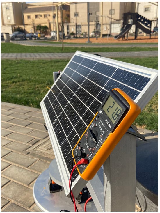
Figure 7.
Experiments with the proposed design of a single-axis sun sensor PV tracker system.
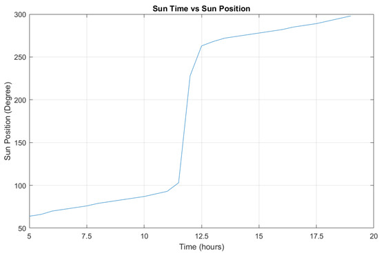
Figure 8.
The position of sunlight versus the sun time.
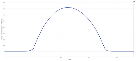
Figure 9.
The direct normal irradiation of Riyadh city during a day.
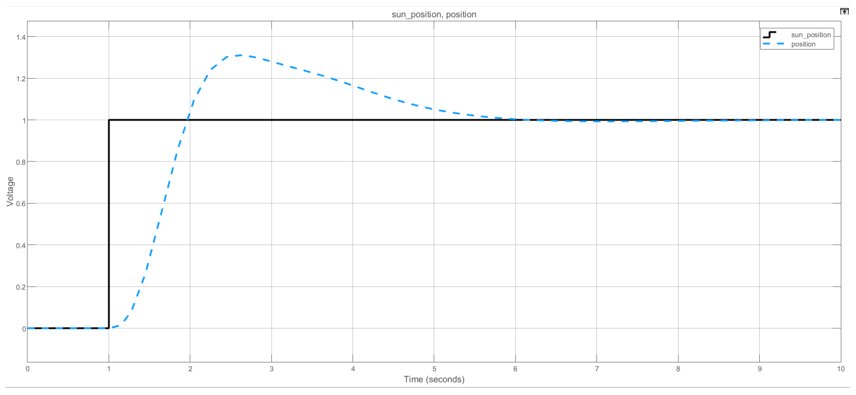
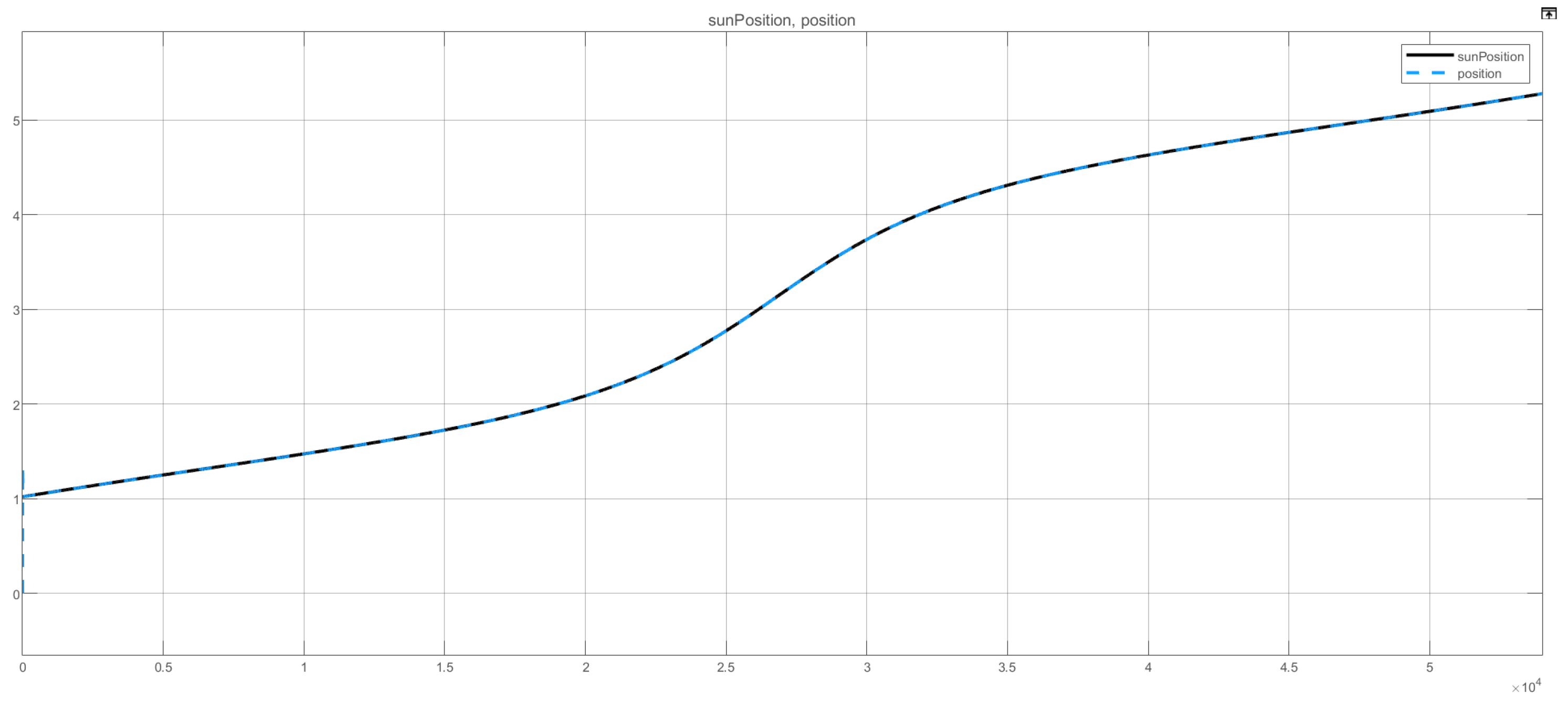
The motor motion based on the sunlight angle and the solar panel rotational motion was modeled [25]. Figure 10 presents the total Simulink blocks of the sunlight angle tracking system with the real data of sunlight positions during an average day in June. The proportional integrational (PI) controller was used to modify and damp the delay between the tracker system and the sunlight, as shown in Figure 11. The output tracking system of the sunlight angle is depicted in Figure 12. Figure 12 shows the advantages of the sunlight angle by tracking the energy of the solar source during the day, while the fixed structure of the PV is only dependent on the movement of the Sun. The highest energy from the fixed-structure solar panel is when the sunlight directs the solar panel, which is around noon, while the proposed sensor tracking system tracks the sunlight throughout the whole day.
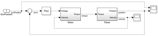
Figure 10.
The sunlight angle single-axis tracking solar system blocks on Simulink MATLAB.
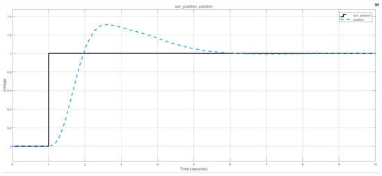
Figure 11.
Comparison between the Sun’s position and the tracker position.
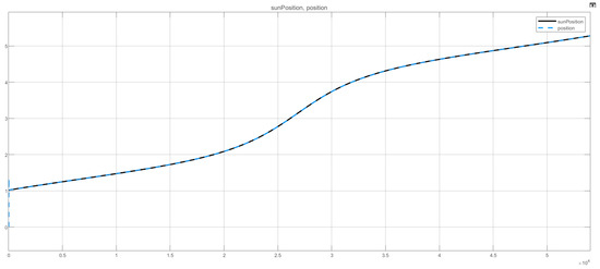
Figure 12.
The output tracking position of a single-axis tracking solar system during a day.
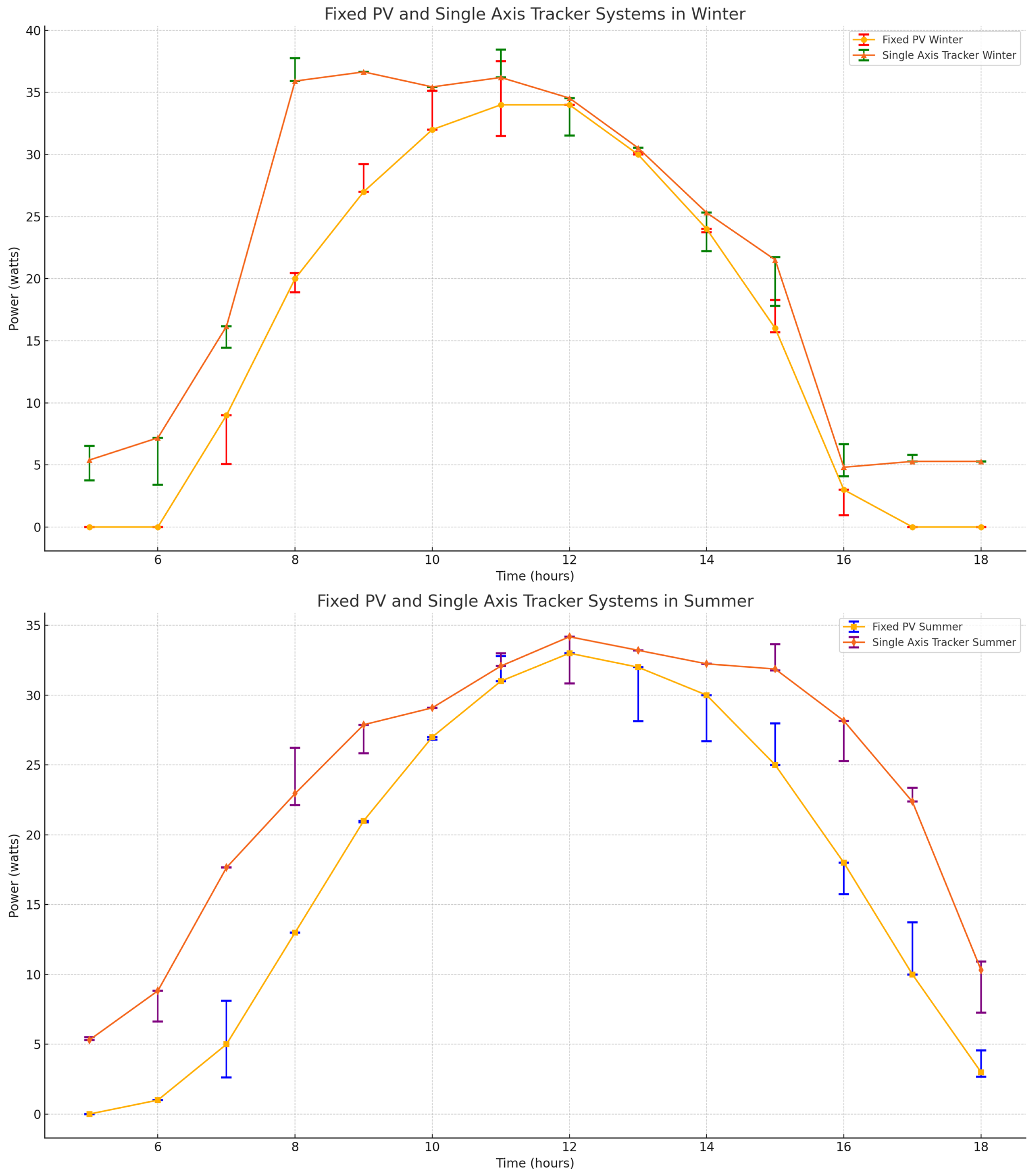
On the other hand, the proposed prototype was applied to verify the design of a single-axis sun sensor tracker. The PV system with a single-axis sun sensor tracker moves the solar panel from the east to west direction following the sunlight. Therefore, the output electric power of the solar panel is increased compared to the output electric power of a fixed-structure PV system. The comparison results of the solar panel output electric power for the proposed design and the fixed-structure system are shown in Figure 13. Several considerations concerning the experimental results are explained below:
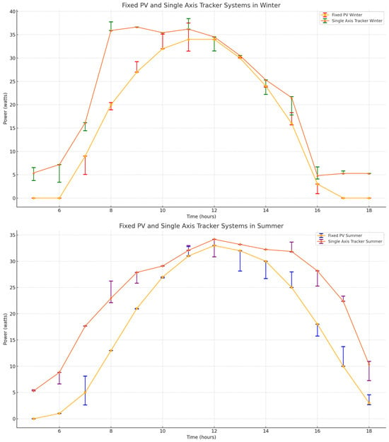
Figure 13.
The output tracking position of a single-axis tracking solar system during a day.
5.1. Fixed PV and Single-Axis Tracker Systems in Winter
The winter plot in Figure 13 shows the power output of the two systems: a fixed PV system and a single-axis tracker PV system, over a period from 5 AM to 6 PM. The y-axis represents the power output in watts, while the x-axis shows the time in hours. The power output started at 0 W at 5 AM, reached its peak of around 34 W between 11 AM and 12 PM, and then decreased back to 0 W by 6 PM. The error bars for this system represent the variability in power output based on readings taken on separate days in December, at the same time each day. These bars were relatively small in the early morning and late afternoon, indicating a lower variability in power output. The error was higher during the peak output times, particularly between 11 AM and 12 PM, showing variability due to factors like shading or weather conditions. The system performed best around noon, which aligns with the highest solar irradiance typically occurring during midday. For the PV system with a single-axis tracker, the power output also started at 5.39 W at 5 AM during a typical day of winter, reached a higher peak of around 36.65 W between 9 AM and 10 AM, and then slowly decreased to about 5.28 W by 6 PM. Similar to the fixed system, the error bars were based on experimental data from December and were larger during the peak performance hours, indicating higher variability in power output. The single-axis tracker shows a higher and more prolonged peak compared to the fixed PV system, demonstrating its effectiveness in capturing more sunlight by tracking the Sun’s movement throughout the day. The PV system with a single-axis tracker consistently outperformed the fixed PV system, providing higher power output across almost all times of the day. Both systems showed increased variability during peak hours, but the tracker system’s higher performance made it more efficient overall during winter.
5.2. Fixed PV and Single-Axis Tracker Systems in Summer
The summer plot in Figure 13 displays the power output of the same two systems, over the same time period from 5 AM to 6 PM. The y-axis represents power in watts, and the x-axis shows the time in hours. The power output for the fixed PV system started at 0 W at 5 AM, reached a peak of around 33 W between 12 PM and 1 PM, and decreased back to 3 W by 6 PM. The error bars were more significant during peak hours (12 PM to 1 PM), indicating greater variability in the power output during this period. These error bars were based on readings taken on separate days in June. The fixed PV system performed best around noon to early afternoon, reflecting the highest solar irradiance. The power output of the PV system with the single-axis tracker started at 5.3 W at 5 AM, reached a peak of around 34.18 W between 12 PM and 1 PM, and decreased to about 10.32 W by 6 PM. The error bars, derived from June data, were smaller compared to winter, suggesting more consistent performance during summer. However, there was still notable variability during peak hours. The single-axis tracker demonstrated a higher peak output and a longer duration of higher output compared to the fixed PV system, thanks to its ability to track the Sun’s movement. In summer, both systems showed improved performance compared to winter, with the single-axis tracker again outperforming the fixed PV system. The error bars suggest that the systems were more consistent in their output during summer, but the tracker system still had a slight edge in terms of stability and higher overall output.
5.3. Error Bars
The error bars in the plots represent the variability in the power output of the systems. This variability was based on experimental data collected over multiple days in the same month, at the same time each day. For the winter data, the month of December was used, while the summer data were collected in June. The error bars capture the range of power outputs observed, highlighting the impact of day-to-day variations in weather, sunlight intensity, and other environmental factors on the systems’ performances. The error bars in winter were generally larger, indicating greater variability in the power output due to more unstable weather conditions and shorter daylight hours. In contrast, the summer data show smaller error bars, reflecting more stable and consistent sunlight availability. Both in winter and summer, the single-axis tracker systems outperformed the fixed PV systems. They provided higher power output for longer periods of the day due to their ability to follow the Sun’s path. Similarly, both systems performed better in summer, reflecting the higher solar irradiance during this season. The tracker system showed less variability in summer compared to winter, indicating more stable performance in better weather conditions.
For optimal performance and efficiency, especially in areas with significant seasonal variations in solar irradiance, investing in single-axis tracker systems is recommended. They capture more sunlight and convert it into power more effectively than fixed systems. The consideration of error bars also emphasizes the importance of system stability and reliability, with tracker systems showing more consistent performance across different conditions.
The output electric power results show that the highest generated energy differences of around 52% were at the sunrise and sunset intervals, while the electric energy generated was almost the same at the noon interval. Moreover, the monthly average total generated electric power from the solar panel of the fixed-structure and proposed single-axis tracker systems obtained from the experiments is presented in Table 1. The experimental study was conducted in 2023. The size of the single-axis tracking system was 50 W. The results in Table 1 show a monthly average output of the system with and without tracking. During the winter months, the proposed design with a single-axis tracking mechanism proved to be 21% more efficient than the fixed structure, which was taken as a benchmark. However, during the summer, the experimental study data suggest that the monthly average of the single-axis tracking was 18% more efficient than that of the fixed structure. This is because of the rise in surface temperatures, which offers a negative gradient to the total generated power. However, the maximum power consumption of the DC motor for traction was 0.4 kWh, making the single-axis tacking system more efficient by an average of 15% in winters and 12% in summers.

Table 1.
Output power of benchmark system vs. the proposed single-axis solar tracking system.
A comparison of different tracking systems, i.e., the fixed-structure PV and the proposed tracking design, is shown in Table 2. Table 2 presents the comparison between the dual-axis solar tracker, which is presented in [14,18], the single-axis solar tracker explained in [11,13], the solar tracker system proposed in this paper, and a fixed-structure PV system.
Table 2.
Comparison between the proposed technique with several other techniques.
The comparison shows that the proposed technique had the lowest cost compared with the other tracking systems. Moreover, the proposed solar tracking system had higher energy harvesting compared with the fixed-structure PV system. For instance, the components of the fixed-structure solar system are a solar panel, basis structure, and inverter. The cost of a fixed-structure solar system is the lowest, as compared to the other systems, because it does not have motors and a complex structure. Also, the fixed-structure system does not require maintenance on the structure or motors, producing long-term reliability. However, the generated electrical energy is the lowest compared with the other tracking techniques because the solar panel does not follow the sunlight, with its highest generated energy being at noon when the sunlight faces the solar panel.
Conversely, the single-direction sunlight tracker system has one motor with a complex structure, and a complex tracker control system, which makes the single-axis solar tracker more costly than the fixed-structure and means it requires maintenance. However, the production of electrical energy from the single-direction tracking system is greater than from the fixed structure because the solar panel follows the sunlight in one direction. Inversely, the proposed single-direction solar tracking system has advantages over existing single-axis techniques regarding the simplicity of controlling the solar panel and the lower costs of using photodiode sun sensors. The most complex structure is used with dual-axis solar trackers. Dual-direction solar tracking systems contain two motors that increase both the cost and maintenance requirements. However, the generated electrical energy from the solar panel of the dual-direction solar tracker is the highest because the solar panel follows the sunlight in two directions.
6. Conclusions
The proposed single-axis sun sensor solar tracking system demonstrates significant advantages in terms of simplicity, cost-effectiveness, and real-time tracking capabilities. By employing four photodiode sensors to measure the angle of sunlight, the solar panel can efficiently track the Sun throughout the day, resulting in improved energy capture. The experimental results show that the proposed system generates approximately 20% more electric power compared to a fixed-structure PV system. The design balances the benefits of increased energy production with lower complexity and maintenance costs compared to dual-axis tracking systems. This makes it a practical and beneficial solution for enhancing the performance of photovoltaic systems, especially in regions with high solar irradiance like Saudi Arabia.
Funding
This work is funded by the Deputyship for Research & Innovation, Ministry of Education in Saudi Arabia through the project number IFP-IMSIU-2023073.
Data Availability Statement
Data are contained within the article.
Acknowledgments
The authors appreciate the Deanship of Scientific Research at Imam Mohammad Ibn Saud Islamic University (IMSIU) for supporting and supervising this project.
Conflicts of Interest
The authors declare no conflict of interest.
References
- Al-Othman, A.; Younes, T.; Al-Adwan, I.; Al Khawaldah, M.; Alauthman, H.; Alkhedher, M.; Ramadan, M. An experimental study on hybrid control of a solar tracking system to maximize energy harvesting in Jordan. Sol. Energy 2023, 263, 111931. [Google Scholar] [CrossRef]
- Awasthi, A.; Shukla, A.K.; SR, M.M.; Dondariya, C.; Shukla, K.; Porwal, D.; Richhariya, G. Review on sun tracking technology in solar PV system. Energy Rep. 2020, 6, 392–405. [Google Scholar] [CrossRef]
- Almasoud, A.; Gandayh, H.M. Future of solar energy in Saudi Arabia. J. King Saud Univ. Eng. Sci. 2015, 27, 153–157. [Google Scholar] [CrossRef]
- Wan, C.; Li, G.; Wang, J.; Xu, L.; Cheng, D.G.; Chen, F.; Asakura, Y.; Kang, Y.; Yamauchi, Y. Modulating electronic metal-support interactions to boost visible-light-driven hydrolysis of ammonia borane: Nickel-platinum nanoparticles supported on phosphorus-doped titania. Angew. Chem. Int. Ed. 2023, 62, e202305371. [Google Scholar] [CrossRef] [PubMed]
- Wan, C.; Li, R.; Wang, J.; Cheng, D.g.; Chen, F.; Xu, L.; Gao, M.; Kang, Y.; Eguchi, M.; Yamauchi, Y. Silica Confinement for Stable and Magnetic Co- Cu Alloy Nanoparticles in Nitrogen-Doped Carbon for Enhanced Hydrogen Evolution. Angew. Chem. 2024, 136, e202404505. [Google Scholar] [CrossRef]
- Khoshoo, B.; Madovi, O.; Aggarwal, A.; Foster, S.N. Impact of Rotor Segmentation on Electromagnetic Performance of PM Machine. In Proceedings of the 2022 International Conference on Electrical, Computer and Energy Technologies (ICECET), Prague, Czech Republic, 20–22 July 2022; pp. 1–7. [Google Scholar]
- Aggarwal, A.; Meier, M.; Strangas, E.; Agapiou, J. Analysis of Modular Stator PMSM Manufactured Using Oriented Steel. Energies 2021, 14, 6583. [Google Scholar] [CrossRef]
- Huang, S.; Aggarwal, A.; Strangas, E.G.; Li, K.; Niu, F.; Huang, X. Robust Stator Winding Fault Detection in PMSMs with Respect to Current Controller Bandwidth. IEEE Trans. Power Electron. 2021, 36, 5032–5042. [Google Scholar] [CrossRef]
- Batayneh, W.; Bataineh, A.; Soliman, I.; Hafees, S.A. Investigation of a single-axis discrete solar tracking system for reduced actuations and maximum energy collection. Autom. Constr. 2019, 98, 102–109. [Google Scholar] [CrossRef]
- Haryanti, M.; Halim, A.; Yusuf, A. Development of two axis solar tracking using five photodiodes. In Proceedings of the 2014 Electrical Power, Electronics, Communicatons, Control and Informatics Seminar (EECCIS), Malang, Indonesia, 27–28 August 2014; pp. 40–44. [Google Scholar]
- Huang, M.; Bi, Z.; Ma, J.; Zhu, X.; Zhang, J.; Man, K.L. A Novel Single-Axis Solar Tracker Based on Reinforcement Learning. In Proceedings of the 2022 International Conference on Industrial IoT, Big Data and Supply Chain (IIoTBDSC), Beijing, China, 23–25 September 2022; pp. 329–333. [Google Scholar]
- Katrandzhiev, N.T.; Karnobatev, N.N. Algorithm for single axis solar tracker. In Proceedings of the 2018 IEEE XXVII International Scientific Conference Electronics-ET, Sozopol, Bulgaria, 13–15 September 2018; pp. 1–4. [Google Scholar]
- Kabalci, E.; Calpbinici, A. Design and Implementation of Control Algorithms for Single-Axis Sun Tracking Systems. J. Power Technol. 2020, 100, 32–42. [Google Scholar]
- Suguna, R.; Priya, M.S.; Charuhasan, B.; Dhakshnamoorthy, M.; Kumar, R.S.; Prabha, K.L. Enhancement of Solar Output with Dual Axis Solar Tracker using Arduino. In Proceedings of the 2022 International Conference on Power, Energy, Control and Transmission Systems (ICPECTS), Chennai, India, 8–9 December 2022; pp. 1–5. [Google Scholar]
- Saputra, I.D.; Sajayasa, I.M.; Suryawan, I.K.; Sugirianta, I.; Purbhawa, I.M.; Putra, I.M.E. A New Approach in Controlling A Single Axis Solar Tracker Based on Photovoltaic Output. In Proceedings of the 2021 7th International Conference on Electrical, Electronics and Information Engineering (ICEEIE), Malang, Indonesia, 2 October 2021; pp. 49–53. [Google Scholar]
- Ishak, M.H.B.; Burham, N.; Masrie, M.; Janin, Z.; Sam, R. Automatic Dual-Axis Solar Tracking System for Enhancing the Performance of a Solar Photovoltaic Panel. In Proceedings of the 2023 IEEE 9th International Conference on Smart Instrumentation, Measurement and Applications (ICSIMA), Kuala Lumpur, Malaysia, 17–18 October 2023; pp. 279–283. [Google Scholar]
- Szabo, R.; Ricman, R.S. The Creation Method of a Solar Tracker Using the Zybo SoC. In Proceedings of the 2023 33rd International Conference Radioelektronika (RADIOELEKTRONIKA), Pardubice, Czech Republic, 19–20 April 2023; pp. 1–4. [Google Scholar]
- Sharma, S.; Rohilla, Y. A study-level dual-axis active solar tracker. In Proceedings of the 2021 International Conference on System, Computation, Automation and Networking (ICSCAN), Puducherry, India, 30–31 July 2021; pp. 1–6. [Google Scholar]
- Mousazadeh, H.; Keyhani, A.; Javadi, A.; Mobli, H.; Abrinia, K.; Sharifi, A. A review of principle and sun-tracking methods for maximizing solar systems output. Renew. Sustain. Energy Rev. 2009, 13, 1800–1818. [Google Scholar] [CrossRef]
- Global Solar Atlas. Available online: https://globalsolaratlas.info/map?c=11.609193,8.4375,3 (accessed on 1 January 2023).
- World Bank Group. Available online: https://www.worldbank.org/en/home (accessed on 1 January 2023).
- Nakamura, K.; Honma, K.; Ohinata, T.; Arimatsu, K.; Kojima, T.; Yamada, M.; Matsumoto, R.; Takiguchi, M.; Ichinokura, O. Development of concentric-winding type three-phase variable inductor. IEEE Trans. Magn. 2015, 51, 1–4. [Google Scholar] [CrossRef]
- Sowayan, A.S.; Tamimi, A. Comparative Prediction of Apparent Cartesian and Polar Sun Charts for Riyadh, Kingdom of Saudi Arabia. J. North Basic Appl. Sci. 2021, 6, 17. [Google Scholar]
- Time and Date. Available online: https://www.timeanddate.com/sun/saudi-arabia/riyadh (accessed on 1 January 2023).
- Chapman, S.J. Electric Machinery Fundamentals; McGraw-Hill: New York, NY, USA, 2004. [Google Scholar]


Disclaimer/Publisher’s Note: The statements, opinions and data contained in all publications are solely those of the individual author(s) and contributor(s) and not of MDPI and/or the editor(s). MDPI and/or the editor(s) disclaim responsibility for any injury to people or property resulting from any ideas, methods, instructions or products referred to in the content. |
© 2024 by the author. Licensee MDPI, Basel, Switzerland. This article is an open access article distributed under the terms and conditions of the Creative Commons Attribution (CC BY) license (https://creativecommons.org/licenses/by/4.0/).