Article

Design of Underwater Compressed Air Flexible Airbag Energy Storage Device and Experimental Study of Physical Model in Pool

1
Yantai Research Institute of Harbin Engineering University, Harbin Engineering University, Yantai 264000, China
2
College of Mechanical and Electrical Engineering, Harbin Engineering University, Harbin 150001, China
*
Author to whom correspondence should be addressed.
Energies 2024, 17(14), 3478; https://doi.org/10.3390/en17143478
Submission received: 6 May 2024 / Revised: 6 July 2024 / Accepted: 9 July 2024 / Published: 15 July 2024
(This article belongs to the Section D: Energy Storage and Application)

Abstract

:
Renewable energy is a prominent area of research within the energy sector, and the storage of renewable energy represents an efficient method for its utilization. There are various energy storage methods available, among which compressed air energy storage stands out due to its large capacity and cost-effective working medium. While land-based compressed air energy storage power stations have been constructed worldwide, their efficiency remains low. Underwater compressed air energy storage has the potential to significantly enhance efficiency, although no such device currently exists. This paper presents the design of an UWCA-FABESD utilizing five flexible air bags for underwater gas storage and discharge. Additionally, it introduces the working principle of the adiabatic underwater compressed air energy storage system and device. Furthermore, a small-scale physical model with similar functionality was designed and manufactured to simulate the charging process of the air bag in onshore charging and discharging tests as well as posture adjustment and lifting arrangement tests, along with underwater charging and discharging tests. These experiments validated the related functions of the designed underwater compressed air flexible bag energy storage device while proposing methods for its improvement. This research provides a new approach to underwater compressed air energy storage.

1. Introduction

Nowadays, the use of new sources of energy has attracted worldwide attention, and various countries and regions have conducted a lot of research in the fields of wind power generation, photovoltaic power generation, etc., but this kind of renewable energy itself has the following three problems: one is the randomness of this kind of renewable energy; Another is that such renewable energy is intermittent; The third is the low energy density of such renewable energy sources. In the use of renewable energy, there is also a mismatch between energy supply and demand in time and space [1,2]. The best way to solve these problems is to store renewable energy and transport it to where it is needed, when it is needed.
When storing renewable energy, compressed air energy storage (CAES) is a better choice. Compared with pumped energy storage, it is much less restricted by geographical location and has less damage to the ecological environment [3]. CAES is divided into land-based and underwater types, among which land-based one is a relatively mature technology. It uses existing underground caverns to convert renewable energy into internal energy of compressed air and store it in underground caverns [4,5]. The disadvantage is that underground caverns are containers with constant volume and their energy storage efficiency is relatively low [6]. The energy storage of the underwater compressed air flexible bag can solve this problem perfectly. In the process of releasing compressed air, the flexible bag will output compressed air to the turbine in the approximate isobaric process under the action of water pressure, which can ensure the stability of the air pressure. According to the literature, the output of compressed air by the isobaric process can increase the efficiency of the turbine by 10–15% [7], thus improving the efficiency of the underwater compressed air energy storage (UWCAES) system.
For land-based CAES devices, the container of compressed air is first required to have a certain structural strength and can withstand the pressure difference between the inside and outside of the container, so it is generally chosen to use a low-cost and high-strength container such as an underground cave. As the underwater compressed air flexible bag energy storage device (UWCA-FABESD) is in water, water will provide certain external pressure and reduce the internal and external pressure difference of the flexible container, so the structural strength requirement of the flexible container will be greatly reduced [8,9,10]. The deeper the water level in the location of the device, the higher the compressed air pressure in the UWCA-FABESD, and the more energy stored by the device. Offshore wind power can be developed in many coastal areas in the world, and the installation location of offshore wind power equipment has a deep enough water level, and the energy storage demand is quite large, so the UWCA-FABESD has considerable research value.
For the UWCA-FABESD, Pimm et al. first analyzed and studied the axisymmetrical tension-free film [11], and then studied the shape change of the energy bag closed at the bottom during the inflating process. Since the energy bag designed by them is composed of split parts similar to pumpkins, they also carried out axisymmetric finite element analysis of one lobe of the energy bag under different pressure differences [12,13]. Finally, they carried out tank test of the 3-m diameter energy bag at the European Energy Center in Orkney and ocean test of the 5-m diameter energy bag. In their ocean experiment, certain leakage occurred in the energy bag. However, they proved that the underwater compressed air flexible bag energy storage is feasible, and explained the subsequent improvement plan of the bag [6].
Vasel-Be-Hagh et al. [14] conducted turbulence simulation experiments on a special water-droplet-shaped flexible energy storage bag of underwater compressed air, and finally found that the average drag coefficient of the flexible bag of this shape was smaller than that of the cylindrical one and larger than that of the spherical one. Therefore, the underwater compressed air flexible energy storage bag is preferably spherical. Liu et al. [15] carried out a flume experiment and finite element simulation analysis on a spherical air bag with a diameter of 1 m, and proved that their test results in a shallow flume were in good agreement with the simulation results. Du Hongwang et al. [16] proposed a static analysis method of flexible risers connected to flexible airbags based on Cosserat theory. The model established by this method can be used to estimate the mechanical characteristics and strength of flexible risers in water, and the modeling and analysis of flexible risers can help solve the problem of the fracture of flexible risers [17].
In terms of combined underwater compressed gas flexible energy storage airbag, Vasel-Be-Hagh et al. [18,19,20] first studied the force and flow field characteristics of an independent single flexible airbag based on URAMS turbulence model and LS Dyna-SM turbulence model, and then studied the force and flow field characteristics of the combined flexible airbag in the flow field. In the simulation process, it is assumed that the shape of the flexible air bag does not change with the flow condition, which is somewhat different from the actual situation, but their research can provide valuable reference for the installation and fixing of the flexible air bag underwater.
From the above review, the energy release process of underwater compressed air flexible airbag energy storage is approximately isobaric due to the action of water pressure, which is more efficient and has greater energy storage capacity than the current land-based CAES system, and has greater development potential. Currently, research on water-based compressed air flexible airbag energy storage is usually focused on the analysis and design of the flexible airbag, with little research on the accompanying equipment and specific implementation methods. In this paper, a modular design and experimental study of a UWCA-FABESD will be conducted, combining the entire UWCAES system and its working principle. A modular device will be designed to allow five flexible airbags to store and release compressed air underwater, and a physical scale model of the device will be designed and tested in a 10-m-deep water tank to verify the feasibility of the designed device and propose improvement measures.

2. Design of Flexible Air Bag Storage Device for Underwater Compressed Gas

2.1. The Working System of Underwater Compressed Gas Flexible Air Bag Energy Storage Device

The designed UWCA-FABESD is a part of the entire adiabatic UWCAES system, and the adiabatic UWCAES system includes an offshore part and an undersea part, as shown in Figure 1. The offshore part is a set of an adiabatic air compression system and power generation system, which are generally installed on a barge or floating island. The electric energy emitted by wind turbines is converted into the internal energy of compressed air through the compressor in the adiabatic air compression air system, and the heat of the high-temperature and high-pressure compressed gas is stored. The output will be low-temperature and high-pressure compressed gas which is more suitable for storage of UWCA-FABESD. Then the low-temperature and high-pressure compressed gas is input into the UWCA-FABESD for storage. Once the stored compressed air is needed, the underwater compressed air flexible bag energy storage device will deliver the low-temperature and high-pressure compressed gas to the power generation system on the barge, and the low-temperature and high-pressure compressed air will enter the heat exchanger that stores heat. The heat exchanger then heats the compressed air, and finally the high-temperature and high-pressure compressed air enters the turbine, making the turbine rotate at a high speed, and the turbine is connected to the generator to generate electricity, which is the working process of the whole adiabatic compressed air energy storage system. The designed UWCA-FABESD works in the adiabatic system, which will make the whole system more efficient [21,22,23].
Figure 1 shows the layout of an UWCA-FABESD, which can store a large amount of energy when multiple designed devices are arranged in an array on the seabed. The design concept of this device is different from other UWCA-FABESD in the past. Other designs basically do not consider the design of the related supporting devices of the energy storage air bag, or mention that it is placed on the water surface. The device designs five airbags and their supporting devices into one module, which can better standardize the design standards and parameters and simplify the installation process of the energy storage device.
The device is installed by first using a crane to lift the device and the fixed anchor connected to it via an underwater fixed cable to the water, then adjusting the variable ballast tanks to regulate the buoyancy and posture of the device, allowing it to descend steadily to the desired depth. The fixed anchor is then embedded in the seabed to secure the device, and the lifting cable can be released using an ROV. Figure 2 shows the installation process. Installing the device using an underwater fixed cable can reduce the requirements for the installation environment and enhance its environmental adaptability. Adjusting the length of the fixed cable can ensure that each underwater compressed gas flexible airbag energy storage device is located on the same plane, ensuring the stability of the output pressure. Additionally, when a large number of devices are deployed on the seabed, position identification balls are set to remind surface vessels, preventing accidents from occurring.
Before the design of the part below the sea surface, some system parameters should be determined first. Table 1 shows the designed parameters of working system. The designed working depth of the UWCA-FABESD is 700 m, and the pressure of the gas storage is 7 MPa. Because the pressure increases about 0.1 MPa for every 10 m drop in the depth of water, when the storage pressure is 7 MPa, the internal and external pressure of the flexible air bag is basically equal, and the flexible air bag is basically not subject to external force, and the self-strength requirement of the flexible air bag is not too high, which can reduce the manufacturing cost and increase its service life. When the air bag is in water, there is a water pressure difference ΔP between the top and the bottom, and the diameter of the air bag is designed to be 3 m, which can make the ΔP less than 0.5 atmospheric pressure, improve the service life, and can be tested indoors. In the level 3 sea state, the wave height is 0.5 to 1.25 m, and the white spray begins to form [24], which causes a large displacement impact on the floating objects at sea. In order to ensure the safety of installation and the accuracy of installation site, the installation sea state of the whole system is set at or below the level 3 sea state.

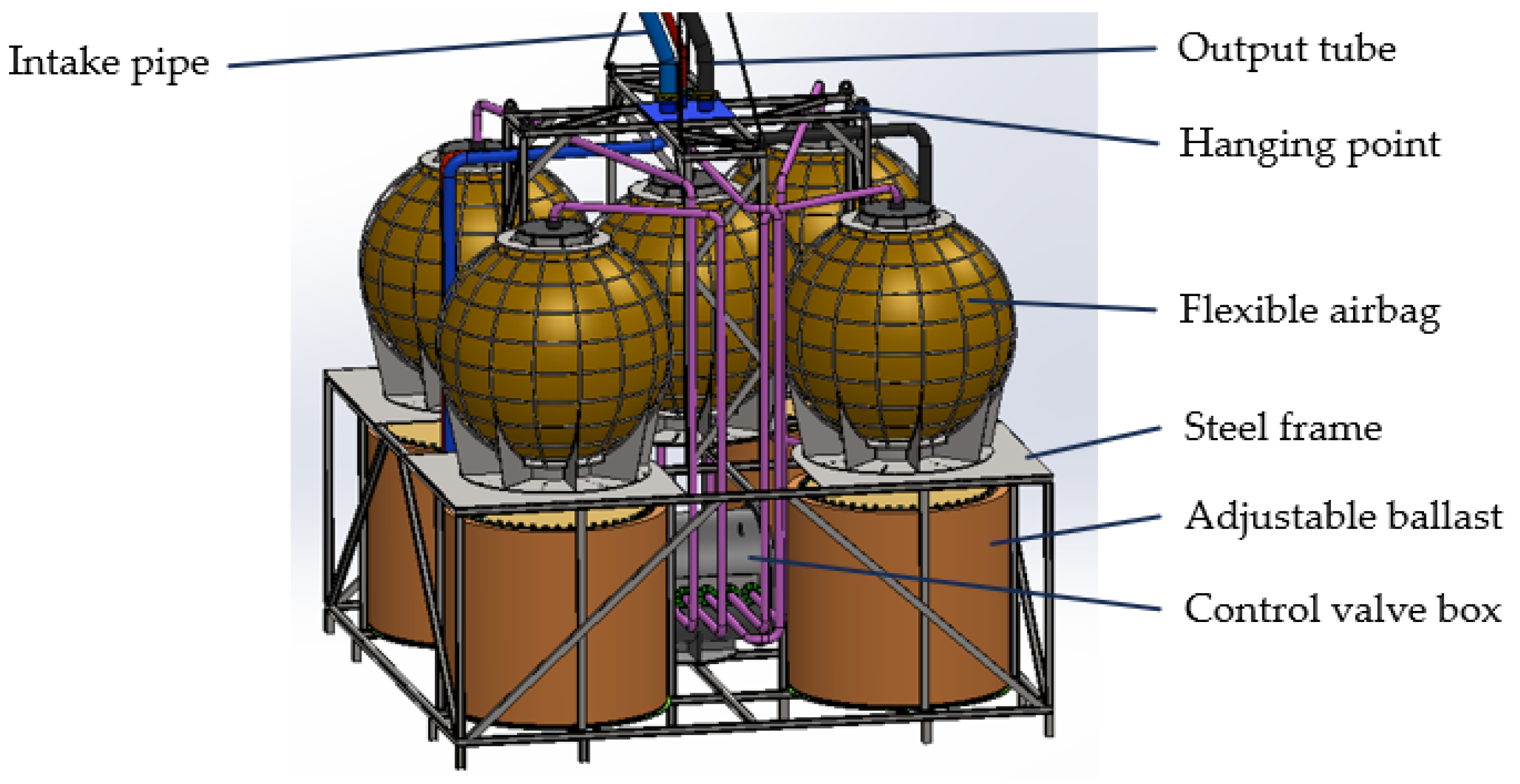
2.2. Design and Calculation of Flexible Air Bag Storage Device for Underwater Compressed Air

The designed UWCA-FABESD is composed of five flexible gas storage bags, four adjustable ballasts, a control valve box, the overall supporting steel frame, and pipelines. The structure is shown in Figure 3, and its structural parameters are shown in Table 2. The five flexible airbags are independent from each other, and they are distributed at the four corners and center of the device for storing the input low-temperature and high-pressure gas. There is an adjustable ballast at the bottom of each air bag at the four corners, and a pneumatic ball valve at the bottom of each adjustable ballast, which can control whether the internal of the adjustable ballast is connected with the sea. At the top, there is an air inlet for injecting high-pressure gas into the internal of the adjustable ballast, discharging the internal water of the adjustable ballast, and changing the quality of the overall device and change the buoyancy of the device in the sea. Below the middle airbag is the control valve box used to distribute low-temperature and high-pressure gas to each flexible airbag and adjustable ballast of the device. These devices are mounted on welded steel frames, and the whole device is connected with a flexible tube to input high-pressure gas to the device, a flexible tube to output high-pressure gas to the turbine, and a flexible tube to protect the cable. These three flexible tubes are connected to the device from the sea surface, and the flexible tube is installed with a counterweight to balance the buoyance of the flexible tube. And the counterweight can adjust the shape of the flexible pipe in water into the gentle slope type that is most conducive to gas transportation [25,26].
The steel frame connecting all parts of the device is made of 100 × 100 × 6 × 8 H-shaped steel, the material of which is Q235. H-shaped steel has strong bending resistance in all directions [27], which is suitable for being the main stressed structural parts in complex Marine environments. There is a solenoid ball valve in the control valve box to control whether the airbag air path and the adjustable ballast air path are connected. When the device starts to vent, the airbag will become smaller and the buoyancy force of the device will be reduced. At this time, high-pressure gas will be injected into the adjustable ballast and seawater will be discharged, so that the gravity and buoyancy of the device will be balanced, so that the position of the device will not move very much during the process of venting. At the beginning of the gas storage, the air bag and the adjustable ballast gas path are connected first, and then the channel between the adjustable ballast and seawater is opened. The high-pressure gas inside the adjustable ballast will enter the air bag under the pressure of seawater. After the gas in the adjustable ballast is completely transferred to the air bag, if the gas volume in the air bag is not up to standard, the compressed air will be injected into the air bag separately. During this process, the total volume of the device remains constant, thereby ensuring that the resultant force acting on the device in the sea remains unchanged throughout both gas storage and discharge processes. This effectively reduces fatigue loss in the fixed cable.
The ratio of buoyancy and gravity of the designed device i B / G is calculated as follows:
i B / G = ρ s V i m a
In the formula, ρ s is the density of seawater, which is 1.07 g / cm 3 ; V i is the flexible air bag after inflation of the device, which can adjust the volume of the ballast and control valve box; the density of the steel frame used is much higher than the density of seawater; in order to simplify the calculation, the volume calculation is not included; m a is the total mass of the device, which can be seen from Table 1 and is 94.2 t; V i is calculated and included in Table 3.
By bringing the volumes of the first three items in Table 3 into Equation (1), the ratio of buoyancy and gravity of the device on the sea surface can be obtained as
i B / G 1 = ρ s V i m a = 1.65 > 1
It can be found that i B / G 1 is greater than 1, so the device can float on the surface of the water when there is no water inside the adjustable ballast, which is convenient for operators to carry out some surface tests and inspections before diving.
When all seawater is injected into the adjustable ballast, the volume of the whole device is subtracted from the volume of the adjustable ballast cavity, and the buoyancy gravity ratio of the device is
i B / G 2 = ρ s V i m a = 1.02
It can be found that the buoyancy gravity ratio of the device at this time is slightly greater than 1, so when the device is fixed at the bottom of the water, even if the air bag is filled with gas, under the action of adjustable ballast, the device can maintain a vertical posture under the action of buoyancy, and will not exert a large pull on the cable of the fixed device. When the flexible air bag of the device releases gas, under the action of adjustable ballast, the device can be sunk into the water to meet the installation requirements.
When the device is recovered or submerged in water, the volume of the air bag is controlled at an unfilled value. At this time, in the process of adjusting the adjustable ballast, the i B / G of the device will be 1 at some point. After passing this moment, the acceleration a 0 of the device is only related to the change of water level Δ h in the adjustable ballast, which can be expressed as
a 0 = 4 π ρ s 1.3 2 Δ h m a = 6.76 π ρ s Δ h m a
The velocity of the device is
v = 0 t a 0 t = 6.76 π ρ s m a 0 t Δ h t
Therefore, when the speed of the device needs to be controlled with the crane, only the water level inside the adjustable ballast needs to be controlled.

3. Airbag Inflation Simulation Test and Physical Model Test

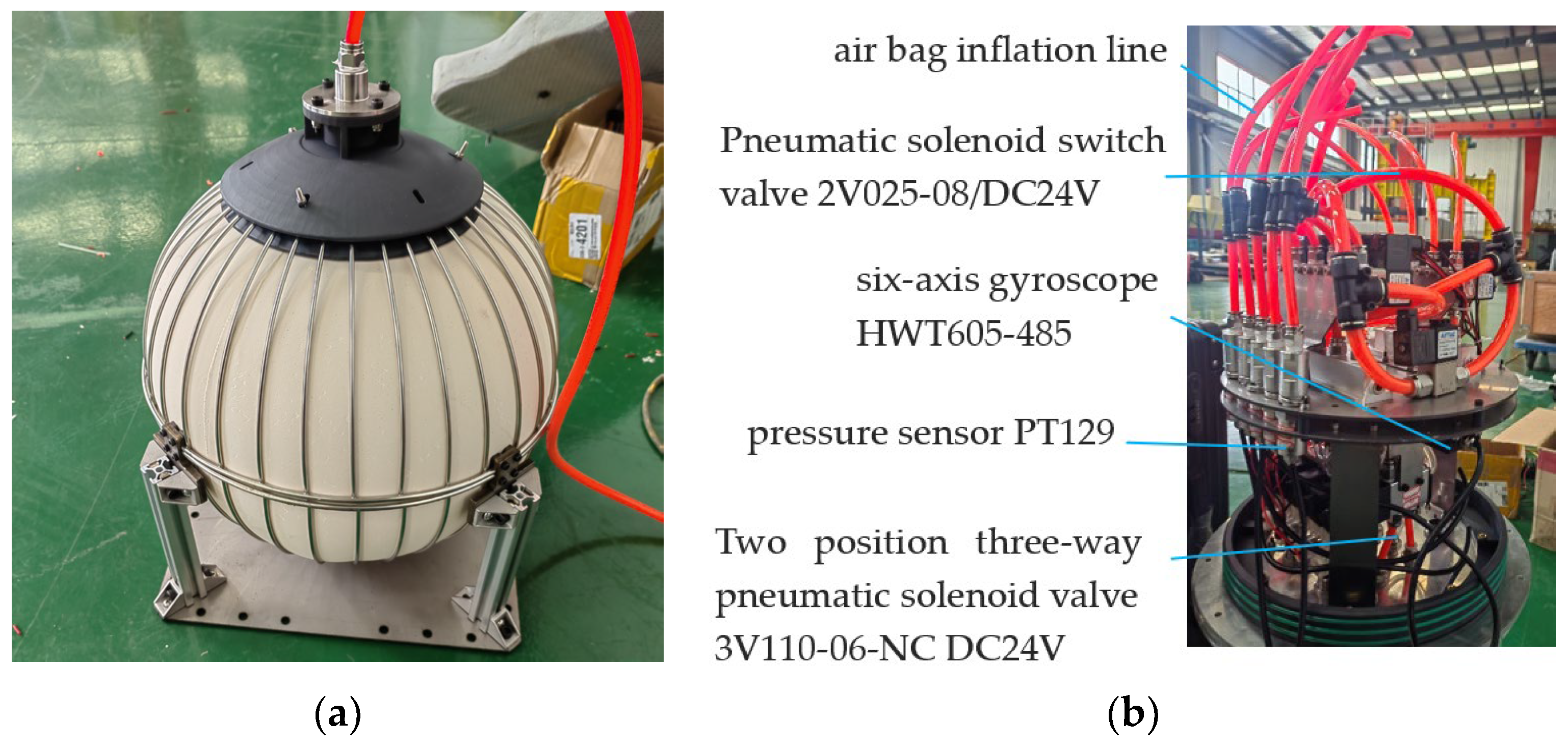
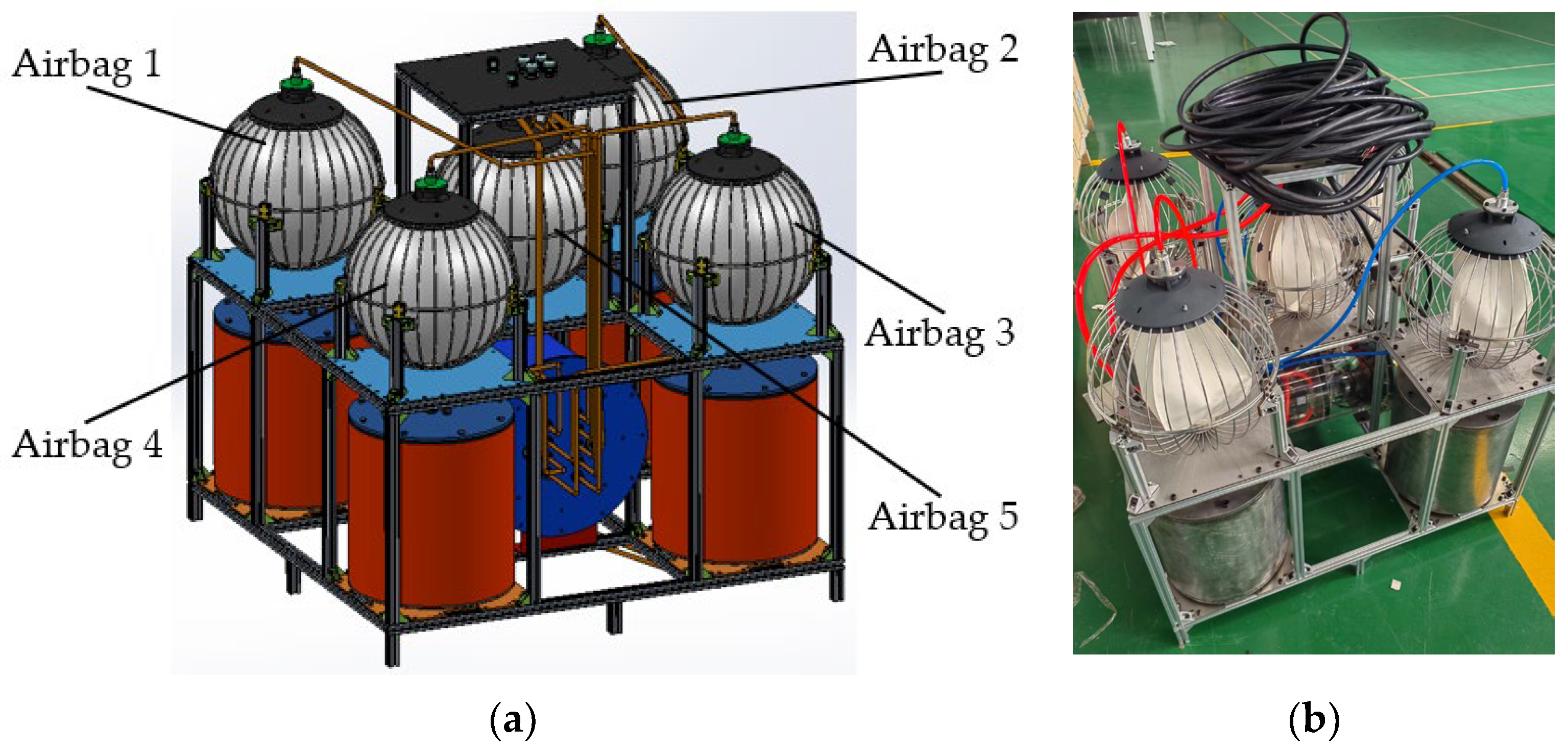
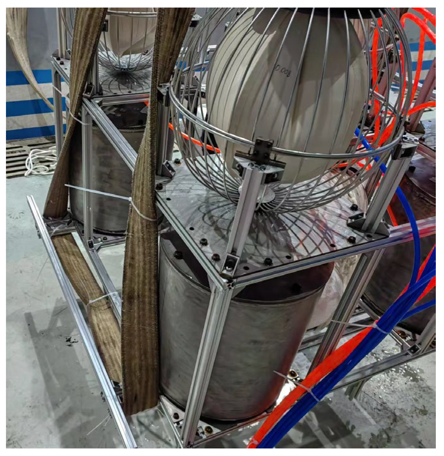
3.1. Test Models and Objects

Since the designed model is for real engineering use, the size is too large and the manufacturing cost is too high, so it is decided to use an equal ratio model in the test. The two models are geometrically superior to each other. The inner diameter of flexible airbag of the designed engineering model is 3 m, the rated inner diameter of flexible airbag of the designed test model is 30 cm, the diameter ratio is 10:1, and the volume ratio is 1000:1. The designed test model is similar to the design engineering model in structure, with a total of five air bags, four adjustable ballasts, and one control valve box. The whole is built with the model 2020L European standard aluminum, and the other plates are made of 304 stainless steel. The two models are functionally identical, the air path is the same, and the adjustable ballast of the test model can also adjust the buoyancy and posture. The size parameters of the test model are shown in Table 4, and the model diagram and the physical diagram are shown in Figure 4.
Before the test, a single airbag was inflated first to measure the internal air pressure value when the airbag was fully expanded. Figure 5 shows the state of a single airbag when it was fully expanded and the position of the air pressure sensor PT129 in the control valve box. The pressure sensor connected in parallel with the airbag measures the increased pressure inside the airbag when it is fully inflated on shore, which is 0.075 MPa. The pressure measured by the pressure sensor is the increased pressure after eliminating atmospheric pressure. At this time, the pressure is the pressure Pp that holds the airbag to a predetermined volume. Therefore, after inflating underwater, the pressure Pf when the airbag reaches full expansion should be:
P f = P p + P w
In the formula, Pw is the static water pressure, so it is only necessary to know the water depth at which the device is located to predict the internal air pressure that the sensor can measure when the airbag fully expands during underwater inflation.
Figure 5. Parts of the structure of the experimental model of UWCA-FABESD: (a) The inflated airbags; (b) The interior of the control valve box in the physical model.
Energies 17 03478 g005

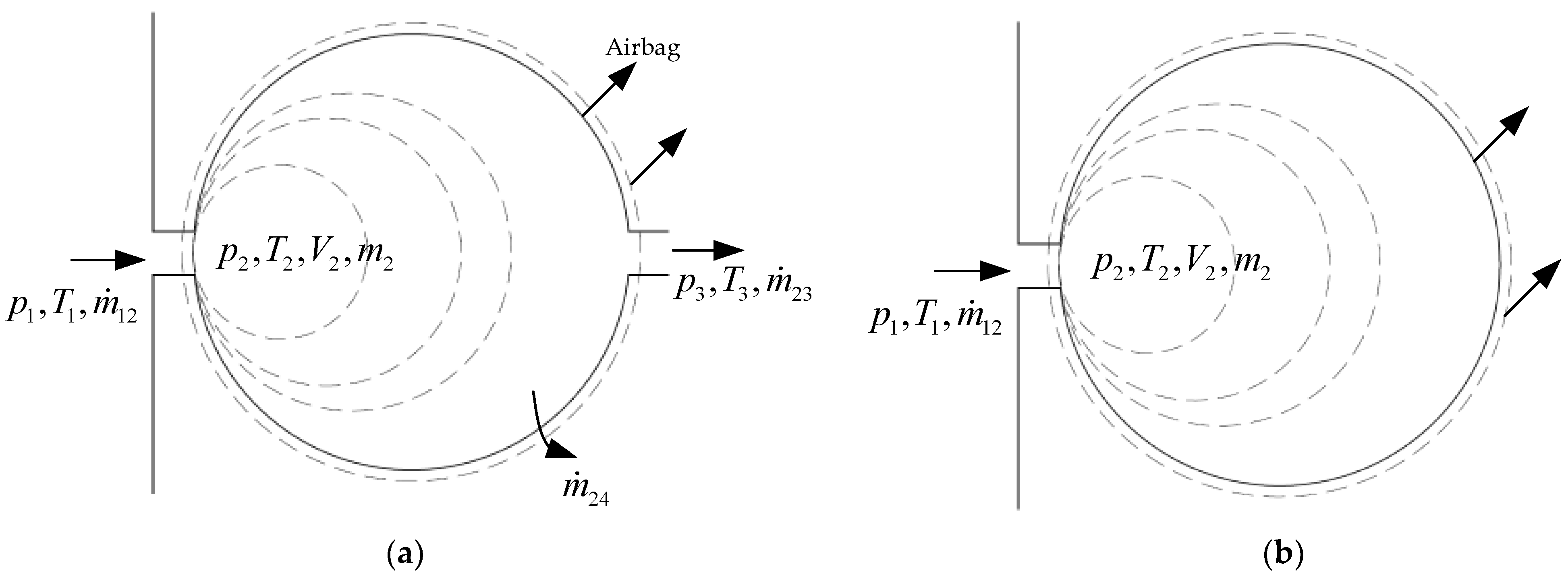
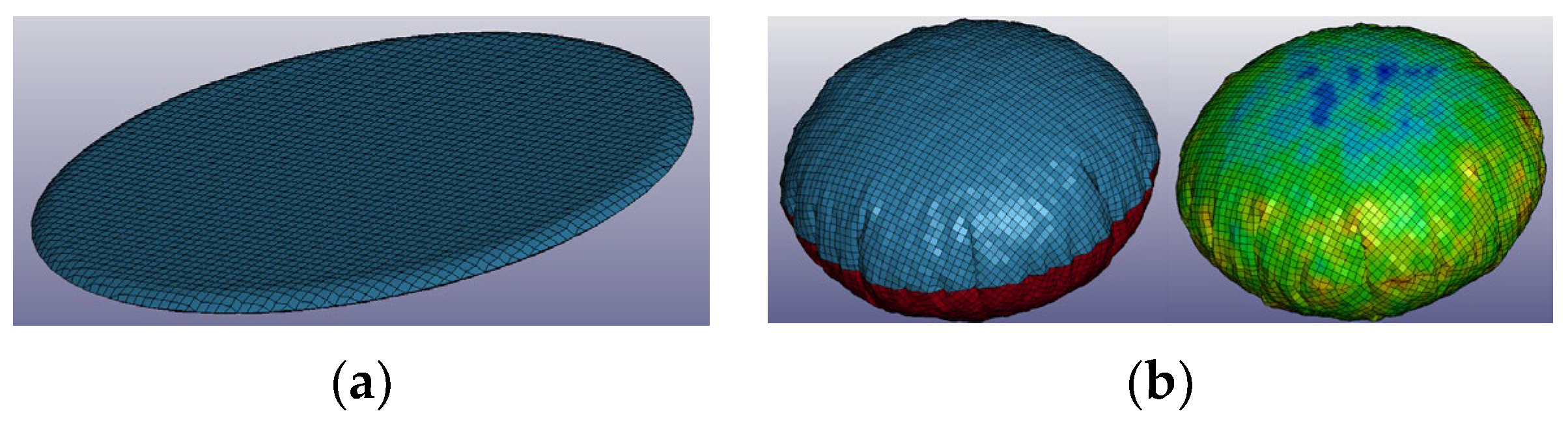
3.2. Airbag Inflation Simulation Test

The physical model test mainly tests the pressure curve of the inflation and deflation process of the flexible airbag, while the simulation test mainly simulates the underwater inflation of the airbag, observing the degree of conformity between the pressure curve inside the airbag during the underwater inflation process and the actual pressure curve obtained from the test. In the process of airbag inflation, the airbag is regarded as a continuously expanding control volume, which is composed of small shell units as the control surface. Using the CV expansion method [28,29], it is believed that the interior of the airbag is under constant pressure, the inflation process is quasi-static, and the inflation process is adiabatic. The gas pressure inside the airbag is calculated through the gas state equation:
p = ( γ 1 ) ρ e
γ = c p c v
In the formula, p is the pressure inside the airbag, γ is the specific heat ratio of the gas, ρ is the density of the gas, e is the specific internal energy of the gas, c p is the specific heat of the gas at constant pressure, and c v is the specific heat of the gas at constant volume. In a certain state, the gas volume inside the airbag is V , the mass is M , and the internal energy of the gas inside the airbag is E . Based on the definitions of gas density and specific internal energy, it can be concluded that:
ρ = M V e = E M
By substituting Equation (9) into Equation (7), it can be concluded that
p = ( γ 1 ) E V
In the numerical simulation process, the control volume can be obtained by integrating the unit area of the airbag surface
V = d x d y d z = x n x d Γ
x n x d Γ i = 1 N x i ¯ n i x A i
In the formula, N is the total number of shell elements, i is the number of shell elements, x ¯ i is the average coordinate value of the i-th element, n i x is the cosine value of the angle between the surface normal vector of the i-th shell element and the x-axis, and A i is the surface area of the i-th shell element. From Equations (11) and (12), the control volume of the airbag can be obtained as
V i = 1 N x i ¯ n i x A i
Figure 6a shows a general model for solving the airbag inflation process using the control volume method. For the airbag in this model, there is only one air inlet and no air outlet during inflation. The material used is dense latex, and it is considered that there is no surface leakage, as shown in Figure 6b.
In Figure 6, m is the mass flow rate of the gas. For Figure 6a, the mass increment of the gas inside the airbag is:
m ˙ i n = m ˙ 12 ( m ˙ 23 + m ˙ 24 )
For the model in Figure 6b, due to the absence of gas discharge and gas leakage from the airbag surface, the mass increment inside the airbag is:
m ˙ i n = m ˙ 12
During the simulation process, the mass flow rate and temperature of the gas generated by the air pump are set. According to the formula for calculating the internal energy of the gas, the internal energy increment of the gas inside the airbag is
E ˙ i n = c p m ˙ i n T i n
So, during simulation, after setting the time step Δ t , the energy of the gas inside the airbag at time n + 1 is
E n + 1 = E n + E ˙ i n Δ t ( P n + 1 P n ) ( V n + 1 V n )
In Equation (17), ( P n + 1 P n ) ( V n + 1 V n ) represents the internal energy consumed during airbag expansion. Therefore, according to Equations (17), (13) and (10), the pressure inside the airbag at time n + 1 can be obtained as
P n + 1 = ( γ 1 ) E n + 1 V n + 1
The simulation software L S D Y N A is used to model an airbag with a diameter of 300 mm. To reduce the calculation volume, the uniform pressure method is adopted, so the keyword *AIRBAG_WANG_NEFSKE is selected, and the mesh size is set to 10 mm, which can improve the efficiency of the calculation and have good accuracy. The ambient pressure is set to 0.09 MPa, because when the actual physical model starts inflating, the inside of the airbag is connected to the atmosphere, and the actual external pressure is hydrostatic pressure. The sensor measures the pressure after eliminating atmospheric pressure. According to the actual airbag material used, the simulation material is selected as *SIMPLIFIED_RUBBER. According to the used compressor displacement of 390 L/min, when simulating, one airbag is inflated. In the actual inflation process, it is believed that five airbags are equally distributed by the compressor output compressed gas, and the air density ρ A is 1.29 kg / m 3 . Based on this, the gas mass flow rate during inflation can be calculated as follows.
d m d t = ρ A 390 5 × 60 × 10 3 = 0.001677   kg / s
Based on the above key data, a model of the airbag was established as shown in Figure 7a. The simulated airbag is shown in Figure 7b, and Figure 8 shows the pressure curve during the inflation process of the simulated airbag. Due to the external pressure set at 0.09 MPa, the final pressure of the simulated airbag should be 0.165 MPa, as shown in Equation (6). The curve shown in Figure 8 was obtained through simulation with the airbag pressure reaching 0.165 MPa as the termination condition.

3.3. Experimental Scheme

Figure 9 shows the overall program flow of the experiment. An air compressor with a displacement of 390 L/min is utilized to provide gas supply to UWCA-FABESD throughout the experimental procedure. During the underwater experiment, an underwater camera is employed for observing the subaquatic state of the experimental device, including the inflation and expansion process of its air bag as well as gas contraction processes, descending process, ascending process, etc.
The experiment utilizes the STM32F03ZET6 microcontroller to receive the operation instructions from the upper computer VOFA+ and then converts the operation instructions into the switching sequence of the solenoid valve. The pressure sensor PT129 is used to collect the pressure data of the flexible airbag in the experimental device and send it to the MCU. The MCU processes the data and sends it to the upper computer for display and storage. Meanwhile, the six-axis gyroscope HWT605-485 (Purchased from Wit-motion Company in Shenzhen, China) can collect the posture data of the experimental device and send it to the MCU. The MCU uses its internal control algorithm to process the data and outputs the switching sequence instructions of the pneumatic solenoid valve that can adjust the positioning of the entire experimental device. This process is actually a fuzzy PID algorithm process; especially when the experimental device is sinking, it needs to continuously adjust its posture to keep the experimental device vertically descending.
The experimental device needs to be lowered into the water using a crane with a load capacity of 25 tons, which should be slowly lowered into the water. During the descent of the device, the crane should accompany the device in descending, and the lifting rope must remain loose to ensure that the crane does not interfere with the descent or ascent process. Figure 10 shows the structure and lifting plan for one side of the experimental device used for lifting.

3.4. Ashore Charging and Deflating Test

The experiment was first carried out on land to check whether there was any gas leakage, and the result was that after waiting for 10 min, the sound of gas leakage was not heard during the waiting process, the airbag did not become smaller, and the value of the pressure sensor PT129 has also remained unchanged, so the designed structure had no problem with airtightness on land. Figure 11 shows the test setup after inflation on shore.
After the device was flushed on shore, the deflation test was carried out. Figure 12 shows the measured pressure curves inside the five airbags during the shore deflation process, the black PT1 curve corresponds to the pressure change inside the No. 1 airbag, the green PT2 curve corresponds to the pressure change inside the No. 2 airbag, the blue PT2 curve corresponds to the pressure change inside the No. 3 airbag, the orange PT4 curve corresponds to the pressure change inside the No. 4 airbag, and the red PT5 curve corresponds to the pressure change inside the No. 5 airbag.
As can be seen in Figure 12, all five curves drop rapidly first, then release gas smoothly, and when the gas is about to be consumed, all five curves drop rapidly again, and eventually the air pressure all drops to 0. Therefore, when the airbag is really carrying out its work, the whole compressed air energy storage system should be able to supply power to the outside smoothly in the smooth deflating phase. Additionally, the fact that the five airbags have manufacturing errors leads to different elastic coefficients, which causes the airbags to contract at different speeds. The fact that the lengths of the tubes connected to each airbag, the length of the bends, and the degree of curvature are different leads to different gas release rates in the airways. These two factors ultimately result in low convergence of the five curves. When multiple airbags are deflated simultaneously on land, some airbags may have fully released their gas, while others may still have gas remaining, which will reduce the efficiency of doing work outside. It can be seen from the figure that airbag 4 contracts the fastest, airbag 3 contracts the slowest, airbag 1 and airbag 2 have parameters that are basically the same, and airbag 5 contracts the second fastest.

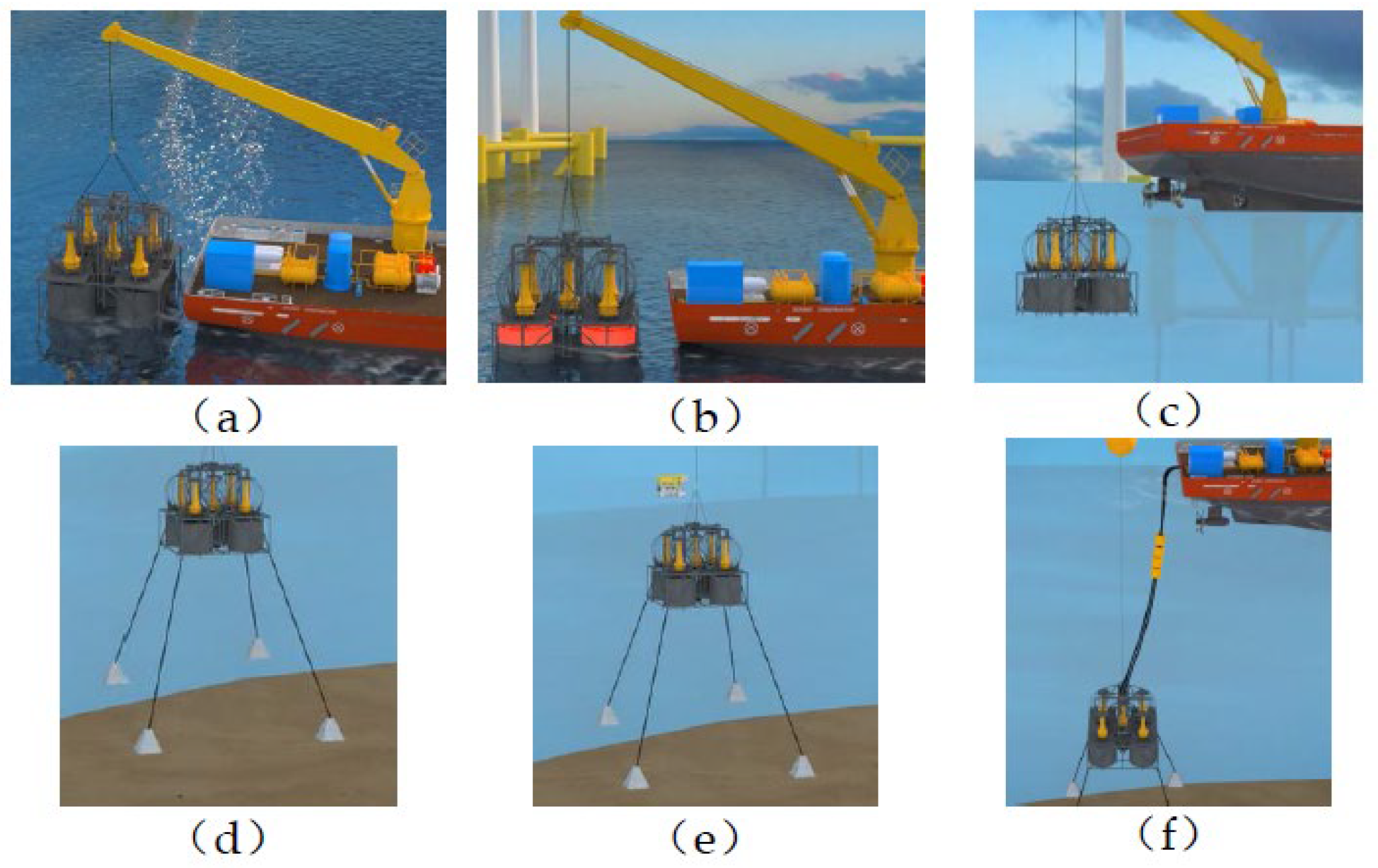
3.5. Device Posture Adjustment and Layout Test

After completing the onshore inflation and deflation test of the airbag, the lifting and layout test of the UWCA-FABESD began. The entire experiment was conducted in a 10-m-deep pool, with a maximum load of 25 tons of aerial crane assisting. Figure 11 shows the experimental process. Place the device into the water tank. As the ratio of buoyancy to gravity is less than 1, the device will float on the water surface. Then, open the pneumatic butterfly valve at the bottom, and the water will enter the adjustable ballast. Bubbles will emerge from the bottom of the device and it will start to sink, as shown in Figure 13a. The device continued to sink until it was completely submerged in the water, as shown in Figure 13b. At this point, it was found that the device tilted to the bottom right corner, and the device began to adjust through the control algorithm and continued to sink. In Figure 13c, it can be seen that the device has been leveled, but the bottom right corner is not tilting. Wait for the device to continue sinking and touch the bottom. Through the underwater camera installed on the device, it can be seen that the device has reached the bottom of the pool, as shown in Figure 13d. From the moment the device touched the water surface to the point where it reached the bottom of the pool, the smoothest descent took 4 min and 49 s. Through this test, it can be seen that the adjustable ballast of the device can play a role in adjusting the posture of the device during the sinking process, so that the device can reach the predetermined position smoothly.

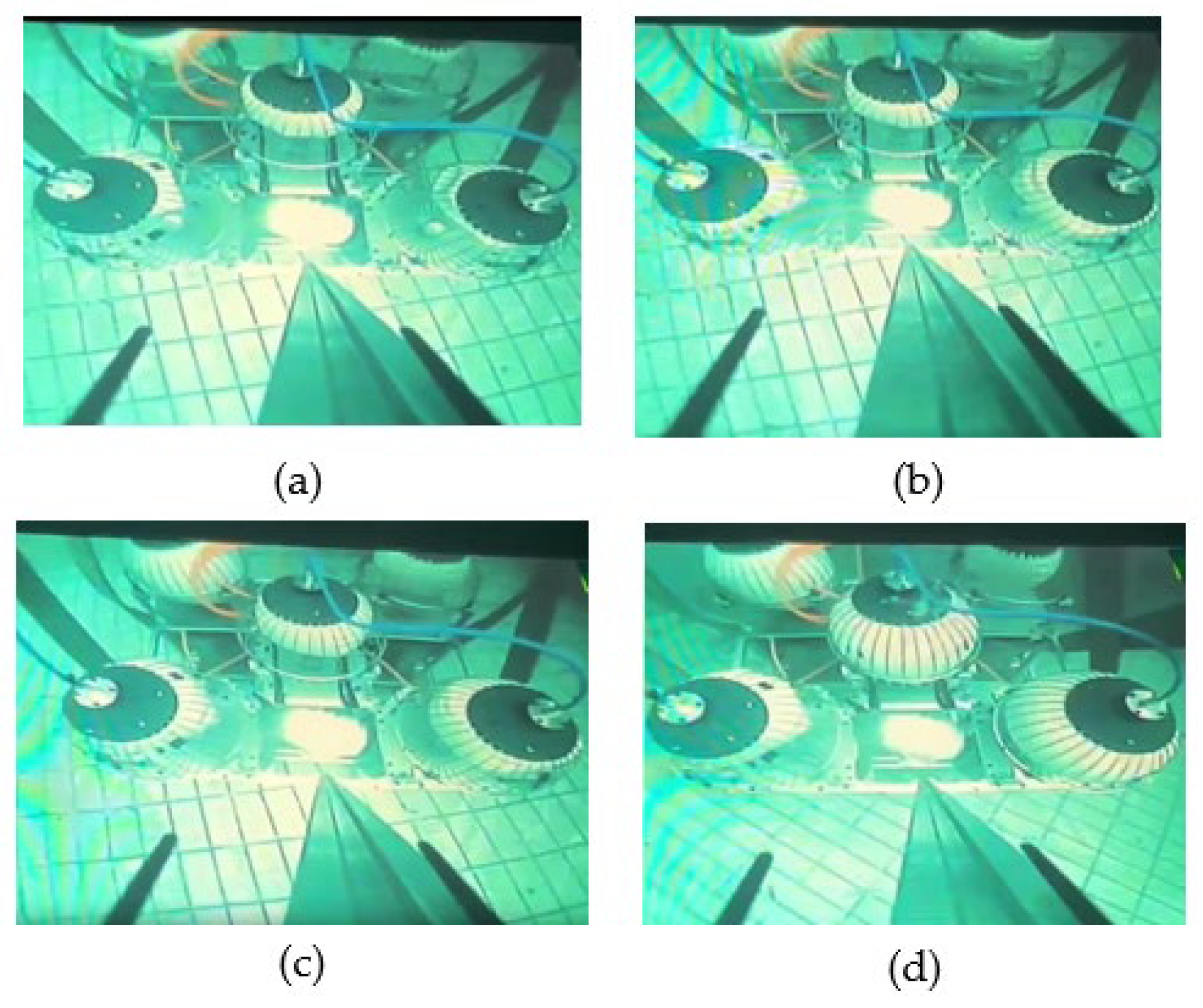
3.6. Underwater Inflation and Deflation Test

After the device reached the predetermined position, underwater inflation and deflation tests were conducted. Figure 14 shows the underwater inflation process, where all airbags are initially in a gas-free state. At this point, it is found that under the buoyancy effect, the gas-free airbags float upwards and are all attached above the protective steel mesh. Therefore, it can be verified that the steel mesh plays a role in protecting the airbags and limiting the position of the airbags, as shown in Figure 14a.
After the air pump began to inflate, the airbag began to expand, as shown in Figure 14b. The expansion process is shown in Figure 14c. When some of the airbags have been fully inflated, there were still some airbags that had not fully inflated, as shown in Figure 14d. After standing in water for 10 min, it was found that the air pressure did not decrease and the airbag did not change, so there was no leakage problem. After analysis, it was believed that the main reason was the problem of airflow. The air inlets of the five airbags all came from a single air tube. Firstly, there was an uneven distribution problem. In addition, due to the connection of the air circuit inside the valve box through the air tube, the length was different and some were bent, which affected the consistency of the air circuit, resulting in relatively large resistance in some air circuits. During the inflation experiment on shore, the external pressure of the airbag was very low, and the obstruction phenomenon of the air circuit during inflation was not obvious. When underwater at a depth of 10 m, the external pressure of the airbag increased by about double, and the larger external pressure magnified the obstruction phenomenon of the air circuit. It was originally difficult for gas to enter the airbag, so it would prefer to enter the airbag with less resistance along the way, similar to the effect of resistance in an electrical circuit. Therefore, to change this phenomenon, it is necessary to optimize the air circuit of the device to ensure that each air circuit can be distributed with equal flow of gas, and minimize the bending part of each air circuit to ensure that each air circuit has consistent length.
Figure 15 shows the pressure curve in the air bag when measured during underwater inflation. Since the external base pressure is 0.9 MPa, the pressure rises quite quickly, and after the pressure rises to the maximum, it begins to stabilize for a period of time, and then drops to a stable value. Compared with the onshore inflation test, due to the existence of basic air pressure and water pressure, the air pressure in the pipeline rises faster, and after reaching the peak, the speed of falling to the stable maximum is also much faster, which is one of the advantages of the underwater environment to the compressed gas energy storage device, making the air pressure convergence faster.
Compared with the simulated curve in Figure 8, the pressure increase process is faster and smoother than that of the simulated curve, but the air pressure starts to increase from 0, because the actual pressure needs to rise gradually, and the pipeline where the pressure sensor is located is connected with the external atmosphere, so it begins to detect the external pressure, and its own algorithm results in a detection value of 0. It is not the water pressure at the location. In addition, in the process of balloon expansion, the nearby water will have a complex flow. Under the action of water flow, there is also a small range of shocks near the final value of air pressure in the balloon at the beginning, but it stabilized after 1.8 s.
Figure 16 shows the pressure curves inside the five airbags during underwater deflation. Compared with the onshore gas release process, the consistency of the five curves during underwater gas release is much better than that of onshore gas release. This is because under the action of water pressure, the airbag can be quickly compressed, allowing the gas to be quickly and consistently discharged. This is another benefit that the underwater environment brings to compressed gas energy storage devices, which is to increase the stable and rapid discharge of gas, reducing the inconsistency of gas transmission caused by the inconsistency of the airbag.
In the pressure curve of the airbag for underwater deflation, the pressure was basically stable at 0.8 MPa and outputted outward. After analysis, it was believed that the output pressure was smaller than the actual output pressure. The pressure of 0.8 MPa is not the actual output pressure, and the actual output pressure should be closer to the pressure at the beginning of deflation. The main reason for this situation is that the connection between the pressure sensor and the airbag is similar to a Venturi tube [30,31], as shown in Figure 17. When the gas starts to accelerate outward and output, the gas flow rate in the main gas path is greater than that in the sensor gas path. The gas in the sensor air circuit is sucked out, causing a decrease in the pressure detected by the sensor. After the flow rate of the main air circuit stabilizes, the detected pressure stabilizes at a small value. After the gas in the airbag is consumed, the pressure quickly drops to 0. Through this experiment, it can also be found that the working pressure of the UWCA-FABESD should also be the stable outward output gas pressure of the airbag, not equal to the air pressure inside the airbag.
The pressure curves in Figure 12 and Figure 16 both reflect that during venting, the pressure inside the pipeline first rapidly decreases and then stabilizes at a certain pressure value. During the pressure drop stage of the initial deflation, the entire underwater compressed air energy storage system should not generate electricity externally. The underwater compressed air flexible airbag energy storage system should work at a stable pressure value during the deflation stage to ensure the safety of the power transmission and consumption network. In the final stage of deflation, almost all the gas inside the airbag is released, and the pressure in the gas path rapidly decreases again, which will also have an impact on power generation. Therefore, in the actual use of underwater compressed air energy storage systems, the compressed gas inside the airbag should not be completely consumed.

4. Conclusions

The article first introduces the insulation system of the UWCA-FABESD, and then designs an UWCA-FABESD. The device integrates five flexible airbags into a gas storage module, which can convert renewable energy such as offshore wind power into low-temperature high-pressure compressed gas for storage. When needed, it can output compressed gas for power generation, and can adjust its buoyancy and gravity ratio, control its posture, and control the magnitude of the resultant force on the device during installation and recovery processes. The designed device provides a new approach and design for underwater compressed air energy storage, adding research on multi airbag combination energy storage.
In order to verify whether the designed device can work properly, the inflation process of the airbag in the small physical model was first simulated, and the simulated pressure curve of the inflation process was obtained. Then, a small physical model with the same function was designed and manufactured for testing. The onshore inflation and deflation tests, posture adjustment and layout tests, as well as the underwater inflation and deflation tests of the small physical model were carried out, and the following conclusions were obtained:
  • A physical model designed with the same functionality as the engineering model can function properly. Adjustable ballast can adjust the posture of the UWCA-FABESD and its buoyancy and gravity ratio. The designed steel mesh cover of the airbag can protect the airbag while limiting its displacement and expanded shape. The device can store compressed air and release compressed air normally;
  • The static pressure of water can increase the pressure of gas storage, improve the efficiency of UWCAES systems, assist airbag contraction, improve the consistency of external deflation of the five airbags, and reduce the manufacturing requirements of airbags, and lower costs;
  • The designed UWCA-FABESD should output to the outside during the stable deflation stage of the airbag. It is not recommended to generate electricity at the beginning of deflation. When truly deflating to the outside, the gas in the airbag should not be completely discharged, and a portion of the gas should be retained inside the airbag to ensure that the gas flow rate and pressure in the tube remain unchanged when deflation is about to end;
  • When inflating the device, in order to ensure that the airbags are fully charged at the same time, it is necessary to ensure that the length of the intake pipeline of each airbag is consistent, minimize the bending part of the gas pipeline, and allow each airbag to be inflated separately. When some airbags are not fully charged, they should be inflated separately to improve the utilization rate of the airbags.

Author Contributions

Conceptualization, writing—original draft preparation, X.R., W.P. and Z.W.; Supervision, X.R. and Z.W.; Validation, W.P., X.R., Z.W. and H.M.; Methodology, Z.W., X.R. and W.P.; Software, W.P.; Writing—review and editing, W.P., X.R., Z.W. and H.M. All authors have read and agreed to the published version of the manuscript.

Funding

This work is supported by the National Natural Science Foundation of China under Grant No: 51879063.

Data Availability Statement

The datasets used or analysed during the current study are available from the corresponding author on reasonable request.

Conflicts of Interest

The authors declare no conflicts of interest.

References

  1. Kim, Y.M. Novel Concepts of Compressed Air Energy Storage and Thermo-Electric Energy Storage; Ecole Polytechnique Fédérale de Lausanne: Lausanne, Switzerland, 2012. [Google Scholar]
  2. Edward, B. An Investigation into the Potential of Energy Storage to Tackle Intermittency in Renewable Energy Generation; The University of Edinburgh: Edinburgh, UK, 2013. [Google Scholar]
  3. Kim, Y.M.; Shin, D.G.; Favrat, D. Operating characteristics of constant-pressure compressed air energy storage (CAES) system combined with pumped hydro storage based on energy and exergy analysis. Energy 2011, 36, 6220–6233. [Google Scholar] [CrossRef]
  4. Johnson, P.; Johnson, P.; Kazemersky, P.; Kazemersky, P. Assessment of Compressed Air Energy Storage System (CAES); The University of Tennessee: Chattanooga, TN, USA, 2014. [Google Scholar]
  5. He, W.; Luo, X.; Evans, D.; Busby, J.; Garvey, S.; Parkes, D.; Wanga, J. Exergy storage of compressed air in cavern and cavern volume estimation of the large-scale compressed air energy storage system. Appl. Energy 2017, 208, 745–757. [Google Scholar] [CrossRef]
  6. United Nations Economic Commission for Europe. Working Party on Gas. In Study on Underground Gas Storage in Europe and Central Asia; UNECE: Geneva, Switzerland, 1999. [Google Scholar]
  7. Pimm, A.J.; Garvey, S.D.; de Jong, M. Design and testing of Energy Bags for underwater compressed air energy storage. Energy 2014, 66, 496–508. [Google Scholar] [CrossRef]
  8. Tiano, F.A.; Rizzo, G. Use of an Under-Water Compressed Air Energy Storage (UWCAES) to Fully Power the Sicily Region (Italy) With Renewable Energy: A Case Study. Front. Mech. Eng. 2021, 7, 641995. [Google Scholar] [CrossRef]
  9. Burian, O.; Dancova, P. Compressed Air Energy Storage (CAES) and Liquid Air Energy Storage (LAES) Technologies—A Comparison Review of Technology Possibilities. Processes 2023, 11, 3061. [Google Scholar] [CrossRef]
  10. Wang, H.; Wang, Z.; Liang, C.; Carriveau, R.; Ting, D.S.-K.; Li, P.; Cen, H.; Xiong, W. Underwater Compressed Gas Energy Storage (UWCGES): Current Status, Challenges, and Future Perspectives. Appl. Sci. 2022, 12, 9361. [Google Scholar] [CrossRef]
  11. Pimm, A.; Garvey, S. Analysis of flexible fabric structures for large-scale subsea compressed air energy storage. J. Phys. Conf. Ser. 2009, 181, 012049. [Google Scholar] [CrossRef]
  12. Pimm, A.; Garvey, S.D.; Drew, R.J. Shape and cost analysis of pressurized fabric structures for subsea compressed air energy storage. Proc. Inst. Mech. Eng. Part C J. Mech. Eng. Sci. 2011, 225, 1027–1043. [Google Scholar] [CrossRef]
  13. Pimm, A.J. Analysis of Flexible Fabric Structures; The University of Nottingham: Nottingham, UK, 2011. [Google Scholar]
  14. Vasel-Be-Hagh, A.R.; Carriveau, R.; Ting, D.K. Numerical simulation of flow past an underwater energy storage balloon. Comput. Fluids 2013, 88, 272–286. [Google Scholar] [CrossRef]
  15. Liu, M.; Sun, K.; Wang, X.; Lu, C.; Ma, G.; Long, K. Experiment and Simulation of the Shape and Stored Gas Characteristics of the Flexible Spherical Airbag for Underwater Compressed Air Energy Storage. J. Mar. Sci. Eng. 2023, 11, 774. [Google Scholar] [CrossRef]
  16. Du, H. Static analysis and verification of flexible riser for underwater compressed air energy storage system with different boundary conditions. Ships Offshore Struct. 2022, 17, 1427–1436. [Google Scholar] [CrossRef]
  17. Alfosail, F.K.; Nayfeh, A.H.; Younis, M.I. An analytic solution of the static problem of inclined risers conveying fluid. Meccanica 2017, 52, 1175–1187. [Google Scholar] [CrossRef]
  18. Vasel-Be-Hagh, A.R.; Ting, D.S.K.; Carriveau, R. Structural analysis of an underwater energy storage accumulator. Sustain. Energy Technol. Assess. 2015, 11, 165–172. [Google Scholar] [CrossRef]
  19. Vasel-Be-Hagh, A.; Carriveau, R.; Ting, D.S. Flow past an accumulator unit of an underwater energy storage system: Three touching balloons in a floral configuration. J. Mar. Sci. Appl. 2014, 13, 467–476. [Google Scholar] [CrossRef]
  20. Vasel-Be-Hagh, A.; Carriveau, R.; Ting, D.S.K. Flow over submerged energy storage balloons in closely and widely spaced floral conflgurations. Ocean Eng. 2015, 95, 59–77. [Google Scholar] [CrossRef]
  21. Dittakavi, R.S.S. Exergy Analysis of a Small-Scale Trigenerative Compressed Air Energy Storage System. Master’s Thesis, University of Windsor, Windsor, ON, Canada, 2021; p. 180. [Google Scholar]
  22. Wolf, D.; Budt, M. LTA-CAES—A low-temperature approach to Adiabatic Compressed Air Energy Storage. Appl. Energy 2014, 125, 158–164. [Google Scholar] [CrossRef]
  23. Dooner, M.; Wang, J. Potential Exergy Storage Capacity of Salt Caverns in the Cheshire Basin Using Adiabatic Compressed Air Energy Storage. Entropy 2019, 21, 1065. [Google Scholar] [CrossRef]
  24. Zhao, W. Technical Terminology of Maritime Telemetry and Telecontrol; National Defense Industry Press: Beijing, China, 2013; p. 359. [Google Scholar]
  25. Klaycham, K.; Athisakul, C.; Chucheepsakul, S. Nonlinear vibration of marine riser with large displacement. Mar. Sci. Technol. 2017, 22, 361–375. [Google Scholar] [CrossRef]
  26. Hu, B. Static Analysis and Verification of Flexible Risers in Underwater Compressed Air Energy Storage Systems; Dalian Maritime University: Dalian, China, 2019; pp. 2–5. [Google Scholar]
  27. Yang, Z. Practical Steel Rolling Technology Manual; Metallurgical Industry Press: Beijing, China, 1995; p. 20. [Google Scholar]
  28. Dai, X.; Zong, Z.; Wang, X.; Nie, C. A comparative study on the CV and ALE methods for simulating folded airbag deployment. Automot. Eng. 2008, 30, 676–680. [Google Scholar]
  29. Dai, X. Numerical Simulation of Airbag Deployment Based on Fluid-Structure Interaction Methodology; Dalian University of Technology: Dalian, China, 2007. [Google Scholar]
  30. Dindorf, R. Measurement of Pneumatic Valve Flow Parameters on the Test Bench with Interchangeable Venturi Tubes and Their Practical Use. Sensors 2023, 23, 6042. [Google Scholar] [CrossRef]
  31. Xu, Y.; Jia, S.J.; Yuan, C.; Zhang, Y.M.; Zuo, R.J.; Xue, D.D.; Zheng, C.F. A Study of Downhole Gas Injection Flow Measurement Method. In Proceedings of the IEEE International Instrumentation and Measurement Technology Conference (I2MTC), Kuala Lumpur, Malaysia, 22–25 May 2023; pp. 1–6. [Google Scholar]
Figure 1. Offshore part of the adiabatic underwater compressed gas energy storage system.
Energies 17 03478 g001
Figure 2. Installation procedure: (a) The device goes into the sea; (b) The device starts to regulate buoyancy; (c) The device sinks steadily; (d) The fixed anchor sinks into the seabed to fix the device; (e) ROV lifting cable; (f) Complete installation.
Energies 17 03478 g002
Figure 3. Flexible air bag storage device for underwater compressed air.
Energies 17 03478 g003
Figure 4. Experimental model of UWCA-FABESD: (a) Test model diagram of UWCA-FABESD; (b) Physical image of UWCA-FABESD test.
Energies 17 03478 g004
Figure 6. Model for solving the inflation process of airbags using the control volume method: (a) The general model for solving the airbag inflation process using the control volume method; (b) The model for solving the airbag inflation process using the control volume method of the experimental model of UWCA-FABESD.
Energies 17 03478 g006
Figure 7. Airbag simulation model: (a) Simulation model of uninflated airbags; (b) Inflated airbag and pressure cloud map.
Energies 17 03478 g007
Figure 8. Pressure curve inside the airbag during inflation simulation.
Energies 17 03478 g008
Figure 9. The overall scheme flow diagram of the test.
Energies 17 03478 g009
Figure 10. The structure and lifting plan for one side of the experimental device used for lifting.
Energies 17 03478 g010
Figure 11. Underwater compressed air flexible bag energy storage test device after ashore inflation.
Energies 17 03478 g011
Figure 12. Curve diagram of air release on shore, with the x-axis unit of s and the y-axis unit of MPa.
Energies 17 03478 g012
Figure 13. Posture adjustment and layout test of UWCA-FABESD: (a) Start filling the adjustable ballast tank; (b) The experimental device was completely submerged and begins to dive; (c) The experimental device continued to descend and adjust back to the vertical state; (d) The experimental device reached the bottom of the pool smoothly.
Energies 17 03478 g013
Figure 14. Underwater compressed gas flexible airbag energy storage test device 10 m underwater inflation test: (a) The storage bags were in a no-air state; (b) The storage bags started to inflate and expand; (c) The storage bags continued to expand; (d) The air storage bags were in the inflated state.
Energies 17 03478 g014
Figure 15. The pressure change curve of 5 flexible air bags in the underwater compressed air flexible air bag energy storage experimental device is inflated in a 10-m deep pool.
Energies 17 03478 g015
Figure 16. Underwater compressed gas flexible airbag energy storage test device 10 m underwater deflation test.
Energies 17 03478 g016
Figure 17. The Venturi tube effect formed by the airbag and sensor during deflation causes the detected air pressure to decrease.
Energies 17 03478 g017
Table 1. System parameters for the operation of UWCA-FABESD.
NameParameter Data
Gas storage depth700 m
Gas storage pressure7 MPa
Installation sea conditions Level 3
Table 2. Structural parameters of underwater compressed gas flexible storage device.
NameParameter Data
Overall dimensions8 m × 8 m × 8 m
Total weight94.2 t
Inner diameter of flexible air bag3 m
Adjustable ballast external dimensionsDiameter: 2.916 m, Height: 2.64 m
Adjustable ballast internal dimensionsDiameter: 2.6 m, Height: 2.62 m
External dimensions of control valve boxDiameter: 1.7 m, Height: 1.92 m
Inner diameter of intake pipe160 mm
Inner diameter of output pipe160 mm
Table 3. The value of V i .
Part of the DeviceNumberVolume
Flexible airbag514.14 m 3
Adjustable ballast417.63 m 3
Control valve box14.34 m 3
Adjustable ballast cavity413.91 m 3
Table 4. Parameters of test model size for UWCA-FABESD.
NameParameter Data
Overall dimensions0.9 m × 0.9 m × 0.9 m
Total weight105 kg
Inner diameter of flexible air bag0.3 m
Adjustable ballast external dimensionsDiameter: 0.3 m, Height: 0.327 m
Adjustable ballast internal dimensionsDiameter: 0.29 m, Height: 0.317 m
External dimensions of control valve boxDiameter: 0.3 m, Height: 0.41 m
Inner diameter of intake pipe12 mm
Inner diameter of output pipe12 mm
Disclaimer/Publisher’s Note: The statements, opinions and data contained in all publications are solely those of the individual author(s) and contributor(s) and not of MDPI and/or the editor(s). MDPI and/or the editor(s) disclaim responsibility for any injury to people or property resulting from any ideas, methods, instructions or products referred to in the content.

