Abstract
Proton exchange membrane fuel cells are a prime choice for substitute electricity producers. Membrane electrode assembly (MEA), bipolar electrodes, and current collectors belong to only a limited number of primary parts of the proton exchange membrane fuel cell (PEMFC). Bipolar plates are among the most famous elements in the fuel cell; they are responsible for the electrochemical reaction, as well as the flow of gases from one bipolar plate to another. A bipolar plate is to be a good electro-conducting, non-corrosive, and a high mechanical strength product. The attainability of the specification is achieved by graphite and metallic materials, each one having its own merits and demerits that are discussed in this article. Likewise, making the second pass for the flow pattern is equally important for the cell to have good performance and efficiency. The emergence of innovative and new bipolar plate designs has caused the achievement of high performance of these plates. The present review article principally focuses on the experimental study of diverse flow fields in the design of PEMFC and on the influence of various geometrical properties on the general operation of fuel cells made of PEMFC, and also on the manufacturing procedure utilized for building contemporary fuel cells.
1. Introduction
The unsustainable consumption rate of fossil fuels over recent decades carries the risk of depletion of resources. As the global population continues to increase, the demand for energy to meet the needs of domestic dwellings, businesses, communities, and other requirements is multiplying. In response, researchers aim to develop carbon-free and reliable energy solutions. A reliable source is hydrogen gas, which is a promising energy carrier that can be applied for vast-scale electric power production because of its unique advantages, including that it produces zero emissions. It generates water as a byproduct and generates a decent amount of energy.
Fuel cells, particularly proton exchange membrane (PEM) fuel cells, offer high efficiency, generating up to 90% of the chemical energy from fuel converted to electrical energy. The two reagents are infused into the cell, and their fusion occurs amid the cell membrane. The reaction products are obtained constantly for as long as the reaction lasts. When it comes to the operation of a PEMFC, it operates at lower temperatures, starts quickly, and has higher power density, making it suitable for variable power needs. The PEMFC includes several key components: the flow-field plate with current collectors and the membrane electrode assembly (MEA). The flow-field (FF) plate, comprising 50–60% of the fuel-cell stack is crucial for directing fuel and oxidants, dispersing reaction products, and conducting current through the cells. These flow conductors are configured as one-sided flow-field plates of two-sided bipolar plates (BP) [1].
Ensuring the quality of the bipolar plate is crucial for generating hydrogen from the fuel cell [2,3,4,5]. The manufacturing processes and design approaches for BP significantly impact the energy-production characteristics and the energy-production performance [6]. These FF plates are essential for ensuring the prolonged operation of rechargeable devices [7]. The current conductive layer (CC) in a PEMFC is vital, as it distributes and isolates the reaction gases and transfers the electricity between the cells [8,9,10]. However, the effectiveness of FF in PEMFC varies greatly depending on the types and external factors. The primary function of FF is to ensure an optimal distribution of reactants to the gas diffusion layer (GDL), which maintains the necessary pressure drop. Optimizing the FF design is the key aspect to maximizing the performance and durability of a PEMFC by ensuring the continuous material flow required for cell operation [11,12]. This review paper explores different designs, constraints, materials, channels, configurations, channel geometry, and manufacturing aspects of BPs [13,14]. It also highlights their critical role in the efficiency and sustainability of a solid oxide fuel cell (SOFC).
Function of PEMFC
In PEMFC, hydrogen’s chemical energy is electrochemically converted to electric energy, offering higher efficiency than convectional cycles. These fuel cells achieve an efficiency of more than 50% at 600 °C and 100% relative humidity. The core principle behind this is that the MEA has five layers: the anode GDL, anode CL, membrane, cathode CL, and cathode GDL.
Once the hydrogen enters the fuel inlet, it disperses through GDL to the catalyst layer, dissociates into protons (H+) and electrons (e−), and undergoes anodic oxidation. Electrons exit as electric current, while protons traverse the membrane to the cathode side. While this happens, oxygen diffuses to the cathode CL and combines with protons and electrons to form water, which exits through gas channels. In this process, immense heat is generated, which is conducted through the MEA and bipolar plates and dissipated into the ambient air. The schematic of this process is illustrated in Figure 1.
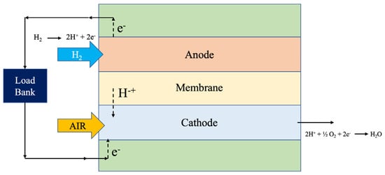
Figure 1.
Schematic diagram showing basic components of PEMFC. Adopted from Dhanushkodi et al., 2013 [12].
The importance of PEMFCs is in the generation of hydrogen energy for transitioning to a sustainable and green energy future. This source of generating energy provides a clean alternative to fossil fuels, significantly reducing greenhouse-gas emissions. Hydrogen as an energy alternative can be produced from various renewable sources, ensuring energy security and diversity. Additionally, hydrogen fuel cells offer high efficiency and quick refueling times, making them suitable for a range of applications, from the transportation sector to stationary power generation. Guan et al., 2023, [15] performed a detailed techno-economic analysis to estimate the cost driver in green hydrogen production and the variations in electricity prices based on the hydrogen flows across the channel, providing the physiochemical properties and structural features of cell components such as the flow field. The effective delivery of the hydrogen across the catalyst layer improves the productivity of the cell and establishes a need to select a suitable flow-field design to improve the hydrogen economy.
2. Design Requirements of Bipolar Plates
Several key specifications need to be considered in designing the BPs for PEMFC, such as transport current, gas distribution, water removal, mechanical stability, cooling, cost, etc. A primary requirement for BPs is the effective transmission of electrons from one electrode to the other through the plate. This necessitates regions of low contact resistance and a plate material with low electrical resistance to enhance fuel-cell performance [16,17]. The design also must consider uniform current distribution, since non-uniformity can lead to accelerated erosion of the BP and the MEA. Another essential aspect is the distribution of gas; the entire reaction region requires a consistent supply of hydrogen and oxygen to sustain the electrochemical reaction. The process must maintain a low-pressure drop even at high gas-flow rates to enhance efficiency. The configuration, channel design, and stack manifold design must account for better flow and mass transfer to the catalyst surfaces while minimizing the pressure drop. A small pressure drop ensures sufficient flow through the GDL to the catalyst surface, reducing mass transport losses. A major challenge in fuel cells is water management; the PEMFC design has to determine where liquid water accumulates and how easily it can be removed. Water in the fuel-cell stack can affect the overall operational performance, pressure loss, and start-up delay. The electrode plate configuration must facilitate liquid removal under various gas-flow conditions, enabling operation at low flow and low temperatures across various conditions.
Additionally, mechanical reliability and cooling of the BP are critical challenges to assess. The BP must be mechanically stable to reduce contact resistance, maintain necessary compression pressure for cell closure, and withstand varying media pressure [2]. Proper material selection can prevent cell degradation under several conditions. The interface between the BP and the other components must effectively dissipate the heat to the cooling system, as fuel-cell operation generates significant heat by exchanging with the exhaust gas rather than the coolant. An improper design of components can generate local hot spots, resulting in drying or breakdown of the MEA or early failure of the membrane and BP. Hence the design must ensure a uniform cooling distribution to avoid overheating and maintain cell temperature control. Issues relating to flooding and hot spots can be solved by the constructive design method of the coolant and reactant flow channels [18].
Subsequently, the cost, weight, and material requirements are important considerations. BPs should be less expensive and lightweight, with a minimal manufacturing cost. Material choices like carbon-based materials or metals and stainless steel will offer inherent features that influence the design. The selected material must have good manufacturability, thermal conductivity, corrosion resistance, and electrical conductivity. These requirements are dependent factors that cannot be separated and are strongly considered in the design stage of fuel cells [19,20,21].
3. Flow-Field Design
Bipolar plates in PFMFCs play a crucial role by maintaining the MEA and thermal, electrical, and physical connections. Being a part of bipolar plates facilitates the multiple functions in PEMFCs. A PEMFC performs the task by processes carried out on both sides of a half cell in the bipolar plates. The bipolar plates transport the fuel and oxidant to the reactive sites, collect the generated current, remove the reaction products, and aid in cooling. Additionally, bipolar plates also protect the cell from the mechanical stress produced and help in water management [22]. The type of bipolar plates, mainly the gas-flow channels, which are part of the healing system, have a huge effect on the performance of a stack, both in the long and short term [23]. Various evaporator designs have been developed and could be implemented in different conditions. They all have unique features that could benefit or not work under several operating conditions. Many inventions are depicted in the literature from prehistoric times to the present, which is the main theme of this review.
3.1. Pin-Type Flow Field
Coming to designs, a particularly old and customary type is the pin design. Here, the pins will be arranged in a precise manner, forming the stream-field net. As for the shapes of these pins, usually, they can be square or round, but cubes and circles are the most commonly used in practice, as shown in Figure 2. Typically, both flow-field plates of the cathode/anode contain arrays of regularly spaced V-shaped pins that are perpendicular to the plate while the reactant gases flow across the plates through the grooves between the pins. Thus, there is a path for a real fluid flow on several series and parallel flow channels. The second reason is the frictionless and low reactant pressure drop in the pin design flow field. Compared to the product water, the reactants moving through the turbulent flow fields do not fight the resistance force at some intervals. They make the flow pass through the channels, forming stagnant regions, which can lead to inefficient reactant distribution and inadequately distributed water products [24,25].
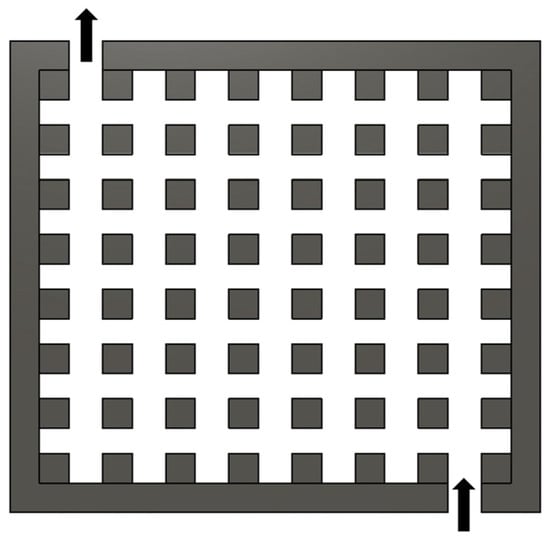
Figure 2.
Pin-type flow field. The design is adopted and redrawn from [23,24].
In their research, Guo. N., et al., 2013, [26] stated that the next step would be network-based model optimization of pin-type flow-field design would be conducted. The pin-type flow field has the advantage of low-pressure drop compared to the other designs. These designs experience issues of uneven flow distribution and dead zones. The related optimal designs were created for two optimization cases: uniformity of flow divided and non-divided in the case of reactant being consumed on the way along the flow channels. The tabular contrast of the original pin-shaped reservoir with the improved ones recorded much better fuel-cell performance by a significant margin. In addition to this, the optimized design illustrated in Figure 3 shows that embodied reactant consumption performed better than the one that did not, thereby demonstrating the role of reactant consumption in the model of flow-field optimization [26].

Figure 3.
Optimized pin-type design. The image is reused from [25].
Dong-Hui W, et al., 2017, [27] offered a forward-looking pass over of the plural plate in metal bipolar form for PEMFCs. Bionics, fractional theory, and Murray’s law created a new hydrodynamic surface to cut the drag force caused by the reaction fluid and the product flow. Through bionics and fractal theory, the field of flow leading to the cross structure was designed, which is harnessed for sustaining the transmission capability. At the sharp turns, Murray’s Law was utilized to calculate the angles. Bipolar plates made of stainless steel with flow-field intersection are machined by an electronic discharge machine (EDM) and were used in tests. To begin, the bipolar plate was coated with a specific material. The numerical simulation of computational fluid dynamics (CFD) has been used to analyze which is better between the serpentine and intersectant flow fields, as illustrated in Figure 4. Consequently, the computational study of a new flow field revealed some advantages over the serpentine flow field in distributing the reaction substrate and maintaining the exhaust of the reaction product uniformly. Moreover, the polarisation detailed the higher efficiencies of the novel flow field. The experimental results verified that a reliable novel flow pattern enhanced the performance of PEMFC [27].
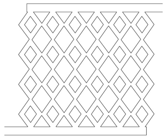
Figure 4.
Novel intersectant flow channel. Image is adopted and redrawn from [26].
3.2. Series-Parallel Flow Field
As Deepra Bhattacharya et al. [28] pointed out in their study, forming a straight-line canal is very simple, as it is a fill figure design with regular symmetry. Fast and simple operations, easy process control, and low noise level are the essential pros of a straight flow. A major drawback of the shape is that particles stay in a straight channel for a minimal duration, resulting in decreased fuel/oxidant utilization. Concerning the serpentine channel, one can state that the long residence duration of fluid particles is directly related to the curve that may be single, double, or twisted and with the larger flow channel. Hence, the percentage area of the effective flow rate is supposed to have undergone a rise together with the number of fuels and oxidants used [24]. Accordingly, the effect of the comparison, with modified and conventional parallel flow fields, is illustrated in Figure 5 and Figure 6, predicting the modified parallel flow to attract more reactants than straight/parallel flow [29]. The channel was split into phases, each allocated the same amount of flow to ensure that the flow direction on the modified field was equal. The reduction of entry- and middle-channel widths was followed. The area of the channel was widened at the tip of the channel to induce sufficient pressure drop, to ensure uniform flow distribution and water purging. According to the simulation data, a new parallel flow pattern may result in flow equalization and progressive pressure fall from the intake to the outlet as the flow moves along the tube. The whole active field of the PEMFC is used for this, so a balanced distribution of reactive and pressure in the flow field, whereby the performance is enhanced, follows. Since the particular single inlet–outlet design with the 1 mm channel region is the same as the other design, the single inlet–outlet system worked much better than the double inlet–outlet system. The two flows, however, were not the same for the double inlet–outlet since the lengths of the channels differed. The main reason for non-uniform flow patterns in a straight channel is the irregularity in the channel length scan which, in turn, produces a uniform flow distribution through a single inlet–outlet [30,31].
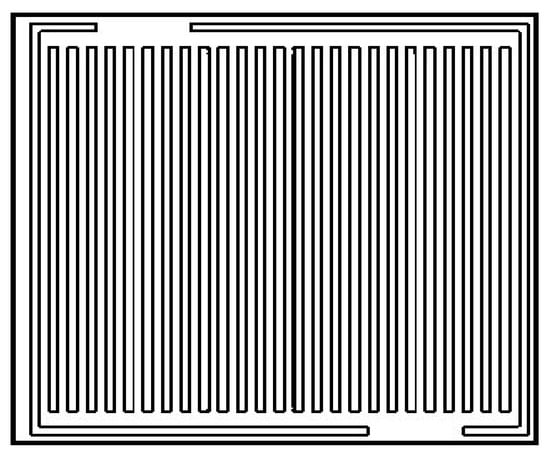
Figure 5.
Straight and parallel flow field. The image is reused from [32].
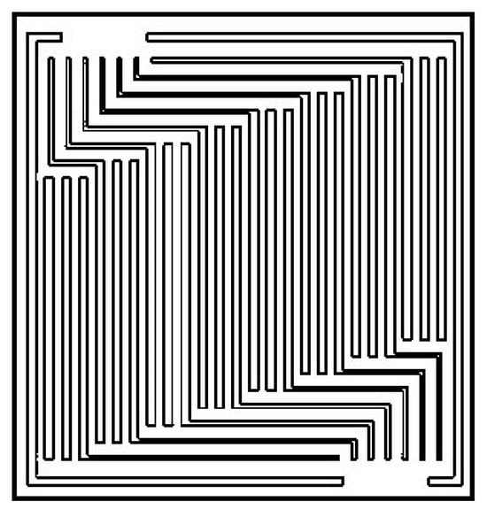
Figure 6.
Modified parallel design with multi-path flow. The image is reused from [30].
Sajid Hossain M., et al., 2017, [33] studied improving the homogeneity and hybridization of the cathode air in the parallel channel flow domain in the fuel cell. This research was conducted with 2D CFD analysis using Ansys 15.0. Two major designs were investigated: (1) Z type and (2) Z and U type, or a combination of these two parallel channel topologies. In the z-type flow with parallel channels, the study results indicated that nonuniformity increases with channel width. Contrasted to the other two widths, a width of 0.5 mm offers markedly improved the uniformity of flow distribution through the flow field. Globalizing the narrow width of the header throughout its entire length is an effective method for intensifying the lateral channels within the center of the flow field. Compared to the standard type of design, only 60–70% of the total flow was released, and 80% of the total gas flow was observed under the frontal area, which was reversed. Bringing the two configurations of the Z and U types in a parallel channel flow field may not perform as well in comparison to other layouts; still, it certainly gives a better flow distribution compared to that of a typical parallel channel flow field. At the same time, lower-scale modifications, as shown in Figure 7, perform better than traditional parallel designs [33,34].
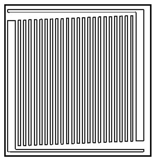
Figure 7.
Modified parallel design with a gradual decrease in inlet channel and increase in outlet channel [33].
3.3. Serpentine Flow Field
The basic serpentine model resembles a constantly running single channel that goes through the entire flow-field pattern (FFP). By combining the input and outlet, the reactant gases enter the fluorinated ethylene propylene (FEP) and go through the under-rib channels on the FFP. The serpentine heat exchanger has strong performance which is why it is used as the typical design in the industry. It serves the purpose of a baseline for a new, upgraded, or any forthcoming FFP system. Although liquid water will flow to the downstream channels and the bends are short, the serpentine layout prevents flooding by facilitating the free-flow transportation of the liquid. This can be achieved by using a relatively high-pressure drop through a porous medium to expose a gas to it [35,36].
Along with this, Limjeerajarus N., and Charoen-Amornkitt P., et al., 2017, [37] propounded a mathematical analysis of the flow field by considering six different designs of 1S, 3S, and 5S-serpentine shown in Figure 8. Parallel in series, 3PIS, and 5PIS are shown in Figure 9. The research revealed that flow-field design was one of the key factors in the energy-conversion efficacy and hydrogen transport of PEMFCs [37]. Hence, membrane hydration uniformity was a maximum in the 1S flow field and a minimum in the parallel flow field. Correlating to the uniformity of the membrane, PIS flow fields showed mildly better behavior than the multi-channel serpentine flow fields (SFF). Regarding the uniformity of hydrogen distribution, the former was quite better than the latter, whereas the effect of parallel flow was not up to the mark. The cyclone-separated flow caused a non-uniform distribution because of the solid-wall region, whereas the 1S flow gave the best uniform distribution. Therefore, mechanical stress from non-uniform heating and water discharging was more likely intensified by the parallel systems. The authors concluded that flow systems with minimum channels enhanced homogeneity and satisfactory cell performance concerning small-scale polymer electrolyte fuel cells (PEFC). On the one hand, the channel number has a much higher overall effect on the performance of small-scale PEFCs than the geometry of the FF layout. However, on the other hand, the impact of configurations confirms the previous studies once the number of channels increases. Moreover, the parallel in-series flow fields provided better uniformity and water management than the multi-channel serpentine flow fields for only the same number of channels. In addition, the higher reaction velocity was not a drawback, because of the shape of the FF [38,39].
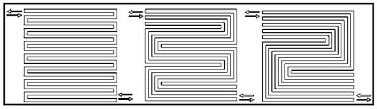
Figure 8.
1S, 3S, 5S Serpentine flow field [37].
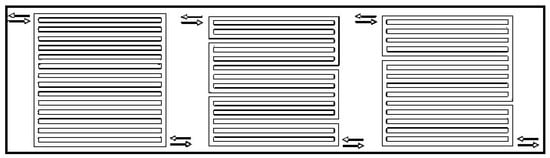
Figure 9.
Parallel, 3PIS, 5PIS (parallel in series) serpentine flow field. Image is adopted from [37].
Nam JH., et al., 2009, [40] in the present research, offer an approach for creating a micro-porous substrate flow field (MPSFF) with single and parallel-path flow fields MPSFFs in a single microchannel for PEMFC applications. MPSFF strategic arrangements of multipass corridor networks enable the placement of channels with quite different lengths nearby. The ultimate path-length disparity in neighboring flow channels caused by this operation is intended to promote under-rib convective transport, and as a result, enhance the PEMFC performance. On the other hand, the elaborately braided MPSFFs’ hoops are suggested to improve the local uniformity of the reactant, product concentrations, temperature, and liquid water content through the active cell region. MPSFFs are projected to save costs for those small fuel cells in portable applications. MPSFF, having a more under-rib convection process, generally contributes to the drop in pressure across PEMFCs, resulting in a performance gain by reducing the power consumption of air blowers in mobile-powered systems [39]. Existing configurations for three-path MPSFF with three pass patterns and five pass patterns are illustrated in Figure 10a,b. A similar configuration, with a five-path MPSFF with a three-pass and nine-pass pattern, is shown in Figure 10c,d. Other benefits of MPSFFs in PEMFCs are the more uniform distributions of reactant concentrations, temperatures, and water saturation, allowing for automatic PEMFC operations on cylinder gases with internal humidification. Furthermore, the purpose of MPSFFs is to optimize the current PEMFC temperatures.
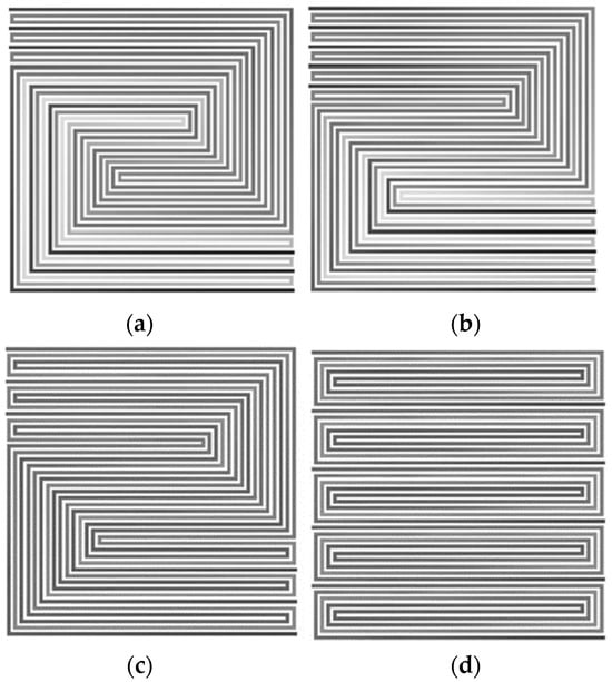
Figure 10.
Path configurations for MPSFF [40]: (a) 3-path MPSFF with 3-pass patterns, (b) 3-path MPSFF with 5-pass patterns, (c) 5-path MPSFF with 3-pass patterns, (d) 5-path MPSFF with 9-pass spiral patterns. The images are reused from [35].
Arun Saco S., et al., 2016, [41] in their paper, came up with a comparison of varied serpentine flow fields, such as straight zigzag, straight parallel, serpentine zigzag, and serpentine parallel. We identified that higher power density and current density corresponded to the zigzag pattern. Straight zigzag is illustrated in Figure 11, i.e., 0.3758 W/cm2 and 0.9396 A/cm2. In contrast, the minimum corresponded to the serpentine parallel, i.e., 0.0662 W/cm2 and 0.1655 A/cm2. The reduced current and power densities for serpentine parallel and straight parallel achieve efficiency due to the slower reactant consumption, even though the oxygen consumption is optimal. The core channel, comprising a zigzag straight conduit, ensures the optimum current and power densities compared to the other flow channels [42].
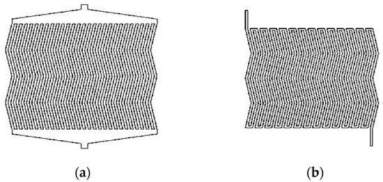
Figure 11.
Zig-zag flow-field design with (a) PFF and (b) SFF Images are reused from [41].
Zhang, J., et al., 2013, [7] studied the SFF-PEMFC performance in terms of different geometrical channel parameters (channel length and different combinations of channel width and depth), and also assessed the particular current density (porosity, temperature, and inlet speed) on the system performance. Of course, the drainage performance, gas transportation channels, and electrical properties were among the indicators to evaluate the performance. The following is the summary of key findings: When the constant defined length of the FF remained studied, it supported that the eight-channel lengths in SFF and the eight-channel long with complex patterns were in the optimum range, considering the qualities of distribution along the gas line, water, and pressure channels, as well as of electronic activity. An eight-channel complex SFF can achieve optimal liquid drainage and fluid distribution when its width is 1.2 mm and depth is 0.8 mm. The channel 1 to 10 complex SFF is presented in Figure 12a–h. It is mostly the GDL porosity that has a significant effect on water, current density, and the amount of oxygen present in SFF-PEMFCs [7]. Ss for intake speed and temperature, they do come next [8].
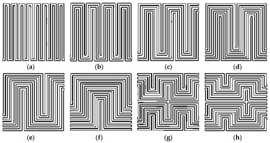
Figure 12.
Different channel design for SFF [8]: (a) 1-channel SFF; (b) 2-channel SFF; (c) 3-channel SFF; (d) 4-channel SFF; (e) 5-channel SFF; (f) 8-channel SFF; (g) 8-channel complex SFF; and (h) 10-channel complex SFF. All images are reused from [8].
In their paper, Jin CK., and Kang CG., 2011, [43] sought to find the SFF. The serpentine flow channel design ensures that water is drained in the flow along the channel, while the pressure drops are a reasonable consequence of excellent cell performance. The appropriate contact surface area on the flat channels for serpentine channels may be enhanced by square curves, since the square curves have always shown lower resistance than curvilinear channels [43].
Kim A., and Shin S., et al., 2016, [44] in their research, studied contrasted serpentine and straight-stream configurations. The calculated total pressure loss is minimal in the serpentine flow channel design compared to the straight channel. In general, most of the reactants entering the BP channels follow the channeled path constituted at right angles to the pitch depth, where the driving force of mass transfer mainly passes through the mass concentration difference, as in the straight path case, because the convective flow is not that remarkable. Contrastingly, serpentine flow streams are subject to several 180-degree reversals that can be traced back from the intake to the exit point of the channel thus causing secondary convection through a porous gas diffusion medium (GDM) [45]. Therefore, M. Rahimi-Esbo., M., et al., 2020, [46] proposed the impingement upwind technique (IUT) to improve the quality of temperature uniformity on bipolar plates. They fixed three serpentine cooling flow-field linings and applied a constant heat flux to the cooling flow field’s wall. They reported that the serpentine layout had decreased the IUT more than the parallel design.
Alfedo Iranzo, et al., 2020, [47] in their study, showed that the serpentine pattern had a fairly good performance in water drainage. Still, the situation was similar with various serpentine channel forms, where reactants were depleted or exhausted. The literature showed that the flow field profoundly influences cell efficiency at low operation potentials. The coiling and interlocking flow channel design extracts more water and distributes it uniformly. However, its high-pressure drop and unequal reactant distribution also constitute disadvantages. Static zones might be produced by different flow-field designs, such as, for example, perpendicular and pin ones due to non-homogenous uneven water discharge.
In summary, various flow-field geometries are employed in the literature to optimize the fuel cell. Each geometry exhibits unique merits and demerits for enhancing the PEMFC performance. Table 1 provides a comprehensive summary of the geometries mentioned above, provided with research needs and potential improvements of individual flow-field geometries.

Table 1.
Summary on the geometry flow field.
4. Bio-Inspired Design
Bio-inspired fluid flow designs mimic natural patterns, enhancing efficiency, performance, and water management. Ouellette, et al., 2018, [48] studied the reason why the serpentine flow field and bio-inspired interdigitated and non-interdigitated flow fields for anode and cathode sides yield higher performance are explained, the configurations are illustrated in Figure 13a–c. When the bipolar plates with non-interdigitated flow areas were used as an anode and cathode flow field, the number of exchanged electrons and ion transport was maximum in proportion to the reduction in cell stress, but also the least among all approaches. Simulations showed that the coil on the anode and the cathode gave the best result with serpentine and interdigitated flow fields. Due to the up-rib convection enhancement, the S-S serpentine and S-I serpentine designs showed better reactant homogeneity over the catalytic layer (CL). However, if the first-generation and/or second-generation branch of the nanostructure is leveraged, the interdigital flow field might be improved. On the other hand, pressure drops between neighboring branches are huge enough to avoid almost any zones of dead reactants or harmful products. The aim is to decompose the reactants at a slow pace, so as not to evacuate the collector channels too much, which leads to voids beneath the collector channels. Therefore, special design considerations for the collector channel are needed.
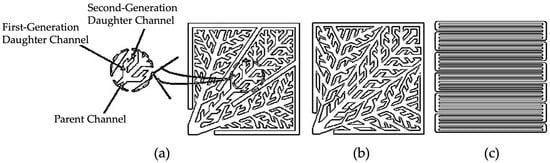
Figure 13.
The FF configurations [48] (a) interdigitated FF I-configuration, (b) non-interdigitated flow-field configuration, and (c) serpentine flow-field S-configuration.
Ozden. A., et al., 2017, [49] investigated the effects of different flow fields’ straight channel configurations with different channel dimensions (L1 and L2), serpentine flow-field design (LG), and interdigitated flow field channel (S) configurations on the direct methanol fuel-cell (DMFC) performance. Instead of natural offshore bathymetry, Murray’s Law was employed to determine the channel geometry in the L1 and L2 flow-field layouts. Out of these having fourteen distinct configurations, seven are found after the intended flow-field configurations are fabricated. Performance tests conducted at 70 °C with the S-L2 flow-field arrangement produced the best results at methanol concentrations of 0.50M and 1.00M. The highest peak powers of the S-L2 and S-S are noted at 888 W/m2 and 824 W/m2, respectively. When the other designs were compared, the LG-based flow fields were not able to perform as well as the others. Among those liquid-metal flow fields with bio-inspired patterns, as presented in Figure 14a–d, the ones that use the cathode of the supercapacitor produced the best results. Numerically, the designs showed the best performance at the highest-level rates of methanol and oxygen, both at the maximum flow rates of 3.9 mL/min and 1200 mL/min, respectively. In a 1M methanol solution, all of the given flow fields reached their maximum power densities in the final configuration. The L1–S design was unusual since it performed well at a methanol concentration of 0.75M. However, the bioinspired flow-field plates showed low performance improvement, as per observational reports. Also, the latter one has an L2 AFF and can be said to have performed rather worse than its counterpart the serpentine AFF in terms of the traditional design. Contrarily, the L2 convectional flow field (CFF) has a superior result to the serpentine CFF. Alternatively, exploiting the DMFC with the zigzag configuration enhances its efficiency. The idea is to explore fresh bio-inspired flow-field configuration settings for further enhancements using optimization studies [49,50].
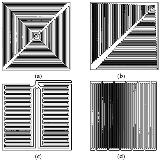
Figure 14.
Different configurations of bio-inspired FF: (a) the first bio-inspired leaf flow field, (b) the second bio-inspired leaf flow-field configuration, (c) the bio-inspired lung flow-field configuration, and (d) the Serpentine flow-field configuration. Image is reused from [49].
Ghadhban, S., A., et al., 2021, [51] evaluated the geometric effects of flow fields, such as the design and size, to determine their impact on the efficiency of PEMFCs, since they transport gases to reactive sites, effectively removing reaction products and serving as channels for electrons in the electrical circuit. Herein, the current study is an experimental exploration of the effectiveness of bio-inspired flow-field topography on the performance of the PEM fuel cell. The PROTIUM-150 used in the research uses six cells, reaches a rated power of 150 W, has a voltage range of 15 V to 23 V (10 A), and has an active area of 9.84 cm2. Two novel structures (i.e., leaf veins and tree form) inspired by biological systems are offered. Inside the bipolar plates, where the flow fields are contained, metal is used [52]. The suggested fuel cell’s performance can be assessed by measuring the resulting power and polarization curves and comparing them to those obtained for a fuel cell with a single-channel flow field. The findings suggest that the bio-inspired leaf-veins-type flow field increases the PEM fuel-cell performance. It has a 5.12% stronger position among serpentine designs and a 3.75% better position among tree-shape designs [50].
Roshandel, R., et al., 2012, [53] demonstrate that the design of the flow channel of the bipolar plates greatly influences the performance of the PEMFC. Various parameter modifications, such as channel type, shape, or size, tend to increase the power of the turbines. The modeling is conducted in a three-dimensional steady-state form and a multi-component model using experimental data. The method of this study is composed of the use of a CFD analysis to scrutinize the flow field’s varying geometries. The usage of bio-inspired structures is described, and its pros and cons are compared using a numerical model with the preceding design method of bipolar plates. Fuel-cell performance indicates a tendency toward an increase, as predicted by simulations. The designs with the nature theme are the ones facilitating more suitable species and velocity distribution of an object flowing in a channel as inferred. Further, it is proved that the proficiency of the acquired amount of voltage and power density would be increased. For the investigated BI bipolar plate, the power density can be increased by 56% and 26% if compared to other commonly used flow channels, such as parallel flow and serpentine flow. What the results of this experiment showed was that, by applying this revolutionary new design, we have the capability of making fuel cells that are extremely efficient, as well as inexpensive and lightweight. Yet, this model is not the best bipolar plate ever designed for PEMFC. But, irrespective of that, this is the first effort to develop new innovative models to enhance fuel-cell efficiency [53,54,55]. The key findings of the bio-inspired fluid flow design are presented in Table 2.
Table 2.
Literature summary on the bio-inspired flow field.
Asadzade M. and Shamloo A., 2017, [56] showed that the optimal design for a bipolar plate was the one with a mesa profile. This opens up opportunities for improved flow design in the bipolar plate that matches the cell scales to reduce the pressure drop of the reactants as the novel lung-shaped flow pattern, and it has a 15% lower pressure drop compared to the traditional parallel serpentine flow pattern (PSFP), as shown in Figure 15. He observed that the pressure dropped as much as 38 pa, which is higher than that of the novel lung-shaped design. The main reason behind it is that it involves dramatic changes in the flow direction along the circus and fork channels, causing a considerable head loss, which is compensated for by branching in the planar design. On the other hand, in the bio-inspired design, the flow path of corollas with a 135° angle creates up to a five times reduction in the pressure loss. A center-piece lung-shaped bipolar plate of the polarization curve indicating upon elicited considerably high values may unveil an increase of up to 100% in the device’s performance. The only drawback is its costs, and it takes lots of time to manufacture a bipolar plate in a lung shape. However, it is supposed that, as manufacturing processes advance, the cost and time of producing lung-shaped bipolar plates will lower, and it will become cheaper to manufacture them for mass production [56]. Table 3 shows the comparison of the different flow fields in the anode and cathode [57].
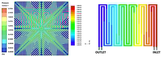
Figure 15.
From left to right: pressure distribution contour within the anode of the fuel cell having lung-shaped bipolar plate and pressure distribution contour within the anode of the fuel cell having dual serpentine channel bipolar plate with square bends [56,58].
Table 3.
A Comparison between concentration loss for different flow fields in the anode and the cathode sides of the fuel cells [56].
Hie Chan Kang et al., 2019, [59] determined that liquid, while running the 353 K of each respective type of fuel cell, had 100% relative humidity and 101 kPa output air pressure. For the SFF, the current density was the highest at 1200 mA/cm2, then 709 mA/cm, followed by 1158 mA/cm2 for ginkgo and 894 mA/cm2 for the leaf with 300 Mv. On the low-current zone, the ginkgo flow region saw a rise in voltage to around 450 mA/cm2 with their SFF losing a surge in maximum voltage. By measuring the leaf flow phenotype value from the net-flow field (NF) and the spares-flow field (SF) by using the ginkgo leaves field and the low current field (i.e., 500 mA/cm2), the results show that the Myriophyllum SF presented the greatest water yield value, followed by the ginkgo flow field, while NF had a different leaf flow density value with the low J-parallel field. Based on such data, the suspension–tension ginkgo field will be, obviously, above the ranges of parallel flow and net flow. The water-removal capacity in the serpentine domain was the largest, but it was the lowest in the plane of net leaves. Moreover, the ginkgo transport ability was relatively higher than the removal value of the rainwater flow parallel field. Finally, the water evaporates during a longer unit run [59].
As Kloess JP., et al., 2009, [60] discovered that the pressure drop was the best in the leaf and lung design patterns, while in the sole simple serpentine and interdigitated types, it was worse. Pressure drop results in this spiral configuration and an interdigitated design are seen to be closely comparable. The same fate does not befall the leaf and lung designs because they all make more low-pressure areas and supply gas consistently to the GDL. A cut view in the middle of each flow pattern design was utilized to identify the target pressure and velocity profile. In both the leaf and lung mechanisms, the velocity will be lower, but it will be evenly low. Additionally, leaf and lung types cause almost no rate of pressure loss in the flow direction, but it is pronounced in the serpentined and interdigitated forms. Now, there is a possibility to check the ‘up’ effect using the new leaves and lung design and then affect the fuel cell. As the temperature rises, the new leaves and lungs get better results. The above-mentioned acceleration of performance is at the highest level between 65 °C and approximately 75 °C only but decreases progressively at the test temperature of 85 °C. The first possibility is that, when the temperature is over 75 °C the gas line dry hot water does not provide enough humidity for the MEA but, on the contrary, dries it up and affects its performance. The cloth pattern and the recurrent clockwise trim increases the relative humidity. The membrane’s hydration level remains high, while the free-radical oxidant that this membrane contains facilitates the electron transfer from the anode surface to the electrode on the cathode side. When it bounces, the membrane experiences a mildly resistive phenomenon as the humidity increases. Inversely, a humidity increase coincides with a rise in current density. On the other hand, in water-abundant areas, where the high current demand has been met, people are not ready to swallow a price increase anymore. When there is a water accumulation, however, the maximum peak power density is attained at 100% humidity; it dominates as the best condition for this function. The more the leaf or lung architecture facilitates this improvement, the more the pressure rises. This effect is clearer when a back pressure of 0 atm is compared to a back pressure of 1 atm, but it is not as obvious when the pressure difference between 1 and 2 atm is considered. This design is in line with the interdigitated channel structure, which is the basis of fuel-cell generation. The serpentine, interdigitated, leaf, and lung designs are evaluated under identical working conditions, namely 2 atm pressure, 75 °C temperature, and 100% relative humidity. In contrast with the serpentine and interdigitated ones, these new varieties offer a higher performance and power density maxima of up to 30%. The highest rate is demonstrated by the leaf design compared to the lung, interdigitated, and a single serpentine [61].
Trogadas P., et al., 2018, [61] reported that the lung has a similar function in nature; it takes air from the atmosphere and subsequently conveys the air into the bloodstream through its fractal architecture and dissolves the air into blood cells. In the self-similar or fractal geometry that follows Murray’s law, each bifurcation of a parent vessel is cubed and added to a sum of cubes of diameters of daughter vessels resulting in minimum mechanical energy losses of two networks. It is right that the lung structure naturally contains this branching fractal statistics, and thus, it ensures the uniform distribution of oxygen within the given quantity. As the bifurcating branches parent, and with the slower gas flow from the bronchial (convection-driven flow; 7–9 lower generations) to the acinar airways (diffusion-driven flow; 7–9 lower generations), all the local entropy production [23] (entropy production in both regions) is minimal overall globally [24], rather than global entropy production in the whole structure. Thus, the criterion of thermodynamic optimization is the rigorous linkage between the value of resistance pressures in the lungs and their consistency with all branches, as shown in Figure 16a–e. The difference in motions within the bronchial and acinar airways (the extent to which both are separately governed by convection and diffusion) characterizes another main peculiarity of the lung unless its airflow is treated as a fractal. As new generations of fractal flow fields are added, this simultaneously spans longer and shorter scales within the system without any change of its main constituents or microscopic mechanisms. The flow-field geometry of the conventional serpentine pattern electrochemical fuel cell (EFC) is compared to that of the larger scale, 3D-printed models that embody a fractal double-helix geometry (25 cm2 surface area) with N = 4. The pressure drops of around 25 KPa for the serpentine flow-field-based PEMFCs have large channels compared to the fractal channels contributing to the linearized polarization curves of both cases, due to which they follow a similar trend [61].
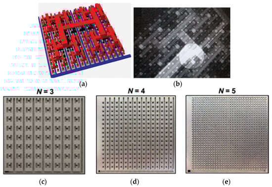
Figure 16.
The promising modeling results guided the engineering of lung-inspired flow fields. All images are reused from [61]: (a) 3D network of the inlet (red) and outlet (blue) branches used in these flow fields; (b) X-ray radiography is employed to inspect the flow fields for structural defects; (c) the engineered FF with N = 3; (d) FF with N = 4; and (e) FF with N = 5.
5. Circular Geometry
A radial flow-field design was developed using an annular, tablet-type PEMFC [62]. The reactants are introduced through a tube at the center of the circular area and are transported to the outside through radial channels. The radial channels in some designs are connected to the circumferential ones to keep the pressure drop equal through the channel length [16]; the number of radial chambers can be adjusted accordingly. CFD analysis of the radial flow topology with four, eight, and twelve radial channels revealed that the four-channel system had the best performance and the highest current density attainable, with the lowest pressure drop throughout the system, as shown in Figure 17a–d [63,64,65,66].
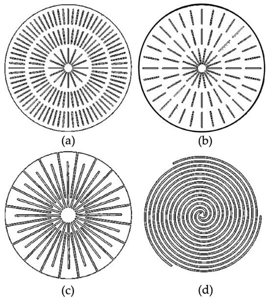
Figure 17.
Sketches of radial designs with 16-48-72 [35] (a) and 18-24-32; (b) radial and 2 circular channels, with 20 pairs of radial interdigitated channels; (c) from [64] 3-channel spiral design (d), from Juarez-Robles et al., 2008. Images are reused from [66].
5.1. Geometry
Mechanical stability, temperature distribution, water removal, reactant flow rates, pressure drop, and electrical conductivity of the stack are all significantly impacted by the size of the channels and the lands that separate them. The dimensional specification of the channel/land is illustrated in Figure 18 [67].
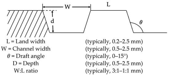
Figure 18.
PEMFC channel/land design features. Image is adopted and redrawn from [66].
5.2. Flow-Field Cross-Section
The fluid flow channels are typically rectangular in cross-section. However, alternative shapes, including trapezoidal, triangular, semi-circular, and others, have been studied. The anode’s hydrogen concentration rises as the land width decreases; in contrast, the land width of the hemispherical and triangular cross-sections is almost nil. In practice, the MEA may be compressed at high-pressure contact zones by a triangular or almost zero land width design, which would impede current collection [16].
The form of the channels affects the amount of water that builds up in the cell, which in turn, affects the reactant flow rates. As can be seen in Figure 19, tapered channels promote the formation of discontinuous water droplets, whereas circular channels promote the generation of a continuous film of water. Reactant supply and distribution are enhanced because discontinuous water droplets are easier to break and remove [67].

Figure 19.
Water accumulation in tapered and circular channels. Image is adopted and redrawn from [67].
Three different channel cross-sections (rectangular, trapezoidal, and parallelogram), as shown in Figure 20 with the same channel height and area, were discussed by Ahmed et al., [68] guaranteeing consistent boundary conditions in every case. Simulations comparing both channel designs showed that the trapezoidal channel cross-section delivered more uniform reactant and local current density distributions at the membrane–cathode GDL interface, whereas the rectangular channel cross-section provided larger cell voltages. Additionally, the results showed that, at low current densities, the rib width had little effect on the cell operating potential, but it had a significant influence on the cathode overpotential and Ohmic loss.

Figure 20.
Cross-sectional view of different geometrical configurations analyzed (images are adopted from [68,69] and not drawn to scale): (a) rectangular; (b) trapezoidal; (c) parallelogram.
Ahmed DH., and Sung HJ., 2006, [68] addressed three distinct analyzed channel cross-sections, as shown in Figure 20 and Figure 21 (rectangular, trapezoidal, and parallelogram) with the same channel height and area, ensuring uniform boundary conditions in each instance. In contrast to the rectangular channel cross-section, which produced higher cell voltages, the trapezoidal channel cross-section generated more uniform reactant and local current density distributions at the membrane–cathode GDL interface, according to simulations comparing the two-channel designs. Furthermore, the outcomes demonstrated that the rib width significantly impacted the cathode overpotential and Ohmic loss but had minimal effect on the cell operating potential at low current densities.
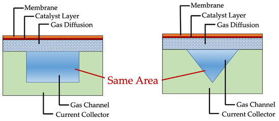
Figure 21.
Cross-sectional view of analyzed channels. Both images are adopted and redrawn from [68,70,71].
5.3. Tapered Section
The tapered shape provides superior performance at high current densities, compared to a standard design. Because of their high water-removal efficiency, tapered flow fields have an advantage in oxygen mass transfer. First, by increasing the gas-flow velocity in the exit region, tapered flow fields can eliminate accumulated water in forced convection channels, as shown in Figure 22. Second, by strengthening under-rib convection between nearby channels, the tapered design helps to minimize the difference in oxygen concentration between the rib and channel regions by encouraging the evacuation of water accumulated in the under-rib area of the GDL. Clear details of the flow field are given in Table 4. Furthermore, when constructing a flow field to balance the pressure drop and cell performance, the operating range of current density should be considered because a higher-pressure drop would increase water removal while increasing parasitic power loss [72]. The experimental results of the different flow fields are given in Figure 23.
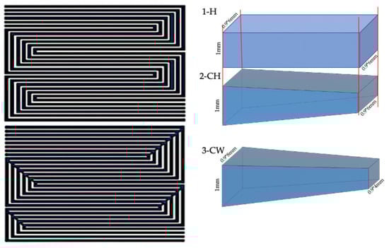
Figure 22.
Flow-field patterns design dimensions of a tapered shape. Images are redrawn from [72].
Table 4.
Details of the designed flow fields.
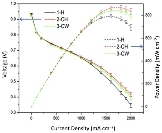
Figure 23.
The experimental results of cell performance at H2: Air = 1.5:2.0 with three different flow fields at 80 °C, 100% RH, and 150 kPa back pressure. Image is enhanced and redrawn from [72].
5.4. Channel Width and Land Width
The plate’s flow channels are made to carry reactants to the MEA and evacuate surplus water, and the area in between them is meant to carry heat produced by the electrochemical reaction as well as to collect and distribute current between the cells. In other words, a big bandwidth offers strong electrical and thermal conductivities, as well as mechanical stability, and a large flow channel width enables efficient reactant supply and water removal [73].
Reducing the land width and expanding the gas-flow channel width improves the mass transfer of the reactions to the catalyst layer. Even the distribution of current across the cell is guaranteed by the broader channel. However, the broader channel is where the temperature peaks result in the creation of heat-generating zones in locations where electrochemical activity is high, particularly on the cathode side [74].
The impact of different land-to-channel ratios on the performance of serpentine flow fields in PEMFCs is examined by Shimpalee S., and Van Zee JW., 2007 [75]. The most uniform temperature distribution and consistent current distribution across the MEA surface are produced by designs with a land-to-channel ratio greater than unity. On the other hand, the layout where the land-to-channel ratio is less than unity results in a significant amount of non-uniformity in the distribution of temperature and current, which affects the durability of the materials.
The effect of different land–channel ratios is given in Table 5. When the channel-width-to-rib-width ratio is kept at 1:1, a wider channel results in generally worse cell performance. A large flow channel accentuates the unequal distribution of RH and oxygen content. As a result of the water buildup, this results in flooding and raises the cell RH. A higher ratio boosts cell performance, but only until the ratio falls below three. After that, it starts to decline. The narrow waterway and wide rib impede both mass transport and water discharge [76]. The results indicate that channel width affects the pressure drop more than the land width. Total cell efficiency decreases when the channel width decreases because of the increased pressure drop. Conversely, the pressure drop is mostly unaffected by land breadth [77].
Table 5.
Effect of different land–channel ratios [68,70,75].
The electrochemical reaction rate increases when the cell is operated at a lower voltage, which increases the production of water. Different contours of the current density distribution are presented in Figure 24. Therefore, if the aspect ratio (W:d) decreases, the cell performs better because the reactant input flow velocity is improved, liquid water removal is improved, and oxygen transport to the porous layers is made easier [78].

Figure 24.
Current density (A/cm2) distributions at bending locations for different channel/rib width dimension. Image is enhanced from the original image reported in [75].
6. Optimized New Design
To improve the inner water, heat, and mass transfer in the MEA, a novel cathode channel design is proposed, namely channels with side apertures and channels with curved characteristics at the bottom. The openings and curved channels used in the work are shown in Figure 25a,b. The proposition suggests that waved channels enhance mass transfer from channel to CL by providing vertical velocity components of airflow [77]. The molar concentration of oxygen is illustrated in the contours, as shown in Figure 26.

Figure 25.
Channels with (a) opening and (b) curved features. Image is adopted and redrawn from [76].
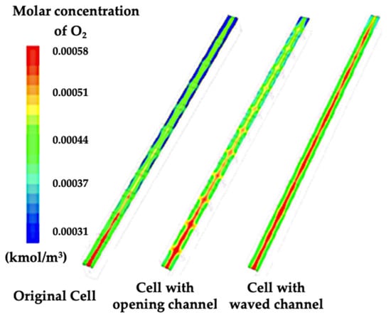
Figure 26.
The molar concentration of O2. Image reused and labels are enhanced from [76].
7. Fishbone Design
To enhance mass transfer and water removal below the ribs, Wang et al., 2021, [79] investigated a bio-inspired auxiliary fishbone-shaped flow-field (ASFF) pattern at the cathode parallel flow field (CPFF) in their study, which is illustrated in Figure 27. In comparison to parallel flow design, this offers definite advantages in terms of more efficiently supplying oxygen to the cathode GDL, resulting in a consistent electrochemical reaction in the cathode CL and better cell performance at high current densities. The same pumping loss observed in the parallel design is incurred at the expense of improvements in water removal. Water disposal and under-rib mass flow are further improved by expanding the number and width of sub-branch channels [79].
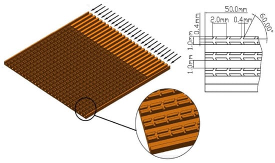
Figure 27.
Schematics of the CPFF pattern. Image is reused from [79].
8. Baffle Shape Design
In proton exchange membrane fuel cells with baffled flow channels, the shapes of the baffles influence reactant transfer and cell performance; the rectangular baffle is more advantageous for enhancing reactant transfer and cell performance. In contrast, the net power increase rate is higher when utilizing a rectangular baffled flow channel (20–21 percent) than when employing a straight flow channel. The shapes of the baffles affect how vortexes form in the flow channels and how much power is lost during the reactant delivery process. The pumping power increase is highest in rectangular baffled flow channels, and the vortexes formed in these channels are larger than in other shapes. The flow rates over different baffles are represented in Figure 28a–f.
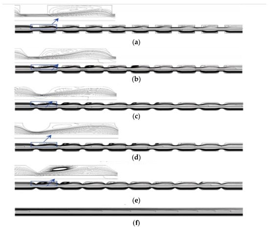
Figure 28.
(a) Rectangular baffles; (b) trapezoidal baffles; (c) waved baffles; (d) semicircular baffles; (e) triangular baffles; (f) straight flow channel. Image is reused from [80].
When the sloped leeward and streamlined windward sides are added around the rectangular baffles, the benefits of the rectangular baffled flow channel can be inherited. In the interim, vortexes and flow resistances can be decreased, which lowers the power losses accounted for by the pumping powers in the reactant-delivering process and increases the net powers. Moreover, extending the sloping leeward sides may reduce or eliminate the vortexes created in the flow channels, which would raise net powers and decrease the power loss accounted for by the pumping powers during reactant delivery [80]. Different cases of optimized flow channels to control the flow resistance are represented in Figure 29.

Figure 29.
Diagram of optimized baffled flow channels. Image is reused from [80].
9. Blockages
Heidary H., et al., 2016, [81] conducted a comparison between flow channels with and without obstructions. The performance of the cell increases by 26% when blockages are placed into the flow patterns of parallel flow fields. Channel blockage can help maintain liquid water within the channels at high flow rates and low relative humidity, which raises protonic conductivity and membrane hydration. The blockage of velocity is illustrated in the contour representation in Figure 30. The obstructions result in channel flooding, which lowers the permeability of oxygen to the porous zones. Due to greater water retention in the flow-field channels, the parallel serpentine with obstructions under low humid circumstances performed better.
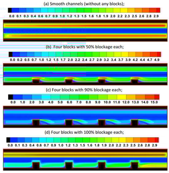
Figure 30.
Effect of different types of blockages on velocity contours in the middle plane of PEMFC. Image is reused from [81].
10. Manufacturing and Materials of Flow-Field Plates
Fuel cells using proton exchange membranes are a very promising substitute for traditional energy sources. Bipolar plates (BP) made of metal and graphite are essential parts of the fuel cell because they allow gases to circulate freely across the plate and conduct electrochemical processes. The expected properties of a bipolar plate are high mechanical strength, low corrosion, and excellent electrical conductivity. An equally important factor in the overall effectiveness of the cell is the flow pattern that is etched into it. Modern bipolar plates perform well, thanks to the development of novel plate designs that may meet some of the desired characteristics outlined by Mehta and Cooper [82] and Borup and Vanderburgh [17,83,84]. The various flow plate materials and manufacturing techniques are assessed in this review. In general, the three main methods of manufacturing processes are forming, subtractive manufacturing, and additive manufacturing. As categorized in Figure 31, each of these processes has pros and cons of its own, and Table 6 summarizes the comparison of different manufacturing techniques for various flow-field designs. For example, additive manufacturing is more easily manufactured, subtractive manufacturing is stronger, and forming operation production is faster. The material may be selected based on the cost, shape complexity, and process selection. Graphite, metallic, or polymer composite materials can all meet the necessary standards; however, each material has unique benefits and drawbacks. The two materials that are most frequently utilized to make bipolar plates are metal and carbon. The carbon bipolar plate resists corrosion and has a high electric conductivity, despite its fragility. Although the metal bipolar plate is highly electrically and mechanically conductible, it is not very resistant to corrosion [85].

Figure 31.
Bipolar Plate Manufacturing Processes.
Table 6.
Comparison of manufacturing processes for different flow designs.
Graphite plates are lightweight, chemically stable, and non-corrosive. Graphite plates are low in bulk resistivity and highly resistant to corrosion. It is commonly known that the interfacial ohmic losses between the bipolar plate and the MEA significantly reduce the PEMFC’s overall power output. These losses from graphite bipolar plate materials are very small in comparison to those from stainless steel. In contrast, the passive layer that forms on the surface of stainless steel greatly reduces electrical conductivity [47]. Materials made of graphite are better because they resist corrosion better. The conductivity of this substance is still much less than that of metallic materials [48]. Metal is a popular choice for a bipolar plate due to its strong electrical conductivity, excellent mechanical qualities, and low cost. Commonly used metals like stainless steel and aluminum may easily meet the bulk needs. They may be machined to create sheets that are roughly 0.05 inches thick when used as regular bipolar plates and 0.1 inches thick when used as coolant bipolar plates [49]. Metallic bipolar plates are a topic of ongoing investigation by several fuel-cell researchers. The materials related to potential metal bipolar plates include metals/alloys like SS 316L, high Si iron, Cr-Ni steel, nickel silver alloy, titanium, Ni steel, Monel alloy, and aluminum alloy. Intermetallic compounds like iron aluminides, titanium aluminides, nickel aluminides, and composites like Cu alloy with C fibers and Al composites can also be used. Typically, a coating is required to prevent corrosion on a metallic bipolar plate [52,86,87,88,89,90,91,92,93,94,95]. The two main processes used to make graphite plates are injection molding and compression molding [96]. Compressive molding relies on a straightforward production setup consisting of a press, a molding tool, and a bulk molding compound, among other process variables. De-mixing of bulk-molding compounds is a concern in the process, and significant flow lengths must be minimized. To ensure that all of the spaces are filled, more bulk molding materials need to be applied. The material is cured by the bulk molding compound through a chemically irreverent process. The surplus represents an intrinsic loss; raw material consumption and the quality-control (QC) pass rate must be balanced in the process.
The disadvantage is that the fiber and graphite content need to be smaller than in the bulk molding compounds used in compression molding. Although the graphite particles’ alignment is advantageous, this decreases through-plane conductivity, and fiber breakage decreases flexural strength. Alternative methods like additive manufacturing, also referred to as 3D printing, are a fascinating strategy for producing FFPs. It facilitates the easy production of small batches of plates with intricate flow-field channels without sacrificing design quality. As 3D printing involves layer incrementation, form-bound tools are not required. Its modest production rate and the associated costs are the only drawbacks.
The benefits of metals include their strong mechanical strength, low gas permeability, high electric and thermal conductivities, and ease of machining. They have, therefore, been thoroughly investigated as potential BP materials for PEMFC. Acidic environments are quite problematic for corrosion because they lead to the formation of metal ions, oxidants, and passive layers. One common technique for enhancing the metallic FFP’s resistance to corrosion is protective coating. Three types of coatings are widely used for aluminum BPs: metallic, carbon-based, and composites. Since noble metals like gold have a poor bond with the aluminum surface, they are utilized in pure metallic coatings. Stainless steel’s (SS) resistance to corrosion depends on the alloy; previous studies found that 316 SS and 316L SS were suitable for BPs. Low interfacial contact resistance SS BP life is increased by the insertion of a graphene-Ni layer. It was found that 316 SS has improved interfacial contact and corrosion resistance thanks to active screen plasma nitriding technology. Titanium nitride (TiN) can be coated via nitrogen plasma immersion ion implantation, plasma focus, pulsed bias arc ion plating, and magnetron sputtering (MS). It has strong chemical stability, low interfacial contact resistance, high corrosion resistance, and ease of fabrication. TiN-compatible titanium (Ti) substrates offer an alternative to the FFP material. Metallic plates are frequently made from sheets that can be stamped with any type of flow-field pattern. Nevertheless, FFPs are vulnerable to corrosion, which is accelerated by high temperatures, since they operate in harsh environments and are exposed to reactant gases. Therefore, other materials, including those carbon based, noble metals, carbides, and nitrides, either coat or do not coat the metallic plates [95,97,98,99,100].
This keeps the membrane from becoming poisoned and extends the life of the plates. Metals have excellent electrical and thermal conductivity, high strength, and quick production times. Research indicates that PEMFC is most suited for uncoated stainless steel with a greater Cr content, but gold-coated stainless steel more closely matches graphite in terms of conductivity, chemical resistance, lower thickness, and manufacturability. However, financial limitations prevent these from being sold commercially. Impacts of hydroforming, stamping, and forming techniques on metallic bipolar plates’ susceptibility to corrosion 304 stainless steel microchannel arrays were fabricated with an initial 51 m thickness and analyzed using potentiostatic and potentiodynamic techniques [101,102].
An initial flat blank was tested as a reference to mimic the PEMFC environment [30]. The working electrolyte was a 0.5 M H2SO4 solution, and the temperature was maintained at 80 °C. A hydroforming pressure range of 20–60 MPa, a stamping speed of 0.1–1 mm s1, and a stamping force of 100–300 kN were assessed. It was observed that, when the stamping force increased, the corrosion current increased as well. Pressure had a negligible effect. The hydroformed plate had a higher corrosion resistance than the blank plate (unless it was hydroformed at 60 MPa), but the stamped plate had a lower corrosion resistance (unless it was stamped at 300 kN). Additionally, it was shown that faster stamping rates enhanced the corrosion resistance of the plates [20,103,104].
To effectively utilize the qualities of each material, layers of graphite, stainless steel, and polymer are fused to create composite plates. Graphite increases electrical conductivity, polymer adds strength and reduces weight, and SS renders the stack chemically inert. To increase the transfer of charges, graphite powder combined with resin may be utilized. Polymers with excellent corrosion resistance can be 3D-printed to create intricate and endless flow channels. Composite plates are less expensive to produce than non-porous graphite and metal plates, but their performance is far lower.
Sun Lingjun, et al.’s, 2011, [105] study focused on the embossing procedure. Positioned between the aligned anode and cathode molds fitted on the bottom and top hot plates of HEX01 was an ABS (acrylonitrile butadiene styrene) plate. A rotary pump attached to the embossing chamber generated a vacuum lower than 0.1 bar to prevent air bubbles in the embossed polymer. At 140 degrees Celsius, which is 60° Celsius over the glass transition point, the ABS and the molds were heated. A 50 mm area was subjected to a 15 kN molding force for 300 s, or until the filling process was finished. The molding force persisted on the molds as they cooled. The sample was taken out and the molding force was released when the temperature fell to 85 degrees Celsius. The corrosive resistance of 316L SS plates covered with chromium carbide due to pinhole flaws was examined by Huang et al., 2016 [106]. The corrosion rate was found to increase initially before declining. It is determined that pin holes cause corrosion, the rate of which is regulated by ion migration under PEMFC simulation settings, leading to plate failure.
The review highlights different critical aspects of FF design in PEMFCs, covering bipolar plate configurations, such as pin-type, serpentine, and bio-inspired designs. The prominences of each design are explained with its design requirements and manufacturing challenges. Furthermore, advanced optimized FF designs, namely fishbone and baffle-shaped patterns exhibit high performance and efficiency. Further research is to be carried out on reducing the cost and improving the efficiency and durability. The summary and the future perspective of FF design needs are given in Table 7.
Table 7.
Comparison and future perspective in FF design of the PEMFC.
Author Contributions
Methodology, R.K.C. and S.R.D.; Software—Ansys 15.0, P.R.P.; Validation, D.T., T.S. and R.K.C.; Rough Draft P.R.P., S.R.D. and R.K.C.; Investigation, S.R.D., J.T. and R.K.C.; Resources, D.T. and T.S.; Data curation, P.R.P.; Writing—review and editing, R.K.C., J.T. and S.R.D.; Visualization, P.R.P.; Supervision, S.R.D. and J.T.; Project administration J.T. All authors have read and agreed to the published version of the manuscript.
Funding
This research received no external funding.
Data Availability Statement
It is a review article, and all data are adopted from the literature reported in the reference section. Images are redrawn as per journal requirements.
Acknowledgments
The corresponding author would like to acknowledge the Crackow University of Technology for contributing the article processing charges for this manuscript. The authors appreciate the editorial help performed by P. Ganguly, an Undergraduate intern at the VIT, Vellore in this manuscript.
Conflicts of Interest
The authors declare no conflicts of interest.
Abbreviations
| AFF | Advanced Flow Field |
| ASFF | Fishbone-Shaped Flow Field |
| BP | Bipolar Plates |
| CC | Current Conductive layer |
| CFD | Computational Fluid Dynamics |
| CFF | Convectional Flow Field |
| CL | Catalytic Layer |
| CPFF | Cathode Parallel Flow Field |
| DMFC | Direct Methanol Fuel Cell |
| EDM | Electronic Discharge Machine |
| EFC | Electrochemical Fuel Cell |
| FF | Fluid Field |
| FFP | Flow-Field Pattern |
| FEP | Fluorinated Ethylene Propylene |
| GDL | Digital Layer |
| GDM | Gas Diffusion Medium |
| LG | Serpentine design |
| L1 and L2 | Straight channel configuration |
| MEA | Membrane Exchange Assembly |
| MPSFF | Micro Porous Substrate Flow Field |
| NF | Net-flow Field |
| PEFC | Polymer Electrolyte Fuel Cells |
| PEMFC | Proton Exchange Membrane Fuel Cell |
| PSFP | Parallel Serpentine Flow Pattern |
| QC | Quality Control |
| S | Integrated flow field design |
| SF | Spares-flow Field |
| SFF | Serpentine Flow Field |
| SOFC | Solid Oxide Fuel Cell |
References
- Dhanushkodi, S.R.; Kundu, S.; Fowler, M.W.; Pritzker, M.D. Study of the effect of temperature on Pt dissolution in polymer electrolyte membrane fuel cells via accelerated stress tests. J. Power Sources 2014, 245, 1035–1045. [Google Scholar] [CrossRef]
- Li, X. Bipolar plates and flow field design. In Fuel Cells for Transportation; Woodhead Publishing: Cambridge, UK, 2023; pp. 305–337. [Google Scholar]
- Fuller, T.F.; Harb, J.N. Electrochemical Engineering; John Wiley & Sons: Hoboken, NJ, USA, 2018. [Google Scholar]
- Das, P.K.; Jiao, K.; Wang, Y.; Barbir, F.; Li, X. (Eds.) Fuel Cells for Transportation: Fundamental Principles and Applications; Elsevier: Amsterdam, The Netherlands, 2023. [Google Scholar]
- Das, P.K.; Barbir, F.; Jiao, K.; Wang, Y.; Li, X. Fuel cells for transportation—An overview. Fuel Cells Transp. 2023, 1–28. [Google Scholar]
- Talebi-Ghadikolaee, H.; Modanloo, V.; Elyasi, M.; Khatir, F.A. Multiple criteria decision support analysis for manu-facturing process parameters selection of metallic bipolar plates for polymer electrolyte membrane fuel cells. Proc. Inst. Mech. Eng. Part L J. Mater. Des. Appl. 2024, 238, 929–942. [Google Scholar]
- Zhang, J.; Zhang, H.; Wu, J.; Zhang, J. PEM Fuel Cell Fundamentals. In Pem Fuel Cell Testing and Diagnosis; Springer: Berlin/Heidelberg, Germany, 2013; pp. 1–42. [Google Scholar]
- Zhang, L.; Shi, Z. Optimization of serpentine flow field in proton-exchange membrane fuel cell under the effects of external factors. Alex. Eng. J. 2020, 60, 421–433. [Google Scholar] [CrossRef]
- Mayrhofer, K.J.; Arenz, M. Fuel cells: Log on for new catalysts. Nat. Chem. 2009, 1, 518. [Google Scholar] [CrossRef] [PubMed]
- Gröger, O.; Gasteiger, H.A.; Suchsland, J.-P. Electromobility: Batteries or fuel cells? J. Electrochem. Soc. 2015, 162, A2605–A2622. [Google Scholar] [CrossRef]
- Curnick, O.J.; Mendes, P.M.; Pollet, B.G. Enhanced durability of a Pt/C electrocatalyst derived from Nafion-stabilised colloidal platinum nanoparticles. Electrochem. Commun. 2010, 12, 1017–1020. [Google Scholar] [CrossRef]
- Dhanushkodi, S.R.; Tam, M.; Kundu, S.; Fowler, M.W.; Pritzker, M.D. Carbon corrosion fingerprint development and de-convolution of performance loss according to degradation mechanism in PEM fuel cells. J. Power Sources 2013, 240, 114–121. [Google Scholar] [CrossRef]
- Tongsh, C.; Wu, S.; Jiao, K.; Huo, W.; Du, Q.; Park, J.W.; Xuan, J.; Wang, H.; Brandon, N.P.; Guiver, M.D. Fuel cell stack redesign and component integration radically increase power density. Joule 2024, 8, 175–192. [Google Scholar] [CrossRef]
- Baratov, S.; Filonova, E.; Ivanova, A.; Hanif, M.B.; Irshad, M.; Khan, M.Z.; Motola, M.; Rauf, S.; Medvedev, D. Current and further tra-jectories in designing functional materials for solid oxide electrochemical cells: A review of other reviews. J. Energy Chem. 2024, 94, 302–331. [Google Scholar] [CrossRef]
- Guan, D.; Wang, B.; Zhang, J.; Shi, R.; Jiao, K.; Li, L.; Wang, Y.; Xie, B.; Zhang, Q.; Yu, J.; et al. Hydrogen society: From present to future. Energy Environ. Sci. 2023, 16, 4926–4943. [Google Scholar] [CrossRef]
- Li, X.; Sabir, I. Review of bipolar plates in PEM fuel cells: Flow-field designs. Int. J. Hydrogen Energy 2004, 30, 359–371. [Google Scholar] [CrossRef]
- Borup, R.L.; Vanderborgh, N.E. Design and testing criteria for bipolar plate materials for PEM fuel cell applications. MRS Online Proc. Libr. 1995, 393, 151–155. [Google Scholar] [CrossRef]
- Gößling, S.; Klages, M.; Haußmann, J.; Beckhaus, P.; Messerschmidt, M.; Arlt, T.; Kardjilov, N.; Manke, I.; Scholta, J.; Heinzel, A. Analysis of liquid water formation in polymer electrolyte membrane (PEM) fuel cell flow fields with a dry cathode supply. J. Power Sources 2016, 306, 658–665. [Google Scholar] [CrossRef]
- Pozio, A.; Zaza, F.; Masci, A.; Silva, R. Bipolar plate materials for PEMFCs: A conductivity and stability study. J. Power Sources 2008, 179, 631–639. [Google Scholar] [CrossRef]
- Chen, P.; Fang, F.; Zhang, Z.; Zhang, W.; Wang, Y. Self-assembled graphene film to enable highly conductive and corrosion resistant aluminum bipolar plates in fuel cells. Int. J. Hydrogen Energy 2017, 42, 12593–12600. [Google Scholar] [CrossRef]
- Wang, C. Low Cost PEM Fuel Cell Metal Bipolar Plates (No. DOE/EE/463); TreadStone Technologies, Inc.: Princeton, NJ, USA, 2013. [Google Scholar]
- Turhan, A.; Kim, S.; Hatzell, M.; Mench, M.M. Impact of channel wall hydrophobicity on through-plane water distribution and flooding behavior in a polymer electrolyte fuel cell. Electrochim. Acta 2010, 55, 2734–2745. [Google Scholar] [CrossRef]
- Papadias, D.D.; Ahluwalia, R.K.; Thomson, J.K.; Meyer, H.M., III; Brady, M.P.; Wang, H.; Turner, J.A.; Mukundan, R.; Borup, R. Degradation of SS316L bipolar plates in simulated fuel cell environment: Corrosion rate, barrier film formation kinetics and contact resistance. J. Power Sources 2015, 273, 1237–1249. [Google Scholar] [CrossRef]
- Reiser, C.A.; Sawyer, R.D. Solid Polymer Electrolyte Fuel Cell Stack Water Management System; International Fuel Cells Corp.: South Windsor, CT, USA, 1988. [Google Scholar]
- Water and Heat Management in Solid Polymer Fuel Cell Stack. U.S. Patent 4826742, 2 May 1989. Available online: https://patents.google.com/patent/US4826742 (accessed on 25 June 2021).
- Guo, N.; Leu, M.C.; Koylu, U.O. Network based optimization model for pin-type flow field of polymer electrolyte membrane fuel cell. Int. J. Hydrogen Energy 2013, 38, 6750–6761. [Google Scholar] [CrossRef]
- Dong-Hui, W.; Lin-Zhi, Y.; Zhong-Yu, P.; Cong-Da, L.; Gang, L.; Qiao-Hui, L. A novel intersectant flow field of metal bipolar plate for proton exchange membrane fuel cell. Int. J. Energy Res. 2017, 41, 2184–2193. [Google Scholar] [CrossRef]
- Bhattacharya, D.; Mukhopadhyay, J.; Biswas, N.; Basu, R.N.; Das, P.K. Performance evaluation of different bipolar plate designs of 3D planar anode-supported SOFCs. Int. J. Heat Mass Transf. 2018, 123, 382–396. [Google Scholar] [CrossRef]
- Zhang, G.; Guan, Z.; Li, D.; Li, G.; Bai, S.; Sun, K.; Cheng, H. Optimization Design of a Parallel Flow Field for PEMFC with Bosses in Flow Channels. Energies 2023, 16, 5492. [Google Scholar] [CrossRef]
- Lim, B.; Majlan, E.; Daud, W.; Rosli, M.; Husaini, T. Numerical analysis of modified parallel flow field designs for fuel cells. Int. J. Hydrogen Energy 2017, 42, 9210–9218. [Google Scholar] [CrossRef]
- Li, X.; Sabir, I.; Park, J. A flow channel design procedure for PEM fuel cells with effective water removal. J. Power Sources 2007, 163, 933–942. [Google Scholar] [CrossRef]
- Spaziante, P.; Pellegri, A. Bipolar Separator for Electrochemical Cells and Method of Preparation Thereof. 1981. Available online: https://patents.google.com/patent/CA1103206A/en-20US4325121.pdf (accessed on 25 June 2021).
- Hossain, M.S.; Shabani, B.; Cheung, C.P. Enhanced gas flow uniformity across parallel channel cathode flow field of Proton Exchange Membrane fuel cells. Int. J. Hydrogen Energy 2017, 42, 5272–5283. [Google Scholar] [CrossRef]
- Chiu, H.-C.; Jang, J.-H.; Yan, W.-M.; Li, H.-Y.; Liao, C.-C. A three-dimensional modeling of transport phenomena of proton exchange membrane fuel cells with various flow fields. Appl. Energy 2012, 96, 359–370. [Google Scholar] [CrossRef]
- Sauermoser, M.; Kizilova, N.; Pollet, B.G.; Kjelstrup, S. Flow Field Patterns for Proton Exchange Membrane Fuel Cells. In Frontiers in Energy Research; Frontiers Media SA: Lausanne, Switzerland, 2020; Volume 8. [Google Scholar] [CrossRef]
- Li, H.; Tang, Y.; Wang, Z.; Shi, Z.; Wu, S.; Song, D.; Zhang, J.; Fatih, K.; Zhang, J.; Wang, H.; et al. A review of water flooding issues in the proton exchange membrane fuel cell. J. Power Sources 2007, 178, 103–117. [Google Scholar] [CrossRef]
- Limjeerajarus, N.; Charoen-Amornkitt, P. Effect of different flow field designs and number of channels on performance of a small PEFC. Int. J. Hydrogen Energy 2015, 40, 7144–7158. [Google Scholar] [CrossRef]
- Cullen, D.A.; Neyerlin, K.C.; Ahluwalia, R.K.; Mukundan, R.; More, K.L.; Borup, R.L.; Weber, A.Z.; Myers, D.J.; Kusoglu, A. New roads and challenges for fuel cells in heavy-duty transportation. Nat. Energy 2021, 6, 462–474. [Google Scholar] [CrossRef]
- Wang, Y.; Wang, S.; Liu, S.; Li, H.; Zhu, K. Optimization of reactants relative humidity for high performance of polymer electrolyte membrane fuel cells with co-flow and counter-flow configuration. Energy Convers. Manag. 2020, 205, 112369. [Google Scholar] [CrossRef]
- Nam, J.H.; Lee, K.-J.; Sohn, S.; Kim, C.-J. Multi-pass serpentine flow-fields to enhance under-rib convection in polymer electrolyte membrane fuel cells: Design and geometrical characterization. J. Power Sources 2009, 188, 14–23. [Google Scholar] [CrossRef]
- Saco, S.A.; Raj, R.T.K.; Karthikeyan, P. A study on scaled up proton exchange membrane fuel cell with various flow channels for optimizing power output by effective water management using numerical technique. Energy 2016, 113, 558–573. [Google Scholar] [CrossRef]
- Chilver-Stainer, J.; Elbarghthi, A.F.A.; Wen, C.; Tian, M. Power output optimisation via arranging gas flow channels for low-temperature polymer electrolyte membrane fuel cell (PEMFC) for hydrogen-powered vehicles. Energies 2023, 16, 3722. [Google Scholar] [CrossRef]
- Jin, C.K.; Kang, C.G. Fabrication process analysis and experimental verification for aluminum bipolar plates in fuel cells by vacuum die-casting. J. Power Sources 2011, 196, 8241–8249. [Google Scholar] [CrossRef]
- Wang, Y.; Liao, X.; Liu, G.; Xu, H.; Guan, C.; Wang, H.; Li, H.; He, W.; Qin, Y. Review of flow field designs for polymer electrolyte membrane fuel cells. Energies 2023, 16, 4207. [Google Scholar] [CrossRef]
- Kim, A.-R.; Shin, S.; Um, S. Multidisciplinary approaches to metallic bipolar plate design with bypass flow fields through deformable gas diffusion media of polymer electrolyte fuel cells. Energy 2016, 106, 378–389. [Google Scholar] [CrossRef]
- Rahimi-Esbo, M.; Rahgoshay, S.; Hassani, M.; Firouzjaei, K.D. Novel design and numerical evaluating of a cooling flow field in PEMFC with metallic bipolar plates. Int. J. Hydrogen Energy 2020, in press. [Google Scholar] [CrossRef]
- Iranzo, A.; Gregorio, J.M.; Boillat, P.; Rosa, F. Bipolar plate research using Computational Fluid Dynamics and neutron radiography for proton exchange membrane fuel cells. Int. J. Hydrogen Energy 2020, 45, 12432–12442. [Google Scholar] [CrossRef]
- Ouellette, D.; Ozden, A.; Ercelik, M.; Colpan, C.O.; Ganjehsarabi, H.; Li, X.; Hamdullahpur, F. Assessment of different bio-inspired flow fields for direct methanol fuel cells through 3D modeling and experimental studies. Int. J. Hydrogen Energy 2018, 43, 1152–1170. [Google Scholar] [CrossRef]
- Ozden, A.; Ercelik, M.; Ouellette, D.; Colpan, C.O.; Ganjehsarabi, H.; Hamdullahpur, F. Designing, modeling and performance investigation of bio-inspired flow field based DMFCs. Int. J. Hydrogen Energy 2017, 42, 21546–21558. [Google Scholar] [CrossRef]
- Aiyejina, A.; Sastry, M.K.S. PEMFC flow channel geometry optimization: A review. J. Fuel Cell Sci. Technol. 2011, 9, 011011. [Google Scholar] [CrossRef]
- Ghadhban, S.A.; Alawee, W.H.; Dhahad, H.A. Study effects of bio-inspired flow filed design on Polymer Electrolyte Membrane fuel cell performance. Case Stud. Therm. Eng. 2021, 24, 100841. [Google Scholar] [CrossRef]
- Li, Z.; Feng, K.; Wang, Z.; Cai, X.; Yao, C.; Wu, Y. Investigation of single-layer and multilayer coatings for aluminum bipolar plate in polymer electrolyte membrane fuel cell. Int. J. Hydrogen Energy 2014, 39, 8421–8430. [Google Scholar] [CrossRef]
- Roshandel, R.; Arbabi, F.; Moghaddam, G.K. Simulation of an innovative flow-field design based on a bio inspired pattern for PEM fuel cells. Renew. Energy 2011, 41, 86–95. [Google Scholar] [CrossRef]
- San, F.G.B.; Tekin, G. A review of thermoplastic composites for bipolar plate applications. Int. J. Energy Res. 2013, 37, 283–309. [Google Scholar] [CrossRef]
- Palumbo, G.; Piccininni, A. Numerical–experimental investigations on the manufacturing of an aluminium bipolar plate for proton exchange membrane fuel cells by warm hydroforming. Int. J. Adv. Manuf. Technol. 2013, 69, 731–742. [Google Scholar] [CrossRef]
- Asadzade, M.; Shamloo, A. Design and simulation of a novel bipolar plate based on lung-shaped bio-inspired flow pattern for PEM fuel cell. Int. J. Energy Res. 2017, 41, 1730–1739. [Google Scholar] [CrossRef]
- James, B.D.; Huya-Kouadio, J.M.; Houchins, C.; DeSantis, D.A. Mass Production Cost Estimation of Direct H2 PEM Fuel Cell Systems for Transportation Applications: 2018 Update. 2018. Available online: https://www.energy.gov/sites/prod/files/2019/12/f70/fcto-sa-2018-transportation-fuel-cell-cost-analysis.pdf (accessed on 5 April 2021).
- Boddu, R.; Marupakula, U.K.; Summers, B.; Majumdar, P. Development of bipolar plates with different flow channel configurations for fuel cells. J. Power Sources 2009, 189, 1083–1092. [Google Scholar] [CrossRef]
- Kang, H.C.; Jum, K.M.; Sohn, Y.J. Performance of unit PEM fuel cells with a leaf-vein-simulating flow field-patterned bipolar plate. Int. J. Hydrogen Energy 2019, 44, 24036–24042. [Google Scholar] [CrossRef]
- Kloess, J.P.; Wang, X.; Liu, J.; Shi, Z.; Guessous, L. Investigation of bio-inspired flow channel designs for bipolar plates in proton exchange membrane fuel cells. J. Power Sources 2008, 188, 132–140. [Google Scholar] [CrossRef]
- Trogadas, P.; Cho, J.I.S.; Neville, T.P.; Marquis, J.; Wu, B.; Brett, D.J.L.; Coppens, M.-O. A lung-inspired approach to scalable and robust fuel cell design. Energy Environ. Sci. 2017, 11, 136–143. [Google Scholar] [CrossRef]
- Khan, M.J.; Iqbal, M.T. Dynamic modeling, and simulation of a small wind-fuel cell hybrid energy system. Renew Energy 2005, 30, 421–439. [Google Scholar] [CrossRef]
- Perez-Raya, I.; Hernandez-Guerrero, A.; Elizalde-Blancas, F.; Juarez-Robles, D.; Almanza-Huerta, L. 3D analysis of a new radial channel for pemfcs and comparison with a traditional channeled system. In Proceedings of the ASME 2010 International Mechanical Engineering Congress and Exposition, Vancouver, BC, Canada, 12–18 November 2010; pp. 899–908. [Google Scholar]
- Cano-Andrade, S.; Hernandez-Guerrero, A.; von Spakovsky, M.; Damian-Ascencio, C.; Rubio-Arana, J. Current density and polarization curves for radial flow field patterns applied to PEMFCs (Proton Exchange Membrane Fuel Cells). Energy 2010, 35, 920–927. [Google Scholar] [CrossRef]
- Friess, B.; Hoorfar, M. Development of a novel radial cathode flow field for PEMFC. Int. J. Hydrogen Energy 2012, 37, 7719–7729. [Google Scholar] [CrossRef]
- Juarez-Robles, D.; Herna´ndez-Guerrero, A.; Damia´n-Ascencio, C.E.; Rubio-Arana, C. Three dimensional analysis of a PEM fuel cell with the shape of a fermat spiral for the flow channel configuration. In Proceedings of the ASME 2008 International Mechanical Engineering Congress and Exposition, Boston, MA, USA, 31 October–6 November 2008; pp. 711–720. [Google Scholar]
- Mench, M.M. Fuel Cell Engines; 2008; pp. 1–515. Available online: https://onlinelibrary.wiley.com/doi/book/10.1002/9780470209769 (accessed on 5 April 2021).
- Ahmed, D.H.; Sung, H.J. Effects of channel geometrical configuration and shoulder width on PEMFC performance at high current density. J. Power Sources 2006, 162, 327–339. [Google Scholar] [CrossRef]
- Kahraman, H.; Orhan, M.F. Flow field bipolar plates in a proton exchange membrane fuel cell: Analysis & modeling. Energy Convers. Manag. 2017, 133, 363–384. [Google Scholar] [CrossRef]
- Owejan, J.P.; Trabold, T.A.; Jacobson, D.L.; Arif, M.; Kandlikar, S.G. Effects of flow field and diffusion layer properties on water ac-cumulation in a PEM fuel cell. Int. J. Hydrogen Energy 2007, 32, 4489–4502. [Google Scholar] [CrossRef]
- Kahraman, H.; Haşimoğlu, C.; Çevik, İ.; Murcak, A. A different flow field design approach for performance improvement of a PEMFC. Acta Phys. Pol. A 2017, 131, 484–486. [Google Scholar] [CrossRef]
- Wang, C.; Zhang, Q.; Lu, J.; Shen, S.; Yan, X.; Zhu, F.; Cheng, X.; Zhang, J. Effect of height/width-tapered flow fields on the cell performance of polymer electrolyte membrane fuel cells. Int. J. Hydrogen Energy 2017, 42, 23107–23117. [Google Scholar] [CrossRef]
- Tiss, F.; Chouikh, R.; Guizani, A. A numerical investigation of the effects of membrane swelling in polymer electrolyte fuel cells. Energy Convers. Manag. 2013, 67, 318–324. [Google Scholar] [CrossRef]
- Al-Baghdadi, M.A.R.S.; Al-Janabi, H.A.K.S. Modeling optimizes PEM fuel cell performance using three-dimensional multi-phase computational fluid dynamics model. Energy Convers. Manag. 2007, 48, 3102–3119. [Google Scholar] [CrossRef]
- Shimpalee, S.; Van Zee, J.W. Numerical studies on rib & channel dimension of flow-field on PEMFC performance. Int. J. Hydrog. Energy 2007, 32, 842–856. [Google Scholar]
- Qiu, D.; Peng, L.; Tang, J.; Lai, X. Numerical analysis of air-cooled proton exchange membrane fuel cells with various cathode flow channels. Energy 2020, 198, 117334. [Google Scholar] [CrossRef]
- Chowdhury, M.Z.; Genc, O.; Toros, S. Numerical optimization of channel to land width ratio for PEM fuel cell. Int. J. Hydrogen Energy 2018, 43, 10798–10809. [Google Scholar] [CrossRef]
- Wang, X.-D.; Duan, Y.-Y.; Yan, W.-M.; Lee, D.-J.; Su, A.; Chi, P.-H. Channel aspect ratio effect for serpentine proton exchange membrane fuel cell: Role of sub-rib convection. J. Power Sources 2009, 193, 684–690. [Google Scholar] [CrossRef]
- Wang, Y.; Si, C.; Qin, Y.; Wang, X.; Fan, Y.; Gao, Y. Bio-inspired design of an auxiliary fishbone-shaped cathode flow field pattern for polymer electrolyte membrane fuel cells. Energy Convers. Manag. 2020, 227, 113588. [Google Scholar] [CrossRef]
- Guo, H.; Chen, H.; Ye, F.; Ma, C.F. Baffle shape effects on mass transfer and power loss of proton exchange membrane fuel cells with different baffled flow channels. Int. J. Energy Res. 2019, 43, 2737–2755. [Google Scholar] [CrossRef]
- Heidary, H.; Kermani, M.J.; Dabir, B. Influences of bipolar plate channel blockages on PEM fuel cell performances. Energy Convers. Manag. 2016, 124, 51–60. [Google Scholar] [CrossRef]
- Mehta, V.; Cooper, J.S. Review and analysis of PEM fuel cell design and manufacturing. J. Power Sources 2003, 114, 32–53. [Google Scholar] [CrossRef]
- Cooper, J.S. Design analysis of PEMFC bipolar plates considering stack manufacturing and environment impact. J. Power Sources 2004, 129, 152–169. [Google Scholar] [CrossRef]
- Yeetsorn, R.; Maiket, Y. Metal-insert technique for polypropylene composite bipolar plate manufacturing. J. Polym. Eng. 2020, 41, 72–82. [Google Scholar] [CrossRef]
- Kim, K.H.; Lim, J.W.; Kim, M.; Gil Lee, D. Development of carbon fabric/graphite hybrid bipolar plate for PEMFC. Compos. Struct. 2013, 98, 103–110. [Google Scholar] [CrossRef]
- Pu, N.-W.; Shi, G.-N.; Liu, Y.-M.; Sun, X.; Chang, J.-K.; Sun, C.-L.; Ger, M.-D.; Chen, C.-Y.; Wang, P.-C.; Peng, Y.-Y.; et al. Graphene was grown on stainless steel as a high-performance and eco-friendly anti-corrosion coating for polymer electrolyte membrane fuel cell bipolar plates. J. Power Sources 2015, 282, 248–256. [Google Scholar] [CrossRef]
- Lin, K.; Li, X.; Sun, Y.; Luo, X.; Dong, H. Active screen plasma nitriding of 316 stainless steel for the application of bipolar plates in proton exchange membrane fuel cells. Int. J. Hydrogen Energy 2014, 39, 21470–21479. [Google Scholar] [CrossRef]
- Zhao, Y.; Wei, L.; Yi, P.; Peng, L. Influence of Cr-C film composition on electrical and corrosion properties of 316L stainless steel as bipolar plates for PEMFCs. Int. J. Hydrogen Energy 2016, 41, 1142–1150. [Google Scholar] [CrossRef]
- Omrani, M.; Habibi, M.; Amrollahi, R.; Khosravi, A. Improvement of corrosion and electrical conductivity of 316L stainless steel as bipolar plate by TiN nanoparticle implantation using plasma focus. Int. J. Hydrogen Energy 2012, 37, 14676–14686. [Google Scholar] [CrossRef]
- Lee, S.; Kakati, N.; Maiti, J.; Jee, S.; Kalita, D.; Yoon, Y. Corrosion and electrical properties of CrN- and TiN-coated 316L stainless steel used as bipolar plates for polymer electrolyte membrane fuel cells. Thin Solid Films 2012, 529, 374–379. [Google Scholar] [CrossRef]
- Antunes, R.A.; Oliveira, M.C.L.; Ett, G.; Ett, V. Corrosion of metal bipolar plates for PEM fuel cells: A review. Int. J. Hydrogen Energy 2010, 35, 3632–3647. [Google Scholar] [CrossRef]
- Yang, G.; Yu, S.; Mo, J.; Kang, Z.; Dohrmann, Y.; List, F.A.; Green, J.B.; Babu, S.S.; Zhang, F.-Y. Bipolar plate development with additive manufacturing and protective coating for durable and high-efficiency hydrogen production. J. Power Sources 2018, 396, 590–598. [Google Scholar] [CrossRef]
- Elyasi, M.; Khatir, F.A.; Hosseinzadeh, M. Manufacturing metallic bipolar plate fuel cells through rubber pad forming process. Int. J. Adv. Manuf. Technol. 2016, 89, 3257–3269. [Google Scholar] [CrossRef]
- Sisan, M.M.; Sereshki, M.A.; Khorsand, H.; Siadati, M. Carbon coating for corrosion protection of SS-316L and AA-6061 as bipolar plates of PEM fuel cells. J. Alloy. Compd. 2014, 613, 288–291. [Google Scholar] [CrossRef]
- Porstmann, S.; Wannemacher, T.; Drossel, W.-G. A comprehensive comparison of state-of-the-art manufacturing methods for fuel cell bipolar plates including anticipated future industry trends. J. Manuf. Process. 2020, 60, 366–383. [Google Scholar] [CrossRef]
- Hermann, A.; Chaudhuri, T.; Spagnol, P. Bipolar plates for PEM fuel cells: A review. Int. J. Hydrogen Energy 2005, 30, 1297–1302. [Google Scholar] [CrossRef]
- Gladczuk, L.; Joshi, C.; Patel, A.; Guiheen, J.; Iqbal, Z.; Sosnowski, M. Corrosion-Resistant Tantalum Coatings for PEM Fuel Cell Bipolar Plates. MRS Proc. 2002, 756, 72. [Google Scholar] [CrossRef]
- Asri, N.F.; Husaini, T.; Sulong, A.B.; Majlan, E.H.; Daud, W.R.W. Coating of stainless steel and titanium bipolar plates for anticorrosion in PEMFC: A review. Int. J. Hydrogen Energy 2017, 42, 9135–9148. [Google Scholar] [CrossRef]
- Stoot, A.C.; Camilli, L.; Spiegelhauer, S.-A.; Yu, F.; Bøggild, P. Multilayer graphene for long-term corrosion protection of stainless steel bipolar plates for polymer electrolyte membrane fuel cell. J. Power Sources 2015, 293, 846–851. [Google Scholar] [CrossRef]
- Barranco, J.; Barreras, F.; Lozano, A.; Lopez, A.M.; Roda, V.; Martin, J.; Maza, M.; Fuentes, G.G.; Almandoz, E. Cr and Zr/Cr nitride CAE-PVD coated aluminum bipolar plates for polymer electrolyte membrane fuel cells. Int. J. Hydrogen Energy 2010, 35, 11489–11498. [Google Scholar] [CrossRef]
- Steele, B.C.H.; Heinzel, A. Materials for fuel cell technologies. In Materials for Sustainable Energy; Nature Publishing Group: London, UK, 2011; pp. 224–231. [Google Scholar]
- Daehn, G.S.; Hatkevich, S.; Shang, J.; Wilkerson, L. Commercialization of fuel cell bipolar plate manufacturing by electromagnetic forming. In Proceedings of the 4th International Conference on High Speed Forming, Columbus, OH, USA, 9–10 March 2010. [Google Scholar]
- Heras, N.d.L.; Roberts, E.P.L.; Langton, R.; Hodgson, D.R. A review of metal separator plate materials suitable for automotive PEMfuel cells. Energy Environ. Sci. 2008, 2, 206–214. [Google Scholar] [CrossRef]
- Deyab, M. Corrosion protection of aluminum bipolar plates with polyaniline coating containing carbon nanotubes in acidic medium inside the polymer electrolyte membrane fuel cell. J. Power Sources 2014, 268, 50–55. [Google Scholar] [CrossRef]
- Sun, L.; Liu, C.; Liang, J.; Zhu, X.; Cui, T. A self-pumping and self-breathing micro direct methanol fuel cell with polymer bipolar plates. J. Power Sources 2011, 196, 7533–7540. [Google Scholar] [CrossRef]
- Huang, N.; Yu, H.; Xu, L.; Zhan, S.; Sun, M.; Kirk, D.W. Corrosion kinetics of 316L stainless steel bipolar plate with chromiumcarbide coating in simulated PEMFC cathodic environment. Results Phys. 2016, 6, 730–736. [Google Scholar] [CrossRef]

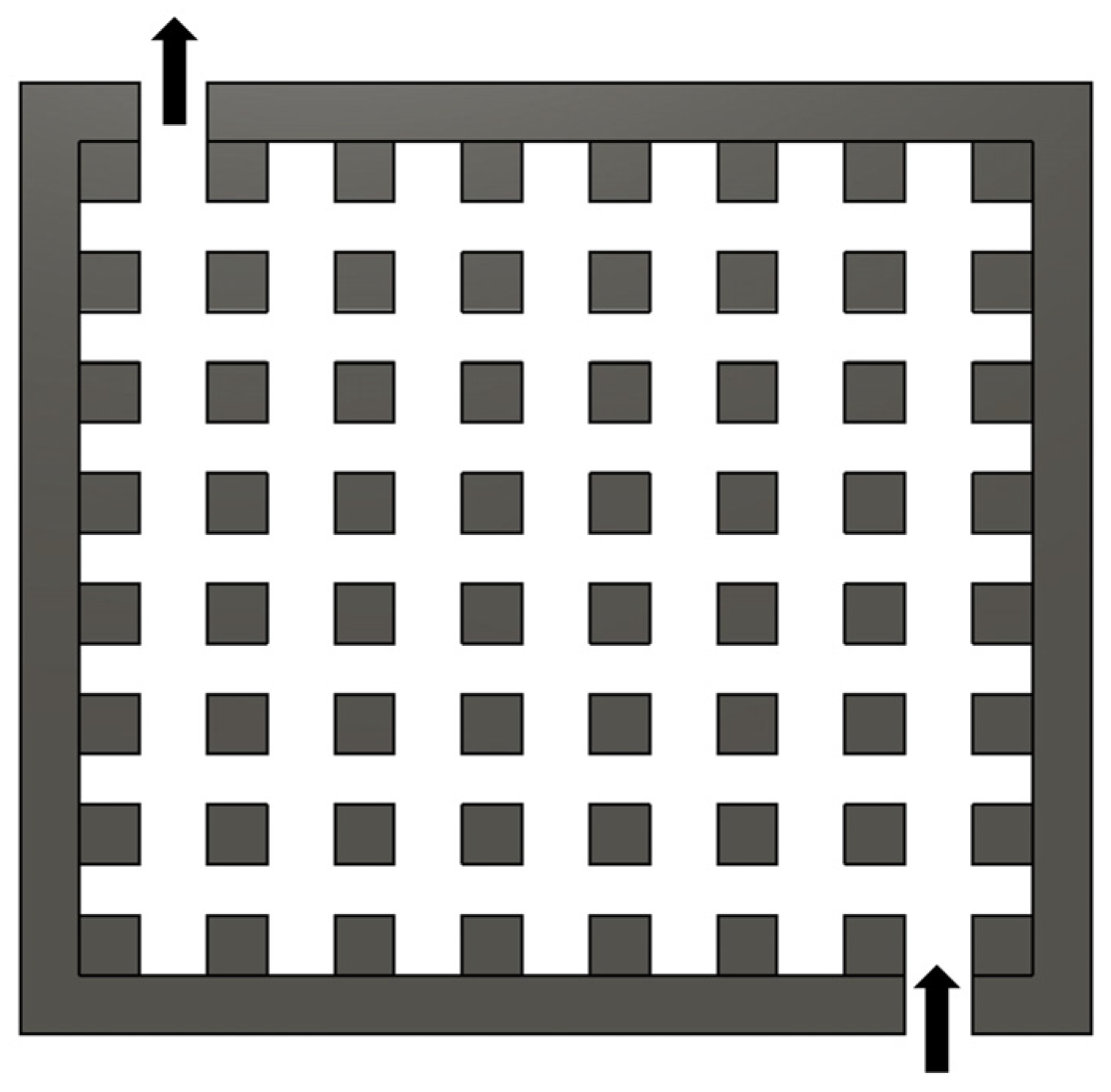
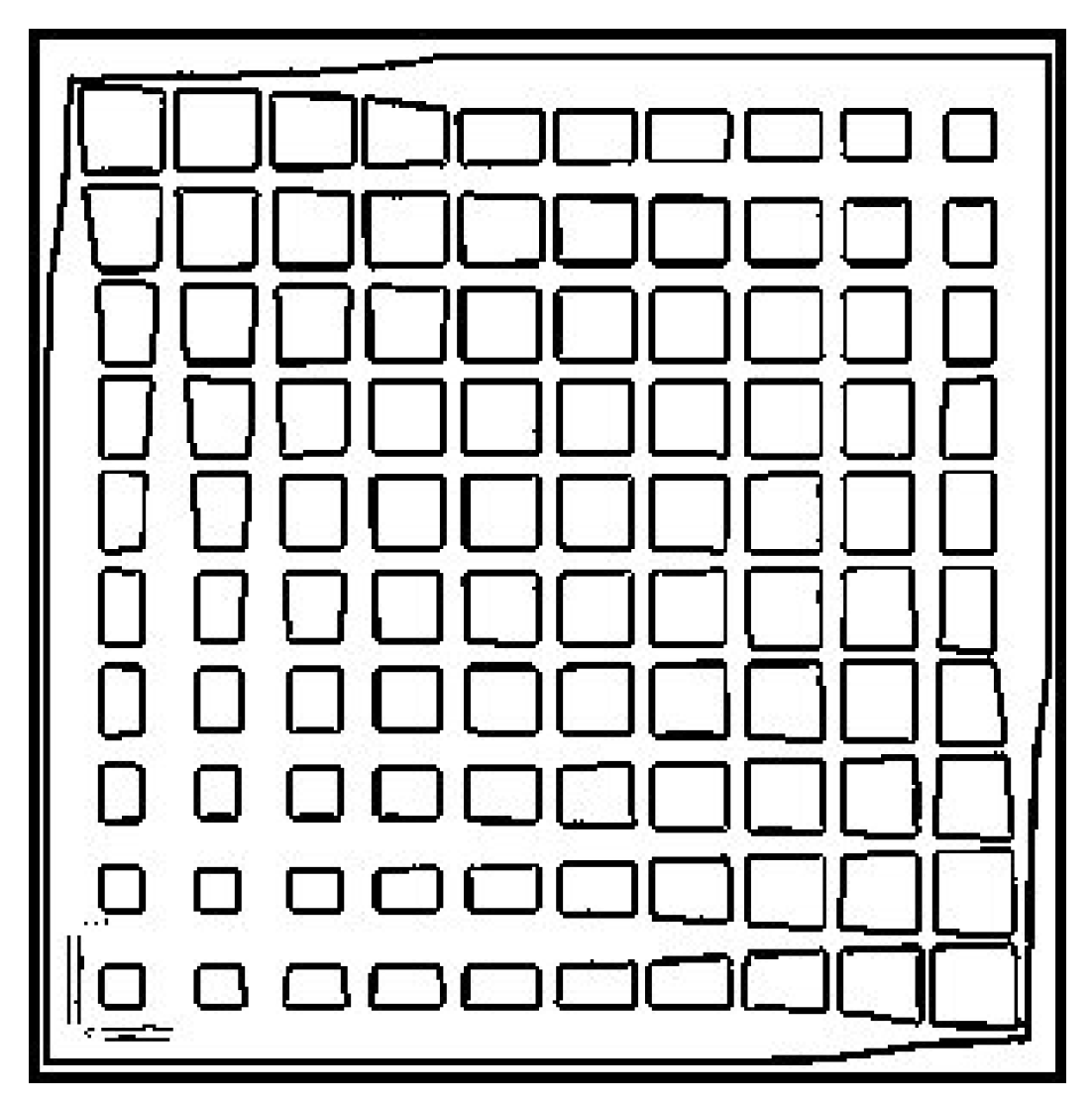
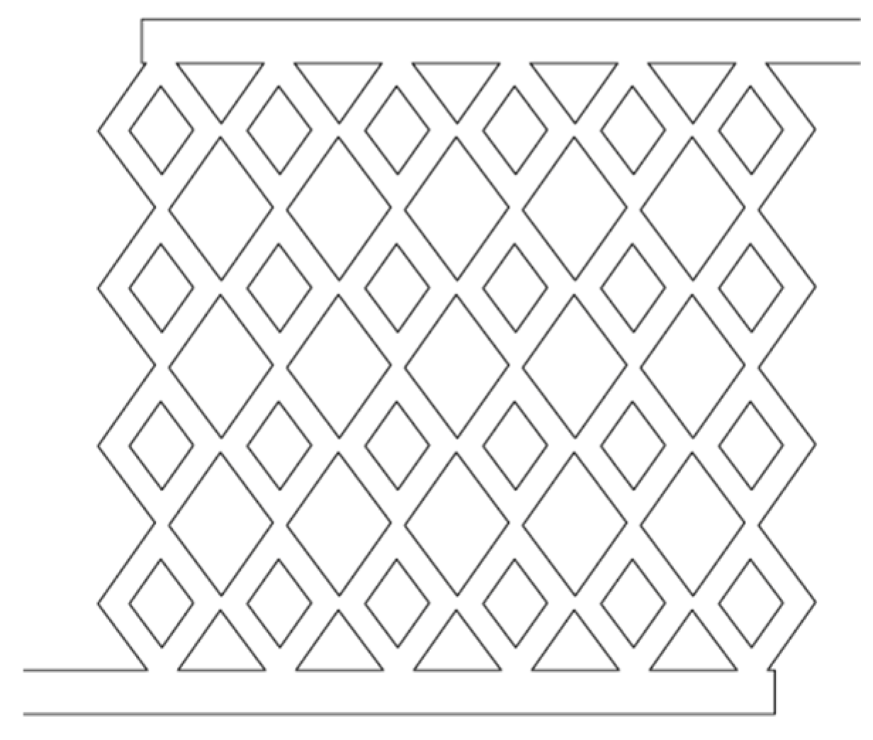
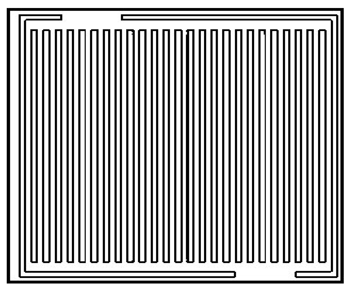
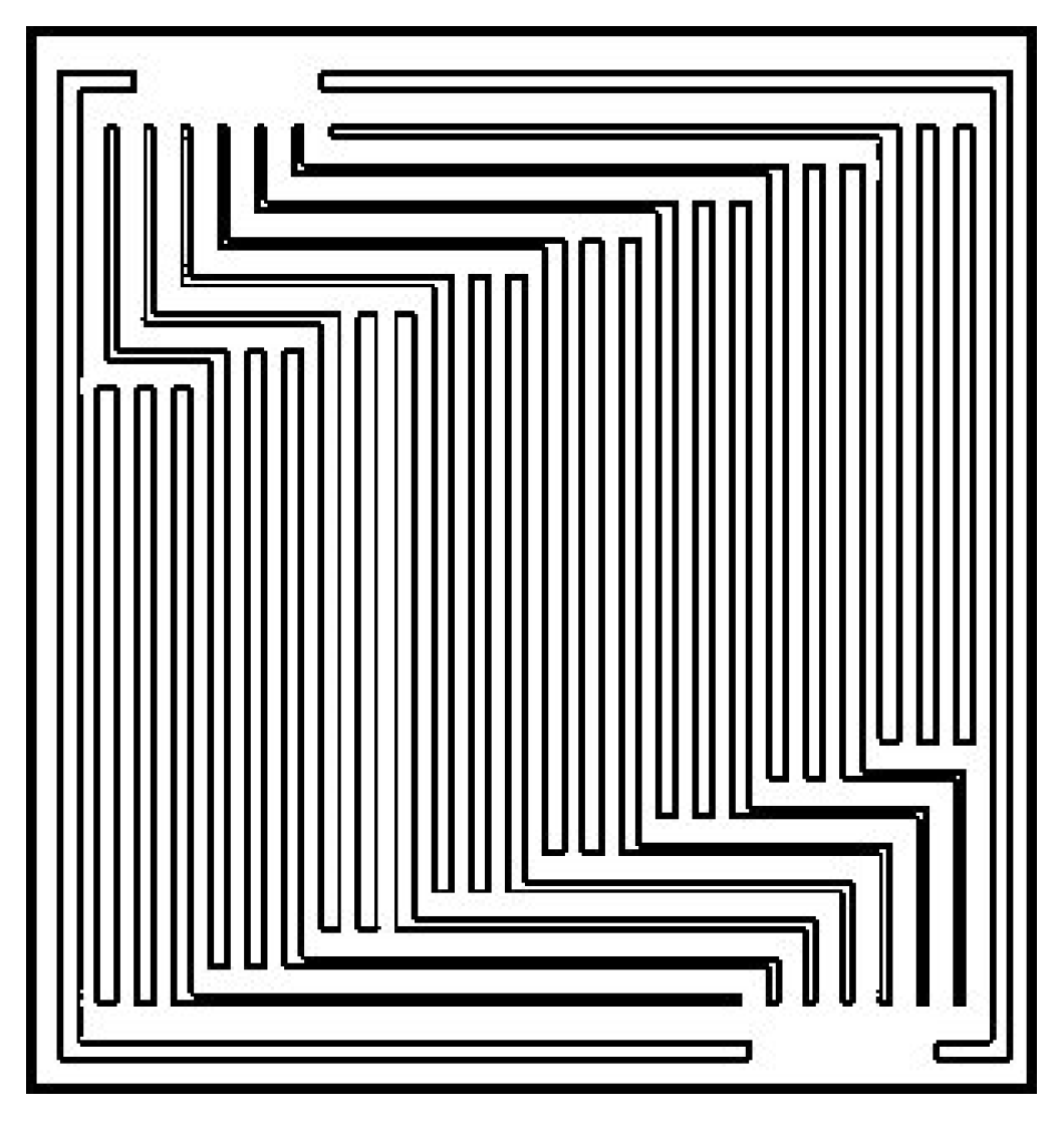
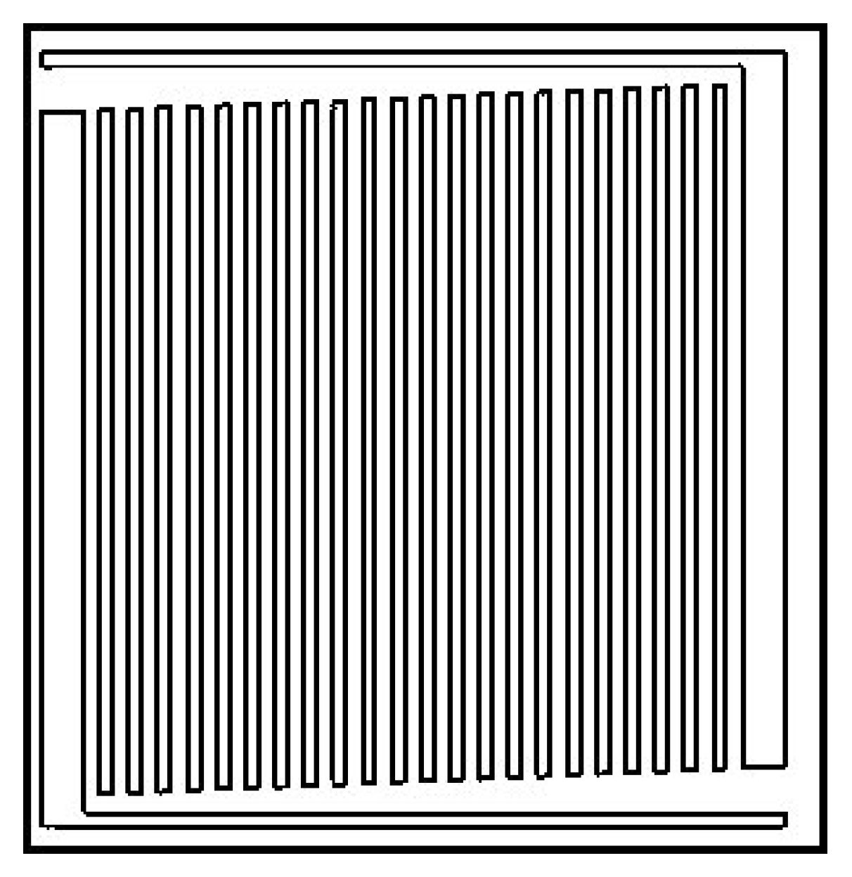
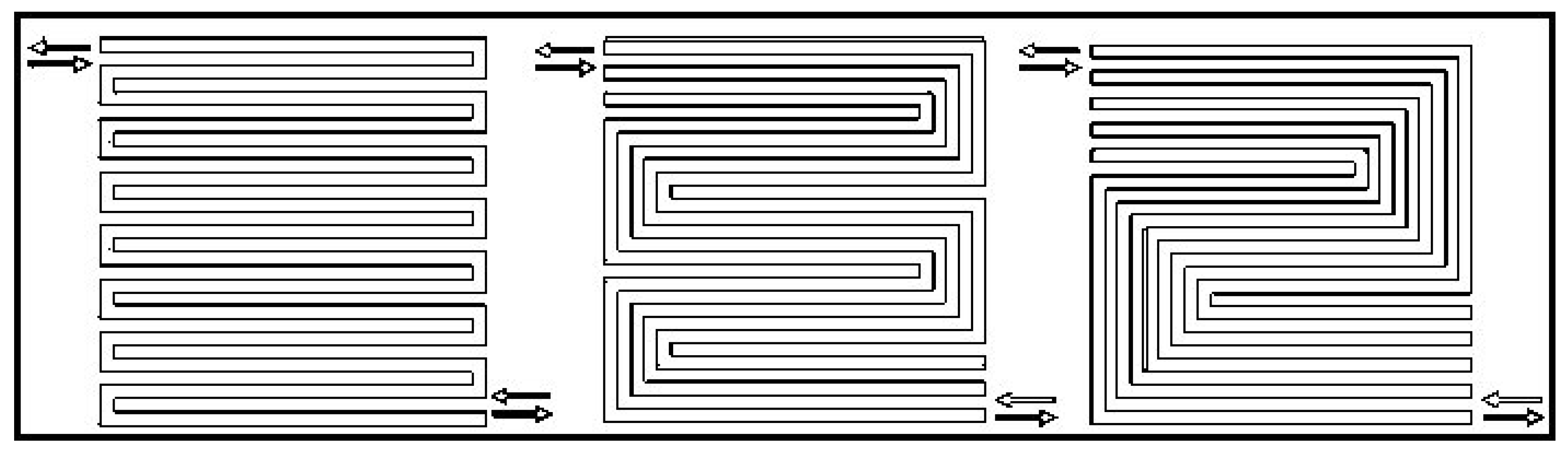
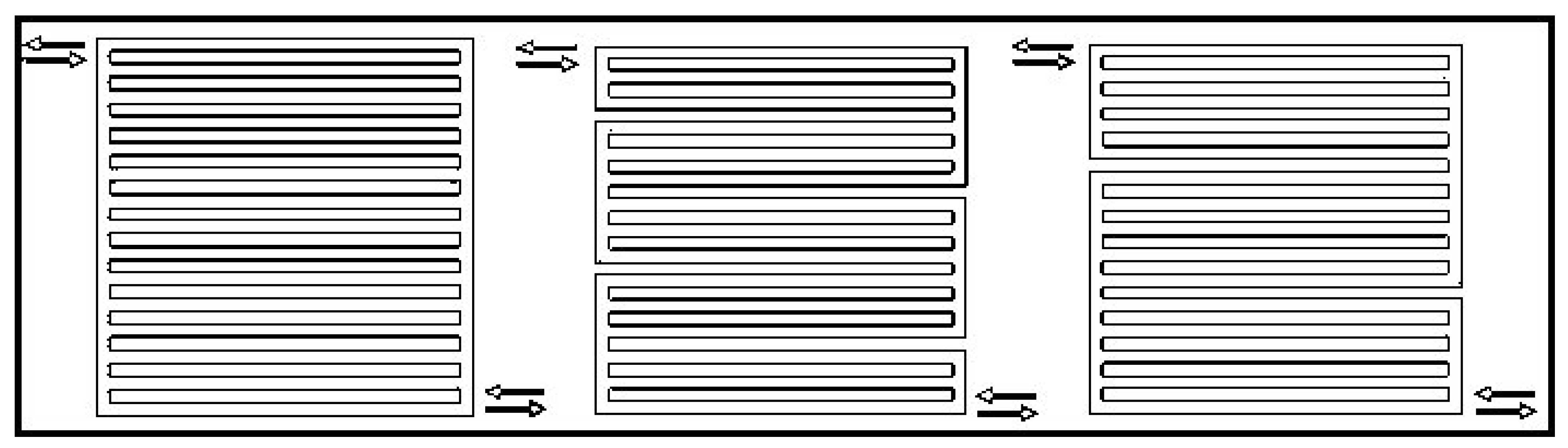


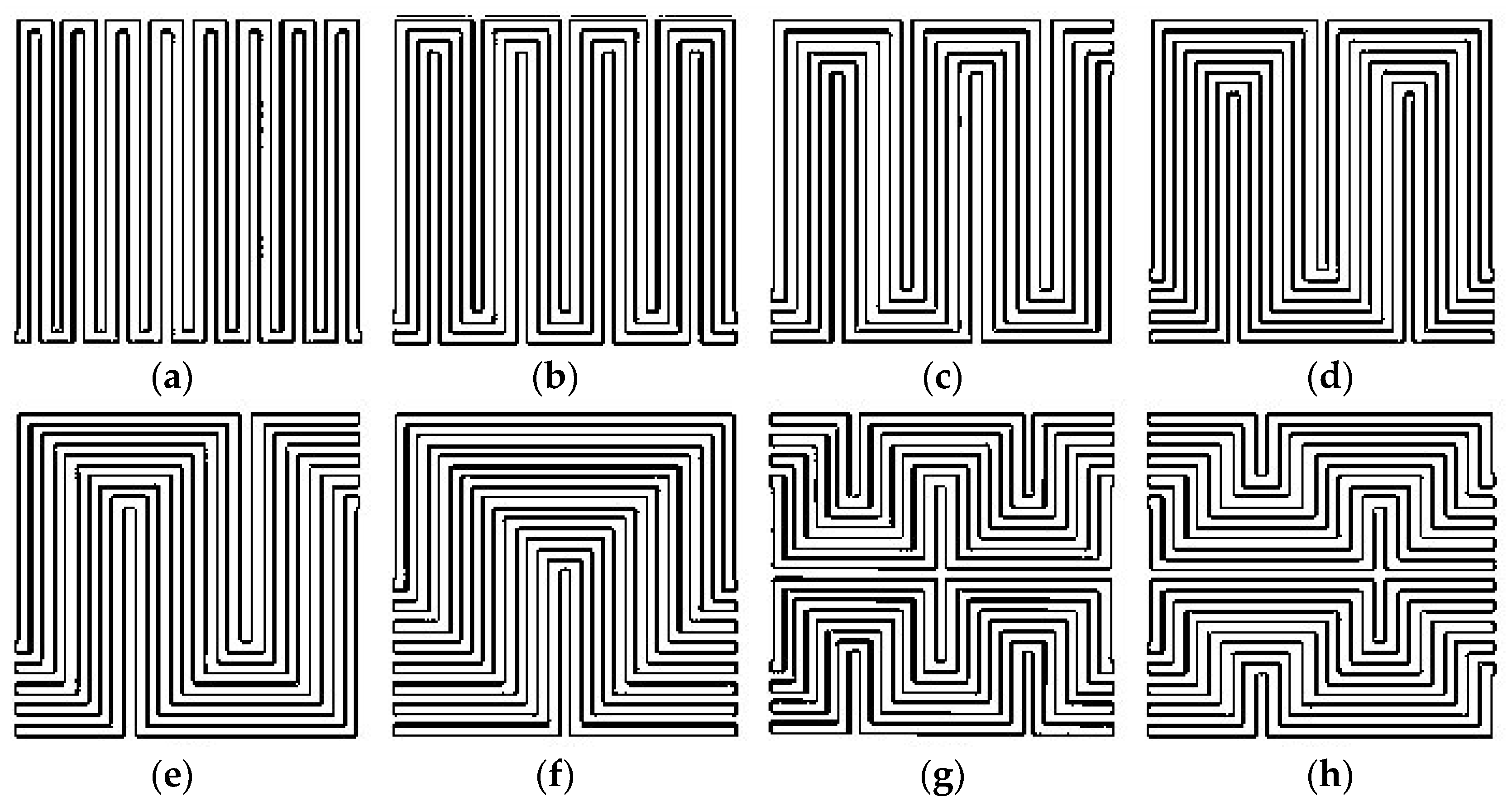
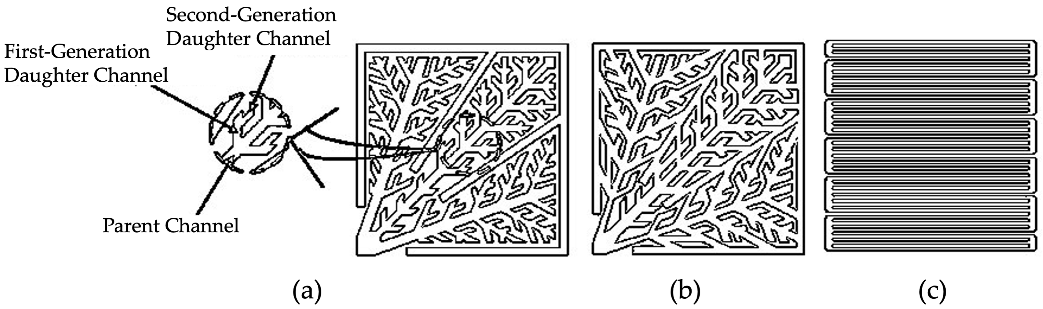
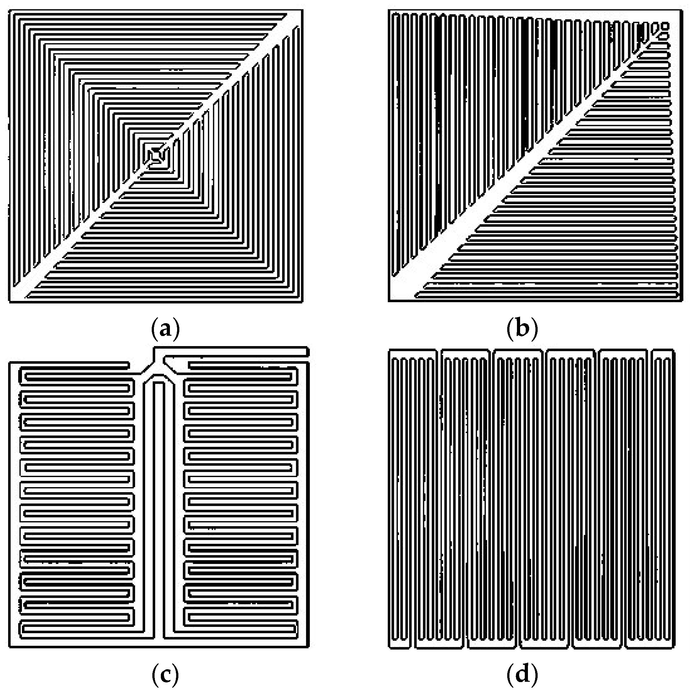
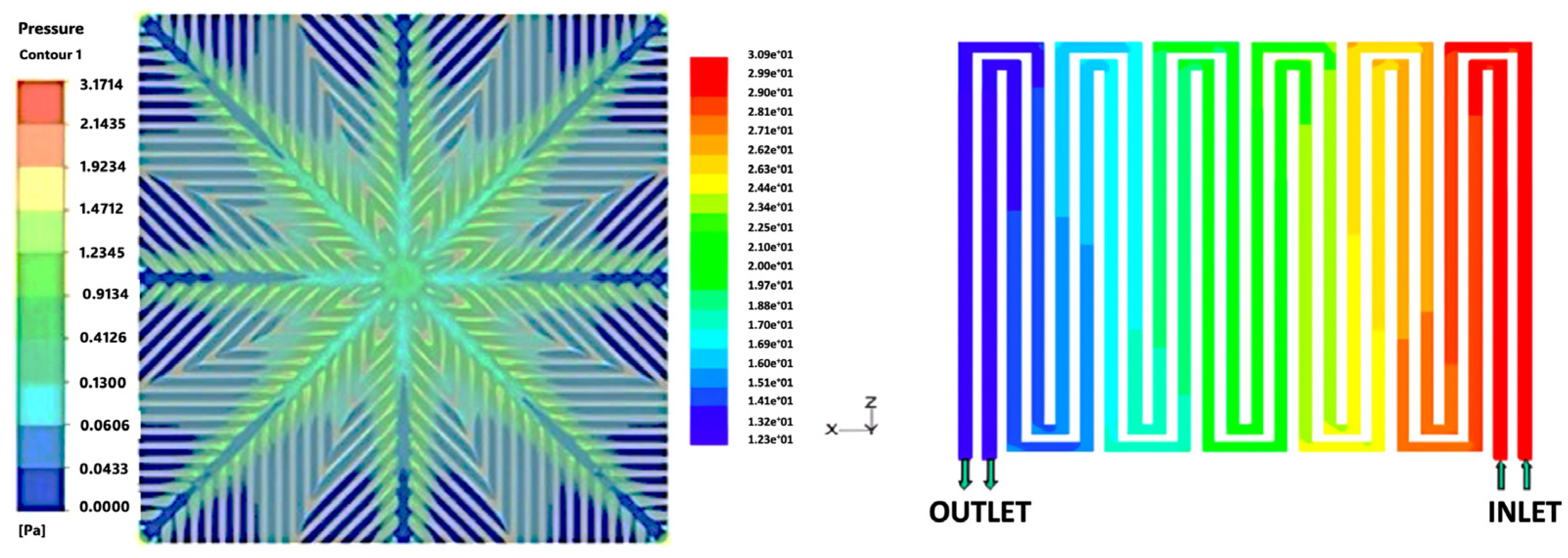
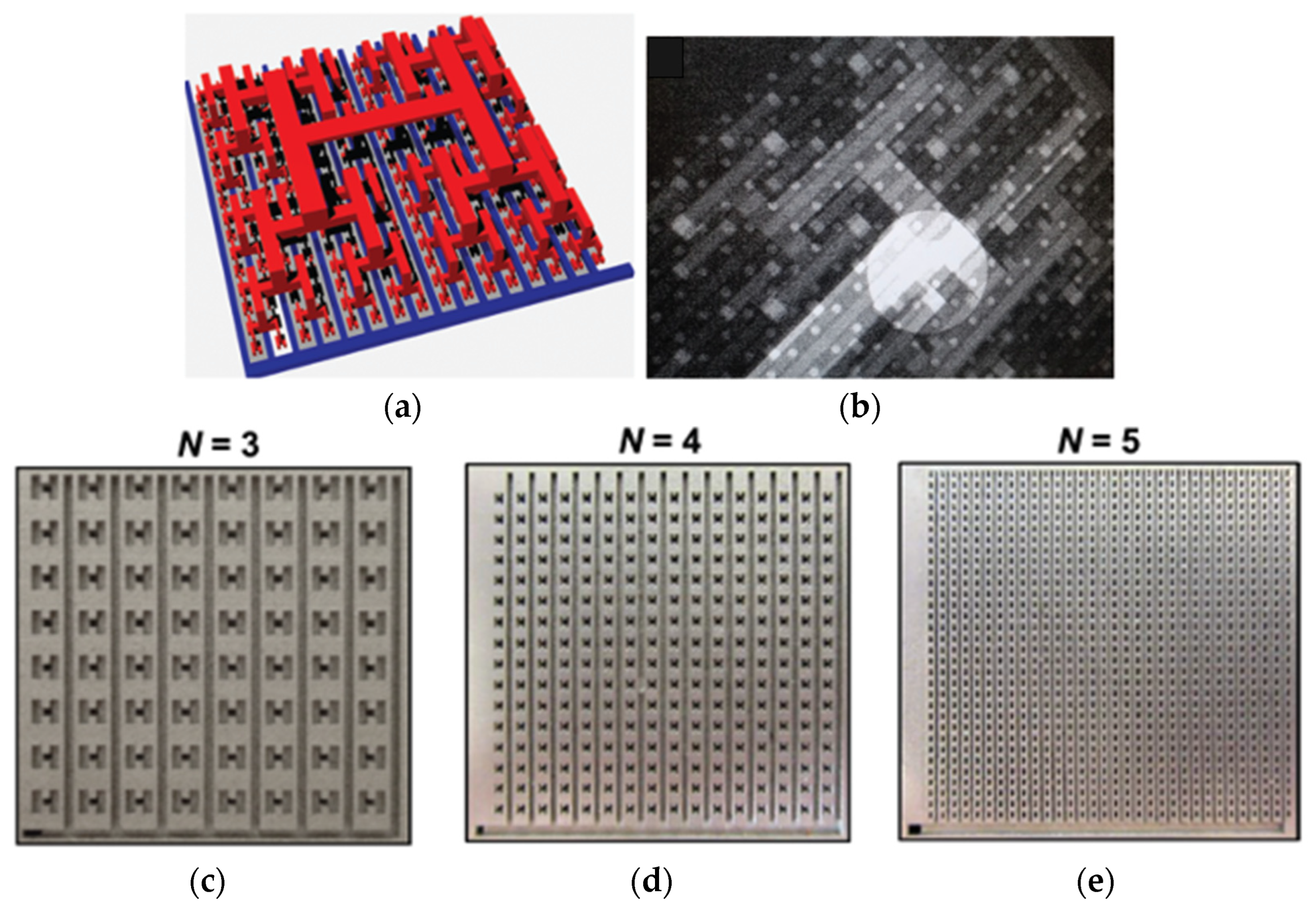


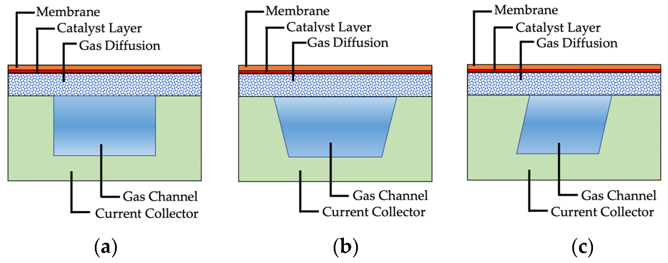
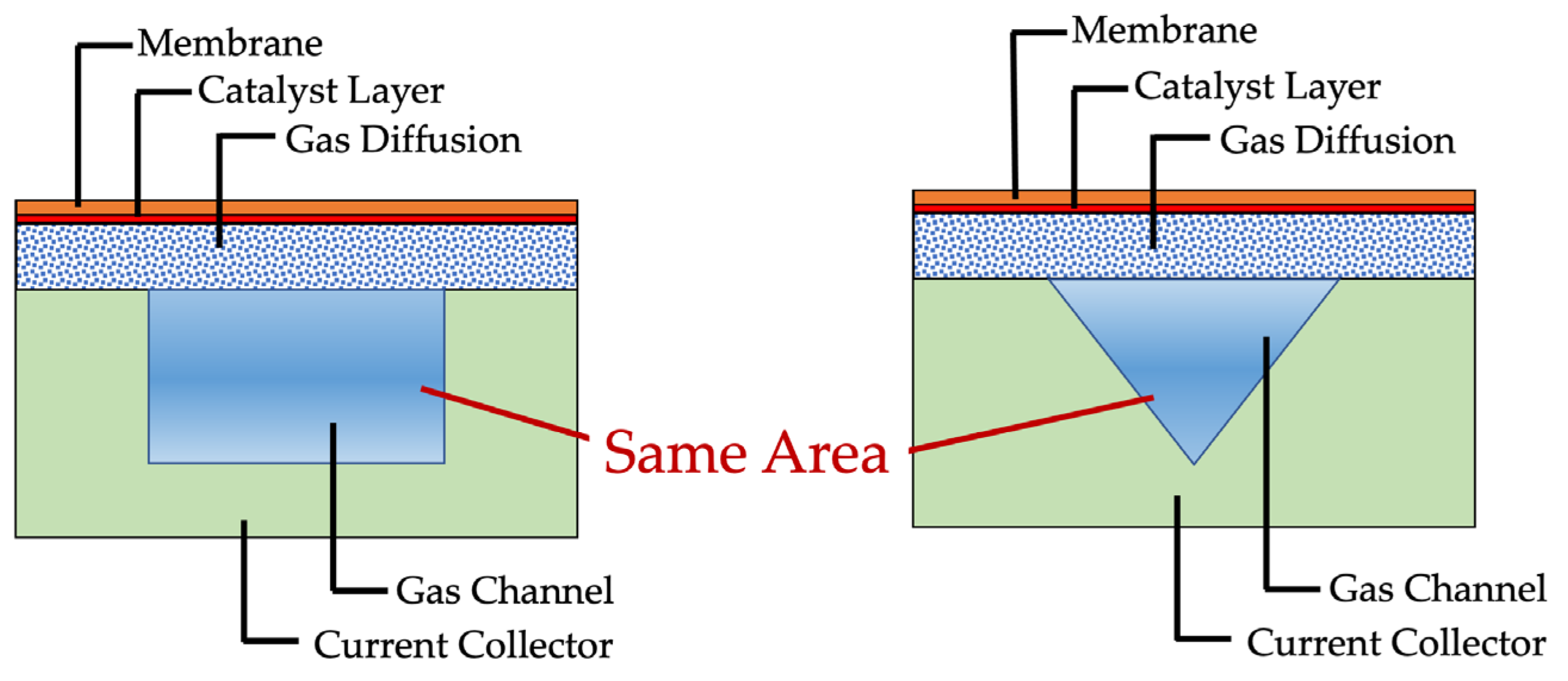
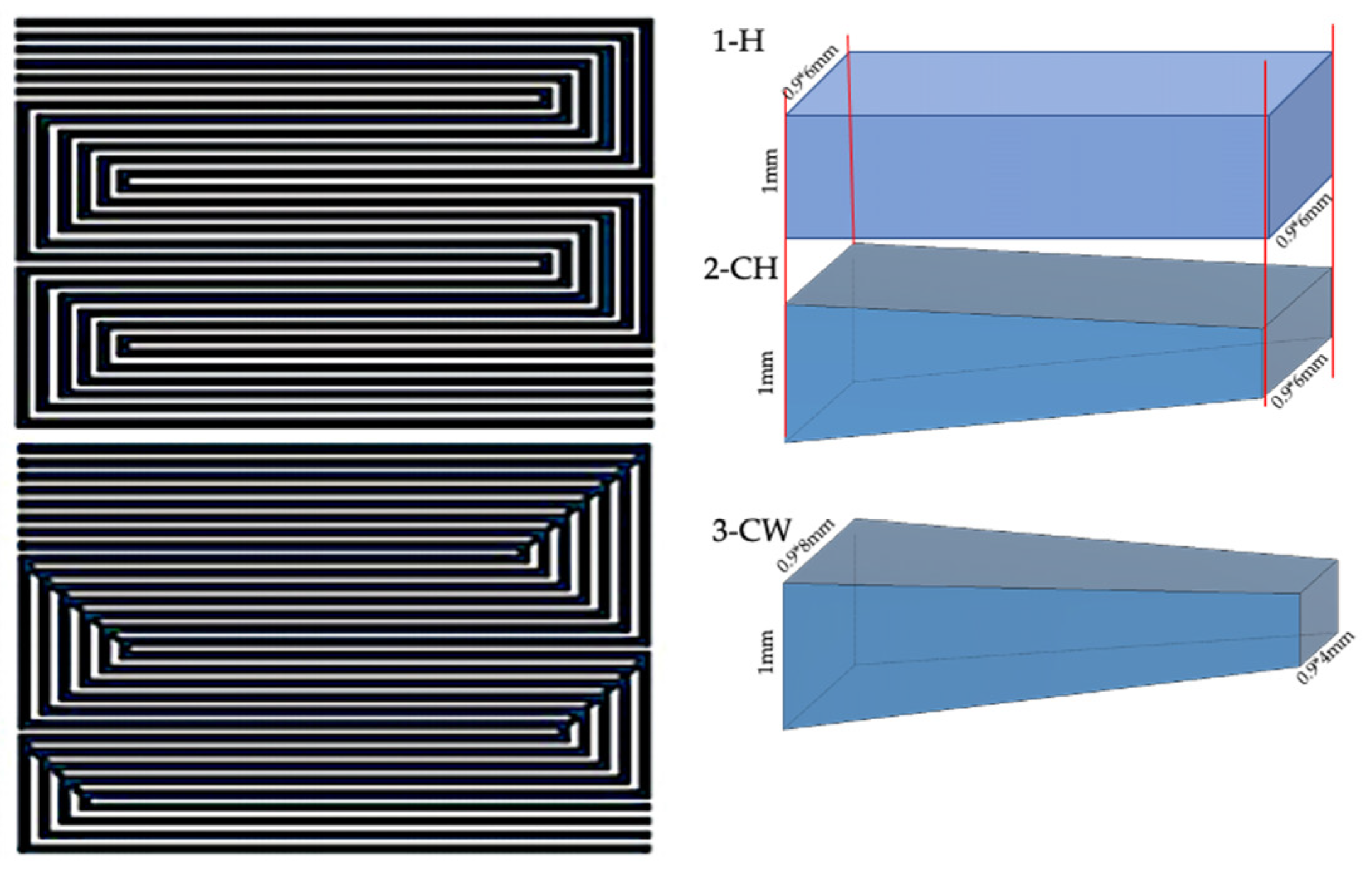
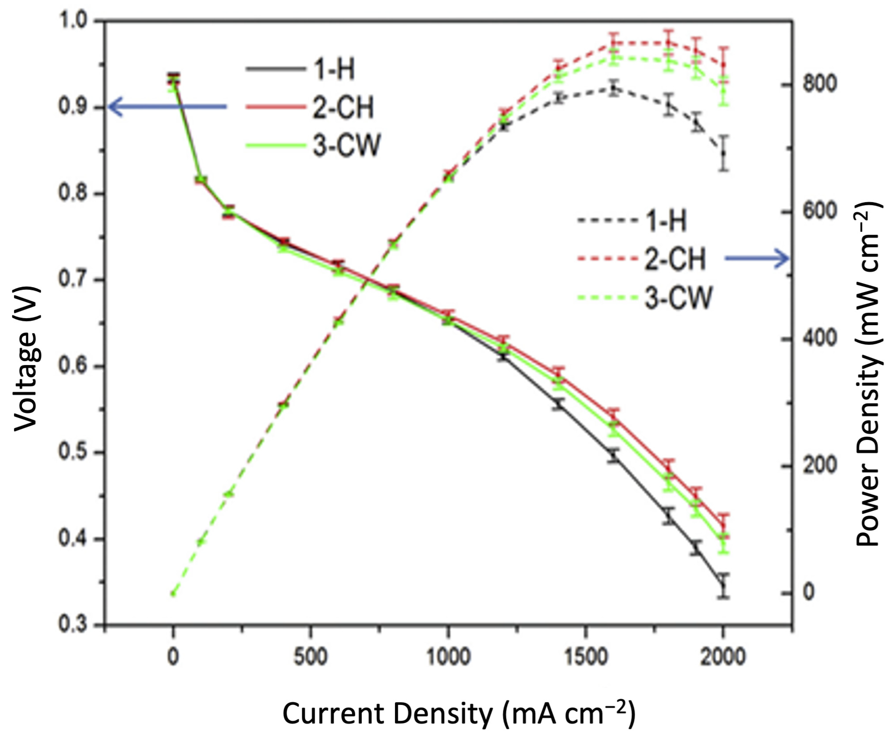
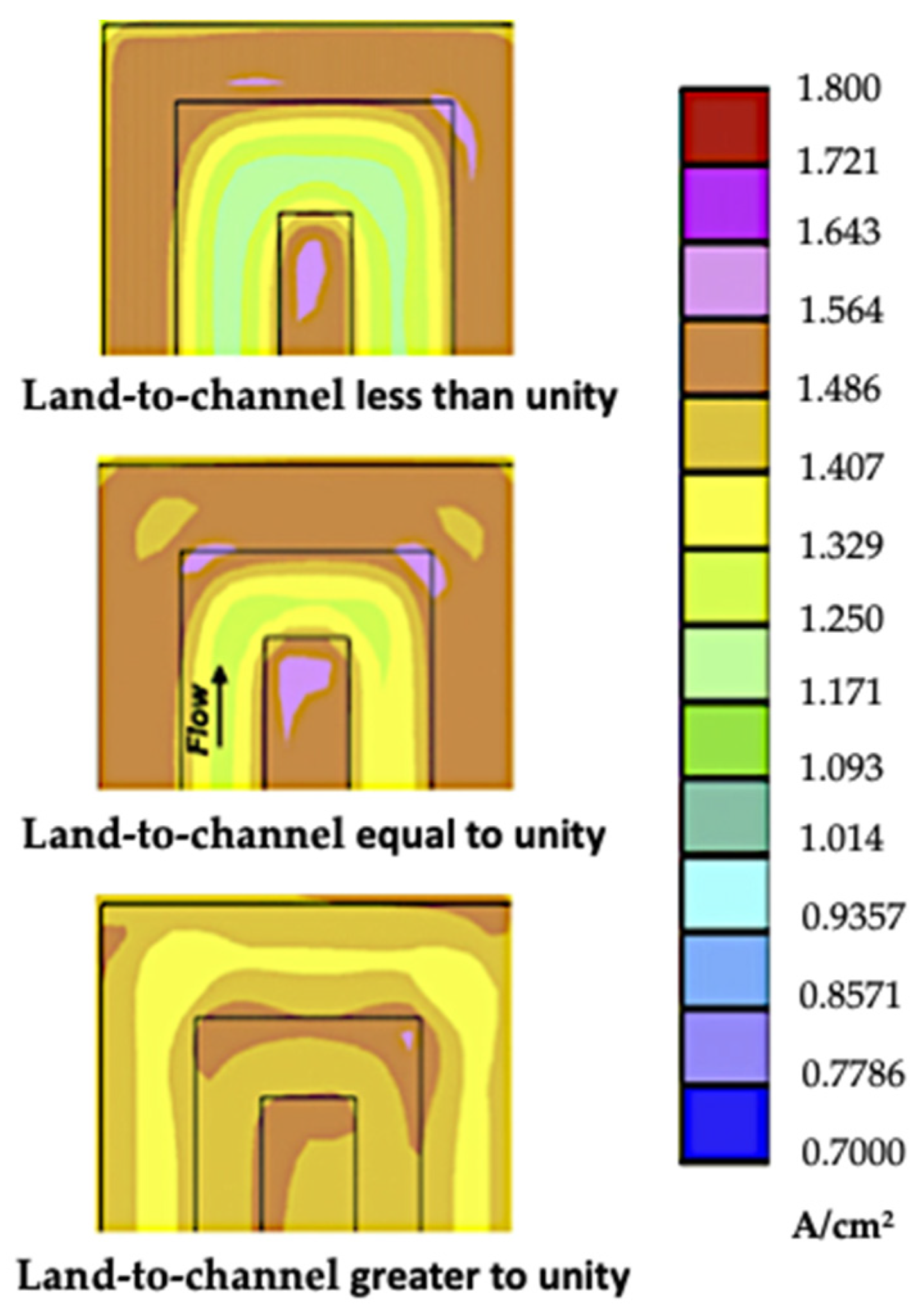
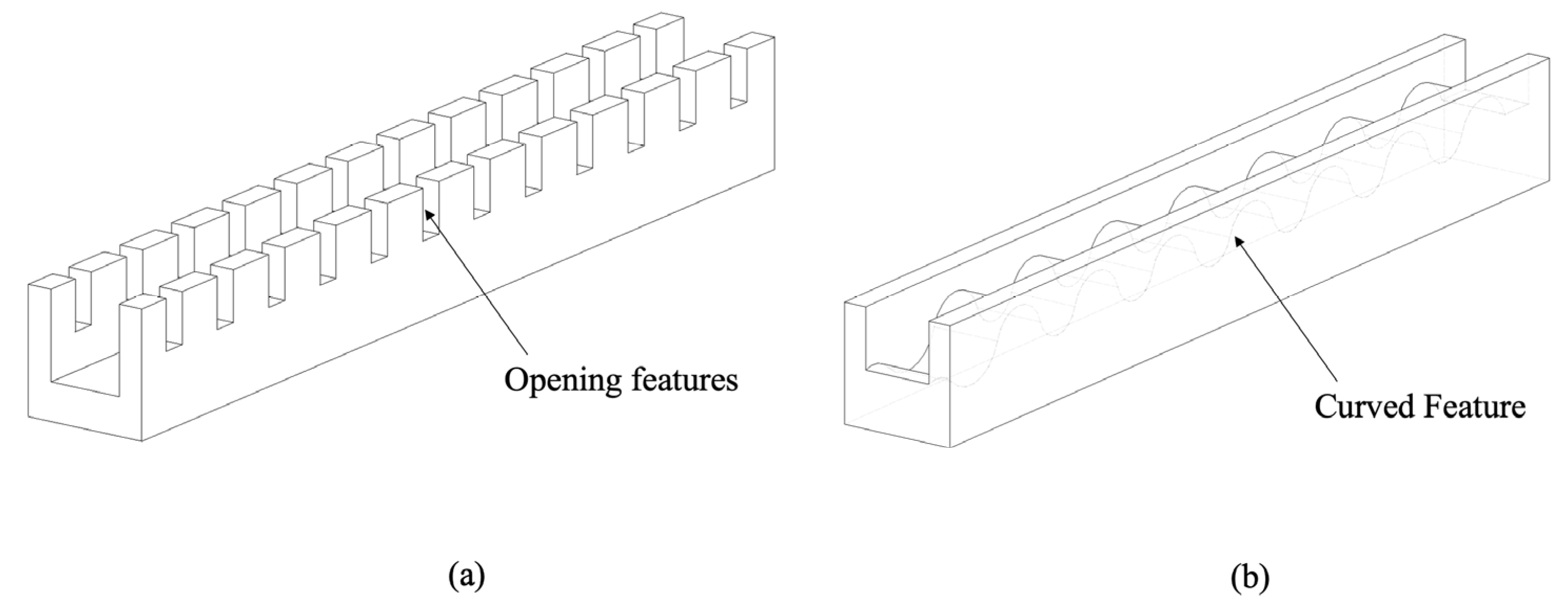

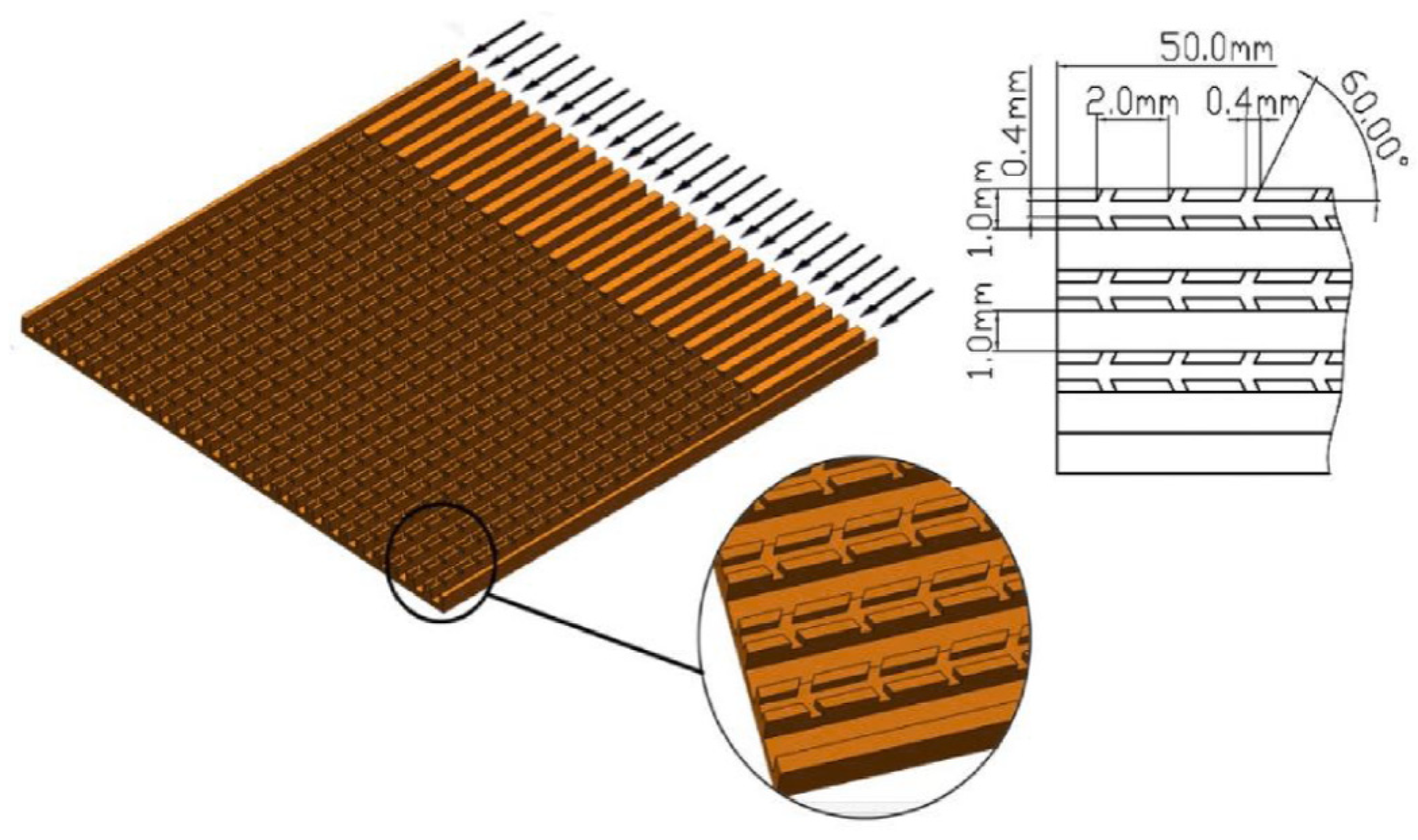

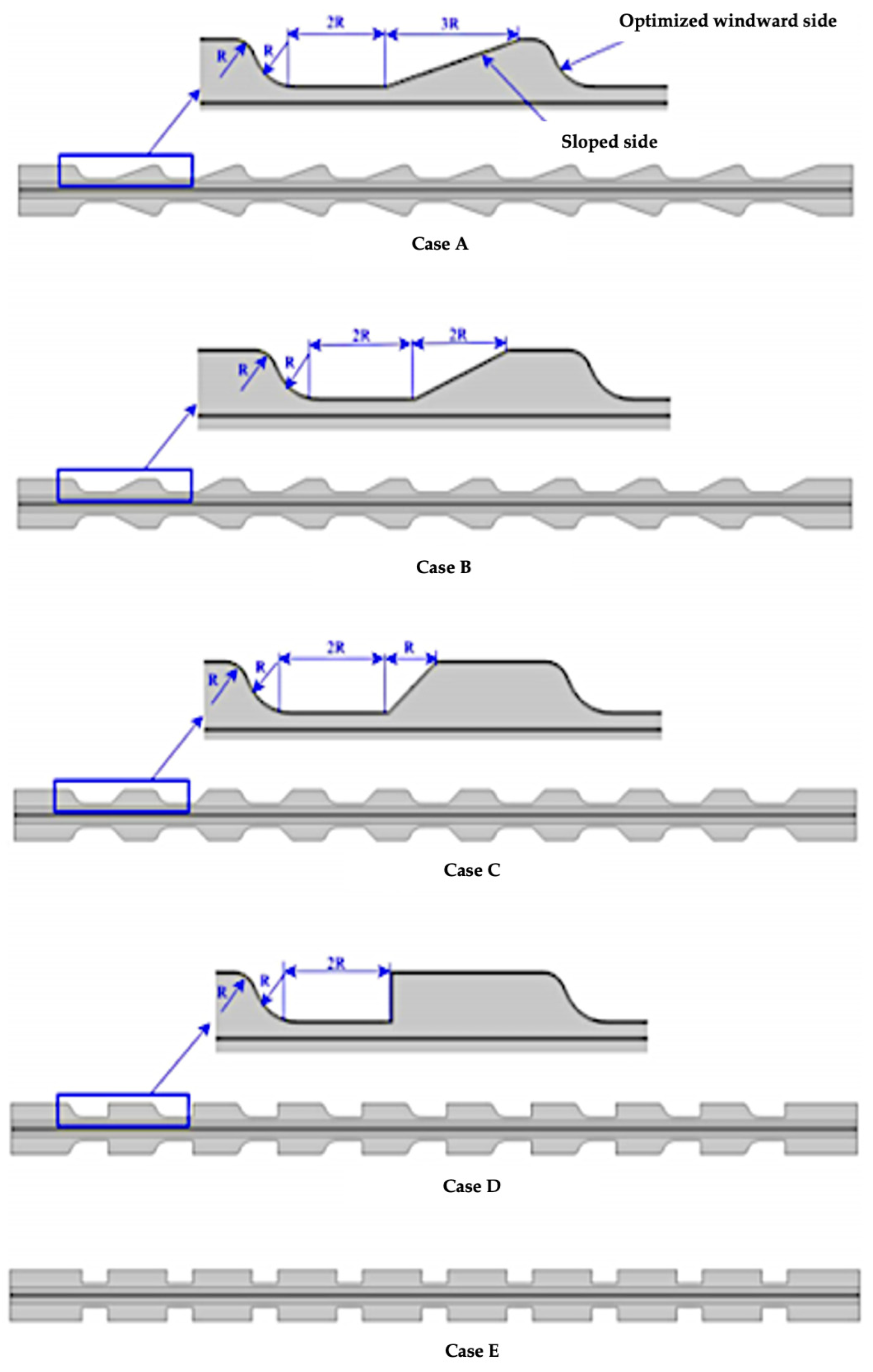
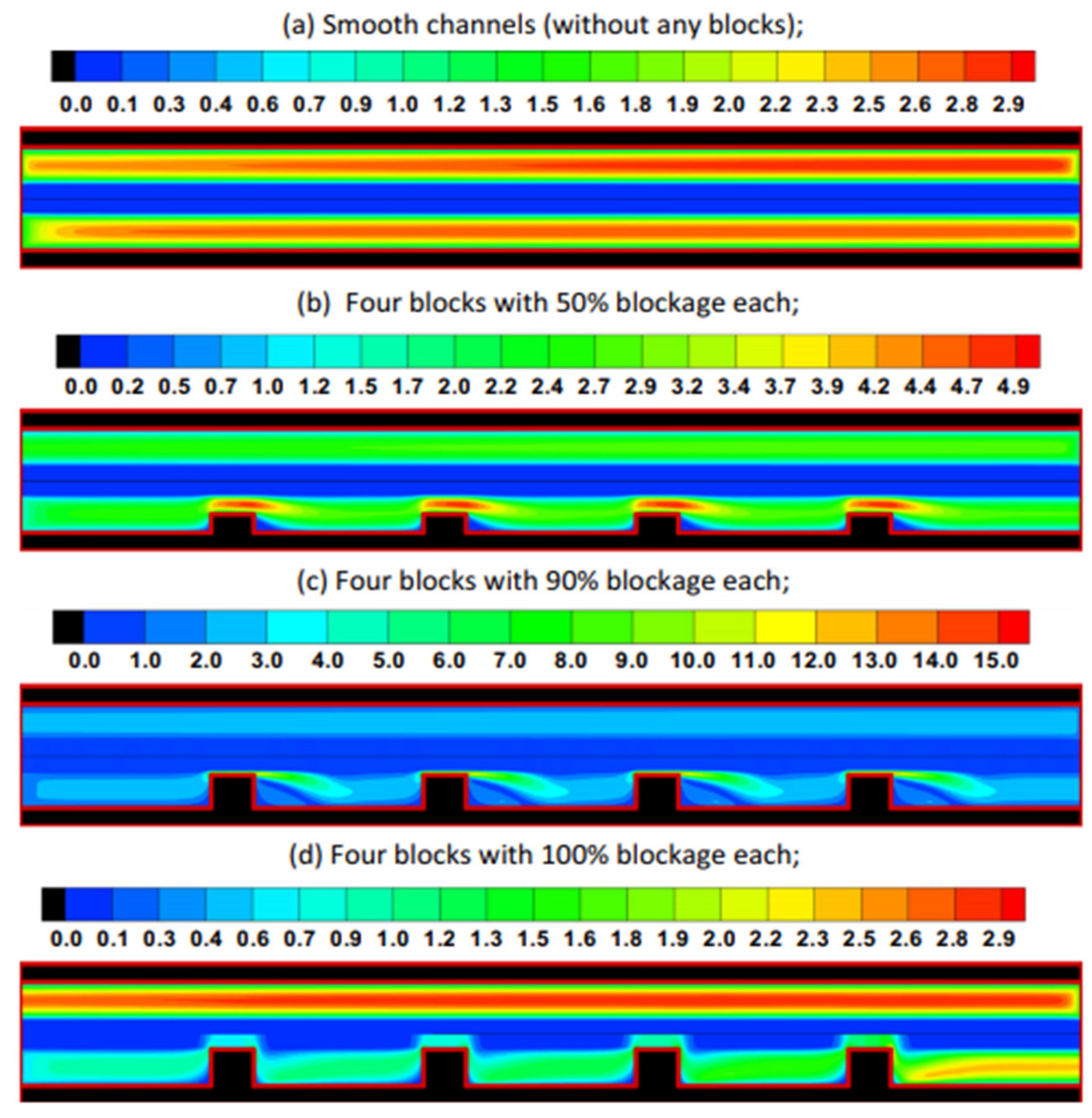
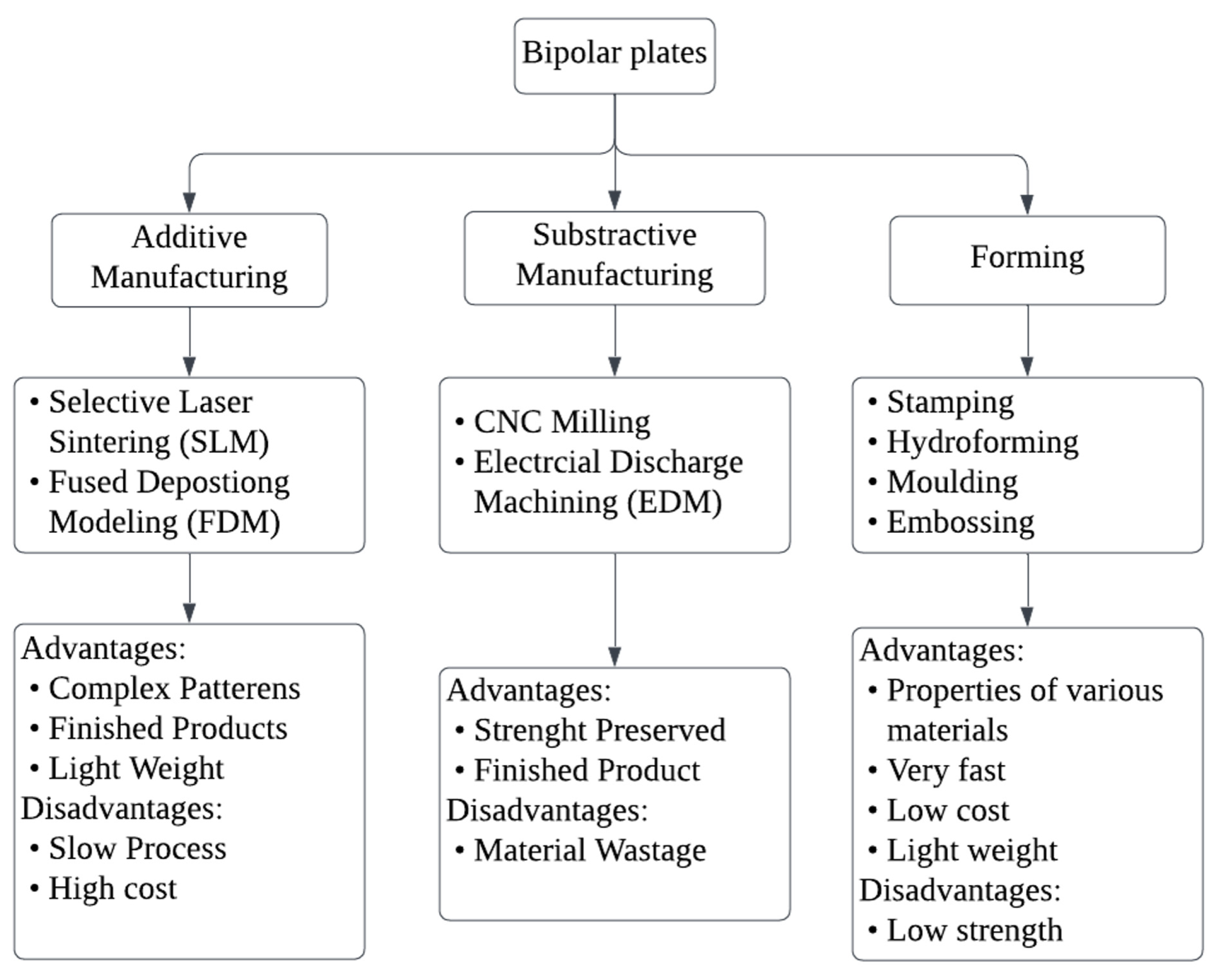
Disclaimer/Publisher’s Note: The statements, opinions and data contained in all publications are solely those of the individual author(s) and contributor(s) and not of MDPI and/or the editor(s). MDPI and/or the editor(s) disclaim responsibility for any injury to people or property resulting from any ideas, methods, instructions or products referred to in the content. |
© 2024 by the authors. Licensee MDPI, Basel, Switzerland. This article is an open access article distributed under the terms and conditions of the Creative Commons Attribution (CC BY) license (https://creativecommons.org/licenses/by/4.0/).