Review

Review of Thermal Energy Storage Materials for Application in Large-Scale Integrated Energy Systems—Methodology for Matching Heat Storage Solutions for Given Applications

1
Group for Energy Storage Technologies, Department of Power Engineering and Turbomachinery, Silesian University of Technology, Konarskiego 18, 44-100 Gliwice, Poland
2
Institute of Energy and Fuel Processing Technology, Zamkowa 1, 41-803 Zabrze, Poland
*
Authors to whom correspondence should be addressed.
Energies 2024, 17(14), 3544; https://doi.org/10.3390/en17143544
Submission received: 24 June 2024 / Revised: 15 July 2024 / Accepted: 16 July 2024 / Published: 19 July 2024
(This article belongs to the Section D: Energy Storage and Application)

Abstract

:
This article is a broad literature review of materials used and defined as potential for heat storage processes. Both single-phase and phase-change materials were considered. An important part of this paper is the definition of the toxicity of heat storage materials and other factors that disqualify their use depending on the application. Based on the literature analysis, a methodology was developed for selecting the optimal heat storage material depending on the typical parameters of the process and the method of heat transfer and storage. Based on the presented results, a solution was proposed for three temperature ranges: 100 °C (low-temperature storage), 300 °C (medium-temperature storage) and 500 °C (high-temperature storage). For all defined temperature levels, it is possible to adapt solid, liquid or phase-change materials for heat storage. However, it is essential to consider the characteristics of the specific system and to assess the advantages and disadvantages of the accumulation material used. Rock materials are characterised by similar thermophysical parameters and relatively low prices compared with their universality, while liquid energy storage allows for greater flexibility in power generation while maintaining the operational parameters of the heat source.

1. Introduction

One of the key elements influencing progressive climate change is human activity related to generating various forms of energy. While it is known that parts of the world are making significant efforts to reduce this impact, there seems to be much to be done. The effect of the Kyoto Protocol on the development of low-carbon technologies has been significant, with the production of electricity from nonrenewable sources reduced by about 36%, and the amount of energy generated from renewable sources increasing by up to 60% [1]. Despite successive international efforts (the Paris Agreement), there is further demand for increased efforts in implementing zero-emission technologies.
The challenges posed by weather-dependent energy sources and the need to regulate existing power systems indicate the need to seek energy storage solutions in every possible form [2]. One of the technologies presenting the greatest potential for application in systems with a wide range of capacities and applicability is thermal energy storage. The areas of low power and low capacity are relatively well recognised, with the common use of short-term sensible heat storage in domestic heating systems [3]. The situation differs for large-scale systems, where power and storage capacity present significant technological challenges. In addition, it should be taken into account that in large-scale systems, another engineering problem may be the heat transfer technology, limiting the rate of charging or discharging the storage, and this may result not only in problems of regulation and control of the energy system itself but also affect the actual applicability of the technology, even despite the promising capacity aspect. Nevertheless, the use of thermal energy storage by enabling the hybridisation of available energy systems and increasing their operational flexibility has a positive impact on both energy security and the scale of emissions, as well as additional opportunities to increase financial viability due to price arbitrage.
This review undertakes a detailed discussion of the available thermal storage materials, focusing on the safety of use and the methodology for selecting a thermal storage material depending on the type of energy system. Based on the literature analysis, a solution was proposed for three temperature ranges: 100 °C (low-temperature storage), 300 °C (medium-temperature storage) and 500 °C (high-temperature storage). For all defined temperature levels, it is possible to adapt solid, liquid or phase-change materials for heat storage. However, it is essential to consider the characteristics of the specific system and to assess the advantages and disadvantages of the accumulation material used. Heat storage materials were analysed in terms of thermal properties, physical properties, economic factors and chemical properties. Based on the analysis performed, it was shown that rock materials such as basalt, granite or sandstone are most often proposed in heat storage systems. Such solutions were used within solar thermal systems and compressed gas energy storage systems. Rock materials are frequently used in heat storage processes due to their low prices and universality. It has been shown that the utilisation of sensible heat storage in liquids is a favoured approach in many systems, including systems where the heat transfer fluid is the primary circulating medium. It has been also demonstrated that materials designated as phase-change can also function as high-temperature sensible heat storage fluids due to their capacity to accommodate a significant temperature range between the melting point and the maximum operating temperature. Detailed descriptions and results are presented in the further sections of this paper.
This article is structured as follows: Section 2 defines the basic methods of sensible and latent heat storage. Section 3 presents a detailed methodology for evaluating storage materials in terms of their fundamental thermophysical, chemical and economic parameters. Section 4 reviews heat storage methods and materials used in large-scale energy storage and power generation systems. Section 5 presents the results of a literature review of materials typified for large-scale heat storage according to the methodology presented previously. Section 6 summarises the results and observations.

2. Classification of Heat Storage Methods

Heat storage can be defined in accordance with the basic diagram in Figure 1.
The classification of heat storage into sensible and latent heat is directly related to the response of the storage material to an external heat flux. Sensible heat storage can be achieved using both liquid- and solid-phase materials. Latent heat is stored during the phase change of a material and can be transferred during solid–liquid, liquid–gas and solid–solid [4] transformations. Figure 2 shows the difference between sensible and latent energy storage, which is derived directly from the relationship between the temperature increase in a storage material and the heat stored.
The process of sensible heat storage in a nonadiabatic system is characterised by a continuous change in the temperature of the storage material as the amount of energy stored changes. This can be described by Equation (1):
Q s = T i T f i n m s m · c p s m · d T = m s m · c p s m · ( T f i n T i )
where Q s is the amount of heat stored, m s m and c p s m are the mass and specific heat capacity of the storage material respectively and T i and T f i n are the initial and final temperatures of the storage material. In a theoretical adiabatic system, there will be natural heat conduction and convection. This is a consequence of the temperature gradient of the storage material. Energy dissipation will result in a decrease in the maximum temperature for the same accumulated energy. A decreasing thermal potential will be observed, which corresponds to a loss of exergy.
Heat storage in liquids is characterised by the use of HTFs (Heat Transfer Fluids) as a direct heat-absorbing storage medium in an exchanger [5]. For this purpose, two heat storage tanks are proposed—one with a cold liquid and one with a hot liquid—with the medium itself flowing through the system depending on the type of operation. In large-scale systems, liquid heat storage is proposed in coal-fired and nuclear power plants to increase the flexibility of electricity production, as well as in solar thermal systems.
The main components of high-temperature (>120 °C) PCMs (phase-change materials) are inorganic salts. Due to their high melting points and low heat of fusion, pure salts have limited applications [6]. The most common are mixtures of inorganic salts, usually binary or triple salts, which are often eutectic mixtures (lower melting point of the mixture than of the individual compounds). Due to their low cost and high melting points, mixtures based on metal chlorides and fluorides (K, Li, Na, Mg, Ca, Mn, Zn) have been widely studied for use as PCM compounds [6]. In addition, hydroxides, nitrates and carbonates (mainly Na, K, Li, Na, Ca) are also components of many PCMs. Carbonates are mainly used in PCMs with high melting points, i.e., >400 °C. Commercial salt mixtures used as heat transfer fluids and PCMs are solar salt (60% NaNO3, 40% KNO3), HITEC (40% NaNO2, 7% NaNO3, 53% KNO3) and HITEC XL (45% KNO3, 7% NaNO2, 48% Ca(NO3)2) [7].
When selecting the PCM, it is necessary to consider a number of parameters, i.e., chemical properties (corrosivity, chemical reactivity, decomposition temperature), thermal properties (phase-change temperature, latent heat, thermal conductivity, specific heat capacity, etc.), physical (density and viscosity) and economic factors (availability and cost). Nevertheless, in the initial selection, the operating temperature and heat of fusion are key parameters. The operating temperature is the temperature range in which the PCM can be used. It includes the melting point and the maximum temperature above which the PCM decomposes. It is also recognised that the maximum operating temperature (stability temperature) is one at which the mass loss of the PCM is in the range of 3–5% of the initial weight [8,9]. The heat of fusion, in turn, determines the capacity of the energy storage; the higher it is, the more energy can be stored. Related to these parameters are material density and specific heat, which together allow the conversion of volumetric energy density. This is a parameter that directly indicates what the necessary storage volume (for PCM) required is to store a given amount of energy.
The process of latent heat storage involves a phase change in the storage material as a result of heat input or output from the system. The phase change takes place at a relatively constant temperature (Figure 2), which makes it possible to maintain a satisfactory HTF temperature for a defined period of time. The accumulated heat Q P C M during the process shown in Figure 2b can be described as follows [10]:
Q P C M = T i T m m P C M · c p s P C M · d T + m P C M · L + T m T f i n m P C M · c p l P C M · d T                = m P C M · c p s P C M · T m T i + m P C M · L + m P C M · c p l P C M · ( T f i n T m )
where m P C M is the mass of the phase-change material, c p s P C M and c p l P C M are the specific heat capacity of the accumulation material in the solid and liquid phases at the average temperature, respectively, T m is the melting point of a phase-change material and L is the heat of fusion.
A common technology for sensible and latent heat storage is the packed bed method. Heat storage in porous beds involves direct contact between the heat transfer fluid and the storage material in the form of a column stacked with bulk material or PCM-filled capsules, with the spaces in between filled with heat transfer fluid. The porous bed sensible heat storage systems proposed in the literature are mainly based on natural, commonly available rock materials. Such a solution guarantees a wide operating range due to the temperature and high pressure resistance of the energy storage system, as well as a relatively low cost. Figure 3 shows a method for heat storage in a porous bed.
A disadvantage of heat storage in porous beds is the preferred direct contact between the HTF and the storage material, which forces the selection of materials that are inert to each other. During the charging phase, the hot fluid is directed into the packed bed where heat exchange between the HTF and the storage material takes place and T i n > T o u t . Due to the increase in the amount of heat stored resulting in a reduction in the temperature difference between the HTF and the storage material, T o u t increases.
Packed bed heat storage is a popular subject for research, both in terms of interaction with other energy storage systems and basic research into the effect of parameters on TES (Thermal Energy Storage) performance. Zhang et al. [11] investigated a packed bed with cylindrical elements on a small scale. The elements were made of stainless steel, which precludes their use on a large scale due to the potential cost. Their work resulted in a proposed modification of the Ergun equation [12] based on a multivariate experimental analysis that included a change in the slenderness parameter of the elements. The effect of element shape on porous bed parameters was also investigated by Govender et al. [13]. It was found that the particle shape of the accumulation material has a notable impact on the thermal conductivity of the packed bed. Wehinger and Scharf [14] conducted a numerical investigation into the potential contribution of thermal radiation to the heat flux. To this end, they studied heat transfer within the porous bed for different element shapes and different ratios of element diameter to liquid tank diameter. Their findings suggest that thermal radiation may have a relatively high contribution even at low temperatures (below 400 °C).
Furthermore, in-depth research is being conducted in the field of phase-change materials, including the utilisation of sealed containers filled with PCMs in the form of a packed bed [15,16]. Liang et al. [17] presented a tank 0.46 m high and 0.36 m in diameter filled with 55 mm diameter capsules. He et al. [18] conducted an experimental investigation of a heat tank filled with capsules of varying diameters and PCMs exhibiting distinct thermophysical characteristics. The results demonstrate that the energy efficiency of the cycle is 74.2%, while the exergy efficiency is 62.7%. This indicates a reduction in the temperature potential of the stored heat.
Key issues in thermodynamic phenomena and their modelling within porous beds were presented by Kaviany [19]. Models are based on empirically determined correlations for the heat transfer coefficient h s f , determining the intensity of heat transfer between the solid and the fluid. The two-phase Schumann model allows transient heat transfer to be modelled by solving the energy conservation equations for the solid region (Equation (3)) and the fluid region (Equation (4)):
T s t = h s f A 0 ( 1 ε ) ρ c p s · T s T f l
T f t + v f · T f x = h s f A 0 ε ρ c p f · T s T f l
where T s and T f are, respectively, the average temperature of the rock material and the fluid in a heat storage segment of length x , t is the time, ρ c p s and ρ c p f are the density and specific heat capacity of the rock material and fluid, v f is the flow velocity of the fluid and ε is the porosity of the packed bed. A 0 is the heat transfer surface area between the rock and the fluid, defined as
A 0 = 6 · 1 ε D p
where D p is the diameter of the rock particles. The Schumann model is a simplified model that does not take into account a number of factors, including the radial temperature gradient of the material [20]. An extension of this concept is the Continuous Solid Model and the Dispersion-Particle-Based Model. The determination of the heat transfer coefficient h s f based on experimental studies was presented by Wakao and Kaguei [21], who proposed a correlation on the Nusselt number N u according to the following equation:
N u = 2 + 1.1 · R e 0.6 · P r 1 / 3 = h f s · D p k f
where R e is the Reynolds number for the porous zone, P r is the Prandtl number fluid and k f is the fluid conductivity. A correlation on the Nusselt number used to describe heat transfer within a packed bed was also presented by Gunn [22].
The fluid flow through the porous bed causes a drop in fluid pressure. This depends on the storage material. The pressure drop is important for the energy storage system. It affects the pump, compressor and expander capacities, as well as the selection of auxiliary components. The Ergun equation can be used to predict the pressure drop [12]:
p L s = 150 · μ D p 2 · 1 ε 2 ε 3 · v D + 1.75 · ρ D p · 1 ε ε 3 · v D 2
The effectiveness of prediction using the Ergun equation has been proven repeatedly through experimental and numerical studies [11,23,24,25]. The concept of determining the pressure drop of a fluid based on Euler’s number was presented by Feng et al. [26], and its effectiveness was demonstrated on the basis of experimental data developed for this purpose.

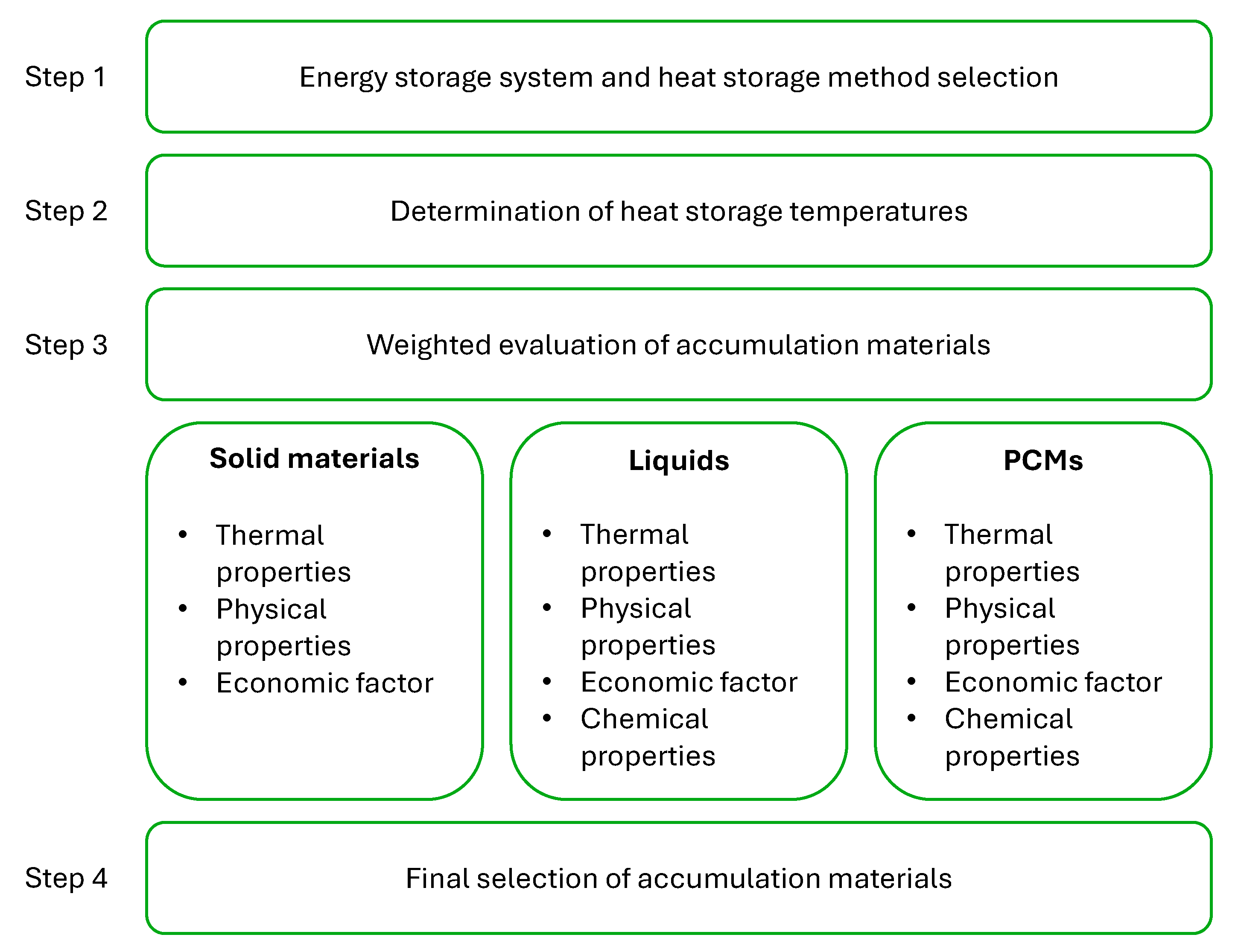
3. Assessment Methodology for Accumulation Materials

Research is based on the concept of a multicomponent integrated energy storage system. Depending on the variant, the energy storage system can use a postmining mine shaft as a reservoir for compressed air [27] or carbon dioxide [28]. A key aspect of the system is thermal integration, whereby heat of different temperature potentials can be used to, for example, support the gas expansion process. Furthermore, the incorporation of heat storage enhances the adaptability of the energy storage system, enabling the intake and generation of electricity to be aligned with prevailing market prices. To assess the suitability of heat storage materials, three temperature levels were delineated: 100 °C (low-temperature storage), 300 °C (medium-temperature storage) and 500 °C (high-temperature storage). These values were employed as reference designations for the suitability of specific materials for heat storage and the thermal integration of energy systems.
The investigation conducted for this article’s purpose was focused on widely accessible natural or processed waste solid materials. This strategy emphasises the economic aspect of an energy storage system and can be an initial step towards reducing the LCOE (Levelised Cost of Electricity) for an energy storage system. The utilisation of solid materials in the form of a packed bed typically determines the use of membrane-free heat exchange between the HTF and the storage material. This results in the utilisation of a packed bed within a single system, rather than as an integrator of multiple systems. The utilisation of the liquid as a heat accumulator enables a comprehensive thermal integration of the disparate initially independent energy generation and storage systems. Low-temperature waste heat can be utilised in another process or provide preheating of the fluid before the main heat exchanger. The fluids and the appropriate selection of pressures in the heat exchangers also lead to heat storage within conventional coal-fired power plants, thereby enhancing their operational flexibility. From a design perspective, the chemical properties of the material are of significant importance, as they determine the strength of the heat exchange surfaces, tanks and pipelines.
In recent years, there has been a significant increase in the development of phase-change materials and their applications in heat storage processes. In addition to thermal and physical properties, toxicity, corrosivity, chemical stability and price are also important in the preparation and operation of a given PCM. It is recommended that the salts contained in the PCM pose a low risk to health and the environment. Desirable characteristics include nontoxicity, nonflammability, chemical stability and low corrosivity, among others.
Figure 4, which presents a scheme for the selection of storage material depending on the chosen method of heat storage, is based on a weighted evaluation method. This method employs a set of main evaluation categories that have been defined.
In the initial stage of the process, a selection of the energy storage system is made and the heat storage method within it is defined, based on the character of heat transfer and the intended application of the stored heat. Once the general assumptions of the system have been established, it is possible to define the temperature ranges over which the heat storage operates. For the purposes of this analysis, an investigation was conducted at three temperature levels: 100 °C, 300 °C and 500 °C. In step three, an evaluation of the storage materials was carried out based on the defined main categories, to which the corresponding expected parameters were assigned. Based on the weighted evaluation, a final selection of accumulation materials that meet the requirements of the energy storage system was made in step four.
The suitability of various materials for heat storage was evaluated in terms of four principal categories of parameters: thermal, physical, chemical and economic. They are presented for solid, liquid and phase-change materials in Table 1. The weight assigned to each parameter utilised in the evaluation by the weighted method is indicated in parentheses.
The weights of each parameter, shown in Table 1, indicate the importance of the characteristic in the overall assessment of the accumulation material. A weight of ‘1’ means that the parameter is considered unimportant for the evaluation of the material and a weight of ‘5’ means that the parameter is crucial for the evaluation of the material. In addition, a disqualifying parameter has been defined—‘operating temperature’ with a weight of 5*. If a solid or liquid material cannot store heat at a given temperature level, it is excluded from further weighting analysis. For PCM materials, due to the specific melting point values, it was assumed that the melting point value must be close to the temperature of the storage level. The weights assigned to specific parameters are values assumed by the authors. It was assumed that the heat capacity and density of the material are crucial for the operation of thermal storage systems, as high values of these parameters allow the construction of TES with smaller volume. From the point of view of building an energy storage system, the cost of the storage material is also an important aspect. In the case of PCM, the thermal conductivity value was also considered a key parameter due to the problems of managing heat transfer in the phase change region. Subsequently, the indicated parameters were evaluated on a scale of 1 to 5, with 1 indicating the least compatible value and 5 indicating the most compatible value, in accordance with the expectations for the specific type of heat storage. Based on the assigned weights for each category and the ratings assigned to the materials, a weighting analysis was conducted, from which recommended materials were selected.
As part of the analysis of thermal properties presented in Table 1, such as specific heat capacity and thermal conductivity, it was decided to only show average values for given temperature ranges (20 °C, 100 °C, 300 °C, 500 °C) in Section 5—Results. Solid storage materials do not have a universal composition, which causes differences in thermophysical parameters that are reported in tests. In the case of liquids and PCMs, the materials are characterised by a fixed composition, which does not cause any discrepancies between the literature data. The following equation was used to calculate the average value for specific thermal parameters for solid materials.
x A V _ T = x 1 T + x 2 T + x 3 T + x n T n T
where x A V _ T is the average value for the given temperature value T, x 1 T , x 2 T , x 3 T , x n T are the values of the analysed parameter for a given temperature from references and n T is the number of the references from which the data were used.
As mentioned, high-temperature PCMs consist mainly of mixtures of inorganic salts. The properties of the individual salts affect the properties of the resulting PCM. As shown in Table 2, salts possess both advantages and disadvantages. For example, fluoride and chloride salts are corrosive [29], and fluorides are also highly toxic. On the other hand, chlorides are a potential substitute for nitrates. Chloride salts are abundant, inexpensive and have good thermal stability [8].
Carbonate salts and their mixtures are characterised by very high thermal and chemical stability. Although carbonates decompose into CO2 when exposed to acids, this does not prevent their use in PCMs. In addition, carbonates do not release toxic gases when heated, unlike chlorides (e.g., ZnCl2, MgCl2). Carbonates of K and Na are also nonhazardous and have low corrosivity. Sodium bicarbonate (baking soda) and sodium carbonate (soda ash) are typical household substances. In the case of nitrite (NaNO2, which is a component of the commercial HITEC system), it should be noted that partial oxidation to nitrate occurs above 350 °C in contact with air [30].
Commonly used sulphates, carbonates, chlorides and nitrates of K, Mg, Na are nontoxic and relatively inexpensive. Lithium salts have a high heat of fusion but are very expensive. Sodium hydroxide, often used in hydroxide salt mixtures with melting points around 300 °C, is highly corrosive and very hygroscopic. However, it is readily available and relatively inexpensive.
From the aforementioned information, it is clear that there is no single, universally applicable parameter that can be used to select a suitable PCM. However, based on our assessment, the primary selection criteria for PCMs can be ranked as follows: (1) adequate operating temperature, (2) high latent heat, (3) low toxicity and corrosivity and (4) price and availability. The price criterion is the least important, as it is not a significant factor during the preliminary research phase. Furthermore, the purchase of chemicals on a large scale is considerably more cost-effective.
It is worth noting that hygroscopicity is not commonly addressed in other papers. However, it has a significant impact on the PCM preparation step—specifically the encapsulation step. Materials that are hygroscopic absorb moisture from the air, and highly hygroscopic materials can even deliquesce, eventually forming an aqueous salt solution (e.g., LiCl, NaOH, ZnCl2, MgCl2). Therefore, it is always essential to thoroughly dry the salt at elevated temperatures and then store it in airtight containers, often filled with additional desiccants. The filling of PCM containers should also be carried out in a moisture-free atmosphere, as the adsorbed water affects the thermal parameters of the PCM [31], including increasing its corrosiveness (especially in the case of chloride salts).

4. Overview of TES Applications and Heat Storage Materials

4.1. Sensible Heat Storage

4.1.1. Packed Bed

Barbour et al. [32] proposed a multivariant concept for an adiabatic compressed air energy storage system utilising a packed bed as TES. The heat storage process enables the avoidance of gas combustion at the discharge stage of the system, thereby reducing greenhouse gas emissions. Basalt grit was employed as the storage material; however, the analytical model presented did not extend to include the detailed characteristics of the packed bed. The maximum temperature achievable in the TES was determined to be 440 °C for the two-stage system and 196 °C for the four-stage system. This is related to splitting the air compression stage with interstage cooling. The exergy analysis showed that the heat tank was responsible for 7% of the exergy loss.
Cheng et al. [24] conducted experimental studies utilising sinter with a density of 3400 kg/m3 and element diameters within three distinct ranges: 10–18 mm, 18–30 mm and 30–40 mm. Details of the sinter used were given by Lai et al. [33]. Their methodology involved the utilisation of ore sinter, which was subjected to testing across a temperature range of 200 °C to 380 °C. The resulting density of the accumulation material ranged from 3600 kg/m3 to 3727 kg/m3, with the irregular shape of the elements leading to a relatively high bed porosity of 0.569 to 0.617. This resulted in a low bulk density. They also highlighted the low cost of the potential heat storage system due to the use of waste material.
Kothari et al. [34] published the results of an experimental and numerical study of a heat storage tank whose accumulation material was magnetite with a density of 4700 kg/m³ in the form of a packed bed with a porosity of 0.36. The rock was characterised by an irregular shape, typical of bulk materials, with diameters ranging from 8 mm to 20 mm. A notable aspect of the study was the scale of the constructed heat tank. The internal tank, filled with magnetite, had a height of 5.32 m and a diameter of 1 m. The heat transfer medium was air, whose maximum temperature during the charging stage was approximately 527 °C. The authors demonstrated an important feature of heat storage in porous materials in terms of heat potential conservation through experimental and numerical methods. During the discharge stage, heat exchange in a two-way column results in a gas with a much lower temperature (as low as 73 K) than the maximum temperature of the rock. Furthermore, it is impossible to maintain a constant temperature course of the regenerated air.
The experimental studies conducted by Ochmann et al. [35] have provided the basis for a series of laboratory and numerical studies. The object of the research is a heat storage tank with a height of 3 m and an internal diameter of 0.219 m, which exhibits a high degree of slenderness. This feature represents a significant novelty among the heat storage systems that have been investigated to date. The particular slenderness of the tank was intended to support the concept of adiabatic energy storage in compressed gases using post-mining mine shafts [27]. The storage material was a basalt aggregate with a diameter of approximately 16 mm, the thermophysical parameters of which were determined by in-house testing using a TCi analyser with an MTPS (Modified Transient Plane Source) sensor. The porosity of the rock deposit was estimated to be 0.38, noting that the porosity distribution is dependent on the proximity to the heat tank wall. Ochmann et al. [36] presented their own numerical model of an adiabatic energy storage system in compressed air operating in a charge, storage and discharge cycle. The heat tank, once again filled with basalt, was modelled using the Schumann equations, resulting in an air temperature of 600 °C. The model was further augmented with compressor and expander operating characteristics that took into account the air pressure drop calculated using the Ergun equation. Additionally, the use of basalt as a heat-accumulating material was also addressed by Nahhas et al. [37]. A significant element of the research was the examination of samples sourced from diverse geographical locations, including Egypt and France. The findings revealed that basalt exhibits structural integrity within a temperature range spanning ambient conditions to 700 °C. It is noteworthy that basalt of Egyptian provenance demonstrated the formation of microcracks during cyclic operation.
Cascetta et al. [38] presented a study of a heat storage tank in which the storage material was alumina with element diameters of 7 to 9 mm, a density of 3550 kg/m3 and a maximum HTF temperature of 300 °C. The porosity of the rock bed was dependent on the distance from the tank wall and ranged from 0.385 to 0.395. Anderson et al. [39] employed alumina at a maximum HTF inlet temperature of 120 °C and an assumed bed porosity of 0.4. Their findings demonstrated that the adoption of temperature-dependent thermophysical parameters for the accumulation material enhanced the accuracy of the numerical modelling. Furthermore, it was demonstrated that the thermal conductivity, k f , decreases with temperature, from 33 W/mK at 20 °C to 6.7 W/mK at 1200 °C.

4.1.2. Liquid

In their study, Kosman et al. [40,41] proposed the use of molten solar salt as a means of increasing the flexibility of conventional coal-fired power plants. The salt, which consists of 60% sodium nitrate and 40% potassium nitrate, has a melting point of approximately 222 °C [42]. Nissen [43] indicated the thermophysical values of the solar salt in a 50%/50% component ratio in the temperature range from 300 °C to 500 °C. The authors of the concept demonstrated that there are four potential routes for integrating a coal-fired power plant and heat storage: (a) via an electric heater powered from a generator; (b) feeding the heat exchangers with secondary steam; (c) feeding the heat exchangers with excess steam; and (d) feeding the electric heater with a generator and renewable energy sources. Figure 5 presents the concept of using an electric heater.
The conclusion of the study is that the flexibility of a potential conventional coal-fired power plant can be increased through the use of heat storage. This leads to the possibility of adapting its operation in the face of increasing penetration of energy systems by RES (renewable energy sources).
The concept of utilising heat storage as an intermediary circuit between the nuclear island and the turbine island in an SMR (Small Modular Reactor) from Kairos Power has been presented by Bartela et al. [44]. Additionally, the potential for solar salt, in conjunction with HITEC ternary salt mixture (53% KNO3, 7%NaNO3 and 40% NaNO2), has been indicated. The maximum proposed storage temperature was 600 °C, with the lowest temperature being 300 °C, which corresponds to the characteristic temperatures defined for this type of reactor. Furthermore, the possibility of using heat storage processes in collaboration with nuclear reactors has also been described by Al Kindi et al. [45], Denholm et al. [46] and Kluba and Field [47]. All authors highlight the significant advantages of adjusting the steam turbine load in accordance with customer demand while maintaining the thermal output of the reactor at a constant level. Zou et al. [48] conducted an experimental investigation of the HITEC salt with Ca(NO3)2, resulting in a composition of 16.67% Ca(NO3)2·4H2O, 44.17% KNO3, 5.83% NaNO3 and 33.33% NaNO2. The operating temperature for this compound was determined to be in the range of 200 °C to 565 °C, which is a larger range than the standard HITEC salt (200 °C to 450 °C) and solar salt (290 °C to 565 °C).
Furthermore, the utilisation of heat storage was proposed and employed in large-scale and domestic solar thermal systems. Guo et al. [49] conducted an analysis of a district heating system comprising a central low-temperature (below 100 °C) heat storage tank that stores solar heat. The circulating medium in the system is water, which ensures a relatively low installation cost. In addition to the central TES, the integration of individual domestic heat storage tanks has been proposed. Hailu et al. [50] presented an existing domestic solar thermal storage system that employs a mixture of water and glycol as the heat transfer fluid, thereby expanding the operational temperature range of the system. The concept also encompasses seasonal heat storage in sand, rendering it applicable to a wide range of industrial applications.
Organic thermal oils are particularly popular in industrial applications due to their much higher boiling point at atmospheric pressure [51]. However, one disadvantage is that they are environmentally toxic [52]. Kluba and Field [53] proposed the use of Therminol 66 synthetic oil in their concept for heat storage in the nuclear cycle. The maximum temperature achieved on the energy storage side was 125 °C by heat exchange between steam and thermal oil. The temperature applicability of Therminol 66 was determined to be in the range of −3 °C to 345 °C [54]. Stanek et al. [55] presented the concept of a large-scale parabolic trough collector (PTC) system consisting of 90 absorbers, each 1 m long. The authors demonstrated that Therminol VP-1, with an application range of 12 °C to 400 °C, can be used in the food [56] and processing [57] industries for high heat storage temperatures.

4.2. Latent Heat—Phase-Change Materials

Goel et al. [58] stated that phase-change materials are often proposed as heat accumulators in solar thermal systems. However, their use is associated with system management issues due to the lack of stability and performance resulting from the low thermal conductivity of the PCM or their low maximum operating temperature, among other factors. Reddy et al. [59] present the concept of utilising PCMs and latent heat storage within a concentrated solar power (CSP) system. A series of numerical investigations were conducted to study the effects of different geometries of the heat exchanger and heat storage in the form of a system of inner tubes and one outer tube. The PCM, which was hydroquinone, had a thermal conductivity of 0.1 W/mK and a melting point between 168 °C and 173 °C. The results indicate that increasing the heat transfer areas between the HTF and the PCM had a positive effect on the regularity of the melting and solidification process, which is tantamount to improving the efficiency of the heat store. Ray et al. presented a basic numerical investigation into the use of silicon and NaNO3 as potential heat storage materials for high-temperature systems. Their melting points were 1425 °C and 317 °C, respectively. Silicon has high thermal conductivity, but it is difficult to assume that a material with such a high melting point would be widely used in energy storage systems due to the strength of other materials.
Jayathunga et al. [60] developed a summary of phase-change materials dedicated to CSP. An important aspect of their work was to demonstrate that as the phase-change temperature increases, the latent heat of reaction per mass of PCM decreases. This leads to the direct correlation that the higher the desired operating temperature of the system, the larger the TES tank must be. They corroborated the conclusions of other authors regarding the low thermal conductivity values of phase-change materials. Furthermore, the integration of CSP into the TES has been demonstrated to result in efficiency gains of up to 43%, with an average value of 25% to 28%. Additionally, the utilisation of renewable energy sources in conjunction with a heat storage tank has the potential to reduce the cost of electricity generation by up to 0.1 USD/kWh, with a current weighted global average of 0.108 USD/kWh.
Munir et al. [61] presented the findings of an experimental study on the viability of a heat storage system equipped with a Scheffler concentrator for agricultural applications. The phase-change material utilised in the study was paraffin wax (RT70HC), which exhibited a melting and solidification temperature range of 69 °C to 71 °C and a reference thermal conductivity of 0.2 W/mK. The heat reservoir comprised a bundle of tubes through which Fragoltherm Q-32-N was used as the HTF at different mass flows. The bundle of tubes was surrounded by a phase-change material, and the entire tank was insulated. The authors confirmed that the TES system with phase-change material exhibited low performance due to the low thermal conductivity and the solidification effect near the heat transfer surface with HTF.
Yu et al. [62] presented a concept of a CAES (compressed air energy storage) system utilising phase-change materials in the form of a packed bed. The system comprises a two-stage compressor and a two-stage air expander. One TES tank serves as an air cooler/regenerator between the machine stages, while the second TES tank is located directly before/after the compressed air reservoir. A schematic of the system is shown in Figure 6.
The authors demonstrated that the temperature of the regenerated air during the discharge stage exhibits a transient stabilisation for approximately 50% of the discharge stage duration. Subsequently, an intense temperature decline is observed, from approximately 257 °C to 27 °C, which will significantly impact the energy efficiency of the air expander. The optimal combination of different PCMs in the TES results in a round-trip system energy efficiency of 73.4%.

5. Results

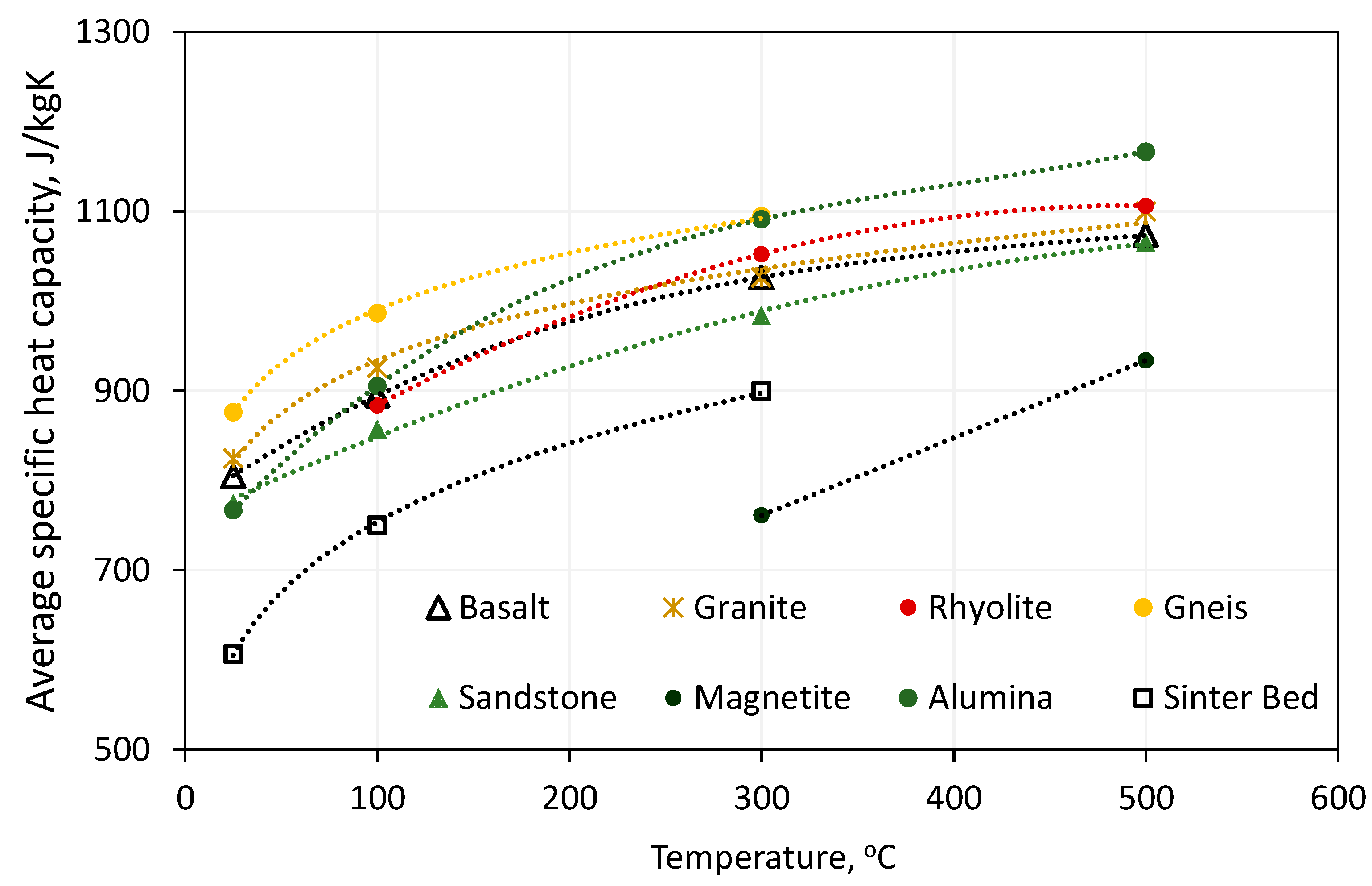
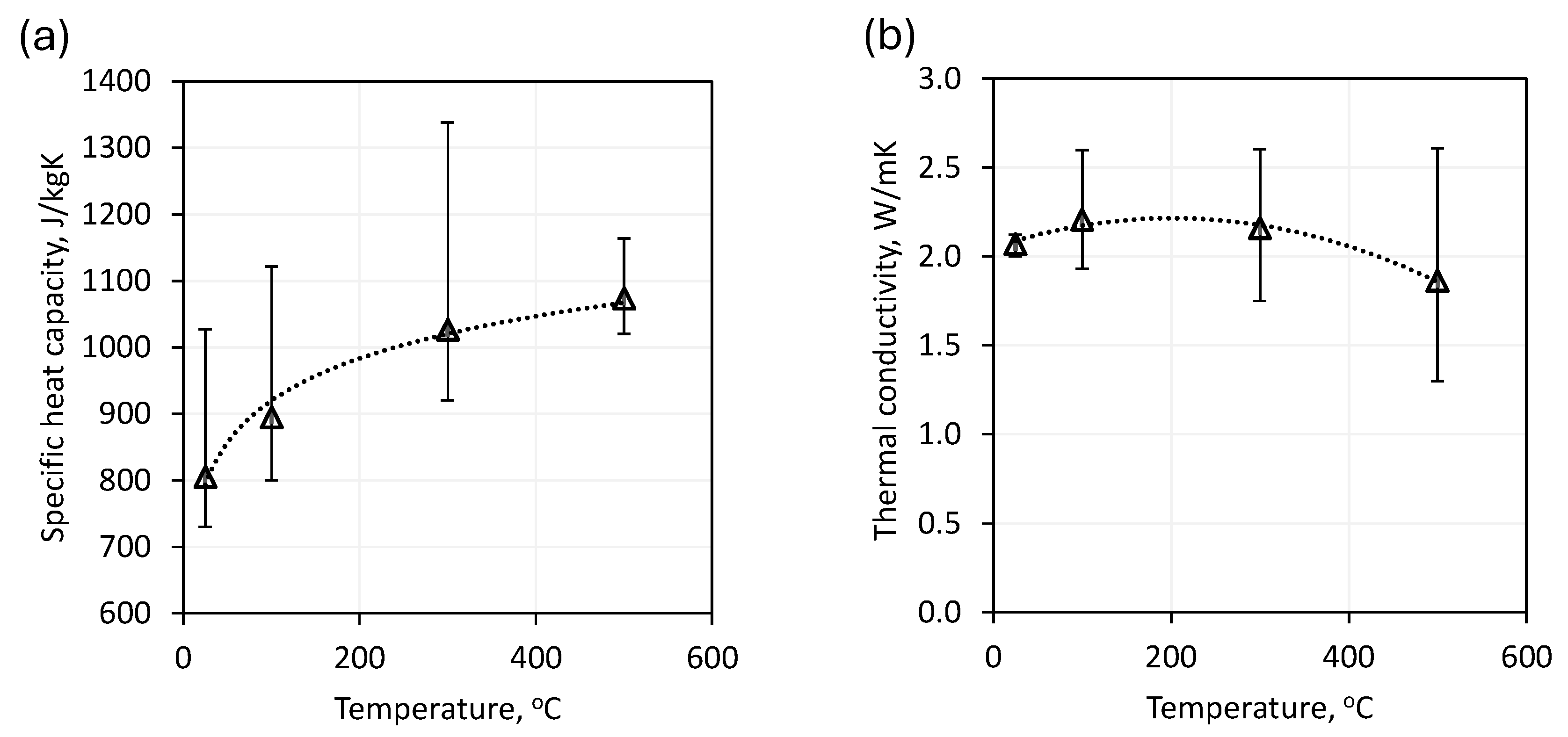
5.1. Solid-Phase Materials for Sensible Heat Storage

A summary of the solid materials reviewed in the literature for sensible heat storage was prepared on the basis of the methodology presented in this paper. Due to the large number of literature sources, the values presented in Table 3 are the average values from all values presented in the references. The parameter values were read for a reference temperature of 20 °C. In the case of deviations from this rule, due to the way the data are presented, the relevant reference temperature for a specific case is given in brackets.
The data presented allow the conclusion to be drawn that the natural rock materials used or proposed as potential heat accumulators in TES have similar thermal conductivity values, with a range of 2 to 6.1 for reference temperatures. A significant difference is observed in the thermal conductivity of alumina, which is an order of magnitude (33.4 W/mK) higher than the other materials. It is important to note that the parameters indicated in Table 3 pertain to the specific properties of the rock material. Consequently, the calculation of the requisite volume of the heat tank must incorporate the porosity of the rock bed or the volume occupied by the channels of the flowing HTF. In the context of porous deposit modelling, the effective thermal conductivity, which takes into account the frequency of contact between deposit elements, is also introduced, as is the value of the heat transfer coefficient of the HTF. However, Diaz-Heras et al. [81] demonstrated that including the value of the effective thermal conductivity in calculations does not have a significant impact on the results obtained when larger-scale heat reservoirs are considered.
Some of the literature data included studies of the temperature-dependent thermophysical parameters of solid materials. The papers on the presentation of energy systems were often limited to providing reference parameters for both machinery and equipment and accumulation material in TES. Figure 7 illustrates the dependence of the average specific heat capacity of the rock material on its temperature. Figure 8 illustrates the dependence of the average thermal conductivity of a rock material on its temperature. To present the results more clearly, the average values for the analysed rock materials for specific heat capacity and thermal conductivity as a function of temperature are presented [24,33,34,37,63,64,65,66,67,68,69,70,71,72,73,74,75,76,77,78,79,80].
All the solid materials analysed demonstrated an increase in specific heat capacity with increasing temperature. The maximum value was recorded for alumina at 1166 J/kgK for a temperature of 500 °C. The relationships observed in natural materials were similar to the reference value, with similar average values recorded for all assumed temperature levels. The lowest specific heat capacity was found in magnetite, with an average of 761 J/kgK at 300 °C and 933 J/kgK at 500 °C. However, the high density of magnetite (Table 3) means that it has the second highest volumetric heat capacity of the solids shown. For basalt and granite, there was a slight increase in thermal conductivity values between the temperature reference value (20 °C) and 100 °C, followed by a decrease for the 300 °C level. For all other materials for which the corresponding characteristics were collected, a decrease in the value of the thermal conductivity between the reference value and each subsequent temperature level was noted.
As previously demonstrated, the thermophysical parameter values of natural rock materials vary depending on their provenance. Figure 9a illustrates the range of specific heat capacity of basalt as a function of temperature, as reported in various literature sources. Figure 9b demonstrates the range of recorded thermal conductivity as a function of temperature [37,64,65,66,68,72].
One of the studies cited [64] indicated thermophysical parameters for basalt up to 300 °C. This result leads to a discrepancy in the data for the 300 °C and 500 °C temperature levels. As illustrated in Figure 9, the thermophysical properties of natural rocks frequently diverge, necessitating a case-by-case assessment of specific materials. The discrepancy can reach up to 25%, which is a critical consideration in the sizing of heat storage systems.
Figure 10 illustrates the suitability of selected solid materials within the indicated temperature ranges. The maximum temperature indicated in Figure 9 represents the maximum literature data on the suitability of the material for use in an energy storage system [37,63,64,72,82].
The five solid materials indicated—basalt, granite, rhyolite, sandstone, quartzite and halite—have been identified as potential heat accumulators for all three defined temperature levels. While there are studies indicating the thermophysical performance of halite at high temperatures [83], there is no proposal for its use as a heat-accumulating material.
Table 4 shows the estimated costs of selected solid materials considered as potential heat storage materials.
As illustrated in Table 4, natural materials exhibit a relatively low price due to their prevalence and easy availability. Ceramic materials that are artificially moulded [86] have a significantly higher price, which also depends on the complexity of the structure.

5.2. Liquid-Phase Materials for Sensible Heat Storage

Table 5 presents the identified liquids proposed as sensible heat storage materials without phase change according to defined temperature levels.
As indicated in Table 5, the fluids recommended as heat accumulators have thermal conductivity values of approximately 0.11 W/(mK) to 0.525 W/(mK), with these being average values for the range of applicability. In Figure 11, the applicability range for the individual liquids is defined [77,85,87,88,89,90,91,92,93].
The identified liquids have a relatively wide range of applicability in energy storage systems. Solar salt, which has also been proposed as a phase-change material, can operate in the liquid state at temperatures ranging from 260 °C to 600 °C. Mersch et al. [77] compared the performance of the A-CAES system using different fluids as heat stores. The authors used, among other things, solar salt from the interstage heat exchanger of an air compressor as a heat storage material. Benoit et al. [88] conducted a review of potential heat transfer fluids for solar thermal systems. They presented a series of characteristics of the thermophysical parameters of the fluids as a function of temperature. Their findings indicate that an increase in system efficiency is possible with fluids capable of operating at 700 °C. The broad applicability of liquids therefore allows their use in systems that have variable parameters during operation. The appropriate design of the heat exchangers and tank system allows for continuous cooling of the machinery, as well as providing a buffer between the power boiler and the steam generator. Only rapeseed oil does not meet the requirements for operation in at least two of the temperature thresholds defined in the methodology. Table 6 shows the estimated cost of purchasing the indicated fluids recommended as heat accumulators.
As illustrated in Table 6, the range of liquid types that can operate at elevated temperatures also exhibits a correspondingly higher unit price. The costliest material was Therminol VP-1, although its maximum operating temperature range is 200 °C lower than that of solar salt.

5.3. Phase-Change Materials for Latent and Sensible Heat Storage

Table 7 shows mixtures of inorganic salts, used as PCMs, whose melting point is in the range of 100 °C–500 °C. The table shows the physical, thermal and chemical properties that were collected from the literature review (references are shown in the table). As can be concluded from Table 7, commercial mixed salts are predominantly nitrate-based for valid reasons. Nitrate salt mixtures have a relatively low melting point (100 °C–200 °C), which makes them suitable for use as heat transfer fluids. The low melting point facilitates the use of latent heat for energy storage, as it is easier to reach a lower melting point. Nitrates possess low hygroscopicity, are relatively inexpensive, have low toxicity, and are not corrosive.
In Table 7, the hygroscopicity of PCMs was estimated based on the Deliquescence Point (DP) of the individual salts at 25 °C, included in the PCM. The DP denotes the Relative Humidity Level (RH, %) at which a salt absorbs moisture from the air. Below this RH, the salt will begin to dry out. The DP depends on the type of salt and temperature. Moreover, the presence of other salts, such as chlorides, may also increase the hygroscopicity, which may lead to the PCM absorbing more water than the individual components. Aljaerani et al. [94] presented an overview of molten salts with a view to their potential use in solar systems. In addition, they investigated the effect of nanoparticles, including alumina and copper titanium, on the parameters of molten salts. Their findings demonstrated that doping with nanoparticles improves the thermophysical parameters of accumulation materials. Peng et al. [101] investigated the potential of PCMs as an accumulation material in solar systems. They introduced a novel accumulation material with a lower melting point than previously discussed, namely 140 °C. This material is stable up to 500 °C, offering a wide range of applicability in solar systems. Furthermore, the authors claim a lower material cost compared with similar PCMs.
Figure 12 shows the temperature range of selected phase-change materials. The minimum temperature associated with a given material is its melting point. Above this temperature, sensible heat storage is possible [6,7,94,95,96,97,98,104].
As illustrated, the selected phase-change materials are characterised by temperatures that are close to the defined temperature levels. Given the characteristics of PCM operation, it can be anticipated that the selected material will operate at a temperature that is higher than the melting point. This increases the flexibility of the heat storage system. It should be noted that, beyond the melting point, PCMs can function as liquid sensible heat storage.
The estimated prices of PCMs were based on the prices of the individual chemicals contained in the PCMs. The costs were estimated based on quotes from Alibaba.com and Indiamart, as obtaining quotes for chemical reagents purchased in bulk was challenging due to a lack of available data. Offers for bulk purchase and industrial purity reagents and anhydrous salts were considered. Extremely low and high bids were rejected. It should be noted, however, that the prices presented in Table 8 are primarily for comparison purposes, as shipping costs were not included. In addition, chemical prices vary depending on the purity of the chemicals offered, the vendor and the quantity. Based on the available data, it was difficult to determine with certainty that all of the substances being priced were of the same purity.
The data presented in Table 8 are based on average prices from [107,108], including bulk purchases. The materials selected were characterised by industrial reagent purity (99% and above).

5.4. Heat Storage Technology Selection Path

Upon consideration of the data presented in Table 3, Table 4, Table 5, Table 6, Table 7 and Table 8 and Figure 7, Figure 8, Figure 9, Figure 10, Figure 11 and Figure 12, it can be concluded that all heat storage methods presented are feasible at the initially defined temperature levels. Previous research into large-scale energy storage indicates a preference for the use of energy storage in solid materials in the form of packed beds and liquid heat storage tanks. These methods are interchangeable in the same types of energy storage systems, although the following correlations can be drawn:
  • Liquid energy storage is a preferred method of heat storage, as it allows for greater flexibility in power generation while maintaining the operational parameters of the heat source. Liquids are also employed as intersectional coolants for machines, such as compressors, which enables the integration of heat accumulators with varying temperature levels or HTF preheaters. The advantage of liquid heat accumulators is that the geometry of the exchangers can be optimised to achieve the desired temperature parameters.
  • Heat storage in solid materials is a preferred option for systems where the heat transfer fluid is also the main circulating medium. An example of this is adiabatic energy storage systems in compressed air. One significant advantage of this approach is the relatively low cost of natural rock materials, the ability to withstand high temperatures and the ability to operate at all defined temperature thresholds.
The selection of an appropriate thermal storage technique should therefore be based on an analysis of the advantages and disadvantages, taking into account the characteristics of the energy storage system. The strengths of the different methods were defined as follows:
  • Solid sensible heat storage materials: Structural stability; wide availability; low price; and wide range of temperature applicability.
  • Sensible heat storage fluids: Easy thermal integration of energy systems; can be used as a machine coolant; and maintains constant inlet and outlet parameters in case of constant operation and correct design of heat exchangers.
  • Phase-change materials for latent heat storage: Phase change occurs around the melting/freezing temperature, which can provide constant heat transfer parameters; wide availability of materials with different compositions, which allows easy selection of PCMs depending on the expected phase-change temperature; potential for sensible heat storage.
The weaknesses of each method were defined as follows:
  • Solid sensible heat storage materials: Use of a porous bed leads to an increase in the required volume of the heat tank; inability to maintain constant HTF parameters due to heat transfer characteristics; and significant pressure drop of the flowing HTF.
  • Sensible heat storage fluids: The need to build tanks for hot and cold liquid; the potential toxicity of the liquid; the need to consider chemical reactions with pipework and heat exchangers; and the need to prevent solidification, which can lead to damage to the plant.
  • Phase-change materials for latent heat storage: Effect solidification near the heat transfer surface limits the intensity of energy transfer; potential toxicity; and relatively high cost.
In consideration of the weighting assessment of individual materials proposed in Section 3, a ranking of materials was obtained for the defined heat storage temperature levels. The materials selected by analysis are presented in Table 9.
In the case of solid materials used for heat storage, the highest rating for 100 °C was given to quartzite, which has satisfactory thermophysical performance and also stands out for its low price due to its wide availability. In the 300 °C and 500 °C groups, the highest rating was given to basalt, which has a wide range of temperature applicability and a relatively low price, as do many natural rocks. The weight analysis of solid accumulation materials therefore coincides with studies by other authors in which quartzite and basalt were used. Granite also scored highly during the weight analysis; however, as shown in Figure 10, it has a lower temperature applicability range than basalt.
The selection of rapeseed oil for use as a liquid material at 100 °C was based on its suitability for the required operating temperature range. This allows for the manipulation of the heat exchanger’s operating parameters. Furthermore, the oil exhibits a high specific heat capacity and a relatively low price. Therminol 66 was selected for heat storage at 300 °C due to its satisfactory specific heat capacity and low price. However, it should be kept in mind that thermal oils are toxic and require appropriate safeguards during system operation. Solar salt, which has the highest operating temperature, was selected for heat storage at 500 °C. It has a higher specific heat capacity than HITEC XL and a similar thermal conductivity value. However, solar salt is slightly more expensive than HITEC XL.
PCMs were downgraded because the available chemical compounds and their characteristic melting points differed from the expected values at each level. Materials with similar melting point values were therefore matched. Ca(NO3)2—45 KNO3—7 NaNO3 (HITEC XL) was selected for heat storage at 100 °C. The material has a melting point that is nearly aligned with the specified requirement (120 °C) and is available at a relatively low cost. Furthermore, it exhibits comparable levels of toxicity and hygroscopicity to other PCMs with similar melting points. Solar salt demonstrated the greatest potential for heat storage at temperatures approaching 300 °C. It is relatively inexpensive, exhibits satisfactory temperature stability and is low in toxicity, thereby allowing it to operate over a wide temperature range. In the 500 °C temperature group, the highest score was 32.1 Li2CO3—34.5 K2CO3—33.4 Na2CO3 (LiNaK), due to its high temperature operating stability (800–850 °C) and low toxicity. However, this PCM has a relatively high price, which is a disadvantage.

6. Conclusions

The transition to a diverse energy mix is driving the demand for large-scale energy storage systems. The necessity to enhance the adaptability of conventional electricity sources is also gaining traction. In both instances, thermal storage emerges as a key process for integrating systems of diverse natures and reducing greenhouse gas emissions. Based on the literature analysis of large-scale energy storage systems with heat storage, the following conclusions are drawn:
  • For all defined temperature levels, i.e., 100 °C (low-temperature storage), 300 °C (medium-temperature storage) and 500 °C (high-temperature storage), it is possible to adapt a solid, liquid or phase-change material for heat storage. However, it is essential to consider the characteristics of the specific system and to assess the advantages and disadvantages of the accumulation material used.
  • A prospective evaluation utilising the weighting method enables the selection of materials that are aligned with the principal objectives of the energy storage system. The following materials were proposed using the weighting method for temperature levels of 100 °C, 300 °C and 500 °C: quartzite (solid), rapeseed oil (liquid), HITEC XL (PCM); basalt (solid), Therminol 66 (liquid), solar salt (PCM); basalt (solid), solar salt (liquid) and LiNaK (PCM), respectively.
  • Rock materials such as basalt, granite or sandstone are most often proposed in systems where the HTF is also the main working fluid. Such solutions are used within solar thermal systems and compressed gas energy storage systems. The maximum operating temperature was determined for basalt and was 700 °C.
  • Rock materials are characterised by similar thermophysical parameters and relatively low prices compared with their universality. In system calculations and heat storage design, the parameters of specific rocks must be taken into account, as it has been demonstrated that rocks of the same type can exhibit significantly different characteristic values depending on their extraction location. Synthetic solid materials may have more favourable thermophysical parameters and shapes [86]; however, their unit cost increases significantly.
  • Due to the nature of heat storage and heat exchange processes involving a packed bed, it is not feasible to maintain a constant HTF temperature throughout system operation. This results in a decline in the energy efficiency of the machines utilising the heat storage. This must also be considered during the design phase, as there is a possibility of requiring a volume allowance for the storage material due to the need to maintain an optimal HTF temperature range.
  • The utilisation of sensible heat storage in liquids is a favoured approach in many systems, including systems where the heat transfer fluid is the primary circulating medium (such as solar thermal systems) and as an intermediary or system integration medium. The deployment of sensible heat storage in liquids is a widely proposed solution for both conventional systems (such as those utilising coal or nuclear power) and energy storage applications. This is due to the high flexibility in the organisation of heat transfer and storage processes and the possibility of employing liquid mixers with varying temperature potentials and preheaters.
  • It has been demonstrated that materials designated as phase-change ones can also function as high-temperature sensible heat storage fluids due to their capacity to accommodate a significant temperature range between the melting point and the maximum operating temperature.
  • Despite the numerous experimental studies of PCMs conducted at a range of operating temperatures, there is a notable discrepancy in the number of concepts for large-scale energy storage systems utilising this technology in comparison with sensible heat storage. This is primarily due to the performance limitations associated with PCM solidification at the heat transfer surface, which significantly reduces the heat transfer flux.

Author Contributions

Conceptualisation, J.O.; methodology, J.O.; software, M.J.; validation, M.J.; formal analysis, J.O., M.J. and W.U.; investigation, J.O. and Ł.B.; data curation, T.S. and S.D.; writing—original draft preparation, J.O., M.J., W.U., Ł.B. and T.S.; visualization, M.J.; supervision, J.O.; project administration, A.C. and K.I.; funding acquisition, A.C. All authors have read and agreed to the published version of the manuscript.

Funding

The work presented in this paper was performed as part of the HESS project (Hybrid energy storage system using postmining infrastructure) grant no. 101112380 supported by the EU RFCS.

Data Availability Statement

The raw data supporting the conclusions of this article will be made available by the authors upon request.

Conflicts of Interest

The authors declare no conflicts of interest.

Nomenclature

The abbreviations and symbols used in this text are detailed below:
Abbreviations
CAESCompressed Air Energy Storage
DPDeliquescence Point
HTFHeat Transfer Fluid
LCOELevelised Cost of Electricity
MTPSModified Transient Plane Source
PCMPhase-Change Material
RESRenewable Energy Sources
RHRelative Humidity Level
SMRSmall Modular Reactor
TESThermal Energy Storage
Symbols
A0heat transfer surface area between the rock and the fluid, m2
cpspecific heat capacity, J/kgK
cplPCMspecific heat capacity of the accumulation material in the liquid phase, J/kgK
cpsPCMspecific heat capacity of the accumulation material in the solid phase, J/kgK
Dpdiameter of the rock particles, m
hsfheat transfer coefficient, W/m2K
kffluid conductivity, W/mK
Lheat of fusion, J/kg
Lslength of porous bed, m
mPCMmass of the phase-change material, kg
msmmass of solid material, kg
NuNusselt number, -
PrPrandtl number, -
QPCMamount of heat accumulated in PCM, J
Qsamount of heat stored in rock material, J
ReReynolds number, -
ttime, s
Tfinfinal temperature, °C
Tfaverage temperature of the fluid, °C
Tiinitial temperature, °C
Tintemperature of inlet fluid, °C
Tmmelting point of a phase-change material, °C
Touttemperature of outlet fluid, °C
Tsaverage temperature of the rock material, °C
vfflow velocity of the fluid, m/s
xheat storage segment length, m
xAV_Taverage value for the given temperature value T, °C
xn_Tvalues of the analysed parameter for a given temperature from references
nTnumber of the references from which the data were used, -
Δppressure drop, Pa
Greek Symbols
εporosity of the packed bed, -
ρdensity, kg/m3

References

  1. Doan, N.; Doan, H.; Nguyen, C.P.; Nguyen, B.Q. From Kyoto to Paris and beyond: A Deep Dive into the Green Shift. Renew. Energy 2024, 228, 120675. [Google Scholar] [CrossRef]
  2. Wang, H.; Xie, B.; Li, C. Review on Operation Control of Cold Thermal Energy Storage in Cooling Systems. Energy Built Environ. 2024, in press. [CrossRef]
  3. Tawalbeh, M.; Khan, H.A.; Al-Othman, A.; Almomani, F.; Ajith, S. A Comprehensive Review on the Recent Advances in Materials for Thermal Energy Storage Applications. Int. J. Thermofluids 2023, 18, 100326. [Google Scholar] [CrossRef]
  4. Sarbu, I.; Sebarchievici, C. A Comprehensive Review of Thermal Energy Storage. Sustainability 2018, 10, 191. [Google Scholar] [CrossRef]
  5. Velraj, R. Sensible Heat Storage for Solar Heating and Cooling Systems. In Advances in Solar Heating and Cooling; Elsevier: Amsterdam, The Netherlands, 2016; pp. 399–428. ISBN 978-0-08-100301-5. [Google Scholar]
  6. Kenisarin, M.M. High-Temperature Phase Change Materials for Thermal Energy Storage. Renew. Sustain. Energy Rev. 2010, 14, 955–970. [Google Scholar] [CrossRef]
  7. Vignarooban, K.; Xu, X.; Arvay, A.; Hsu, K.; Kannan, A.M. Heat Transfer Fluids for Concentrating Solar Power Systems—A Review. Appl. Energy 2015, 146, 383–396. [Google Scholar] [CrossRef]
  8. Mohan, G.; Venkataraman, M.; Gomez-Vidal, J.; Coventry, J. Assessment of a Novel Ternary Eutectic Chloride Salt for next Generation High-Temperature Sensible Heat Storage. Energy Convers. Manag. 2018, 167, 156–164. [Google Scholar] [CrossRef]
  9. Du, L.; Ding, J.; Tian, H.; Wang, W.; Wei, X.; Song, M. Thermal Properties and Thermal Stability of the Ternary Eutectic Salt NaCl-CaCl2-MgCl2 Used in High-Temperature Thermal Energy Storage Process. Appl. Energy 2017, 204, 1225–1230. [Google Scholar] [CrossRef]
  10. Nomura, T.; Okinaka, N.; Akiyama, T. Technology of Latent Heat Storage for High Temperature Application: A Review. ISIJ Int. 2010, 50, 1229–1239. [Google Scholar] [CrossRef]
  11. Zhang, C.; Gao, J.; Zeng, L.; Xia, Y.; Xie, W.; Ye, W. Experimental Analysis of the Resistance of Packed Beds Based on the Morphology of Cylinder. Powder Technol. 2020, 369, 238–247. [Google Scholar] [CrossRef]
  12. Esence, T.; Bruch, A.; Molina, S.; Stutz, B.; Fourmigué, J.-F. A Review on Experience Feedback and Numerical Modeling of Packed-Bed Thermal Energy Storage Systems. Sol. Energy 2017, 153, 628–654. [Google Scholar] [CrossRef]
  13. Govender, N.; Cleary, P.W.; Kiani-Oshtorjani, M.; Wilke, D.N.; Wu, C.-Y.; Kureck, H. The Effect of Particle Shape on the Packed Bed Effective Thermal Conductivity Based on DEM with Polyhedral Particles on the GPU. Chem. Eng. Sci. 2020, 219, 115584. [Google Scholar] [CrossRef]
  14. Wehinger, G.D.; Scharf, F. Thermal Radiation Effects on Heat Transfer in Slender Packed-Bed Reactors: Particle-Resolved CFD Simulations and 2D Modeling. Chem. Eng. Res. Des. 2022, 184, 24–38. [Google Scholar] [CrossRef]
  15. Izquierdo-Barrientos, M.A.; Sobrino, C.; Almendros-Ibáñez, J.A. Modeling and Experiments of Energy Storage in a Packed Bed with PCM. Int. J. Multiph. Flow 2016, 86, 1–9. [Google Scholar] [CrossRef]
  16. Sun, B.; Liu, Z.; Ji, X.; Gao, L.; Che, D. Thermal Energy Storage Characteristics of Packed Bed Encapsulating Spherical Capsules with Composite Phase Change Materials. Appl. Therm. Eng. 2022, 201, 117659. [Google Scholar] [CrossRef]
  17. Liang, H.; Niu, J.; Annabattula, R.K.; Reddy, K.S.; Abbas, A.; Luu, M.T.; Gan, Y. Phase Change Material Thermal Energy Storage Design of Packed Bed Units. J. Energy Storage 2022, 51, 104576. [Google Scholar] [CrossRef]
  18. He, X.; Qiu, J.; Wang, W.; Hou, Y.; Ayyub, M.; Shuai, Y. Optimization Design and Performance Investigation on the Cascaded Packed-Bed Thermal Energy Storage System with Spherical Capsules. Appl. Therm. Eng. 2023, 225, 120241. [Google Scholar] [CrossRef]
  19. Kaviany, M. Principles of Heat Transfer in Porous Media; Mechanical Engineering Series; Springer New York: New York, NY, USA, 1995; ISBN 978-1-4612-8710-0. [Google Scholar]
  20. Gunn, D.J.; Ahmad, M.M.; Sabri, M.N. Radial Heat Transfer to Fixed Beds of Particles. Chem. Eng. Sci. 1987, 42, 2163–2171. [Google Scholar] [CrossRef]
  21. Wakao, N.; Kaguei, S.; Funazkri, T. Effect of Fluid Dispersion Coefficients on Particle-to-Fluid Heat Transfer Coefficients in Packed Beds. Chem. Eng. Sci. 1979, 34, 325–336. [Google Scholar] [CrossRef]
  22. Gunn, D.J. Transfer of Heat or Mass to Particles in Fixed and Fluidised Beds. Int. J. Heat Mass Transf. 1978, 21, 467–476. [Google Scholar] [CrossRef]
  23. Allen, K.G.; Von Backström, T.W.; Kröger, D.G. Packed Bed Pressure Drop Dependence on Particle Shape, Size Distribution, Packing Arrangement and Roughness. Powder Technol. 2013, 246, 590–600. [Google Scholar] [CrossRef]
  24. Cheng, Z.; Wang, H.; Feng, J.; Dong, H. An Experimental Study of Gas Flow Regime and Pressure Drop in a Random Packed Bed with Sinter Particles. Energies 2021, 14, 872. [Google Scholar] [CrossRef]
  25. Ahmadi, S.; Sefidvash, F. Study of Pressure Drop in Fixed Bed Reactor Using a Computational Fluid Dynamics (CFD) Code. ChemEngineering 2018, 2, 14. [Google Scholar] [CrossRef]
  26. Feng, J.; Zhao, L.; Wang, H.; Cheng, Z.; Xia, Y.; Dong, H. Determination of Pressure Drop Correlation for Air Flow through Packed Bed of Sinter Particles in Terms of Euler Number. Energies 2022, 15, 4034. [Google Scholar] [CrossRef]
  27. Bartela, Ł.; Ochmann, J.; Waniczek, S.; Lutyński, M.; Smolnik, G.; Rulik, S. Evaluation of the Energy Potential of an Adiabatic Compressed Air Energy Storage System Based on a Novel Thermal Energy Storage System in a Post Mining Shaft. J. Energy Storage 2022, 54, 105282. [Google Scholar] [CrossRef]
  28. Bartela, Ł.; Skorek-Osikowska, A.; Dykas, S.; Stanek, B. Thermodynamic and Economic Assessment of Compressed Carbon Dioxide Energy Storage Systems Using a Post-Mining Underground Infrastructure. Energy Convers. Manag. 2021, 241, 114297. [Google Scholar] [CrossRef]
  29. Federsel, K.; Wortmann, J.; Ladenberger, M. High-Temperature and Corrosion Behavior of Nitrate Nitrite Molten Salt Mixtures Regarding Their Application in Concentrating Solar Power Plants. Energy Procedia 2015, 69, 618–625. [Google Scholar] [CrossRef]
  30. Fernández, A.G.; Galleguillos, H.; Fuentealba, E.; Pérez, F.J. Thermal Characterization of HITEC Molten Salt for Energy Storage in Solar Linear Concentrated Technology. J. Therm. Anal. Calorim. 2015, 122, 3–9. [Google Scholar] [CrossRef]
  31. Omran, S.; Heggs, P.; Ding, Y. The Influence of Moisture Content on the Evaluation of Latent Heat of Molten Salts Used for Thermal Energy Storage Applications. Energy Procedia 2014, 46, 317–323. [Google Scholar] [CrossRef]
  32. Barbour, E.; Mignard, D.; Ding, Y.; Li, Y. Adiabatic Compressed Air Energy Storage with Packed Bed Thermal Energy Storage. Appl. Energy 2015, 155, 804–815. [Google Scholar] [CrossRef]
  33. Lai, Z.; Zhou, H.; Zhou, M.; Lv, L.; Meng, H.; Cen, K. Experimental Study on Storage Performance of Packed Bed Solar Thermal Energy Storage System Using Sintered Ore Particles. Sol. Energy Mater. Sol. Cells 2022, 238, 111654. [Google Scholar] [CrossRef]
  34. Kothari, R.; Hemmingsen, C.S.; Voigt, N.V.; La Seta, A.; Nielsen, K.K.; Desai, N.B.; Vijayan, A.; Haglind, F. Numerical and Experimental Analysis of Instability in High Temperature Packed-Bed Rock Thermal Energy Storage Systems. Appl. Energy 2024, 358, 122535. [Google Scholar] [CrossRef]
  35. Ochmann, J.; Rusin, K.; Rulik, S.; Waniczek, S.; Bartela, Ł. Experimental and Computational Analysis of Packed-Bed Thermal Energy Storage Tank Designed for Adiabatic Compressed Air Energy Storage System. Appl. Therm. Eng. 2022, 213, 118750. [Google Scholar] [CrossRef]
  36. Ochmann, J.; Rusin, K.; Bartela, Ł. Comprehensive Analytical Model of Energy and Exergy Performance of the Thermal Energy Storage. Energy 2023, 283, 128783. [Google Scholar] [CrossRef]
  37. Nahhas, T.; Py, X.; Sadiki, N. Experimental Investigation of Basalt Rocks as Storage Material for High-Temperature Concentrated Solar Power Plants. Renew. Sustain. Energy Rev. 2019, 110, 226–235. [Google Scholar] [CrossRef]
  38. Cascetta, M.; Cau, G.; Puddu, P.; Serra, F. A Comparison between CFD Simulation and Experimental Investigation of a Packed-Bed Thermal Energy Storage System. Appl. Therm. Eng. 2016, 98, 1263–1272. [Google Scholar] [CrossRef]
  39. Anderson, R.; Shiri, S.; Bindra, H.; Morris, J.F. Experimental Results and Modeling of Energy Storage and Recovery in a Packed Bed of Alumina Particles. Appl. Energy 2014, 119, 521–529. [Google Scholar] [CrossRef]
  40. Kosman, W.; Rusin, A.; Reichel, P. Application of an Energy Storage System with Molten Salt to a Steam Turbine Cycle to Decrease the Minimal Acceptable Load. Energy 2023, 266, 126480. [Google Scholar] [CrossRef]
  41. Kosman, W.; Rusin, A. The Application of Molten Salt Energy Storage to Advance the Transition from Coal to Green Energy Power Systems. Energies 2020, 13, 2222. [Google Scholar] [CrossRef]
  42. Serrano-López, R.; Fradera, J.; Cuesta-López, S. Molten Salts Database for Energy Applications. Chem. Eng. Process. Process Intensif. 2013, 73, 87–102. [Google Scholar] [CrossRef]
  43. Nissen, D.A. Thermophysical Properties of the Equimolar Mixture Sodium Nitrate-Potassium Nitrate from 300 to 600 °C. J. Chem. Eng. Data 1982, 27, 269–273. [Google Scholar] [CrossRef]
  44. Bartela, Ł.; Gładysz, P.; Ochmann, J.; Qvist, S.; Sancho, L.M. Repowering a Coal Power Unit with Small Modular Reactors and Thermal Energy Storage. Energies 2022, 15, 5830. [Google Scholar] [CrossRef]
  45. Al Kindi, A.A.; Aunedi, M.; Pantaleo, A.M.; Strbac, G.; Markides, C.N. Thermo-Economic Assessment of Flexible Nuclear Power Plants in Future Low-Carbon Electricity Systems: Role of Thermal Energy Storage. Energy Convers. Manag. 2022, 258, 115484. [Google Scholar] [CrossRef]
  46. Denholm, P.; King, J.C.; Kutcher, C.F.; Wilson, P.P.H. Decarbonizing the Electric Sector: Combining Renewable and Nuclear Energy Using Thermal Storage. Energy Policy 2012, 44, 301–311. [Google Scholar] [CrossRef]
  47. Kluba, A.M.; Field, R.M. Control System Considerations for APR1400 Integrated with Thermal Energy Storage. In Proceedings of the Korean Nuclear Society Autumn Meeting, Goyang, Korea, 23–25 October 2019. [Google Scholar]
  48. Zou, L.; Chen, X.; Wu, Y.; Wang, X.; Ma, C. Experimental Study of Thermophysical Properties and Thermal Stability of Quaternary Nitrate Molten Salts for Thermal Energy Storage. Sol. Energy Mater. Sol. Cells 2019, 190, 12–19. [Google Scholar] [CrossRef]
  49. Guo, X.; Goumba, A.P.; Wang, C. Comparison of Direct and Indirect Active Thermal Energy Storage Strategies for Large-Scale Solar Heating Systems. Energies 2019, 12, 1948. [Google Scholar] [CrossRef]
  50. Hailu, G.; Hayes, P.; Masteller, M. Seasonal Solar Thermal Energy Sand-Bed Storage in a Region with Extended Freezing Periods: Part I Experimental Investigation. Energies 2017, 10, 1873. [Google Scholar] [CrossRef]
  51. Alva, G.; Lin, Y.; Fang, G. An Overview of Thermal Energy Storage Systems. Energy 2018, 144, 341–378. [Google Scholar] [CrossRef]
  52. Brewster, D.W.; Hotz, K.J.; Dudek, B.R.; Healy, C.E.; Nair, R.S.; Wilson, A.G.E. Biochemical Toxicology and Disposition of Therminol 66 Heat Transfer Fluid after Inhalation or after Dietary Administration to Male Sprague-dawley Rats. J. Toxicol. Environ. Health 1992, 37, 375–389. [Google Scholar] [CrossRef]
  53. Kluba, A.; Field, R. Optimization and Exergy Analysis of Nuclear Heat Storage and Recovery. Energies 2019, 12, 4205. [Google Scholar] [CrossRef]
  54. THERMINOL 66. Heat Transfer Fluid. Proven Performance for High-Temperature, Low-Pressure Applications. Available online: https://www.therminol.com/product/71093438?pn=Therminol-66-Heat-Transfer-Fluid (accessed on 23 June 2024).
  55. Stanek, B.; Ochmann, J.; Węcel, D.; Bartela, Ł. Study of Twisted Tape Inserts Segmental Application in Low-Concentrated Solar Parabolic Trough Collectors. Energies 2023, 16, 3716. [Google Scholar] [CrossRef]
  56. Rackam. Available online: https://rackam.com/ (accessed on 23 June 2024).
  57. Häberle, A.; Krüger, D. Concentrating Solar Technologies for Industrial Process Heat. In Concentrating Solar Power Technology; Elsevier: Amsterdam, The Netherlands, 2021; pp. 659–675. ISBN 978-0-12-819970-1. [Google Scholar]
  58. Goel, V.; Dwivedi, A.; Kumar, R.; Kumar, R.; Pandey, A.K.; Chopra, K.; Tyagi, V.V. PCM-Assisted Energy Storage Systems for Solar-Thermal Applications: Review of the Associated Problems and Their Mitigation Strategies. J. Energy Storage 2023, 69, 107912. [Google Scholar] [CrossRef]
  59. Reddy, L.K.; Biswal, P.; Pujari, A.K. Latent Heat Thermal Energy Storage Solution for CSPs: Integration of PCM Heat Exchangers. J. Energy Storage 2023, 73, 109150. [Google Scholar] [CrossRef]
  60. Jayathunga, D.S.; Karunathilake, H.P.; Narayana, M.; Witharana, S. Phase Change Material (PCM) Candidates for Latent Heat Thermal Energy Storage (LHTES) in Concentrated Solar Power (CSP) Based Thermal Applications—A Review. Renew. Sustain. Energy Rev. 2024, 189, 113904. [Google Scholar] [CrossRef]
  61. Munir, Z.; Roman, F.; Niazi, B.M.K.; Mahmood, N.; Munir, A.; Hensel, O. Thermal Analysis of a Solar Latent Heat Storage System Using Scheffler Concentrator for Agricultural Applications. Appl. Therm. Eng. 2023, 218, 119230. [Google Scholar] [CrossRef]
  62. Yu, X.; Dou, W.; Zhang, Z.; Hong, Y.; Qian, G.; Li, Z. Performance Analysis and Optimization of Compressed Air Energy Storage Integrated with Latent Thermal Energy Storage. Energies 2024, 17, 2608. [Google Scholar] [CrossRef]
  63. Urquhart, A.; Bauer, S. Experimental Determination of Single-Crystal Halite Thermal Conductivity, Diffusivity and Specific Heat from −75 °C to 300 °C. Int. J. Rock Mech. Min. Sci. 2015, 78, 350–352. [Google Scholar] [CrossRef]
  64. El Alami, K.; Asbik, M.; Boualou, R.; Ouchani, F.; Agalit, H.; Bennouna, E.G.; Rachidi, S. A Critical Overview of the Suitability of Natural Moroccan Rocks for High Temperature Thermal Energy Storage Applications: Towards an Effective Dispatching of Concentrated Solar Power Plants. J. Energy Storage 2022, 50, 104295. [Google Scholar] [CrossRef]
  65. Tiskatine, R.; Aharoune, A.; Bouirden, L.; Ihlal, A. Identification of Suitable Storage Materials for Solar Thermal Power Plant Using Selection Methodology. Appl. Therm. Eng. 2017, 117, 591–608. [Google Scholar] [CrossRef]
  66. Grirate, H.; Zari, N.; Elamrani, I.; Couturier, R.; Elmchaouri, A.; Belcadi, S.; Tochon, P. Characterization of Several Moroccan Rocks Used as Filler Material for Thermal Energy Storage in CSP Power Plants. Energy Procedia 2014, 49, 810–819. [Google Scholar] [CrossRef]
  67. Laing, D.; Zunft, S. Using Concrete and Other Solid Storage Media in Thermal Energy Storage (TES) Systems. In Advances in Thermal Energy Storage Systems; Elsevier: Amsterdam, The Netherlands, 2015; pp. 65–86. ISBN 978-1-78242-088-0. [Google Scholar]
  68. Abddaim, E.; Sakami, S.; El Hassnaoui, A.; Boukhattem, L. Impact of Temperature on Chemical, Thermo-Physical, and Mechanical Properties of Four Rock Materials for Sensible Thermal Energy Storage. J. Energy Storage 2024, 89, 111602. [Google Scholar] [CrossRef]
  69. Jemmal, Y.; Zari, N.; Asbik, M.; Maaroufi, M. Experimental Characterization and Thermal Performance Comparison of Six Moroccan Rocks Used as Filler Materials in a Packed Bed Storage System. J. Energy Storage 2020, 30, 101513. [Google Scholar] [CrossRef]
  70. Agalit, H.; Zari, N.; Maalmi, M.; Maaroufi, M. Numerical Investigations of High Temperature Packed Bed TES Systems Used in Hybrid Solar Tower Power Plants. Sol. Energy 2015, 122, 603–616. [Google Scholar] [CrossRef]
  71. Liao, Z.; Zhao, G.; Xu, C.; Yang, C.; Jin, Y.; Ju, X.; Du, X. Efficiency Analyses of High Temperature Thermal Energy Storage Systems of Rocks Only and Rock-PCM Capsule Combination. Sol. Energy 2018, 162, 153–164. [Google Scholar] [CrossRef]
  72. Hartlieb, P.; Toifl, M.; Kuchar, F.; Meisels, R.; Antretter, T. Thermo-Physical Properties of Selected Hard Rocks and Their Relation to Microwave-Assisted Comminution. Miner. Eng. 2016, 91, 34–41. [Google Scholar] [CrossRef]
  73. Sun, Q.; Lü, C.; Cao, L.; Li, W.; Geng, J.; Zhang, W. Thermal Properties of Sandstone after Treatment at High Temperature. Int. J. Rock Mech. Min. Sci. 2016, 85, 60–66. [Google Scholar] [CrossRef]
  74. Waples, D.W.; Waples, J.S. A Review and Evaluation of Specific Heat Capacities of Rocks, Minerals, and Subsurface Fluids. Part 1: Minerals and Nonporous Rocks. Nat. Resour. Res. 2004, 13, 97–122. [Google Scholar] [CrossRef]
  75. Laing, D.; Steinmann, W.-D.; Tamme, R.; Richter, C. Solid Media Thermal Storage for Parabolic Trough Power Plants. Sol. Energy 2006, 80, 1283–1289. [Google Scholar] [CrossRef]
  76. Munro, R.G. Evaluated Material Properties for a Sintered alpha-Alumina. J. Am. Ceram. Soc. 1997, 80, 1919–1928. [Google Scholar] [CrossRef]
  77. Mersch, M.; Sapin, P.; Olympios, A.V.; Ding, Y.; Mac Dowell, N.; Markides, C.N. A Unified Framework for the Thermo-Economic Optimisation of Compressed-Air Energy Storage Systems with Solid and Liquid Thermal Stores. Energy Convers. Manag. 2023, 287, 117061. [Google Scholar] [CrossRef]
  78. Al-Azawii, M.M.S.; Alhamdi, S.F.H.; Braun, S.; Hoffmann, J.-F.; Calvet, N.; Anderson, R. Experimental Study on Packed-Bed Thermal Energy Storage Using Recycled Ceramic as Filler Materials. J. Energy Storage 2021, 44, 103375. [Google Scholar] [CrossRef]
  79. Bagdassarov, N.; Dingwell, D. Thermal Properties of Vesicular Rhyolite. J. Volcanol. Geotherm. Res. 1994, 60, 179–191. [Google Scholar] [CrossRef]
  80. Halite Mineral Data. Available online: https://Webmineral.Com/ (accessed on 23 June 2024).
  81. Díaz-Heras, M.; Belmonte, J.F.; Almendros-Ibáñez, J.A. Effective Thermal Conductivities in Packed Beds: Review of Correlations and Its Influence on System Performance. Appl. Therm. Eng. 2020, 171, 115048. [Google Scholar] [CrossRef]
  82. Li, B.; Ju, F. Thermal Stability of Granite for High Temperature Thermal Energy Storage in Concentrating Solar Power Plants. Appl. Therm. Eng. 2018, 138, 409–416. [Google Scholar] [CrossRef]
  83. Robertson, E. Thermal Properties of Rocks; U.S. Geological Survey: Reston, VA, USA, 1988.
  84. Lizana, J.; Chacartegui, R.; Barrios-Padura, A.; Valverde, J.M. Advances in Thermal Energy Storage Materials and Their Applications towards Zero Energy Buildings: A Critical Review. Appl. Energy 2017, 203, 219–239. [Google Scholar] [CrossRef]
  85. Zhao, Y.; Song, J.; Liu, M.; Zhao, Y.; Olympios, A.V.; Sapin, P.; Yan, J.; Markides, C.N. Thermo-Economic Assessments of Pumped-Thermal Electricity Storage Systems Employing Sensible Heat Storage Materials. Renew. Energy 2022, 186, 431–456. [Google Scholar] [CrossRef]
  86. Sasidharan, S.; Dutta, P. Studies on Thermal Energy Storage System with Ceramic Honeycomb Channels. J. Energy Storage 2022, 52, 104867. [Google Scholar] [CrossRef]
  87. Liu, M.; Steven Tay, N.H.; Bell, S.; Belusko, M.; Jacob, R.; Will, G.; Saman, W.; Bruno, F. Review on Concentrating Solar Power Plants and New Developments in High Temperature Thermal Energy Storage Technologies. Renew. Sustain. Energy Rev. 2016, 53, 1411–1432. [Google Scholar] [CrossRef]
  88. Benoit, H.; Spreafico, L.; Gauthier, D.; Flamant, G. Review of Heat Transfer Fluids in Tube-Receivers Used in Concentrating Solar Thermal Systems: Properties and Heat Transfer Coefficients. Renew. Sustain. Energy Rev. 2016, 55, 298–315. [Google Scholar] [CrossRef]
  89. Modi, A.; Pérez-Segarra, C.D. Thermocline Thermal Storage Systems for Concentrated Solar Power Plants: One-Dimensional Numerical Model and Comparative Analysis. Sol. Energy 2014, 100, 84–93. [Google Scholar] [CrossRef]
  90. Farres-Antunez, P.; Xue, H.; White, A.J. Thermodynamic Analysis and Optimisation of a Combined Liquid Air and Pumped Thermal Energy Storage Cycle. J. Energy Storage 2018, 18, 90–102. [Google Scholar] [CrossRef]
  91. Wang, G.-B.; Zhang, X.-R. Thermodynamic Analysis of a Novel Pumped Thermal Energy Storage System Utilizing Ambient Thermal Energy and LNG Cold Energy. Energy Convers. Manag. 2017, 148, 1248–1264. [Google Scholar] [CrossRef]
  92. Li, X.; Xu, E.; Song, S.; Wang, X.; Yuan, G. Dynamic Simulation of Two-Tank Indirect Thermal Energy Storage System with Molten Salt. Renew. Energy 2017, 113, 1311–1319. [Google Scholar] [CrossRef]
  93. Bouguila, A.; Said, R. Performance Investigation of a 100-kWhth Thermocline Packed Bed Thermal Energy Storage System: Comparison between Synthetic Oil and Vegetable Oil. Adv. Mech. Eng. 2020, 12, 168781402090574. [Google Scholar] [CrossRef]
  94. Aljaerani, H.A.; Samykano, M.; Saidur, R.; Pandey, A.K.; Kadirgama, K. Nanoparticles as Molten Salts Thermophysical Properties Enhancer for Concentrated Solar Power: A Critical Review. J. Energy Storage 2021, 44, 103280. [Google Scholar] [CrossRef]
  95. Wang, T.; Mantha, D.; Reddy, R.G. Thermal Stability of the Eutectic Composition in LiNO3–NaNO3–KNO3 Ternary System Used for Thermal Energy Storage. Sol. Energy Mater. Sol. Cells 2012, 100, 162–168. [Google Scholar] [CrossRef]
  96. Roget, F.; Favotto, C.; Rogez, J. Study of the KNO3–LiNO3 and KNO3–NaNO3–LiNO3 Eutectics as Phase Change Materials for Thermal Storage in a Low-Temperature Solar Power Plant. Sol. Energy 2013, 95, 155–169. [Google Scholar] [CrossRef]
  97. Fei, Z.; Zhang, Y.; Ge, M.; Wang, Y.; Li, Y.; Cheng, J.; Wei, B.; Hou, H.; Liu, H. Probing Thermal Decomposition Mechanism of Molten Nitrite/Nitrates Salt by Time of Flight Mass Spectrometry. Sol. Energy 2019, 183, 823–828. [Google Scholar] [CrossRef]
  98. Shi, H.; Zhou, H.; Meng, H.; Lv, L.; Liu, T.; Zuo, Y.; Cen, K. Analysis of Flowing and Heat Transfer of Commercial Molten Nitrate in Porous Foundation Material. J. Therm. Sci. 2023, 32, 1455–1465. [Google Scholar] [CrossRef]
  99. Xiong, Y.; Wang, Z.; Xu, P.; Hongbing, C.; Wu, Y. Experimental Investigation into the Thermos-Physical Properties by Dispersing Nanoparticles to the Nitrates. Energy Procedia 2019, 158, 5551–5556. [Google Scholar] [CrossRef]
  100. Bonk, A.; Bauer, T. Solar Salt—Thermal Property Analysis: Extended Version; Deutsches Zentrum für Luft- und Raumfahrt (DLR): Köln, Germany, 2022. [Google Scholar]
  101. Peng, Q.; Yang, X.; Ding, J.; Wei, X.; Yang, J. Design of New Molten Salt Thermal Energy Storage Material for Solar Thermal Power Plant. Appl. Energy 2013, 112, 682–689. [Google Scholar] [CrossRef]
  102. Babaev, B.D. System NaF–NaCl–NaNO3. Inorg. Mater. 2002, 38, 83–84. [Google Scholar] [CrossRef]
  103. Lai, X.; Yin, H.; Li, P.; Liu, B.; Gao, L.; Tang, Z. Design Optimization and Thermal Storage Characteristics of NaNO3-NaCl-NaF Molten Salts with High Latent Heat and Low Cost for the Thermal Energy Storage. J. Energy Storage 2022, 52, 104805. [Google Scholar] [CrossRef]
  104. Li, M.-J.; Jin, B.; Ma, Z.; Yuan, F. Experimental and Numerical Study on the Performance of a New High-Temperature Packed-Bed Thermal Energy Storage System with Macroencapsulation of Molten Salt Phase Change Material. Appl. Energy 2018, 221, 1–15. [Google Scholar] [CrossRef]
  105. Takahashi, Y.; Sakamoto, R.; Kamimoto, M. Heat Capacities and Latent Heats of LiNO3, NaNO3, and KNO3. Int. J. Thermophys. 1988, 9, 1081–1090. [Google Scholar] [CrossRef]
  106. Wei, X.; Song, M.; Wang, W.; Ding, J.; Yang, J. Design and Thermal Properties of a Novel Ternary Chloride Eutectics for High-Temperature Solar Energy Storage. Appl. Energy 2015, 156, 306–310. [Google Scholar] [CrossRef]
  107. Alibaba Group Holding Limited. Available online: https://www.alibaba.com/ (accessed on 23 June 2024).
  108. IndiaMART InterMESH Ltd. Available online: https://www.indiamart.com/ (accessed on 23 June 2024).
Figure 1. Division of heat storage techniques.
Energies 17 03544 g001
Figure 2. Temperature change as a function of heat input: (a) sensible heat storage in a single-phase material; (b) sensible and latent heat storage in a phase-change material.
Energies 17 03544 g002
Figure 3. Packed bed heat storage: (a) sensible heat storage using natural rock material of random shape; (b) latent heat storage using encapsulated PCM.
Energies 17 03544 g003
Figure 4. Selection path for accumulation materials according to the weight method.
Energies 17 03544 g004
Figure 5. Concept for integrating a coal-fired power plant with an energy storage system [41].
Energies 17 03544 g005
Figure 6. Compressed air energy storage system with heat tanks [62].
Energies 17 03544 g006
Figure 7. Temperature dependence of specific heat capacity of selected solid materials.
Energies 17 03544 g007
Figure 8. Temperature dependence of the thermal conductivity of selected solid materials.
Energies 17 03544 g008
Figure 9. The temperature-dependent range of basalt parameters: (a) specific heat capacity; (b) thermal conductivity.
Energies 17 03544 g009
Figure 10. Scope of application of selected solid materials.
Energies 17 03544 g010
Figure 11. Scope of application of selected liquids.
Energies 17 03544 g011
Figure 12. Scope of application of selected phase-change materials.
Energies 17 03544 g012
Table 1. Evaluation parameters for solid, liquid and phase-change materials.
PropertiesDesirable Parameter
Solid MaterialLiquidPCM
Thermal propertiesOperating temperature (5*)
Operating temperature range (4)
Specific heat capacity (5)
Thermal conductivity (3)
Operating temperature (5*)
Operating temperature range (3)
Specific heat capacity (5)
Thermal conductivity (3)
Operating temperature (5*)
Operating temperature range (2)
Heat of fusion (5)
Specific heat capacity (5)
Thermal conductivity (5)
Physical propertiesDensity (5)Density (5)
Viscosity (2)
Density of PCM (5)
Density change during phase change (3)
Supercooling effect (3)
Hygroscopicity and viscosity (3)
Economic factorCost (4)Cost (4)Cost (4)
Chemical properties-Chemical stability (4)
Corrosivity (3)
Toxicity (4)
Non-flammability and non-explosivity (5)
Chemical stability (4)
Corrosivity (3)
Toxicity (4)
Non-flammability and non-explosivity (5)
Table 2. Basic characteristics of salts with an identification of their advantages and disadvantages.
Salts Mixtures ofAdvantagesDisadvantages
FluoridesHigh latent heatHighly toxic and corrosive, high melting temperature, expensive (especially LiF).
ChloridesUsually nontoxic (MgCl2, NaCl, KCl), low price, good availability, wide operating temperature rangeHighly corrosive, very hygroscopic (MgCl2), higher price of anhydrous salts than hydrated salts, which are more available (e.g., MgCl2, MnCl2)
NitratesLow price, good availability, low toxicity, low corrosivityThermal stability (<500 °C).
HydroxidesUsually lower the melting point of salts mixtures, low price, good availabilityHighly corrosive and very caustic, high hygroscopicity (NaOH, LiOH, KOH)
CarbonatesUsually nontoxic (K2CO3, Na2CO3, LiCO3), nonexpensive (excluding Li salts), high thermal stabilityHigh melting temperature (usually >400 °C),
Lithium saltsHigh latent heat, (LiOH-LiF >500 kJ/kg), medium toxicity (excluding LiF)Expensive, high hygroscopicity (LiF, LiCl, LiNO3)
Table 3. Summary of the characteristic parameters of solid materials [24,33,34,37,63,64,65,66,67,68,69,70,71,72,73,74,75,76,77,78,79,80].
Type of RockDensity, kg/m3Specific Heat Capacity, J/kgKVolumetric
Thermal Capacity, kJ/m3K
Thermal
Conductivity, W/mK
Basalt2768.0852.12358.52.1
Granite2642.8859.72272.03.0
Rholite (25 °C)2677.7865.32316.92.0
Gneis (25 °C)2777.5876.02433.13.0
Sandstone2481.5774.51921.82.7
Limestone2600.0810.02106.02.2
Quartzite2576.0818.32107.85.2
Halite2170.0882.41914.86.1
Magnetite (100 °C)4890.0745.03643.05.6
Cofalit3120.01034.03226.02.1
Castable ceramics3500.0866.03031.01.4
Concrete2383.3916.02183.11.0
Sinter bed (25 °C)3603.8606.72186.2-
Alumina3984.0758.63022.433.4
Table 4. Cost of solid materials [64,77,84,85].
Type of Solid MaterialCost, EUR/kg
Basalt0.11
Magnetite0.46
Quartzite0.04
Limestone0.03–0.32
Concrete0.03–0.08
Alumina1.39
Cofalit1.2
Ceramic4.5–9
Table 5. Summary of the characteristic parameters of liquids [77,85,87,88,89,90,91,92,93].
SubstanceDensity, kg/m3Specific Heat Capacity, J/kgKThermal
Conductivity, W/mK
Viscosity,
mPa×s
HITEC1637–16401560–15620.3822.60
HITEC XL1959–19601430–14320.5194.19
Solar salt1817–18201517–15200.519–0.5251.57
Therminol 66909–9102070–20720.1091.20
Therminol VP-190920660.1130.37
Rapeseed oil84323830.1957.59
Table 6. Cost of liquids [77,85,87,88,89,90,91,92,93].
Type of Solid MaterialCost, EUR/kg
HITEC0.95
HITEC XL0.57
Solar salt0.69
Therminol 660.93
Therminol VP-13.68
Rapeseed oil0.74
Table 7. Summary of the characteristic parameters of phase-change materials.
Composition of PCM, % wtSpecific Heat Capacity, J/kgKThermal Conductivity, W/mKMelting Temperature,°CMaximum Operating Temperature, °CToxic HazardHygroscopicityReference
38 KNO3—15 NaNO3—47 LiNO3 16000.5100500H, Ir2[94]
54 KNO3—20 NaNO3—26 LiNO31090-118435H, Ir2[95]
52 KNO3—18 NaNO3—30 LiNO3 1640-123435, 540H, Ir2[96,97,98]
48 Ca(NO3)2—45 KNO3—7 NaNO3 (HITEC XL)1272–14500.52 (300 °C)120, 130550–554H, Ir2[6,7,30,98]
66.6 KNO3—10 LiNO3—23 Ca (NO3)2 1500 (300 °C)0.5696136600H, Ir2[94]
67 KNO3—14 LiNO3—19 Ca (NO3)2 (HPHTF-A)2080 (300 °C)0.506137600H, Ir2[94]
65 KNO3—10 LiNO3—25 Ca (NO3)2 (HPHTF-C)1400 (300 °C)0.5791138600H, Ir2[94]
68.6 ZnCl2—7.5 NaCl—23.9 KCl810-204850H, C3[94]
60 NaNO3—40 KNO3 (Solar Salt), 16000.55 (565 °C)220–223, 246550, 588Ir1[6,7,30,99,100,101]
93.9 NaNO3—4.2 NaCl—1.8 NaF1760 (400 °C)-288600–650T, Ir1[6,102,103]
32.1 Li2CO3—34.5 K2CO3—33.4 Na2CO3 (LiNaK)1400–1500, 16101.60 (l)–1.69 (s)397, 378800–850H, Ir2[6,7,94,104]
54.2 K2CO3—28.1 Na2CO3—17.7 LiF19001.17421920T, Ir3[105]
NaCl—CaCl2—MgCl2 (SYSU-C4)830, 1190-424560Ir2[106]
62 K2CO3—38 Li2CO31600-488< 900H, Ir2[94]
Hygroscopicity: 0—considered as nonhygroscopic (DP, RH> 90%); 1—low hygroscopic (RH 70–89%); 2—high hygroscopic (30–69% RH); 3—very highly hygroscopic and deliquescent (RH < 30%). Toxic hazard: 0—not a hazardous substance or mixture; H—harmful; T—toxic; C—corrosive (causes severe skin burns); Ir—can cause skin and/or eye irritation.
Table 8. Cost of phase-change materials [107,108].
Composition of PCM, % wtCost, EUR/kg
38 KNO3—15 NaNO3—47 LiNO3 17.90
54 KNO3—20 NaNO3—26 LiNO310.26
52 KNO3—18 NaNO3—30 LiNO3 11.72
48 Ca(NO3)2—45 KNO3—7 NaNO3 (HITEC XL)0.57
66.6 KNO3—10 LiNO3—23 Ca (NO3)2 4.37
67 KNO3—14 LiNO3—19 Ca (NO3)2 (HPHTF-A)5.85
65 KNO3—10 LiNO3—25 Ca (NO3)2 (HPHTF-C)4.36
68.6 ZnCl2—7.5 NaCl—23.9 KCl0.61
60 NaNO3—40 KNO3 (Solar Salt), 0.69
93.9 NaNO3—4.2 NaCl—1.8 NaF0.55
32.1 Li2CO3—34.5 K2CO3—33.4 Na2CO3 (LiNaK)9.89
54.2 K2CO3—28.1 Na2CO3—17.7 LiF5.40
NaCl—CaCl2—MgCl2 (SYSU-C4)-
62 K2CO3—38 Li2CO311.77
Table 9. Results of the evaluation and selection of accumulation materials using the weighting method.
Temperature LevelMaterialScore
100 °C (solid)Quartzite4.38
300 °C (solid)Basalt4.23
500 °C (solid)Basalt4.23
100 °C (liquid)Rapeseed oil3.91
300 °C (liquid)Therminol 663.78
500 °C (liquid)60 NaNO3—40 KNO3 (Solar Salt)3.75
100 °C (PCM)48 Ca(NO3)2—45 KNO3—7 NaNO3 (HITEC XL)3.78
300 °C (PCM)60 NaNO3—40 KNO3 (Solar Salt)3.93
500 °C (PCM)32.1 Li2CO3—34.5 K2CO3—33.4 Na2CO3 (LiNaK)3.98
Disclaimer/Publisher’s Note: The statements, opinions and data contained in all publications are solely those of the individual author(s) and contributor(s) and not of MDPI and/or the editor(s). MDPI and/or the editor(s) disclaim responsibility for any injury to people or property resulting from any ideas, methods, instructions or products referred to in the content.

