Review

Magnetocaloric Refrigeration in the Context of Sustainability: A Review of Thermodynamic Bases, the State of the Art, and Future Prospects

by
Umberto Lucia
1,*,†,‡ and
Giulia Grisolia
2,*,†,‡
1
Dipartimento Energia “Galileo Ferraris”, Politecnico di Torino, Corso Duca degli Abruzzi 24, 10129 Torino, Italy
2
Dipartimento di Ingegneria dell’Ambiente, del Territorio e delle Infrastrutture, Politecnico di Torino, Corso Duca degli Abruzzi 24, 10129 Torino, Italy
*
Authors to whom correspondence should be addressed.
These authors contributed equally to this work.
And also INFN-Sezione di Torino.
Energies 2024, 17(14), 3585; https://doi.org/10.3390/en17143585
Submission received: 23 May 2024 / Revised: 3 July 2024 / Accepted: 7 July 2024 / Published: 21 July 2024
(This article belongs to the Section A: Sustainable Energy)

Abstract

:
At present, one of the main challenges that industry faces is its impact on global warming, linked to the greenhouse effect and ozone hole problems. These two environmental issues have not yet been solved completely and, concerning the industrial cold sector, countries are making various decisions on refrigerants. Magnetic refrigeration potentially represents a less impactful refrigeration technology. In this review, the physical basis of magnetic refrigeration is analysed, in order to propose this technology for industrial use.

1. Introduction

At present, one of the main challenges faced by industry is the reduction in its environmental impacts [1]. In this context, refrigeration is an industry branch that must be considered. Indeed, refrigeration has a great variety of applications, from household to industrial refrigerators and freezers, as well as in cryogenics, pharmaceutics, and air conditioning. Its impact on industry, lifestyle, agriculture, and settlement patterns is continuously increasing due to the related growth in technology and human well-being requirements. Worldwide, about 20% of overall energy consumption originates from refrigeration [2], and 8% of global greenhouse gas emissions are attributed to refrigeration [2], up to 10% in very recent studies [3]. It has been estimated that the environmental impact of refrigeration in the food industry—to mention just one of the multitude of applications of refrigeration and its relative impact—in terms of CO 2 , e in the United Kingdom, amounted to 12.9 Mt CO 2 , e (2019 data), equal to approximately 3.2% of the total emissions of the same country [4].

1.1. Refrigeration

Following the IIR and ASHRAE definitions, refrigeration is the “cooling of a space, substance, or system to lower and/or maintain its temperature below the ambient one” [5], and cooling is the “removal of heat, usually resulting in a lower temperature and/or phase change” [5]. Heat outflow cannot spontaneously occur due to the second law of thermodynamics; consequently, this process requires work from the outside. In this process, the refrigerant (the working substance that undergoes the transformations along the cycle) plays a crucial role due to its thermophysical and chemical properties concerning the thermodynamic inverse cycle. In order to determine whether a substance is suitable as a refrigerant, some fundamental characteristics of the thermal fluid, its toxicity, its flammability, and its impacts on ozone depletion and climate change must be considered. The main categories of refrigerants that have been commonly used in vapour compression cycles and absorption cycles are as follows: (i) Chlorofluorocarbons (CFCs), (ii) hydrochlorofluorocarbons (HCFCs), (iii) hydrofluorocarbons (HFCs), (iv) natural refrigerants, and (v) refrigerant blends, which can be zeotropic or azeotropic [6].
The main criteria that determine suitable refrigerant substances for vapour-compression cycles are the following [7]:
  • From a chemical viewpoint, they should be stable and inert.
  • From a safety and environmental viewpoint, they should be non-toxic, non-flammable, and not degrade the atmosphere.
  • From a thermodynamic viewpoint, they should have a critical point and boiling point temperature suitable for the desired application, a low vapour heat capacity, low viscosity, a low freezing point, and high thermal conductivity.
  • They should have sufficient oil solubility and a high dielectric constant of vapour.
Regulation agencies have made many efforts to rule out harmful refrigerants for the environment, which has led to the search for new refrigerants.
Thus, concerning the regulation of refrigerants, in 1987, with the Montreal Protocol, the phase-out of ozone-depleting substances was set and improved during the following decades, beginning with CFCs and passing to HCFCs. In 2019, with the Kigali Amendment, the reduction in the use of HFCs (e.g., R-134a, R-245fa, R-125, and R-32) was established because of their high impact on the global warming potential (GWP), mainly due to their fluorine content [8]. In particular, the ratified commitment of industrialised countries consists of a reduction in the use of HFCs by 85% by 2036, compared with their use during the period of 2011–2013 (with the intermediate target of a 45% reduction by 2024). Other countries, such as China and Brazil, have set an 80% HFC reduction by 2045, while the remaining countries—including those in the Middle East—should arrive at the same reduction target by 2047.
Furthermore, in 2006, the European Union (EU) adopted a regulation on fluorinated greenhouse gases (GHGs) to induce the use of natural refrigerants, phasing out the refrigerants with the highest GWP since 2011 [9]; this regulation was updated to the European Climate Law, which requires stronger climate action. The F-gas Regulation (EU) 2024/573 was adopted on 7 February 2024 and first applied on 11 March 2024. In order to address a technical answer to the EU requirements, the following natural refrigerants are being adopted [10]:
  • Ammonia (R-717): It was introduced in the refrigeration industry in the 1930s due to its high performance in refrigeration cycles. It has a very low boiling point and high energy efficiency due to its very high latent heat of evaporation. However, ammonia is also toxic (at concentrations higher than 300 ppm) and has lower flammability; moreover, it damages copper circuits. Therefore, ammonia cooling systems can be designed by involving a secondary fluid.
  • Carbon dioxide (R-744): It is extremely environmentally friendly. Concerning global warming, it has no impact on the ozone layer and is non-flammable. It can also be used as a secondary refrigerant.
  • Water (R-718): It is non-toxic and non-flammable, with no negative consequences for ozone depletion and global warming. Moreover, it presents a moderate cost.
  • Hydrocarbons (HCs): These are a broad family of refrigerants, including alkanes, alcohols, ketones, and ethers, for example, isobutane (R-600a) and propane (R-290). Their main advantages are related to their thermophysical properties and the avoidance of the issue of containing fluorine or chlorine, which implies no acid formation. However, they are highly flammable.
  • Air.
However, some technical difficulties exist concerning the use of natural fluids, and, consequently, alternative technological systems should also be considered. Nevertheless, cooling and refrigeration are indispensable in our everyday lives, including manufacturing, conservation, health, food, commercial, and residential use. At the same time, achieving the goal of reducing negative impact emissions implies radical changes in the commonly adopted refrigeration technologies. In order to do so, researchers and companies are involved in both improving the performance of the actual technologies and in developing new technologies (also re-exploring the oldest or abandoned ones) with a lower potential environmental impact. In this context, we can mention absorption refrigeration—an older, yet promising technology that has received attention during the last decades, and for which many industrial applications are already available with a consequent high technology readiness level. This technology adopts mainly low-grade heating as a source of energy to provide the energy needed to drive the cycle and two coolants: the first cools via evaporation and is then absorbed into the second one. A heat source is needed to bring the two coolants to their initial state.
Other possible alternatives in development for vapour compression refrigeration technologies are provided in the following list, with a brief description for each:
  • Adsorption refrigeration: This has the characteristic of having a discontinuous cooling effect. However, the working principle is similar to that of absorption refrigeration, even if the refrigerant vapour molecules (adsorbate) adsorb onto solid surfaces instead of dissolving into a liquid. Adsorption cooling systems also present a generation process where refrigerant vapour molecules desorb from the solid [11,12]. This technique strongly depends on the characteristics of the coupled adsorbent/refrigerant, and the advantages are usually due to having no moving parts, the recovery of waste thermal flows, the use of natural fluids, noise reduction, and non-corrosive systems. The main drawbacks of this technology are the same as those of absorption refrigeration and can be summarised as follows: their high initial cost, their size and weight, their COP, and the possible need for backup cooling systems [13]. But they can be powered by low-grade heating sources [14].
  • Air cycle: This is based on the inverse Brayton cycle [15] and is rarely used, but has some niche applications, mainly related to aeroplane and high-speed train air conditioning. The main advantages of this cycle are the refrigerant used (air, which is abundant and freely available) and the possibility of having circuits that are not sealed [16]. However, enhancing the performance of the system still remains an open problem [17].
  • Stirling-based refrigeration technologies: The result of this mode is very interesting due to its thermodynamic cycle (Stirling cycle), which is an irreversible cycle with the highest theoretical efficiency [18]. The Stirling engine is used to run the inverse cycle; it presents two different volumes at different temperatures, separated by the regenerator. The gas contained within the volumes is alternatively compressed and expanded by the piston and supported by the displacer, absorbing and rejecting heat. The COP is affected by whether the non-isothermal heat exchanges are performed. The main common features of a Stirling engine are (i) a closed system with a certain content of gas; (ii) compression and expansion phases that occur by controlling a piston–cylinder system, with the fluid flowing and alternating its direction among the volumes; (iii) a displacement arrangement; (iv) the presence of the regenerator (usually porous or made of fine wires); and (v) a heat exchanger and chiller, used to transfer heat to and from the cycle, as well as serving as heat reservoirs [19,20];
  • Thermoelectric refrigeration: This is based on the Peltier effect, which allows for the transfer of heat from one side to the other of the device. The devices dispose of thermoelectric couples (N-type and P-type semiconductors due to their different electron densities) and, when a variation of potential is given to the free ends of the semiconductors, a flow of direct current across the junction of the semiconductors occurs, causing a temperature difference [21,22]. The side with the cooling plate absorbs heat, which is then transported by the semiconductor to the other side of the device. The main advantages of this technology are that it has no moving parts, no refrigerant liquid is used, and it has a small size and flexibility [23,24]. On the other hand, it presents low efficiency and is not easy to scale, thus presenting low development potential.
  • Electrocaloric refrigeration: This is based on the electrocaloric effect, which consists of the temperature variation of a crystal when an adiabatic electric field is applied to it [25]. This phenomenon occurs depending on the dielectric properties of the electrocaloric materials (mainly classified into ferroelectrics, relaxor ferroelectrics, and anti-ferroelectric). In particular, when an electric field is applied to these materials, they change their temperature due to the rearrangement of their dipolar state which, in turn, is related to an entropy variation that causes a heat release; this effect ends when the electric field is switched off, and the dipolar moment orientation is set back to the unarranged orientation, absorbing heat [26,27]. The electrocaloric refrigeration prototypes developed are of a small size, with niche applications such as wearable coolers and the cooling/heating of vehicle seats. One of the open issues related to this technology is the stress generated along the cycles within the material by the electric field.
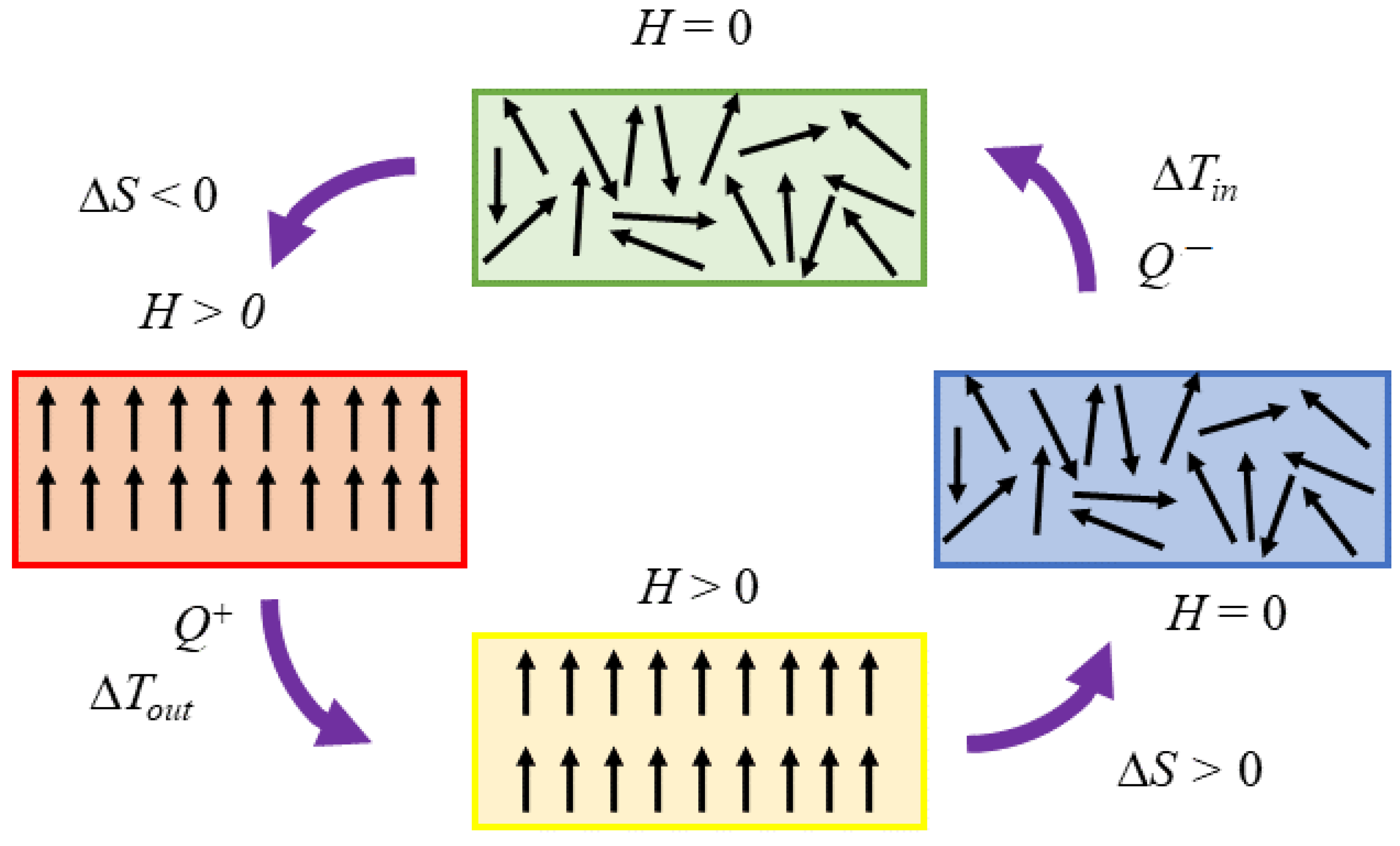
  • Magnetocaloric refrigeration: This is based on the magneto-thermodynamic phenomenon (magnetocaloric effect) that occurs in paramagnetic (and ferromagnetic) materials when an external magnetic field acts on them in adiabatic conditions [28]. This phenomenon occurs depending on the magnetic properties of the magnetocaloric materials. In particular, when a magnetic field is applied to these materials, they change their temperature due to the rearrangement of their magnetic momentum which, in turn, is related to an entropy variation that causes heat release. In paramagnetic materials, when the external field is switched off, their condition returns to the original state with the opposite effect.
Hence, thermal physicists and engineers are exploring new cooling technologies, among which magnetic refrigeration can provide very interesting results as one of the new emerging technologies. For this reason alone, in this study, magnetocaloric refrigeration is analysed, with a particular focus on the thermodynamic principles that drive this kind of technology. Moreover, when compared to conventional refrigeration and cooling systems, magnetic refrigeration is an environmentally friendly and efficient technology [29,30]; indeed, it has been highlighted as an environmentally friendly technology that has no direct ODP (ozone depletion potential) and zero direct GWP [31].
As previously pointed out, magnetic cooling technology uses the magnetocaloric effect (MCE) that occurs on some metallic alloys called magnetocaloric materials (MCMs). The technical basis is the reversible temperature change in paramagnetic salts for low-temperature changes due to adiabatic demagnetisation [1]. This technology is environmentally safe [32] for the following reasons [1,32]:
  • It does not involve refrigerants, such as CFCs, HCFCs, or ammonia, decreasing the related gas emissions.
  • It benefits from the intrinsic better performance of magnetocaloric materials.
  • It avoids ozone-depleting and greenhouse effects from direct emissions.

1.2. The Aim of This Study

This study aims to summarise the thermodynamic basis of the magnetic cycles for magnetocaloric refrigeration. This aspect is developed in Section 2, where the relations related to the thermodynamic approach are introduced, together with the main magnetocaloric thermodynamic cycles. Moreover, in order to provide an overview concerning the main challenges of magnetocaloric refrigeration, the main features and characteristics of the materials affected by magnetocaloric effects are presented in Section 3. In Section 4, an overview of the technological basis for magnetocaloric refrigerators is summarised. Finally, in Section 5, a brief discussion is provided, presenting some of the main challenges of these technologies (Section 6).

2. Fundamentals of Magnetic Cooling

2.1. Brief Historical Contextualisation

The first intuitions and observations on the magnetocaloric effect date back to 1843, when James Joule observed that iron samples subjected to repeated magnetisation/ demagnetisation cycles (induced with an electromagnetic field) led to a temperature variation due to the heat dissipated by induction currents [33]. Then, knowledge of some of the magnetic properties of ferromagnetic materials was uncovered (e.g., the loss of magnetic properties subsequent to heating above a certain temperature; this is now known as the Curie temperature). Thus, in 1860, starting from a thermodynamic approach, William Thomson (also known as Lord Kelvin) deduced the existence of a relation between the temperature dependence of the magnetisation of a body and its temperature response to an external magnetic field, revealing that these materials outflow heat when magnetised and absorb heat when demagnetised, and that the effect is amplified when closer to the loss of magnetisation temperature [33].
In 1881, Warburg showed the thermal effect of metal iron under interactions with varying magnetic fields and explained magnetic hysteresis. Then, with the works of Paul Langevin [34], Pierre Weiss, and Auguste Piccard [35], the discovery of the magnetocaloric effect was made, favouring the study of magnetic refrigeration. In particular, Weiss and Piccard found reversible heating in a nickel sample subjected to a 1.5 T magnetic field near its Curie temperature, with a 0.7 K temperature increase, also highlighting the reversibility of the effect and that the higher order of magnitude of the effect can allow it to be distinguished from the hysteresis effect. Then, the idea of exploiting this phenomenon to generate power or use it for refrigeration and heat pumping arose with Josef Stefan, Thomas Edison, and Nikola Tesla [33]. Afterwards, Debye and Giauque provided an explanation for the magnetocaloric effect, also obtaining the achievement of ultra-low temperatures under adiabatic demagnetisation cooling; its application for cryogenic refrigeration began in 1930, and in 1976, Brown achieved magnetic cooling at room temperature [36].

2.2. Thermodynamic Approach to Magnetic Refrigeration and Its Working Principle

In classical thermodynamics, the entropy concept is very useful, as it is a state function and, so, its variation results are independent of the pathway followed by the system during the transformation or the process [37]. The second law brings us to the Clausius inequality:
δ Q T 0 .
Entropy generation is introduced to avoid the difficulties concerning the inequalities [38] in designing and evaluations, even if nothing is really produced [37,38,39,40], obtaining the following relation [41]:
Δ S = δ Q T r e v = Δ S e + S g ,
where S g (which is called Δ S i r r elsewhere) is the entropy variation due to irreversibility [40], named entropy production (or generation), which represents a fundamental concept in modern thermal physics and engineering, as it is the quantity concerned with dissipative processes. In the last few decades, entropy generation has been shown to play a fundamental role in the analysis of real systems [37,40]. The quantity Δ S e is better defined as the entropy variation due to the reversible exchange of the same fluxes throughout the system boundaries. Thus, entropy results in a parameter characterising the thermodynamic state, while entropy generation measures how far the system is from the state that will be attained in a reversible manner [37,40,42]. In this context, the concept of random motion can be translated into the concept of order and disorder [40,42]; indeed, any energy exchange or conversion determines a change in the thermodynamic state of the system.
The magnetocaloric effect, which is intrinsically present in all magnetic materials, consists of the heat outflow from paramagnetic or soft ferromagnetic materials, with a related decrease in their magnetic entropy during the isothermal application of a magnetic field. On the contrary, if their magnetic entropy increases, a heat inflow occurs during an isothermal decrease of the magnetic field [32]. Thus, the results of the magnetocaloric effect are suitable for being exploited in a refrigeration cycle. A simplified scheme is reported in Figure 1, where it is possible to highlight that, once the magnetic field is applied ( H > 0 ), magnetic momentum alignment occurs with a related increase in the material’s temperature; then, heat outflow takes place ( Q + , Δ T o u t ), followed by the material being demagnetised ( H = 0 ), causing the magnetic moment disarrangement which, in turn, leads to a temperature drop ( Δ T i n ).
It is evident that, in a thermodynamic approach to magnetic materials, their total entropy S and the entropy of its magnetic subsystem S M (magnetic entropy) play fundamental roles. Indeed, as previously highlighted, any change in the applied magnetic field determines a variation in their entropy, with the consequence of causing temperature changes.
The entropy of a magnet, S T , H , can be evaluated as [43]
S T , H = S M T , H + S E T + S L T ,
where S M T , H is the magnetic entropy, which is magnetic field- and temperature-dependent; S L T is the lattice entropy, which is only temperature-dependent; and S E T is the electronic entropy, which is only temperature-dependent. Consequently, the entropy of a magnet is magnetic field- and temperature-dependent.
Now, we consider that the second law of thermodynamics can be written as
d S = 1 T d U + p d V μ 0 H T d M ,
where H is the intensity of the magnetic field, p is the pressure, V is the volume, μ 0 is the magnetic permeability of the vacuum, and M is the magnetic momentum. Considering that the volume remains constant during the magnetic interaction, the second law results in
d S = 1 T d U μ 0 H T d M .
Considering that the heat capacity at a constant pressure and magnetic field is
C H = U T H = δ Q T H = T S T p , H ,
it follows that
d S = C H T d T μ o H T d M .
Now, introducing an isoentropic transformation ( d S = 0 ), the temperature variation results are [44]
Δ T = H 1 H 2 μ 0 C H M T H d H ;
whereas, for an isothermal transformation, considering the Maxwell relation [45], we have
S H T = μ 0 M T H ,
which can be input into the constitutive equation in the thermodynamic space (H,T)
d S = S T H d T + S H T d H .
It follows that [45]
Δ S = H 1 H 2 μ 0 M T H d H .
From Equations (8) and (11), we can highlight the fundamental role of magnetisation variation in the magnetocaloric effect, and that this effect is large under the following conditions:
  • A large magnetic field variation;
  • Rapid changes in magnetisation with temperature;
  • A low specific heat.

2.3. Thermodynamic Cycles of Magnetocaloric Refrigeration

Magnetic refrigerators use magnetic materials to complete the cooling–refrigeration cycle. A magnetic refrigeration cycle involves magnetisation and demagnetisation processes, with heat outflow and inflow from the magnetic material, respectively, but there are also two more benign intermediate processes.
In cooling applications, the coefficient of performance ( C O P ) plays a fundamental role, as it expresses the efficiency of the cycle considered [43]; for magnetocaloric refrigeration, it is defined as usual:
C O P = Q 0 L ,
where Q 0 is the heat removed due to the magnetocaloric effect and L is the work carried out to sustain the reverse cycle. It can be highlighted that only magnetic entropy can be controlled by varying the magnitude of the magnetic field.
In the following sections, we discuss the thermodynamic approach being used and analyse the Ericsson and Brayton refrigeration cycles. The two cycles are represented in Figure 2.
(2a) 
Ericsson magnetic cooling cycle
The magnetic Ericsson cycle (Figure 2a) consists of two isothermal and two isofield processes:
1
Isothermal magnetisation process A B . The magnetic field increases from H 0 to H 1 , and heat is exchanged from a magnetic refrigerant to a regenerator fluid:
Q A B = T 1 ( S B S A ) ,
and the fluid increases in temperature.
2
Isofield cooling process B C . Heat is transferred from a magnetic refrigerant to a regenerator fluid:
Q B C = S C S B T d S .
3
Isothermal demagnetisation process C D . The magnetic field decreases from H 1 to H 0 , and the lower temperature regenerator fluid exchanges heat into the magnetic refrigerant:
Q C D = T 0 ( S D S C ) .
Afterwards, the temperature’s fluid decreases.
4
Field heating process C D . In the field of H 0 , the regenerator fluid absorbs heat:
Q B C = S A S D T d S .
Now, to evaluate the C O P , it is necessary to evaluate the previous entropy variations. In order to do so, we consider magnetisation M defined as
M = χ H + H e x t ,
where χ = C / ( T C λ ) is the magnetic susceptibility, with C being the Curie constant; T is the temperature; and λ = T C / C = 3 k T C | S | ( | S | + 1 ) μ 2 / ( N g 2 ) is a constant independent of temperature, with T C as the Curie temperature, k as the Boltzmann constant, S as the total spin, and g as the Landé factor defined as g = 1 + [ J ( J + 1 ) + | S | ( | S | + 1 ) | L | ( | L | + 1 ) ] / [ 2 | J | ( | J | + 1 ) ] , with J as the total angular momentum, L as the orbital momentum, N as the number of atoms or molecules, μ as the Bohr magneton, and H and H e x t as the internal and external magnetic fields, respectively. Therefore, the magnetisation results as:
M = C H + H e x t / ( T C λ ) .
Now, considering the Maxwell relations
S M H T = M T H = C H + H e x t T C λ 2 ,
and that [43]
M T H = C H + H e x t T C λ 2 ,
it follows that [43]
S M H T = C H + H e x t T Γ 2 ,
with
Γ = 12 C k T C μ 2 | S | | J | 2 ( | S | + 1 ) ( | J | + 1 ) 2 N 3 | J | ( | J | + 1 ) + | S | ( | S | + 1 ) | L | ( | L | + 1 ) 2 .
As a result, we can obtain the heat exchanged during the following:
  • Isothermal magnetisation process A B :
    Q A B = C T 1 ( T 1 Γ ) 2 ( H 1 H 0 ) .
  • Field heating process C D :
    Q C D = C T 0 ( T 0 Γ ) 2 ( H 1 H 0 ) .
From the previous considerations, we can evaluate the work as:
L = Q A B Q C D = C ( H 1 H 0 ) T 1 ( T 1 Γ ) 2 + T 0 ( T 0 Γ ) 2 ,
and the related coefficient of performance:
C O P = Q C D L = 1 T 1 T 0 T 0 Γ T 1 Γ 2 + 1 .
(2b) 
Brayton magnetic cooling cycle
In Figure 2b, the magnetic Brayton cycle is represented. It consists of two adiabatic and two isofield processes ( H 0 and H 1 ) that occur with high- and low-temperature heat sources T H and T C , respectively. It is composed as follows:
  • Isofield cooling process A B at a constant magnetic field of H 1 : A magnetic refrigerant outflows heat Q C D (or Q ), which is obtained by evaluating the area of the phase space between the isofield H 1 ( A B pathway) and the entropy axis
    Q C D = C D T d S .
  • Adiabatic demagnetisation B C process: No heat flow occurs.
  • Isofield heating process C D at a constant magnetic field H 0 : The magnetic refrigerant absorbs heat Q A B (or Q + ), which is obtained by evaluating the area of the phase space between the isofield H 0 ( C D pathway) and the entropy axis
    Q A B = B A T d S .
  • Adiabatic demagnetisation D A process: No heat flow occurs.
The magnetic refrigeration ideal, C O P , results are
C O P = Q C D L ,
where Q A B is the heat outflow due to the magnetocaloric effect and L is the work carried out.
During the isofield cooling process A B , at constant magnetic field H 1 , the magnetic refrigerant outflows heat Q A B equal to the area of the phase space between the isofield curve and the entropy axis; for the other isofield heating process C D at a constant magnetic field H 0 , a magnetic refrigerant absorbs heat Q C D equal to the area of phase space between the isoentropic H 0 and the entropy axis. No heat flow occurs during the adiabatic magnetisation process D A and the adiabatic demagnetisation B C process. Consequently, it follows that
Q A B = T 1 m ( S A S B ) ,
where T 1 m = ( T A + T B ) / 2 is the mean value of the temperature between T A and T B . Moreover, it follows that
Q C D = T 1 m ( S A S B ) ,
where T 0 m = ( T C + T D ) / 2 is the mean value of the temperature between T C and T D . Considering that ( S A S B ) = ( S D S C ) , then it follows that
L = Q 1 Q 0 = ( T 1 m T 0 m ) ( S A S B ) ,
and the coefficient of performance results in
C O P = Q C D L = T 0 m T 1 m T 0 m .

3. Magnetocaloric Materials

In order to develop cooling magnetocaloric devices, the main key elements are the magnetocaloric material itself, the coolants, and the regeneration materials. In this section, an overview of magnetocaloric materials for both solids and fluids is given. In general, to be suitable for refrigeration, the MCM should have the following properties:
  • A suitable Curie temperature for the considered application: The magnetocaloric effect has a larger magnitude at temperatures closer to its Curie temperature (the temperature at which the transition between ferromagnetic and paramagnetic phases occurs).
  • A suitable magnetocaloric effect intensity: This is mainly related to the adiabatic temperature variation and isothermal entropy variation. These, in turn, are related by means of the heat capacity of the material itself. For active magnetic refrigeration (AMR), the results are more relevant to a wide adiabatic temperature variation range and a smaller magnetic entropy variation due to the heat power transfer between the MCM and the heat-transfer medium. This is because the losses due to irreversibility can negatively affect a device’s performance when the adiabatic variation temperature is small.
  • A large magnetocaloric effect over a large temperature range.
  • A small hysteresis for first-order phase transition materials, as it implies energy losses.
  • A high thermal conductivity and thermal diffusivity to obtain a fast temperature response in material, favouring heat transfer to the refrigerant fluid.
  • A large material’s electrical resistivity minimises the generation of Foucault dissipative currents, which, in turn, causes a temperature increase in the material when the external magnetic field induction varies. This is particularly true when the operating frequencies are higher than 10 Hz [46].
  • Low corrosiveness, especially in relation to the heat transfer fluid: This effect can be inhibited by adding adequate substances to the fluid.
  • Easy to treat and manufacture: Suitable mechanical and processing properties are required within an optimal configuration for running the magnetocaloric device.

3.1. Solid Magnetic Materials

Considering the previous results of the thermodynamic analysis, we can highlight that only magnetic entropy S M ( T , H ) can be changed by changing the value of the magnetic field [32].
Concerning solid materials, the lattice entropy S L ( T ) presents a significant value at ambient temperature, with the consequence that the lattice itself requires a significant amount of cooling power to decrease its temperature in the adiabatic demagnetisation process [32]. Consequently, the choice of the magnetocaloric material is crucial when designing a magnetocaloric cooling system; indeed, the magnetocaloric effect requires materials with large total angular momentum numbers J and Landé factors g but with modest Debye and Curie temperatures in the range of working temperatures. Moreover, to reduce cooling power loss, their magnetic hysteresis must be quite null, and their electric resistance must be large. Concerning heat transfer, they must present low specific heat and high thermal conductivity.
The first material used at ambient temperature was 4f-lanthanide metal gadolinium (Gd), with a Curie temperature of 294 K [36]. It presents a second-order paramagnetic-to-ferromagnetic phase transition at the Curie temperature. Its adiabatic temperature changes are around 3 K for an applied magnetic field of 1 T, with a magnetocaloric effect of 2.6 K T−1. However, gadolinium can be easily corroded and oxidised. Some of the properties of gadolinium and other magnetocaloric materials are summarised in Table 1. Moreover, it should be highlighted that other works have also been developed to study the properties and fundamental quantities related to the magnetocaloric effect, for example, Gd 5 ( Si 1.8 Ge 2.2 ) in Ref. [47], Gd 5 ( Si x Ge 1 x ) 4 in Ref. [48], Gd 5 ( Si 1.5 Ge 2.5 ) in Ref. [49], R 5 ( Si x Ge 4 x ) in Ref. [50], and perovskite manganite compounds reviewed in Ref. [51]. Furthermore, perovskite manganese oxides and rare-earth transition metal compounds have recently been studied and shown to have large magnetic entropy variation [32], with a possible reduction in costs for cooling systems.

3.2. Ferrofluids

Ferrofluids are colloidal magnetic fluids (i.e., suspensions of magnetic nanoparticles in a liquid medium) that differ from other magnetic fluids for their size (3–15 nm) [76]. Their fundamental characteristic is that the magnetic particles maintain suspension without the following [77]:
  • Settling upon the gravitational field;
  • Segregating under a magnetic field gradient;
  • Agglomerating due to inter-particle interactions.
Indeed, to avoid any intermolecular interaction, ferrofluid particles are covered by a monolayer of surfactant [76].
In the absence of an external magnetic field, the magnetic moment associated with each particle is randomly oriented, with a related null magnetisation in ferrofluids. When an external constant magnetic field is applied, the magnetic moment associated with each particle aligns with a related magnetisation of the ferrofluid [76]. When a low-intensity magnetic field is applied, the magnetisation is proportional to a coupling coefficient, whereas in the presence of a high-intensity magnetic field, magnetisation saturates at a value proportional to the fraction of magnetic particles present in the ferrofluid itself [76].

3.3. Fundamentals of Ferro-Hydrodynamics

The fundamental approach to ferro-hydrodynamics is based on the following three balance equations:
  • The conservation of mass:
    ρ t + · ( ρ v ) = 0 ,
    where ρ is the density of the ferrofluid, v is its velocity of the ferrofluid flow, and t is the time, with a “ · ” divergence operator;
  • The balance of linear momentum:
    ( ρ v ) t + · ( ρ v v ) = · T + ρ f ,
    in which T = p I + T v + T a + T m is the stress tensor, where p I is the hydrostatic pressure, T v is the symmetric viscous stress tensors, T a is the antisymmetric viscous stress tensors, which is null if there is no exchange in angular momentum r × v , and T m is the magnetism of the fluid, and f is a body force per unit mass.
  • The balance of internal angular momentum:
    ( ρ s ) t + · ( ρ v s ) = · T + r × v + ρ f ,
    where s is the angular momentum (i.e., the rotation of a magnetic particle within a liquid medium).
When the ferrofluid interacts with an external magnetic field, B , magnetisation ( M ) occurs, which can be analytically described as the result of the action of the force f and the torque r × v . Considering a unit volume, the force results are ( M · ) B and the torque is M × B .
In the case of magnetic saturation, ferrofluids are able to preserve their colloidal nature, but the external magnetic field is able to change their viscosity to the physical condition in which nanoparticles do not follow the fluid’s deformation; that is, r × v 0 .

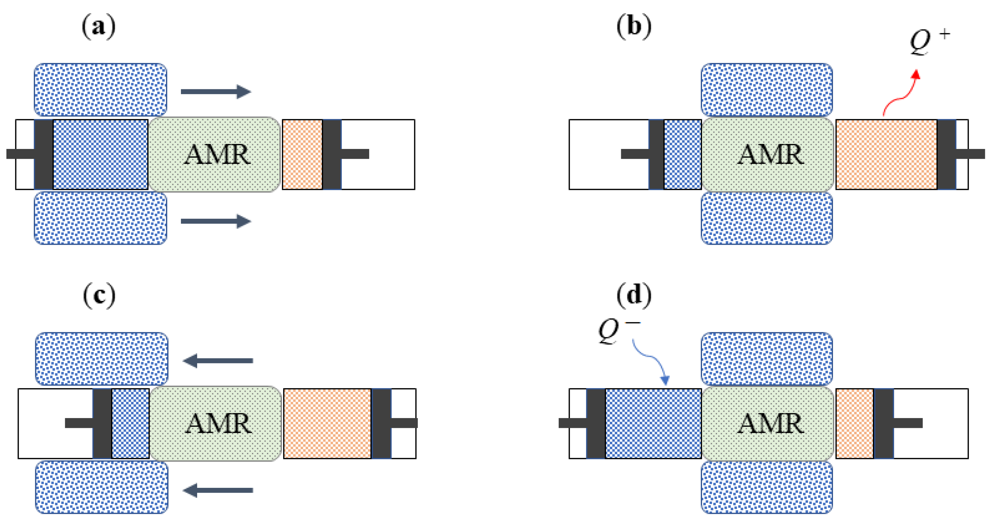
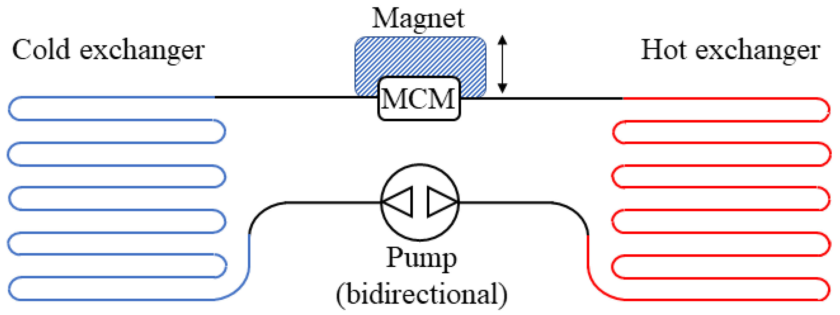
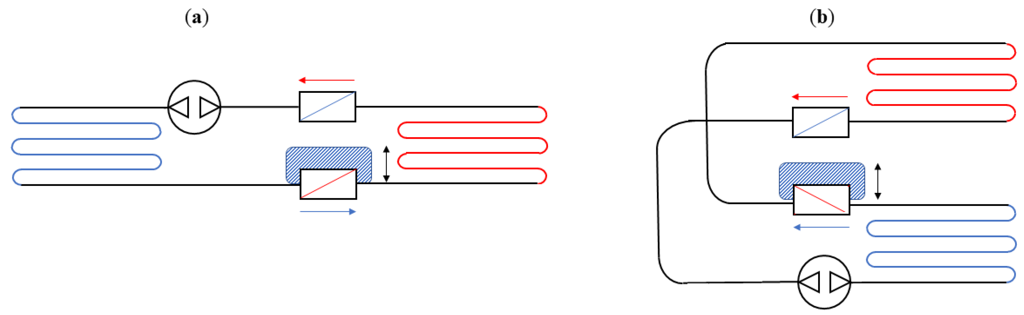
4. Technological Basis for Magnetocaloric Refrigerators

Magnetic refrigeration at room temperature [43] has recently attracted great interest, as it represents an environmentally safe cooling technology due to the use of new magnetocaloric alloys operating at ambient temperature (from 50   C to + 65   C) [1].
A fundamental aspect to be considered is that the magnetic cooling system is usually compact, as magnetic materials have a larger entropy density than the refrigerant gas versions [32]. Many prototypes using solid magnetic materials have been developed in the last 50 years. In this context, there are two broader families of prototypes: those that work under a reciprocating linear motion and those that work under a rotative motion. As previously pointed out, the magnetocaloric effect of a wide range of MCMs subjected to a constant magnetic field with magnetic induction values lower than 1.5 T usually corresponds to low adiabatic temperature variations (up to Δ T = 5 K) [56], which are too small to support the implementation of a cooling device, where approximately Δ T = 30 K is required. In order to overcome this technical issue, one of the most commonly adopted solutions is to dispose of the heat regenerator within the device itself. This element allows the system to indirectly exchange heat periodically through storing and transferring it in both senses using a regenerative (porous) material and an operative heat transfer fluid. A simplified representation of the working principle of this type of device is given in Figure 3. This kind of solution has already been presented by Brown [36] in the first prototype, which dates back to 1976.
In 1996, Zimm developed a magnetic refrigerator using around 3 kg of Gd as the working material and generated up to 500–600 W of cooling power in a 5 T magnetic field [78]. Moreover, since 2002, many prototypes have implemented magnetocaloric materials as permanent magnets that are able to generate high magnetic fields.
Furthermore, in the past few decades, many prototypes have been designed and realised using different structures, geometries, and movement systems. Their competitiveness with conventional refrigeration technologies can be compared based on their potential development, innovative systems, and economic and technological aspects, among which the most important influencing factors are represented by the design of a stable magnetic source and resistance, the development of new materials that can allow for an improvement in machine performance, and the optimisation of the arrangement and movement of system units.
A technical classification of AMR magnetocaloric refrigerator prototypes can be developed based on three main considerations:
  • The source type of the working MCM;
  • The arrangement of regenerators, with particular attention paid to both the magnetocaloric material (MCM) and the heat exchange carrier fluid;
  • The relative motion of the AMR concerning the magnetic field and the carrier fluid flow.
The first (single-effect) cooling machine using the magnetocaloric effect (Figure 4) includes three main components: the magnet, the magnetocaloric material, and the heat carrier fluid circuit. The four stages of the refrigeration cycle are obtained through the movement of the magnet, which can surround the magnetocaloric material and form the appropriate synchronisation of the passage of the fluid with the variation of the magnetic field. The alternating magnetisation phenomenon can be obtained using different methods (e.g., using permanent magnets or electromagnets), and the moving parts can be the magnet or the regenerator, or the system can have no moving parts at all, with a synchronised on/off switch for the magnetic field, depending on the fluid flow.
In order to obtain double the refrigeration capacity, it is possible to duplicate the single-effect device twice and join their hydraulic circuits, obtaining a double-effect device while maintaining the structure and the weight of the active magnetocaloric material as shown in Figure 5, where two equivalent systems (a) and (b) are shown. However, this can result in different systems, depending on the relative movement between the active magnetic material and the magnetic field, which can be performed through moving the magnet or the active material. These systems require adequate synchronisation, ensuring that when the largest magnetic field is applied to the active magnetocaloric material, its temperature distribution increases within the regenerator towards the hottest heat exchanger and, at the same time, the working fluid moves within the active magnetocaloric material towards the same hottest side of the circuit. When no magnetic field is applied to the active magnetocaloric material, its temperature distribution decreases within the regenerator towards the coldest heat exchanger and, at the same time, the working fluid moves within the active magnetocaloric material towards the coldest side of the circuit. Thus, when the magnet is moved from one active magnetocaloric material to the other, the flow is inverted. In particular, the (a) configuration has a parallel temperature distribution within the system, with an opposite direction to the working fluid flow; in the (b) configuration, only the fluid flow is parallel, which is in contrast to the temperature distributions on the active magnetocaloric materials.
Solution (a) of Figure 5 has been improved to obtain the evolutions represented in Figure 6. In particular, in configuration (1) (Figure 6), the bidirectional pump moves the working fluid into the heat exchangers with an alternating fluid flow. However, this kind of pump decreases the overall performance of the system due to the formation of dead volumes. In order to overcome this issue, it is possible to use three-way microvalves near the active magnetocaloric materials as shown in configuration (2) (Figure 6), which results in improved performance, even if it presents higher complexity in the hydraulic circuit.
However, oscillating the regenerators (Figure 6(1)) within the field linearly is not the only solution that can be implemented. Indeed, the rotational movement of the slider can also be performed as shown in Figure 7, where two different possible axes of rotation are highlighted. In Figure 7a, the bidirectional pump is substituted with a monodirectional pump, and a continuous rotating motion (counter-clockwise) occurs in relation to the direction of fluid flow. The cylinder can completely contain the magnetocaloric material (as described in Ref. [80]) or a ferrofluid suspension as highlighted in Ref. [81]. The system represented in Figure 7b can be used for both continuous or pulsed movement due to the fact that the rotation does not provide an inversion when turning the regenerators within the magnetocaloric material. If the pulsed mode is considered, when a half-turn is performed, the rotation may move backwards or forwards concerning its original position.
It should be highlighted that the technical development of magnetic refrigeration began with physical applications at low temperatures. The first generation of prototypes had the peculiarity of operating with superconducting magnets (therefore, they were constantly refrigerated with He for superfluid conditions) and low-frequency cycles; this hugely limited the achievement of significant efficiencies (the magnetic refrigeration systems range from 30 % to 60 % , compared to conventional compression refrigeration cycling, which ranges from 5 % to 10 % ). Some of the milestones achieved in the magnetocaloric refrigeration prototypes are summarised in the following paragraphs.
The first device, which was designed in 1976 by Brown [36], was a heat pump operating at room temperature using a superconducting magnet; it was refrigerated with liquid helium, with a magnetic field of 7 T. The temperature difference was of the order of 47 K with a 273 K thermal source and a 320 K heat exchanger; these operating conditions were achieved after 50 cycles of magnetisation/demagnetisation. The working fluid used for the heat exchange was water and 20 % ethyl alcohol. The low value of the device’s refrigeration power and efficiency was due to irreversible thermal losses.
In 1978, Steyert [80] introduced a system with active magnetocaloric material regenerators, where the magnetocaloric material had the double effect of exploiting the magnetocaloric effect and acting as a regenerator. In the subsequent years, some variants of this device were proposed by Barclay in 1982, Hakuraku and Hisanao in 1986, Kirol and Dacus in 1987, Hakuraku and Hideaki in 1988, and Peschka and Schneider in 1988 [82]. In 1997, the collaboration between AMES Laboratory and Astronautics Corporation of America led to a prototype based on a 0.15–0.30 mm diameter spherical Gd magnetocaloric material with superconducting magnet technology that worked for around 18 months, with a magnetic field of 5 T. The maximum cooling power obtained was 600 W, and the maximum coefficient of performance achieved was 60 % , with a temperature difference of approximately 38 K.
Since the early 2000s, a second generation of magnetocaloric effect refrigerators has been developed based on the presence of permanent magnets, rotary systems, and higher working frequencies; for example, Zimm et al. [78] built a prototype with a rotation disk in the MCM containing Nd 2 Fe 14 B spheres (average diameter of 0.25–0.50 mm), assembled using steel through a static magnetic field of 1.5 T. This device was made of a series of rotary valves, with the aim of injecting and distributing the carrier fluid (water with additional inhibitor) inside the hydraulic circuit to reduce the dead volumes. The operating frequencies ranged from 0.5 Hz to 4.0 Hz (noiseless device), achieving 50 W of cooling power with a temperature difference of 25 K. In 2002, a research group from Nanjing University in China [83] built a magnetocaloric system based on reciprocating motion, containing two permanent magnets placed in the Halbach arrangement, which allows for a 1.4 T magnetic field to be adapted to the construction needs. The magnetocaloric material was 0.2 mm diameter Gd spheres, powdered in Gd 5 Si 1.985 Ge 1.985 Ga 0.03 . The refrigerant fluid used was water, and the temperature difference achieved was 23 K. In 2005, in France, Cooltech Applications designed a system based on the rotary motor, which consists of eight supporting components made of a Gd-based synthetic material that is mechanically stable and thermally insulated. The rotary axes are made of stainless steel, where four NdFeB permanent magnets are rotated and generate a magnetic field in the range of 1.0–2.4 T. The optimisation of this device was obtained by using microchannel heat exchangers made up of 15 Gd plates with square geometry ( 45 × 45 mm) and a 0.2 mm gap for the carrier fluid. The flow rate of the refrigerant fluid was controlled to obtain a variable power between 100 W and 360 W.
In 2005, Xi’an Jiaotong University (China) created an experimental system that is able to operate at room temperature through the use of Gd and alloy Gd 5 Si 2 Ge 2 in an active magnetic regenerator mode [32,84]. The device was composed of a water-cooled electromagnet generating a maximum range of 2.18 T, a heat transfer system, and a mechanical subsystem for handling and controlling the data acquisition system operations. This device was tested under different operative conditions, varying the temperature range and fluid flow carrier, obtaining a maximum refrigeration power of 18.7 W using Gd particulates with 0.3 mm diameter. In the subsequent year, at the Chinese Academy of Sciences, an experimental device was designed [85] using He gas as the carrier fluid and two permanent magnets with cylindrical holes 40 mm in diameter, with a magnetic field of 1.5 T. The magnetocaloric material-regenerating medium was a porous medium made of Gd particles (with an average diameter of 1.4 mm) with a total mass equal to around 1.17 kg. The working frequency variation was between 0.4 Hz and 1 Hz, with a cooling power of 51.3 W and a temperature difference of 18.2 K.
At the University of Victoria (Canada), a permanent magnet refrigerator was designed to test various types and configurations of magnetocaloric refrigerants [52]. This system used a Halbach permanent magnet in NbFeB, obtaining a magnetic field span range of 0.10–1.47 T. It used a water carrier fluid with an outlet temperature from the hot side equal to 253–311 K and a variable frequency up to 4 Hz, obtaining a pressure difference of 0.15 bar at 0.5 Hz and 1 bar at 3 Hz. A comparable result was obtained at the University of Ljubljana in Slovenia [86] through designing a machine with a rotating cylinder (drum), achieving a magnetic field of 0.98 T, which was obtained by using four permanent magnets in NdFeB and low-C steel.
In Table 2, a summary of the main features of the prototypes realised in recent decades is provided. In particular, the information related to the year of announcement/publication, the type (Ro: rotating, Re: reciprocating), the maximum cooling power ( Q ˙ m a x ) or the maximum specific cooling power ( q ˙ m a x ) of the prototype, the magnetic field intensity ( Δ B ), the temperature variation obtained ( Δ T s p a n ), the MCM used, and some notes on the mass of the MCM/geometry and the frequency are given.

5. Discussion

Refrigeration has always been a very important and strategic sector for modern society. Indeed, in the early 1900s, the production of the first refrigeration compression devices was introduced for home use. Then, new refrigerants that were revolutionary for the time were introduced (e.g., CFCs—chlorofluorocarbons), improving the efficiency of refrigerators.
In recent years, the international scientific community has become more interested in magnetic refrigeration; therefore, it has become the subject of numerous research studies in the field of refrigeration and cooling technology. Indeed, magnetocaloric refrigeration represents a valid opportunity compared to traditional systems, representing an interesting alternative in the field of refrigeration as a consequence of the new regulations regarding the environmental impact of refrigerant fluids.
Green refrigeration systems based on the magnetocaloric effect are continuously receiving attention as sustainable methods to respond to the growing global energy demand [111,112,113]; indeed, they have been considered [29] to be potential substitutes for present-day commercialised gas compression technology due to their efficiency and environmental friendliness [51,114,115]. Moreover, their additional advantages include high stability, energy-saving ability, low noise, and no pollution [112].
A great number of prototypes have been designed based on different geometries and types of movement systems, as the factors that are able to influence the magnetocaloric effect can be addressed from the design of a stable magnetic source, meaning that the development of new materials can allow for improvements in device performance and the optimisation of the movement of system parts.
The fundamental basis for the technologies realised is based on the following kinds of devices:
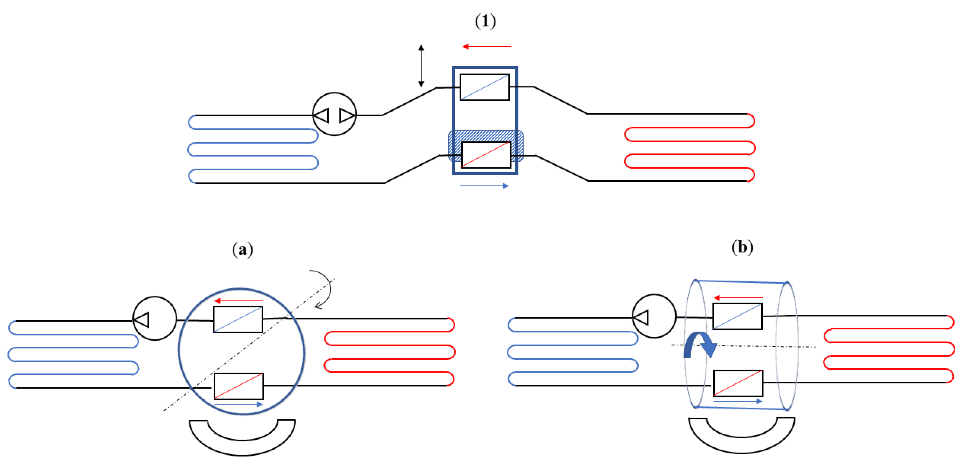
  • Reciprocating devices: These cooling systems are made up of three main components—a magnet, a magnetocaloric material, and a heat exchange carrier fluid. The four stages of the regenerative cycle are obtained through the movement of the magnet, which can surround the magnetocaloric material (or not) in relation to its position. Appropriate synchronisation of the passage of the thermal carrier fluid with the variation of the magnetic field is required.
  • Rotating devices: These systems are characterised by the alternating motion of the regenerators inside and outside of the magnetic field.
  • Ferrofluid magnetocaloric systems: These systems are receiving interest but, at present, the focus of research is centred on ferrofluid properties and production in order to reduce their costs and enable their use in simple industrial plants or home systems.
This review covers the thermodynamic approach to the magnetocaloric effect. Based on magnetocaloric cycles, the coefficient of performance is obtained through considering the entropy variation. Concerning the analytical results obtained, it is clear that the magnetocaloric effect depends on the magnetic properties of the material used. In particular, heat transfer is caused by entropy variation due to the interaction between the material and the magnetic field.
Furthermore, the efficiency of magnetic refrigeration [43] has been evaluated in the range of 30–60% for the Carnot cycle [78], and it must be compared with the efficiency of vapour compression refrigeration, which produces results on the order of 5–10% with respect to the Carnot cycle [32]. Moreover, we wish to highlight some considerations [32,43]:
  • When a constant magnetic field is applied to ferromagnets and paramagnets, the magnetisation decreases with temperature, ( M / T ) H < 0 .
  • The magnetocaloric effect strongly depends on both a large total angular momentum number J and the Landé factor g of the ferromagnetic material.
  • The magnetocaloric materials’ Debye temperature must be moderate.
  • A modest Curie temperature around the working temperature guarantees that the large magnetic entropy can change within the whole temperature range of the cycle.
  • Magnetocaloric materials must present a magnetic hysteresis as close as possible to zero.
  • A notable temperature variation and prompt heat exchange are guaranteed by a limited specific heat and a high thermal conductivity.
  • Eddy current losses can be avoided by broad electric resistance.
  • The coefficient of performance ( C O P ) is not affected by the value of the magnetic field but only by its variation. Moreover, the relation between C O P and temperature is non-linear.
  • At room temperature, the S L T quantity of Equation (3) results in values that are too wide to be neglected. Therefore, an amount of the refrigeration capacity of the MCM is used to cool the overall thermal load of the lattice system; this causes a decrease in the gross cooling capacity of the MCM [116]. Furthermore, as elucidated in Section 4, it is possible to improve the system’s coefficient of performance through restoring the heat expelled by the lattice into the lattice itself using a regenerator.

6. Conclusions and Future Challenges

Magnetocaloric refrigeration represents a promising alternative technology to conventional refrigeration, with possibly higher efficiencies while also addressing answers to sustainable refrigeration. However, a significant number of problems must be addressed. Indeed, the materials and heat transfer have been shown to possess limitations that must be carefully considered in any optimised design, as well as the pumps, drive motors, magnets, size, mass, and cost.
The efficiency of magnetocaloric devices is highly dependent upon adiabatic temperature change, so magnetic materials with the largest possible adiabatic temperature changes are needed. In relation to this, a reduction in the adiabatic temperature change—which is related to an appropriate design to satisfy the structural demands—cancels the magnetic forces from one part against another part of the cycle and decreases the smallest possible thermal mass through increasing the contact area with which to obtain the highest number of thermal transfers.
Concerning materials, researchers have studied first-order phase transition substances (e.g., La-Fe-Si and Mn-Fe-P-Ge) that exhibit better performance in the laboratory but lack some of the other characteristics required for applications in a device. Consequently, to date, Gd- and Gd-based alloys remain the principal materials for magnetocaloric use. Indeed, while mechanical stability, a decrease in thermal hysteresis, phase purity, and formability have been improved through developing new materials based on computer-guided techniques, composites, and additive manufacturing, their hysteresis, cyclability, and stability must still be significantly reduced. Moreover, the MCMs for the existing prototypes (highlighted in Section 4) are mostly packed beds of grain particles, even when a switch to parallel plates to obtain more periodic structures occurs. The maximum cooling power obtained by many prototypes is promising for household applications, considering that higher COP and Carnot efficiencies can be obtained by magnetocaloric refrigeration devices, when compared to traditional vapour compression refrigeration devices.
Concerning the prototype devices, one of the big issues that remains to be solved is the pressure drop that occurs in the heat carrier fluid, which affects the device’s performance. Nevertheless, overcoming this issue could lead to theoretical efficiency improvements on the order of 20–30%, compared to vapour compression cycles [117]. Thus, optimising the quality and heat transfer rate, together with minimisation of the pressure losses due to friction, should be the focus of future research, meaning that the carrier fluid will also play a fundamental role in the efficiency of these systems. Thus, special designs are required to generate wide temperature spans.
Concerning the market, the price for the magnetic refrigerant substances (La and Gd) is continuously constant due to their rare-earth nature and the by-products from Nd processing for the permanent magnet market. Indeed, the production of magnetic refrigerants on a large scale requires the development of production processes for regenerators without losing their magnetic properties.
Concerning ferrofluids, one of the principal problems is their small specific heat, with the consequence of high mass flows and high magnetic fields (above 3 T), the opposite of which is required in ambient temperature refrigeration, even if they present low flow friction.

Author Contributions

Conceptualisation, U.L. and G.G.; methodology, U.L. and G.G.; software, G.G.; validation, U.L. and G.G.; formal analysis, U.L.; investigation, U.L. and G.G.; resources, U.L.; data curation, G.G.; writing—original draft preparation, U.L. and G.G.; writing—review and editing, U.L. and G.G.; visualisation, G.G.; supervision, U.L.; project administration, U.L.; funding acquisition, U.L. All authors have read and agreed to the published version of the manuscript.

Funding

This research received no external funding.

Data Availability Statement

All the references for the data are quoted in the paper.

Conflicts of Interest

The authors declare no conflicts of interest.

Abbreviations

The following abbreviations are used in this manuscript:
AMRActive magnetic refrigeration
CFCChlorofluorocarbons
CO 2 Carbon dioxide
C O P Coefficient of performance
EUEuropean Union
GHGGreenhouse gas
GWPGlobal warming potential
HCFCHydrochlorofluorocarbons
HFCHydrofluorocarbons
MCEMagnetocaloric effect
MCMMagnetocaloric material
ODPOzone depletion potential

References

  1. Muller, C.; Vasile, C.; Risser, M.; Heitzler, J.C.; Keith, B. New air-conditioning and refrigeration magnetocaloric gas free system. In Proceedings of the 2010 International Symposium on Next-Generation Air Conditioning and Refrigeration Technology, Tokyo, Japan, 17–19 February 2010. [Google Scholar]
  2. Dupont, J.L. The Role of Refrigeration in the Global Economy. In Note (38th) on Refrigeration Technologies; IIF-IIR: Paris, France, 2019. [Google Scholar]
  3. Dong, Y.; Coleman, M.; Miller, S.A. Greenhouse Gas Emissions from Air Conditioning and Refrigeration Service Expansion in Developing Countries. Int. J. Refrig. 2021, 46, 59–83. [Google Scholar] [CrossRef]
  4. Foster, A.; Brown, T.; Evans, J. Carbon emissions from refrigeration used in the UK food industry. Int. J. Refrig. 2023, 150, 297–303. [Google Scholar] [CrossRef]
  5. Muller, C.; Vasile, C.; Risser, M.; Heitzler, J.C.; Keith, B. ASHRAE terminology. A Comprehensive Glossary of Terms for the Built Environment. 2024. Available online: https://terminology.ashrae.org/ (accessed on 1 June 2024).
  6. Vinoth Kanna, I.; Devaraj, A. Discussion of Past, Present and Future Perspectives of Refrigerants and Its Future Scope. In Innovative Design, Analysis and Development Practices in Aerospace and Automotive Engineering (I-DAD 2018); Chandrasekhar, U., Yang, L., Gowthaman, S., Eds.; Springer: Singapore, 2019; pp. 461–471. [Google Scholar] [CrossRef]
  7. McLinden, M.O.; Huber, M.L. (R)Evolution of Refrigerants. J. Chem. Eng. Data 2020, 65, 4176–4193. [Google Scholar] [CrossRef] [PubMed]
  8. EDGE Excellence in Design for Greater Efficiencies. Refrigerant Selection to Reduce Climate Impact Based on the Montreal Protocol; EDGE Guidance Document; International Finance Corporation (World Bank Group): Washington, DC, USA, 2017. [Google Scholar]
  9. Mota-Babiloni, A.; Makhnatch, P. Predictions of European refrigerants place on the market following F-gas regulation restrictions. Int. J. Refrig. 2021, 127, 101–110. [Google Scholar] [CrossRef]
  10. Ayub, Z.; Siller, D.A.; Gage, C.; Reindl, D.; Mueller, N.; DeBullet, J.; Pearson, A.; Ciconkov, R. ASHRAE Position Document on Natural Refrigerants; ASHRAE Position Document; American Society of Heating, Refrigerating and Air-Conditioning Engineers, Inc.: Atlanta, GA, USA, 2009. [Google Scholar]
  11. Wang, D.C.; Li, Y.H.; Li, D.; Xia, Y.; Zhang, J.P. A review on adsorption refrigeration technology and adsorption deterioration in physical adsorption systems. Renew. Sustain. Energy Rev. 2010, 14, 344–353. [Google Scholar] [CrossRef]
  12. Wang, R.Z.; Oliveira, R.G. Adsorption refrigeration—An efficient way to make good use of waste heat and solar energy. Prog. Energy Combust. Sci. 2006, 32, 424–458. [Google Scholar] [CrossRef]
  13. Deng, J.; Wang, R.Z.; Han, G.Y. A review of thermally activated cooling technologies for combined cooling, heating and power systems. Prog. Energy Combust. Sci. 2011, 37, 172–203. [Google Scholar] [CrossRef]
  14. Pons, M.; Kodama, A. Entropic analysis of adsorption open cycles for air conditioning. Part 1: First and second law analyses. Int. J. Energy Res. 2000, 24, 251–262. [Google Scholar] [CrossRef]
  15. Ahmadi, M.H.; Ahmadi, M.A.; Pourfayaz, F.; Bidi, M. Thermodynamic analysis and optimization for an irreversible heat pump working on reversed Brayton cycle. Energy Convers. Manag. 2016, 110, 260–267. [Google Scholar] [CrossRef]
  16. Giannetti, N.; Milazzo, A. Thermodynamic analysis of regenerated air-cycle refrigeration in high and low pressure configuration. Int. J. Refrig. 2014, 40, 97–110. [Google Scholar] [CrossRef]
  17. Shuailing, L.; Guoyuan, M.; Shuxue, X.; Yuexuan, G.; Xiaoya, J.; Guoqiang, W. A review of reverse Brayton air cycle refrigerators. Int. J. Refrig. 2023, 150, 200–214. [Google Scholar] [CrossRef]
  18. Dobre, C.; Grosu, L.; Dobrovicescu, A.; Chişiu, G.; Constantin, M. Stirling Refrigerating Machine Modeling Using Schmidt and Finite Physical Dimensions Thermodynamic Models: A Comparison with Experiments. Entropy 2021, 23, 368. [Google Scholar] [CrossRef] [PubMed]
  19. Mungan, C.E. Coefficient of performance of Stirling refrigerators. Eur. J. Phys. 2017, 38, 055101. [Google Scholar] [CrossRef]
  20. Getie, M.Z.; Lanzetta, F.; Bégot, S.; Admassu, B.T.; Hassen, A.A. Reversed regenerative Stirling cycle machine for refrigeration application: A review. Int. J. Refrig. 2020, 118, 173–187. [Google Scholar] [CrossRef]
  21. Salah, W.A.; Abuhelwa, M. Review of Thermoelectric Cooling Devices Recent Applications. J. Eng. Sci. Technol. 2020, 15, 455–476. [Google Scholar]
  22. Shilpa, M.K.; Raheman, A.; Aabid, A.; Baig, M.; Veeresha, R.K.; Kudva, N. A Systematic Review of Thermoelectric Peltier Devices: Applications and Limitations. Fluid Dyn. Mater. Process. 2023, 19, 187–206. [Google Scholar] [CrossRef]
  23. Baru, S.; Bhatia, S. A review on thermoelectric cooling technology and its applications. IOP Conf. Ser. Mater. Sci. Eng. 2020, 912, 042004. [Google Scholar] [CrossRef]
  24. Chen, L.; Lorenzini, G. Comparative performance for thermoelectric refrigerators with radiative and Newtonian heat transfer laws. Case Stud. Therm. Eng. 2022, 34, 102069. [Google Scholar] [CrossRef]
  25. Kutnjak, Z.; Rožič, B.; Pirc, R. Electrocaloric Effect: Theory, Measurements, and Applications. In Wiley Encyclopedia of Electrical and Electronics Engineering; John Wiley & Sons: Hoboken, NJ, USA, 2015; pp. 1–19. [Google Scholar] [CrossRef]
  26. Aprea, C.; Greco, A.; Maiorino, A.; Masselli, C. Electrocaloric refrigeration: An innovative, emerging, eco-friendly refrigeration technique. J. Phys. Conf. Ser. 2007, 796, 012019. [Google Scholar] [CrossRef]
  27. Ožbolt, M.; Kitanovski, A.; Tušek, J.; Poredoš, A. Electrocaloric refrigeration: Thermodynamics, state of the art and future perspectives. Int. J. Refrig. 2014, 40, 174–188. [Google Scholar] [CrossRef]
  28. Zarkevich, N.A.; Zverev, V.I. Viable Materials with a Giant Magnetocaloric Effect. Crystals 2020, 10, 815. [Google Scholar] [CrossRef]
  29. Alqahtani, A. Single Hidden Layer Intelligent Approach to Modeling Relative Cooling Power of Rare-Earth-Transition-Metal-Based Refrigerants for Sustainable Magnetic Refrigeration Application. Sustainability 2024, 16, 1542. [Google Scholar] [CrossRef]
  30. Brück, E. Developments in magnetocaloric refrigeration. J. Phys. D Appl. Phys. 2005, 38, 381–391. [Google Scholar] [CrossRef]
  31. Aprea, C.; Greco, A.; Maiorino, A.; Masselli, C. Magnetic refrigeration: An eco-friendly technology for the refrigeration at room temperature. J. Phys. Conf. Ser. 2015, 655, 012026. [Google Scholar] [CrossRef]
  32. Yu, B.; Gao, Q.; Zhang, B.; Meng, X.Z.; Chen, Z. Review on research of room temperature magnetic refrigeration. Int. J. Refrig. 2003, 26, 622–636. [Google Scholar] [CrossRef]
  33. Smith, A. Who discovered the magnetocaloric effect? Warburg, Weiss, and the connection between magnetism and heat. Eur. Phys. J. H 2013, 38, 507–517. [Google Scholar] [CrossRef]
  34. Langevin, P. Sur la théorie du magnétisme. J. Phys. Théor. Appl. 1905, 4, 678–693. [Google Scholar] [CrossRef]
  35. Weiss, P.; Piccard, A. Le phénomène magnétocalorique. J. Phys. Théor. Appl. 1917, 7, 103–109. [Google Scholar] [CrossRef]
  36. Brown, G.V. Magnetic heat pumping near room temperature. J. Appl. Phys. 1976, 47, 3673–3680. [Google Scholar] [CrossRef]
  37. Lucia, U. Mathematical consequences and Gyarmati’s principle in Rational Thermodynamics. Il Nuovo Cimento B 1995, B110, 1227–1235. [Google Scholar] [CrossRef]
  38. Grazzini, G.; Lucia, U. Global analysis of dissipations due to irreversibility. Rev. Génèrale Therm. 1997, 36, 605–609. [Google Scholar] [CrossRef]
  39. Lucia, U. Irreversibility and entropy in Rational Thermodynamics. Ric. Mat. 2001, L1, 77–87. [Google Scholar]
  40. Lucia, U. Probability, ergodicity, irreversibility and dynamical systems. Proc. R. Soc. A 2008, 464, 1089–1184. [Google Scholar] [CrossRef]
  41. Grazzini, G.; Lucia, U. Evolution rate of thermodynamic systems. In Proceedings of the 1st International Workshop Shape and Thermodynamics, Florence, Italy, 25–26 September 2008; CNR Solar: Lyon, France, 2008. [Google Scholar]
  42. Lucia, U. Irreversibility, entropy and incomplete information. Phys. A 2009, 388, 4025–4033. [Google Scholar] [CrossRef]
  43. Lucia, U. General approach to obtain the magnetic refrigeretion ideal Coefficient of Performance COP. Phys. A 2008, 387, 3477–3479. [Google Scholar] [CrossRef]
  44. de Oliveira, N.A.; von Ranke, P.J. Theoretical aspects of the magnetocaloric effect. Phys. Rep. 2010, 489, 89–159. [Google Scholar] [CrossRef]
  45. Gómez, J.R.; Garcia, R.F.; De Miguel Catoira, A.; Romero Gómez, M. Magnetocaloric effect: A review of the thermodynamic cycles in magnetic refrigeration. Renew. Sustain. Energy Rev. 2013, 17, 74–82. [Google Scholar] [CrossRef]
  46. Fiorillo, F. Characterization and Measurement of Magnetic Materials; Elsevier: Amsterdam, The Netherlands, 2004. [Google Scholar] [CrossRef]
  47. Morellon, L.; Algarabel, P.A.; Ibarra, M.R.; Blasco, J.; García-Landa, B.; Arnold, Z.; Albertini, F. Magnetic-field-induced structural phase transition in Gd5(Si1.8Ge2.2). Phys. Rev. B 1998, 58, R14721–R14724. [Google Scholar] [CrossRef]
  48. Morellon, L.; Blasco, J.; Algarabel, P.A.; Ibarra, M.R. Nature of the first-order antiferromagnetic-ferromagnetic transition in the Ge-rich magnetocaloric compounds Gd5(SixGe1-x)4. Phys. Rev. B 2000, 62, 1022–1026. [Google Scholar] [CrossRef]
  49. Levin, E.M.; Gschneidner, K.A., Jr.; Pecharsky, V.K. Magnetic properties of Gd5(Si1.5Ge2.5) near the temperature and magnetic field induced first order phase transition. J. Magn. Magn. Mater. 2001, 231, 235–245. [Google Scholar] [CrossRef]
  50. Pecharsky, A.O.; VK, V.K.P.; Gschneidner, K.A., Jr. Uncovering the structure–property relationships in R5(SixGe4-x) intermetallic phases. J. Alloys Compd. 2002, 344, 362–368. [Google Scholar] [CrossRef]
  51. Ayas, A.O.; Çetin, S.K.; Akça, G.; Akyol, M.; Ekicibil, A. Magnetic refrigeration: Current progress in magnetocaloric properties of perovskite manganite materials. Mater. Today Commun. 2023, 35, 105988. [Google Scholar] [CrossRef]
  52. Bjørk, R.; Bahl, C.R.H.; Smith, A.; Pryds, N. Review and comparison of magnet designs for magnetic refrigeration. Int. J. Refrig. 2010, 33, 437–448. [Google Scholar] [CrossRef]
  53. Dan’kov, S.Y.; Tishin, A.M.; Pecharsky, V.K.; Gschneidner, K.A. Magnetic phase transitions and the magnetothermal properties of gadolinium. Phys. Rev. B 1998, 57, 3478–3490. [Google Scholar] [CrossRef]
  54. Pecharsky, V.K.; Gschneidner, K.A., Jr. Giant magnetocaloric effect in Gd5(Si2Ge2). Phys. Rev. Lett. 1997, 78, 4494–4497. [Google Scholar] [CrossRef]
  55. Spichkin, Y.I.; Pecharsky, V.K.; Gschneidner, K.A. Preparation, crystal structure, magnetic and magnetothermal properties of (GdxR5-x)Si4, where R=Pr and Tb, alloys. J. Appl. Phys. 2001, 89, 1738–1745. [Google Scholar] [CrossRef]
  56. Gschneidner, K.A.; Pecharsky, V.K. Magnetocaloric Materials. Annu. Rev. Mater. Sci. 2000, 30, 387–429. [Google Scholar] [CrossRef]
  57. Misra, S.; Mozharivskyj, Y.; Tsokol, A.O.; Schlagel, D.L.; Lograsso, T.A.; Miller, G.J. Structural, magnetic, and thermal characteristics of the phase transitions in Gd5GaxGe4-x magnetocaloric materials. J. Solid State Chem. 2009, 182, 3031–3040. [Google Scholar] [CrossRef]
  58. Dai, W.; Shen, B.; Li, D.; Gao, Z. New magnetic refrigeration materials for temperature range from 165 K to 235 K. J. Alloys Compd. 2000, 311, 22–25. [Google Scholar] [CrossRef]
  59. Gschneidner, K.A.; Pecharsky, V.K. The influence of magnetic field on the thermal properties of solids. Mater. Sci. Eng. A 2000, 287, 301–310. [Google Scholar] [CrossRef]
  60. Canepa, F.; Cirafici, S.; Napoletano, M.; Merlo, F. Magnetocaloric properties of Gd7Pd3 and related intermetallic compounds. IEEE Trans. Magn. 2002, 38, 3249–3251. [Google Scholar] [CrossRef]
  61. Pecharsky, V.K.; Gschneidner, K.A., Jr. Tunable magnetic regenerator alloys with a giant magnetocaloric effect for magnetic refrigeration from ∼20 to ∼290 K. Appl. Phys. Lett. 1997, 70, 3299–3301. [Google Scholar] [CrossRef]
  62. Pecharsky, V.K.; Gschneidner, K.A., Jr. Effect of alloying on the giant magnetocaloric effect of Gd5(Si2Ge2). J. Magn. Magn. Mater. 1997, 167, 179–184. [Google Scholar] [CrossRef]
  63. Pecharsky, V.K.; Gschneidner, K.A., Jr. Phase relationships and crystallography in the pseudobinary system Gd5Si4-Gd5Ge4. J. Alloys Compd. 1997, 260, 98–106. [Google Scholar] [CrossRef]
  64. Giguère, A.; Földeàki, M.; Gopal, B.R.; Chahine, R.; Bose, T.K. Direct measurement of the ‘Giant’ adiabatic temperature change in Gd5Si2Ge2. Phys. Rev. Lett. 1999, 83, 2262–2265. [Google Scholar] [CrossRef]
  65. Pecharsky, V.K.; Gschneidner, K.A., Jr.; Pecharsky, V.K.; Schindler, C.E. The room temperature metastable/stable phase relationships in the pseudo-binary Gd5Si4–Gd5Ge4 system. J. Alloys Compd. 2002, 338, 126–135. [Google Scholar] [CrossRef]
  66. Pecharsky, V.K.; Gschneidner, K.A., Jr. The giant magnetocaloric effect in Gd5(SixGe1-x) materials for magnetic refrigeration. Adv. Cryog. Eng. 1998, 43, 1729–1736. [Google Scholar] [CrossRef]
  67. Gschneidner, K.A., Jr.; Pecharsky, V.K.; Pecharsky, A.O.; Ivtchenko, V.V.; Levin, E.M. The nonpareil R5(SixGe1-x)4 phases. Phys. Rev. Lett. 2000, 303–304, 214–222. [Google Scholar] [CrossRef]
  68. Hu, F.-x.; Shen, B.-g.; Sun, J.-r.; Wu, G.-h. Large magnetic entropy change in a Heusler alloy Ni52.6Mn23.1Ga24.3 single crystal. Phys. Rev. B 2001, 64, 132412. [Google Scholar] [CrossRef]
  69. Wada, H.; Tanabe, Y. Giant magnetocaloric effect of MnAs1-x Sbx. Appl. Phys. Lett. 2001, 79, 3302–3304. [Google Scholar] [CrossRef]
  70. Wada, H.; Taniguchi, K.; Tanabe, Y. Extremely Large Magnetic Entropy Change of MnAs1-xSbx near Room Temperature. Mater. Trans. 2002, 43, 73–77. [Google Scholar] [CrossRef]
  71. Wada, H.; Morikawa, T.; Taniguchi, K.; Shibata, T.; Yamada, Y.; Akishige, Y. Giant magnetocaloric effect of MnAs1-xSbx in the vicinity of first-order magnetic transition. Phys. B Condens. Matter 2003, 328, 114–116. [Google Scholar] [CrossRef]
  72. Tegus, O.; Brück, E.; Buschow, K.H.J.; de Boer, F.R. Transition-metal-based magnetic refrigerants for room-temperature applications. Nature 2002, 415, 150–152. [Google Scholar] [CrossRef] [PubMed]
  73. Tan, X.; Chai, P.; Thompson, C.M.; Shatruk, M. Magnetocaloric Effect in AlFe2B2: Toward Magnetic Refrigerants from Earth-Abundant Elements. J. Am. Chem. Soc. 2013, 135, 9553–9557. [Google Scholar] [CrossRef] [PubMed]
  74. Fujita, A.; Fujieda, S.; Hasegawa, Y.; Fukamichi, K. Itinerantelectron metamagnetic transition and large magnetocaloric effects in La(FexSi1-x)13 compounds and their hydrides. Phys. Rev. B 2003, 67, 104416. [Google Scholar] [CrossRef]
  75. Hu, F.x.; Shen, B.g.; Sun, J.r.; Wang, G.j.; Cheng, Z.h. Very large magnetic entropy change near room temperature in LaFe11.2Co0.7Si1.1. Appl. Phys. Lett. 2002, 80, 826–828. [Google Scholar] [CrossRef]
  76. Rosensweig, R.E. Ferrohydrodynamics; Cambridge University Press: Cambridge, UK, 1985. [Google Scholar]
  77. Nkurikiyimfura, I.; Wang, Y.; Pan, Z. Heat transfer enhancement by magnetic nanofluids—A review. Renew. Sustain. Energy Rev. 2013, 21, 548–561. [Google Scholar] [CrossRef]
  78. Zimm, C.; Jastrab, A.; Sternberg, A.; Pecharsky, V.K.; Gschneidner, K.A., Jr.; Osborne, M.; Anderson, I. Description and performance of near-room temperature magnetic refrigerator. In Advances in Cryogenic Engineering; Kittel, P., Ed.; Springer: Berlin/Heidelberg, Germany, 1998; Volume 43, pp. 1759–1766. [Google Scholar] [CrossRef]
  79. Scarpa, F.; Tagliafico, G.; Tagliafico, L. Classification proposal for room temperature magnetic refrigerators. Int. J. Refrig. 2012, 35, 453–458. [Google Scholar] [CrossRef]
  80. Steyert, W.A. Stirling-cycle rotating magnetic refrigerators and heat engines for use near room temperature. J. Appl. Phys. 1978, 49, 1216–1226. [Google Scholar] [CrossRef]
  81. Rosensweig, R. Refrigeration aspects of magnetic particle suspensions. Int. J. Refrig. 2006, 29, 1250–1258. [Google Scholar] [CrossRef]
  82. Kamran, M.S.; Ahmad, H.O.; Wang, H.S. Review on the developments of active magnetic regenerator refrigerators–Evaluated by performance. Renew. Sustain. Energy Rev. 2020, 133, 110247. [Google Scholar] [CrossRef]
  83. Lu, D.W.; Wu, X.N.; Wu, H.B.; Jin, X. A permanent magnet magnetorefrigerator study using Gd/GdeSiGe/GdeSiGeeGa alloys. In Proceedings of the First International Conference on Magnetic Refrigeration of Room Temperature, Montreux, Switzerland, 27–30 September 2005; pp. 206–291. [Google Scholar]
  84. Gao, Q.; Yu, B.F.; Wang, C.F.; Zhang, B.; Yang, D.; Zhang, Y. Experimental investigation on refrigeration performance of a reciprocating active magnetic regenerator of room temperature magnetic refrigeration. Int. J. Refrig. 2006, 29, 1274–1285. [Google Scholar] [CrossRef]
  85. Yao, G.H.; Gong, M.Q.; Wu, J.F. Experimental study on the performance of a room temperature magnetic refrigerator using permanent magnets. Int. J. Refrig. 2013, 29, 1267–1273. [Google Scholar] [CrossRef]
  86. Tušek, J.; Zupan, S.; Šarlah, A.; Prebil, I.; Poredoš, A. Development of a rotary magnetic refrigerator. Int. J. Refrig. 2010, 33, 294–300. [Google Scholar] [CrossRef]
  87. Kirol, L.D.; Dacus, M.W. Rotary Recuperative Magnetic Heat Pump. In Advances in Cryogenic Engineering; Springer: Boston, MA, USA, 1988; pp. 757–765. [Google Scholar] [CrossRef]
  88. Rowe, A.; Tura, A. Experimental investigation of a three-material layered active magnetic regenerator. Int. J. Refrig. 2006, 29, 1286–1293. [Google Scholar] [CrossRef]
  89. Bingfeng, Y.; Yan, Z.; Qiang, G.; Dexi, Y. Research on performance of regenerative room temperature magnetic refrigeration cycle. Int. J. Refrig. 2006, 29, 1348–1357. [Google Scholar] [CrossRef]
  90. Okamura, T.; Yamada, K.; Hirano, N.; Nagaya, S. Performance of a room-temperature rotary magnetic refrigerator. Int. J. Refrig. 2006, 29, 1327–1331. [Google Scholar] [CrossRef]
  91. Zimm, C.; Boeder, A.; Chell, J.; Sternberg, A.; Fujita, A.; Fujieda, S.; Fukamichi, K. Design and performance of a permanent-magnet rotary refrigerator. Int. J. Refrig. 2006, 29, 1302–1306. [Google Scholar] [CrossRef]
  92. Huang, J.; Liu, J.; Jin, P.; Yan, H.; Qiu, J.; Xu, L.; Zhang, J. Development of permanent magnetic refrigerator at room temperature. Rare Met. 2006, 25, 641–644. [Google Scholar] [CrossRef]
  93. Zimm, C.; Auringer, J.; Boeder, A.; Chell, J.; Russek, S.; Sternberg, A. Design and initial performance of a magnetic refrigerator with a rotating permanent magnet. In Proceedings of the 2nd International Conference on Magnetic Refrigeration at Room Temperature, Portoroz, Slovenia, 11–13 April 2007; Volume 2, pp. 341–347. [Google Scholar]
  94. Tura, A.; Rowe, A. Permanent magnet magnetic refrigerator design and experimental characterization. Int. J. Refrig. 2011, 34, 628–639. [Google Scholar] [CrossRef]
  95. Hirano, N.; Miyazaki, Y.; Bae, S.; Takata, H.; Kawanami, T.; Xiao, F.; Okamura, T.; Wada, H. Development of room temperature magnetic heat pump technologies as a national project in Japan. In Proceedings of the 6th IIR/IIF International Conference on Magnetic Refrigeration at Room Temperature, THERMAG 2014, Victoria, BC, Canada, 7–10 September 2014; Rowe, A., Ed.; International Institute of Refrigeration: Paris, France, 2011. Refrigeration Science and Technology. pp. 115–116. [Google Scholar]
  96. Engelbrecht, K.; Eriksen, D.; Bahl, C.; Bjørk, R.; Geyti, J.; Lozano, J.; Nielsen, K.; Saxild, F.; Smith, A.; Pryds, N. Experimental results for a novel rotary active magnetic regenerator. Int. J. Refrig. 2012, 35, 1498–1505. [Google Scholar] [CrossRef]
  97. Benedict, M.; Sherif, S.; Schroeder, M.; Beers, D. Experimental impact of magnet and regenerator design on the refrigeration performance of first-order magnetocaloric materials. Int. J. Refrig. 2017, 74, 190–199. [Google Scholar] [CrossRef]
  98. Tagliafico, L.A.; Scarpa, F.; Valsuani, F.; Tagliafico, G. Preliminary experimental results from a linear reciprocating magnetic refrigerator prototype. Appl. Therm. Eng. 2013, 52, 492–497. [Google Scholar] [CrossRef]
  99. Jacobs, S.; Auringer, J.; Boeder, A.; Chell, J.; Komorowski, L.; Leonard, J.; Russek, S.; Zimm, C. The performance of a large-scale rotary magnetic refrigerator. Int. J. Refrig. 2014, 37, 84–91. [Google Scholar] [CrossRef]
  100. Arnold, D.; Tura, A.; Ruebsaat-Trott, A.; Rowe, A. Design improvements of a permanent magnet active magnetic refrigerator. Int. J. Refrig. 2014, 37, 99–105. [Google Scholar] [CrossRef]
  101. Bahl, C.; Engelbrecht, K.; Eriksen, D.; Lozano, J.; Bjørk, R.; Geyti, J.; Nielsen, K.; Smith, A.; Pryds, N. Development and experimental results from a 1 kW prototype AMR. Int. J. Refrig. 2014, 37, 78–83. [Google Scholar] [CrossRef]
  102. Velázquez, D.; Estepa, C.; Palacios, E.; Burriel, R. A comprehensive study of a versatile magnetic refrigeration demonstrator. Int. J. Refrig. 2016, 63, 14–24. [Google Scholar] [CrossRef]
  103. Lozano, J.A.; Capovilla, M.S.; Trevizoli, P.V.; Engelbrecht, K.; Bahl, C.R.; Barbosa, J.R. Development of a novel rotary magnetic refrigerator. Int. J. Refrig. 2016, 68, 187–197. [Google Scholar] [CrossRef]
  104. Trevizoli, P.V.; Nakashima, A.T.; Peixer, G.F.; Barbosa, J.R. Performance evaluation of an active magnetic regenerator for cooling applications-part I: Experimental analysis and thermodynamic performance. Int. J. Refrig. 2016, 72, 192–205. [Google Scholar] [CrossRef]
  105. Huang, B.; Zeng, D.; Brük, E. Magnetic heating air-conditioning & refrigeration (HACR) prototype for experimental purpose. In Proceedings of the 8th IIR/IIF International Conference on Caloric Cooling, Darmstadt, Germany, 16–20 September 2018; Ihnfeldt, R.V., Jin, S., Chen, R., Chun, R., Eds.; International Institute of Refrigeration: Paris, France, 2018. Refrigeration Science and Technology. pp. 115–116. [Google Scholar]
  106. Baser, O.; Akbostanci, M.; Elerman, Y.; Dincer, I. Experimental investigation of a rotary magnetic refrigerator. In Proceedings of the 8th IIR/IIF International Conference on Caloric Cooling, Darmstadt, Germany, 16–20 September 2018; Ihnfeldt, R.V., Jin, S., Chen, R., Chun, R., Eds.; International Institute of Refrigeration: Paris, France, 2018. Refrigeration Science and Technology. pp. 115–116. [Google Scholar]
  107. Lionte, S.; Barcza, A.; Hittinger, M.; Risser, M.; Muller, C.; Katter, M. Recent experimental results of first order LaFeSi-based magnetocaloric materials in an active magnetic regeneration device. In Proceedings of the 8th IIR/IIF International Conference on Caloric Cooling, Darmstadt, Germany, 16–20 September 2018; Ihnfeldt, R.V., Jin, S., Chen, R., Chun, R., Eds.; International Institute of Refrigeration: Paris, France, 2018. Refrigeration Science and Technology. pp. 56–61. [Google Scholar]
  108. Lionte, S.; Risser, M.; Muller, C. A 15 kW magnetocaloric proof-of-concept unit: Initial development and first experimental results. Int. J. Refrig. 2021, 122, 256–265. [Google Scholar] [CrossRef]
  109. Nakashima, A.T.; Fortkamp, F.P.; de Sá, N.M.; dos Santos, V.M.; Hoffmann, G.; Peixer, G.F.; Dutra, S.L.; Ribeiro, M.C.; Lozano, J.A.; Barbosa, J.R. A magnetic wine cooler prototype. Int. J. Refrig. 2021, 122, 110–121. [Google Scholar] [CrossRef]
  110. Peixer, G.F.; Silva, M.C.; Lorenzoni, A.; Hoffmann, G.; dos Santos, D.; do Rosário, G.M.; Pagnan, E.; Teza, H.F.; Silva, P.M.; Dutra, S.L.; et al. A magnetocaloric air-conditioning system prototype. Int. J. Refrig. 2023, 151, 1–13. [Google Scholar] [CrossRef]
  111. Xiao, G.; He, W.; Chen, P.; Wu, X. Effect of Nd-substitution on the structural, magnetic and magnetocaloric properties of La0.67-xNdxCa0.13Ba0.2MnO3 manganites. Phys. B Condens. Matter 2019, 564, 133–142. [Google Scholar] [CrossRef]
  112. Bahhar, S.; Lemziouka, H.; Boutahar, A.; Bioud, H.; Lassri, H.; Hlil, E.K. Influence of La3+ site substitution on the structural, magnetic and magnetocaloric properties of ZnFe2-xLaxO4 (x = 0.00, 0.001, 0.005 and 0.01) spinel zinc ferrites. Chem. Phys. Lett. 2019, 716, 186–191. [Google Scholar] [CrossRef]
  113. Xie, H.; Su, W.; Lu, H.; Mo, Z.; Wang, D.; Sun, H.; Tian, L.; Gao, X.; Li, Z.; Shen, J. Enhanced low-field magnetocaloric effect in Nb and Al co-substituted EuTiO3 compounds. J. Mater. Sci. Technol. 2022, 118, 128–135. [Google Scholar] [CrossRef]
  114. Ayadi, F.; Ammar, S.; Nowak, S.; Cheikhrouhou-Koubaa, W.; Regaieg, Y.; Koubaa, M.; Monnier, J.; Sicard, L. Importance of the synthesis and sintering methods on the properties of manganite ceramics: The example of La0.7Ca0.3MnO3. J. Alloys Compd. 2018, 759, 52–59. [Google Scholar] [CrossRef]
  115. Wang, G.F.; Zhao, Z.R.; Li, L.R.; Zhang, X.F. Effect of non-stoichiometry on the structural, magnetic and magnetocaloric properties of La0.67Ca0.33Mn1+δO3 manganites. J. Magn. Magn. Mater. 2016, 397, 198–204. [Google Scholar] [CrossRef]
  116. Chang, S.N.; Yan, X.G. Thermodyncamic norm for selecting refrigerant of magnetic refrigeration near room temperature. J. Beijing Univ. Aeronaut. Astronaut. 1997, 23, 639–642. [Google Scholar]
  117. Russek, S.L.; Zimm, C.B. Potential for cost effective magnetocaloric air conditioning systems. Int. J. Refrig. 2006, 29, 1366–1373. [Google Scholar] [CrossRef]
Figure 1. A simplified scheme of a magnetic refrigeration cycle, considering adiabatic conditions.
Energies 17 03585 g001
Figure 2. Temperature vs entropy, Ericsson (a) and Brayton (b) magnetic cycles.
Energies 17 03585 g002
Figure 3. Working principle scheme of a linear AMR evolving with a Brayton-like thermodynamic cycle, where the magnet is displaced linearly (movement indicated with arrows). In phase (a) the magnetisation occurs. In (b) the heat is rejected to the hot sink, while the (c) phase represents demagnetisation, which is followed by (d), where the useful effect occurs.
Energies 17 03585 g003
Figure 4. Simplified scheme of a single-effect device with linear motion for the permanent magnet in relation to the active magnetocaloric material (MCM) as described in Ref. [79].
Energies 17 03585 g004
Figure 5. Simplified scheme of a double-effect device (described in [79]) with a moving magnet. The bidirectional pumps are able to provide the alternate carrier fluid flow; in order to work properly, the bidirectional flow has to be synchronised.
Energies 17 03585 g005
Figure 6. Simplified scheme for moving the active magnetocaloric material device as described in [79]. Configuration (1) presents a bidirectional pump and the linear motion of the active magnetocaloric material (two beds within a moving slider), where the magnet has a fixed position. Configuration (2) presents a unidirectional pump with three-way microvalves with the aim of improving the efficiency of the system. The external grey pipes contain dead fluid.
Energies 17 03585 g006
Figure 7. According to the configuration of a moving active material (Figure 6), it is possible to evolve towards two different rotating systems, with the first being a continuous motion (a) and the other being a continuous or discontinuous rotation along the axis parallel to the fluid flow circuit (b).
Energies 17 03585 g007
Table 1. Some of the properties of gadolinium and other magnetocaloric materials and compounds.
CurieMagnetic FieldSpecific Magnetic
MaterialTemperatureVariationEntropy VariationRefs.
[K][T][J kg 1 K 1 ]
1.03.1[52]
1.53.8[53]
2.05[54]
Gd2943.07.1[53]
5.010.2[53]
6.011.4[53]
Gd 5 Si 4 3465.08.2[55]
Gd 5 Si 3 Ge3235.08.7[56]
Gd 5 Si 2.5 Ge 1.5 3135.09.4[56]
Gd 5 Ga 0.7 Ge 3 1752.06.0[57]
5.013.6[57]
Gd 0.5 Dy 0.5 2305.010.2[58]
Gd 0.74 Tb 0.26 2805.011.5[59]
Gd 7 Pd 3 3235.08.5[60]
Gd 5 ( Si 0.43 Ge 0.57 ) 4 2475.039.0[61]
Gd 5 ( Si 0.5 Ge 0.5 ) 4 2762.027.0[62,63]
Gd 5 ( Si 0.5 Ge 0.5 ) 4 5.018.4[61,64]
Gd 5 ( Si 0.505 Ge 495 ) 4 2805.011.7[65]
Gd 5 ( Si 1.985 Ge 1.985 Ga 0.03 ) 2 2905.015.0[66]
Dy 5 Si 3.5 Ge 0.5 1305.09.5[67]
Dy 5 Si 3 Ge655.034.0[67]
Ni 52.6 Mn 23.1 Ga 24.3 3005.018.0[68]
MnAs3185.030.0[69]
MnAs 0.9 Sb 0.1 2865.030.0[70]
MnAs 0.95 Sb 0.05 3092.027.0[69]
5.031.0[69]
MnAs 0.85 Sb 0.15 2605.026.0[71]
MnAs 0.25 Sb 0.25 2332.018.0[71]
5.024.0[71]
MnFeP 0.45 As 0.55 3005.018.0[72]
AlFe 2 B 2 2825.07.3[73]
LaFe 11.44 Si 1.56 1952.020.0[74]
5.023.0[74]
LaFe 11.57 Si 1.43 1882.024.0[74]
5.026.0[74]
LaFe 11.2 Co 0.7 Si 1.1 2742.012.0[75]
5.020.0[75]
Table 2. Information related to some of the prototypes available in the literature from recent decades.
Q ˙ max [W] Δ B Δ T span
YearRef.Type( q ˙ max [T][K]AMRNotes
[W/kg])
1976[36]Re747GdGd plates (1 mm)
1987[87]Ro0.9GdGd plates (0.076 mm), 270 g
2005[78]Ro441.50.5GdGd particles (∼0.5 mm), 4 Hz
2005[88]Re10250Gd-R *Gd-R layered alloys, 270 g, 1 Hz
2005[89]Re18.72.23Gd, Gd 5 Si 2 Ge 2 particles (∼0.3 mm)
2006[90]Ro(10)0.771Gd-Y, Gd-DyLayered Gd-Y, Gd-Dy spheres (0.6 mm), 1000 g, 3.33 Hz
2006[91]Ro501.525Gd, GdErspheres (0.25–0.50 mm), 4 Hz
2006[85]Re511.542Gd *particles, 1 Hz
2006[92]Re501.518Gd,Gd 750 g, LaFe 10.97 Co 0.78 Si 1.05 B 0.2 200 g
LaFe 10.97 Co 0.78 Si 1.05 B 0.2
2007[93]Ro(76.4)1.58GdGd plates, 916 g, 2 Hz
2007[32]Ro401.511.5GdGd particles (∼0.5 mm), 1 kg
2009[94]Ro501.429GdGd spheres (∼300 µm), 4 Hz, 110 g
2011[95]Ro14001.521Gd, Gd-Y, Gd-Dyflat plates (0.50–0.85 mm)
(HP)
2012[96]Ro1001.225.4Gdspheres (0.25–0.80 mm)
2012[97]Ro100 50La( Fe 0.885 Si 0.115 ) 13 H y multistage beds
2013[98]Re 1.555Gdplates 0.8 mm, 360 g
2014[99]Ro(1375)1.512La-Fe-Si-HLayered particles (0.177–0.246 mm), 1.52 kg, 4 Hz
2014[100]Ro(77)1.515Gdspheres (0.5 mm), 650 g
2014[31]Ro2001.2513.5Gdspheres (400–500 µm)
2014[101]Ro(148.8)1.213.8Gd
2014[102]Re61.419.3Gdspheres (0.2–0.4 mm)
2015[103]Ro1501.012Gdspheres (425–600 µm)
2016[104]Ro53.71.730Gdspheres ( 0.55 mm)
2018[105]Ro409.1Gdspheres (0.4–0.8 mm)
2018[106]Re7512Gdspheres (0.5 mm)
2018[107]Ro3001.238Gd; Gd-Er/La-Fe-Siparallel plates
2021[108]Ro9001.318.4Gd, Gd-Erplates (0.4 mm), 1.12 Hz,
2021[109]Ro282.2414.2Gd, GdYspheres 0.4 mm
2023[110]Ro4901.1516.8Gd,packed beds Gd, La(Fe-Mn-Si)13Hz
La(Fe-Mn-Si)13Hz(400–650 µm) in layers
* means that the fluid in the circuit is He instead of water with inhibitors; HP: heat pump.
Disclaimer/Publisher’s Note: The statements, opinions and data contained in all publications are solely those of the individual author(s) and contributor(s) and not of MDPI and/or the editor(s). MDPI and/or the editor(s) disclaim responsibility for any injury to people or property resulting from any ideas, methods, instructions or products referred to in the content.

