
Well Integrity in Salt Cavern Hydrogen Storage

Department of Drilling and Geoengineering, Faculty of Drilling, Oil and Gas, AGH University of Krakow, 30-059 Krakow, Poland
*
Author to whom correspondence should be addressed.
Energies 2024, 17(14), 3586; https://doi.org/10.3390/en17143586
Submission received: 19 June 2024
/
Revised: 15 July 2024
/
Accepted: 16 July 2024
/
Published: 21 July 2024
(This article belongs to the Special Issue Advanced Methods for Hydrogen Production, Storage and Utilization)
Abstract
:Underground hydrogen storage (UHS) in salt caverns is a sustainable energy solution to reduce global warming. Salt rocks provide an exceptional insulator to store natural hydrogen, as they have low porosity and permeability. Nevertheless, the salt creeping nature and hydrogen-induced impact on the operational infrastructure threaten the integrity of the injection/production wells. Furthermore, the scarcity of global UHS initiatives indicates that investigations on well integrity remain insufficient. This study strives to profoundly detect the research gap and imperative considerations for well integrity preservation in UHS projects. The research integrates the salt critical characteristics, the geomechanical and geochemical risks, and the necessary measurements to maintain well integrity. The casing mechanical failure was found as the most challenging threat. Furthermore, the corrosive and erosive effects of hydrogen atoms on cement and casing may critically put the well integrity at risk. The research also indicated that the simultaneous impact of temperature on the salt creep behavior and hydrogen-induced corrosion is an unexplored area that has scope for further research. This inclusive research is an up-to-date source for analysis of the previous advancements, current shortcomings, and future requirements to preserve well integrity in UHS initiatives implemented within salt caverns.
1. Introduction
Conventional energy sources like fossil fuels have significantly contributed to the development of the modern technological era [1]. However, climate change and its outcomes, e.g., global warming and greenhouse gases, are threatening life on the Earth [2]. Many efforts are being made in the field of using new and renewable energies to replace fossil fuels and provide the energy needed by mankind [3,4,5,6,7,8]. One of the most attractive options is the utilization of the most abundant element on earth, hydrogen.
Natural hydrogen gas is a suitable alternative to fossil fuels to achieve a cleaner and more sustainable environment. However, global hydrogen supply may be vulnerable due to different political, environmental, and economic factors. Countries around the world are using hydrogen fuels to bring their carbon dioxide emissions to net zero. Shipping, air and ground transportation, steel companies, cement plants, and fertilizer industries are all looking for hydrogen as the best alternative to fossil fuels. Therefore, investing in UHS and creating reliable reserves for it appears extremely seminal in terms of security of supply. The advantages of UHS are the use of less land area, keeping hydrogen safe from surface problems, and storing in substantial volumes [3]. However, safe storage of this gas is one of the most important challenges in using hydrogen.
UHS is feasible in aquifers, exhausted hydrocarbon reservoirs, and salt caverns. As suitable formations vastly found on the outskirts of big cities, aquifers are a good option in terms of accessibility and proximity to energy consumption points [9,10]. The exhausted hydrocarbon reservoirs are another appropriate storage option, as the necessary drilling equipment and engineering facilities are already available on those sites [11]. Salt formations are other geological structures for hydrogen storage. Salt cavern construction is achieved by injecting hot fresh water to salt domes or thick salty strata. One of the most important advantages of salt structures is low permeability and low chemical reaction with stored hydrogen [12,13,14,15].
Implementation of UHS initiatives within salt caverns may face two problems; firstly, substantial H2 storage can be strongly expensive. Therefore, neither industrial users nor exporters are likely to invest in it because liquid hydrogen-derived fuels (such as kerosene) are cheaper to store than hydrogen gas and hydrogen-derived fuels. However, importing governments should probably build strategic reserves of these liquid fuels, just like oil. Secondly, saline geological formations are not uniformly distributed around the world. Europe and North America have a lot of salt deposits; nevertheless, there are insufficient salt formations in South America and East Asia. To be more specific, for instance, Japan, which is likely to be one of the early adopters of hydrogen fuel, has no salt reserves at all. Japan’s lack of salt caverns has made it difficult to store natural gas. Even though 40% of the whole electricity production in Japan is dependent on gas, it has gas reserves only for 36 days [16].
Since a few decades ago, salt caverns have been utilized for UHS purposes on a limited scale, mostly in the UK and US. Currently, UHS projects are running in the Moss Bluff, Colmenardum sites in the USA, and Teesside sites in England [17,18,19,20]. Several projects, including Hyunder [21], H2 store [22,23], Hyuspre [24,25], and Sun Underground Storage in Austria [26], have been initiated to study various characteristics of UHS initiatives. These characteristics included the hydrodynamic behavior of hydrogen of H2 in the cavern, the selection of the well drilling site, and H2 reactions with well materials. Therefore, this information mainly includes cavern pressure and volume. Nevertheless, information about well integrity issues is not usually released for security reasons. This lack of access makes it difficult to fully understand and use hydrogen storage experiences.
According to the NORSOKD-O1O standard [27], well integrity means employing operational, technical, and managerial methods for prevention and reduction of the risks associated with abnormal fluid influx into a well. In other words, it describes the safe designation, construction, and installment of physical infrastructure for prevention of subsurface fluid intrusion into the well using materials such as cement, steel casing, or any sealing material that creates a barrier between these fluids and the well. Defect occurrence and the formation of voids or fractures in the subsurface structure of the well lead to fluid intrusion to the well, lowering the safety of the project. Therefore, controlling and maintaining well integrity is vital [28,29]. Threatening factors to well integrity include inadequate design, failure to adhere to superior standards, use of non-standard materials in well construction, as well as factors such as faults, earthquakes, and high operational temperatures and pressures. Vulnerable well integrity can lead to leaks, contamination, and environmental damage. This issue is universal because wells are used globally for oil, gas, and water extraction. Failures can result in widespread pollution, water resource depletion, and safety hazards, affecting ecosystems and communities worldwide. Ensuring robust well integrity is crucial for sustainable resource management and environmental protection on a global scale [30].
The key target of this research is elaboration of the challenges related to well integrity that may arise in hydrogen storage in salt caverns. Those challenges encompass the corrosion of casing steel, hydrogen-induced decomposition of cement, and durability of the materials used in the well wall. The research was conducted by collating and integrating the previous reports and studies pertinent to well integrity issues in UHS initiatives in salt caverns. The research strives to provide an inclusive reference for the engineers, drilling companies, UHS investors, and policy makers to better understand and manage the crucial challenges in the UHS-relevant well integrity domain.
2. Characteristics of Salt Formations
2.1. Geological Structure
Rock salt has been seen underground in various forms due to its fluidity. The most widely used type of classification divides salt formations into layered, cushioned, vaulted, sandwich, dome, plug, and welded [31].
Salt domes are basically the result of tectonic activities on salt deposits [32]. Each salt dome contains a central core made of salt, and the part that surrounds the central core which is usually made of younger salt deposits. Salt domes are only those forms of salt formations that have a stone coating [31]. In some salt domes, the thickness of the stone coating reaches several hundred meters. The overburden rocks usually consist of limestone, gypsum, and anhydrite. In some cases, they contain sulfur deposits [32].
Salt domes are present in almost half of the known salt formations in the world. The most important centers of accumulation of salt domes are the Gulf of Mexico, Central Europe, the Middle Eastern countries, and Kazakhstan. Salt domes have different shapes, whose dimensions sometimes reach several kilometers. Figure 1 shows the different shapes of salt domes found in some global locations. The shape of salt domes is not the same throughout the world. Salt dome shape chiefly relies on parameters including the time of formation, the salt dissolution rate (which is controlled by the erosion pace), the rate of salt rising from its origin, the overburden rocks, and regional tectonic activities [33].
Except the shape, dimensions and depth of salt domes are also different. For example, the dimensions of salt domes in southern Iran are from 1 to 15 km [33]. Also, the upper surface of the salt domes lies in the depth of 1 km to the depths of more than 3 km.
The most important feature of salt domes is its steep walls. The origin of salt domes is from thick layers of salt, which initially form a pillow, and then over time, due to tectonic and halotectonic activities, they penetrate to the surface of the earth. Figure 2 shows the stages of salt dome formation. Salt domes usually have a circular horizontal cross-section, except in cases where their shape is out of symmetry due to proximity to large faults [34].
2.2. Criteria for Selection a Suitable Salt Dome for UHS
The selection of salt caverns for UHS purpose generally depends on three factors: (1) the presence of a suitable extent of the salt mass, (2) the presence of water necessary for solution mining, and (3) the possibility of disposing or recovering the brine liquid resulting from solution mining [35].
For the study of salt domes, early surface studies are performed before conducting exploratory studies. The first step is area studies with the aim of identifying areas with salt potential, which usually begins with the study of existing maps and continues with the use of aerial photographs, water geochemical studies, and aerial geophysical surveys. If the area is promising, ground geophysical methods such as geoelectric, gravimetry, electromagnetic and seismic operations are used to identify the geometry and depth of the salt complex [36,37].
The selection criteria of salt domes should be expressed in such a way that exploratory data can be collected. These properties are generally divided into surface characteristics, subsurface characteristics, physical–chemical characteristics, and creep behavior. Each of these conditions are discussed briefly below.
2.2.1. Surface Characteristics
In the early stage, the subsurface information is not remarkably accessible. Hence, the use of surface information can be a very good guide to find a suitable salt dome. Some of key surface characteristics of salt domes encompass:
- Surface expansion: The wide expansion of the salt formation is a proof of the vastness of the salt area, which is a positive factor for storage. But in order to compare the surface expansion and salt outcrop in the basins, the depth and age of the feeding salt formation, the material of the upper layers, and the tectonic conditions of the regions should be considered [38,39,40,41,42,43].
- Lithology and structural condition of overburden rocks: The strength of overburden rocks is highly effective in preventing the ceiling collapse. Therefore, investigation on the structural condition of the overburden rock is of particular importance [43]. The strength properties of overburden rock layers are critical, especially when the ceiling is not a salt medium. The ceiling mechanical resilience relies directly on the characteristics of overburden formation (Figure 3). Although the intact salt roofs provide unlikely collapse, the weak roof causes failure and instability [44].
- Tectonics and seismicity: Considering that active tectonics can increase the rate of dome formation and rising salt, great care should be taken in selecting the salt dome. Proximity to active faults increases the risk of salt creep. Also, self-doming and rising salt increase the creep intensity [43].
2.2.2. Subsurface Characteristics
Subsurface information is extremely important to identify suitable locations for H2 storage. Most of this information is obtained by geophysical surveys. The key subsurface characteristics are:
- Diapirism: The rate of activity and rising of salt in salt domes has a direct influence on cavern stability. The diapirism process is generally grouped into three stages: reactive, active, and passive. In the passive stage, there is an outcrop of dome salt on the surface of the earth, and in active or reactive diapirism, there are no traces of dome salt on the surface of the earth.
- The best way for storage is to construct a cavern in reactive diapirs. Among active and passive diapirs, the cavern location should be selected according to the rise of salt, volume of salt, surface and subsurface conditions of salt, and their geometric shape. The morphological characteristics of diapirs are directly related to their activity level. The more the activity of the salt dome, the more height and slope of the dome walls. Therefore, salt domes with high height and steep vertical walls definitely have more activity [43].
- Thickness: The thickness and expansion of the salt dome are critical factors that determine the cavern geometric shape. Large caverns are usually formed in salts with a thickness of 150 to 400 m. Of course, solution mining can also be conducted in lower thicknesses between 60 and 100 m, but the created caverns have a smaller volume [43].
- Depth: The depth of salt dome has a significant effect on determining the maximum operating pressure (MOP). MOP has a direct relation to the ultimate storage capacity of the cavern. As the depth increases, the MOP increases which is not desirable. Also, by constructing a cavern at a shallow depth, the minimum operating pressure can be reduced. Nevertheless, by reducing the depth, the MOP also reduces. The construction depth of UHS caverns in salt domes is commonly between 500 m and 1500 m [38]. In salt layers, caverns are more compact and located at shallower depths (around 500 m to 650 m).
- Discontinuities and faults: discontinuities and faults form weak zones, e.g., cracks and joints, in the upper layers through which salt can rise and form domes. Moreover, the storage efficiency can be affected as those discontinuities form potential paths for H2 leakage. Active and large faults have a negative effect on the selection of salt domes [43].
2.2.3. Physico-Chemical Characteristics
The physico-chemical characteristics of salt domes and overburden layers are measured by various tests in the laboratory or field. The results of these tests are used for feasibility studies as well as cavern and well designation. In what follows, some of those important properties are described:
- Purity and homogeneity: the presence of impurities in salt during the development and operation of the cavern causes many problems. In addition, the presence of insoluble substances in water prevents the continuation of solution mining operations. Therefore, determining the number of impurities and their location is effective in the mining process [43].
- When elements such as manganese or potassium are present in the salt formation, there is a potential of creating inappropriate shapes of salt cavern [39]. Therefore, the construction of storage caverns in salt domes requires conducting sufficient exploration studies on the identifying anomalies.
- Porosity and permeability: Salt porosity is usually less than 1%. Salt rocks have low permeability. Hence, it can be assumed to be impermeable with a good approximation [43].
2.2.4. Creep
Geomechanical behavior of salt depends on the dimensions of the salt crystal, intercrystalline bonds, solubility, time, temperature, humidity, and impurities [37,41]. Therefore, the behavior of salt rock is different from other rocks due to different behaviors in different loading conditions, temperature, strain, and strain rate [37]. For example, rock salt shows a brittle behavior in a uniaxial compression test, but large-scale salt formations on a geological scale show a fluid-like (viscous) behavior.
Creep is a type of plastic behavior; it is usually divided into three different stages. At the beginning of loading, an instantaneous elastic strain, , is created. After this early elastic strain, the transient creep occurs. Laboratory studies show that by removing the load in the first stage, the strain is quickly reduced and then, with the passage of time and asymmetrically, the amount of strain reaches zero. At this stage, by removing the load, no permanent deformation occurs in the material.
If the loading continues, the strain linearly increases with time. This stage is usually identified by its constant slope and is called the stable or secondary creep stage. By removing the load in this stage, a permanent deformation is made.
In the third stage, which is called third creep or accelerated creep, a fracture occurs in rock salt. The third creep includes a combination of joint development processes, salt creep and joint improvement [32,42,43]. It should be noted that all these three stages are also dependent on the ambient temperature [44].
3. Salt Cavern Construction Process
The salt cavern construction is conducted via a solution mining process. In this method, firstly, a well is drilled until it reaches the target salt dome. After reaching the desired depth of the well, the cavern space is excavated using solution mining which is based on injecting hot fresh water to the well and moving out the resulting brine mixture. Over time, the inflow rate of water and the retention time of water in the cavern increase as the operation progresses.
At the end of the solution mining operation, a large cavern containing brine remains. Fresh water is sourced from nearby groundwater aquifers and rivers. Before injecting water into the well, it passes through filters and separators to remove impurities. Then, in the degassing unit, the oxygen content in the water is reduced. This process significantly reduces corrosion in facilities such as pipes, pumps, and fittings, thereby extending their lifespan. Additionally, degassing greatly reduces the risk of rupture in containment pipes. The brine exiting the cavern undergoes processes such as storage in tanks, filtration, dilution with fresh water, and compliance with all environmental aspects before returning to primary sources [45].
Solution mining is performed in two main ways: Direct leaching, and Reverse leaching. In the first method, fresh water enters through the drilling pipe in the well, and the brine mixture exits from the space between the drilling pipe and casing pipe (Figure 4a). In the second method, fresh water enters from the annular space, and the resulting brine exits via the central pipe (Figure 4b). The casing pipe is illustrated in green.
As illustrated in Figure 4, the expansion of space near the region of fresh water injection is higher than in other areas. Considering this, and to create a uniform and regular space, in most cases, both methods are used alternately [45]. Moreover, controlled depth adjustment of the pipes can be achieved for this purpose. To prevent uncontrolled dissolution and maintain the appropriate and stable shape, a protective substance is used. Any substance that is non-corrosive, non-reactive with water, and lighter than brine can be used as a protective material. Natural propane gas, diesel, and nitrogen are common protective materials. To control the dissolution and cavern formation processes, the flow rates and salinity of inflow and outflow streams are measured. These measurements help determine the volume of dissolved salt. Additionally, acoustic surveys are used to monitor the cavern shape during and after the dissolution process. After cavern construction, mechanical integrity tests are conducted, and if conditions are suitable, the well strings and surface facilities are modified to provide necessary conditions for H2 storage [46,47,48]. Once the cavern reaches the desired dimensions, the injected gas is introduced, and the remaining brine is expelled.
From the operation perspective, caverns should have the highest storage capacity and maximum withdrawal capability, with minimal convergence due to salt creep. In other words, they should effectively and sustainably support operational needs [49,50,51]. Salt caverns allow for multiple injections and withdrawals of gas per year. Injection and withdrawal operations can be performed through a single well, and high-rate gas withdrawal is possible. The preparation time for salt cavern construction is shorter compared to other methods. The probability of gas leakage is very low, and the base gas volume is relatively small, around 20% to 30% [49].
Cavern diameter, cavern height, ceiling shape, cavern spacing, and the distance between salt caverns and adjacent formations are the most important parameters affecting cavern design [52,53]. Incidents observed in salt storage reservoirs are primarily due to salt creep and cavern volume loss, uncontrolled salt dissolution, leaks from pipes, and proximity of the cavern to salt formation boundaries leading to increased gas leakage probability and high shear stresses. These factors have destructive impacts on the cavern stability and well integrity [54,55]. Having said this, salt caverns are considered as highly reliable spaces not only for H2 storage but also for compressed air, natural gas, CO2, etc. [56,57,58,59,60,61,62,63,64,65,66,67,68,69,70,71,72,73,74,75,76,77,78,79,80,81,82,83,84,85,86,87,88,89,90,91].
To ensure the secure containment of hydrogen within salt caverns, a comprehensive knowledge of the geomechanical characteristics of salty formations is needed. Halite, the primary constituent of rock that has inherent impurities within its lattice structure [92,93,94]. Moreover, Dislocation creep predominates in the regions with higher stress, such as those that are close to cavern perimeters. Solely relying on the dislocation creep mechanism for predicting strain rates underestimates the rates of creep strain at lower stresses. Many experimental tests show that salt creep has a substantial impact on salt cavern lifetime [95,96,97,98,99,100].
4. Well Integrity Issues
So far, several well integrity issues have been reported in different underground storage of hydrogen and other hydrocarbons in salt caverns [3]. Table 1 outlines 10 significant incidents related to underground storage of hydrogen and other hydrocarbons due to well integrity issues [3]. According to this table, well integrity issues in global underground gas and hydrogen storage projects are often caused by factors such as the break of the central column, oil leakage around the wellhead, wellhead flange breakage, brine circuit leakage, gas leakage from casing pipes, wellbore blowouts, and gas influx from the cement surrounding the casing [3].
The main actions following these incidents include checking the condition of the covers and the concreting section before the operation of the caverns, standardizing tightness tests, setting a pressure limit to ensure protection against maximum working pressure, and implementing a specific safety method regarding brine completion in case of gas intrusion [3].
The unique properties of rock salt, including creep behavior, impermeability, and solubility in water, make drilling in salt formations accompanied by specific challenges, especially at greater depths. Increased temperature and pressure further exacerbate these challenges [101].
Salt dissolution leads to the creation of cavities and non-uniform well diameters. Additionally, salt creep results in reduced well diameter and challenges in running casing pipes. Water and brine facilitate corrosion and damage to drilling pipes. The significant depth of caverns subjects casing pipes to high lateral pressures. Furthermore, the lack of wall straightness and non-uniform well diameter induce bending stresses. The low density and creep behavior of salt cause displacement at the salt-formation interface and exert shear forces on casing pipes [101].
High pressure within the caverns creates conditions for gas leakage through the cemented space around the casing. The combination of these conditions necessitates high knowledge and experience for proper drilling operations [102].
Arguably, designing casing pipes is the most critical part of drilling operations. This involves appropriate geometric design considering specific conditions at each depth and the use of materials with high resistance and consistent quality, especially for the inner casing wall [102]. In addition, creep creates a plastic transition layer in the formation. The pressure from this plastic transition layer increases the force exerted on the interface between the cement and the formation, which can threaten the well’s integrity throughout its lifespan. The geomechanical effects of plastic creep formations, although not detectable from surface observations, can have detrimental consequences for cement integrity [103].
An important parameter in well designation is the well resistance against the stresses from external or internal forces. This ensures the safety and preservation of the well during the project life span. Compared to methane-storage salt caverns, the small size of H2 elements results in a higher rate of dispersion and diffusion. This matter poses challenges for the stability and preservation of the well.
The high affinity of hydrogen to combine with mineral elements in rocks and fluids in the well leads to erosion and corrosion of the well walls and infrastructure due to the pressure and temperature resulting from these reactions. Considering the small size of hydrogen, it tends to escape from the cavities around the well. Furthermore, the reaction between hydrogen inside the well and sulfur in the earth creates water and corrosive fluids, which degrade the casing used in the well.
Sand and fine rock particles resulting from pressure changes, pore openings, and stresses applied to the well walls lead to erosion and penetration into the well [104]. Injecting hydrogen into empty salt dome cavities is ideal for energy storage and carbon mitigation. However, ensuring the safety and integrity of the well is essential to prevent any environmental challenges and is crucial for environmental health. The mechanism of UHS as well as the cyclic injection-production through the well creates pressure cycles that can lead to erosion and corrosion of the well.
The safety and stability of the well and its components, including the materials and connections used in the well body and bed, are essential. Following risks may threat the well integrity in the UHS projects:
4.1. Casing Mechanical Failure
The wells drilled in salt formations may undergo minor or large deformations as a response to the salt creeping motion. This may lead to occurrence of well instability issues mainly in the form of casing failure, or casing blockage. Casing failure issues are categorized in the drilling high-risk challenges leading to well instability problems. Those issues may lead to casing collapse or total loss of the well. The motion of salty rocks towards the drilled well gradually increases with time. If the stress distribution around the casing becomes intensive, the salt motion deviates the casing from its main trajectory. Consequently, this gradually bends the casing string, and finally shrinks and blocks the well. After that, the casing string may undergo severe deformations in the form of shear, compression, and tension failures. Mostly, depending on the creep nature of the salty rocks, one or more mentioned failure types can occur [105]. The casings may fail in the under tension, lateral compression, axial compression, shear, and bending lading conditions.
The effect of the creeping motions directly pertains to the geomechanical properties of the salty formations. Such properties are the elemental composition, grain size, creep nature, thermal properties, Poisson’s ratio, etc. The geomechanical properties of the subsurface formations can be measured through the exploratory boreholes, seismic surveys, measurement while drilling (MWD) techniques, etc. Creation of a suitable geomechanical model for salt formations is an indispensable task to consider the salt creep hazards for the casing integrity.
To design a casing string, some factors such as the well purpose, well geometry, in situ lithology, bit geometry, cementing jobs, rig performance, safety requirements, and environmental regulations must be considered [9]. Furthermore, it is essential to determine the induced stresses created around the well. This requires adequate knowledge of the vertical, tangential, and radial stresses around the well, as each of these induced stresses or their combination can lead to a specific failure mode in the casing.
In addition, for selecting a suitable casing, the engineer must consider the different types of casing strength which are critical in their bearing capacity against the different loading conditions. Such major strengths can be divided into three categories: the burst strength, the yield strength collapse, and the plastic collapse. In the following paragraphs, these terms are elaborated:
- Burst Strength: when the inner pressure of the casing is larger than the outer pressure, it is expressed that the burst pressure is applied to the casing. The burst pressure conditions take place in the well control operations and integrity tests. The following equation is used for calculation of the casing burst strength [106].
In this equation, represents the least burst pressure (psi), indicates the minimum casing yield strength (psi), and t represents the nominal wall thickness (in). Furthermore, D stands for the nominal outer casing diameter (in).
- Yield Strength Collapse: this parameter is defined as the yield status in the internal wall of the casing string. When the casing is thick (D/t < 15), the tangential stress overcomes the casing yield strength prior to the failure occurrence. The corresponding relationship is expressed as:where is the yield strength collapse.
- Plastic Collapse: this parameter was developed using a series of experimental tests on different casing strings utilized in the oil/gas drilling activities. The relevant relationship is:where represents the plastic collapse strength. Moreover, A, B, C, and (D/t) ratio are obtained from the American Petroleum Institute (API) drilling standards.
The above-mentioned equations are commonly used for designation and quantification of casing safety factor.
4.2. Seismic Hazards
The application of high pressures to underground structures increases the likelihood of seismic events. Wells are artificial holes created through a solution mining process, which may lead to local effects such as subsidence. Without proper investigation and testing, implementing these changes underground may significantly elevate the potential for seismic events during the storage period [107]. Any seismic activity may treat the well integrity.
To mitigate the risk of seismic events, the pressure applied to the underground structure must be controlled within a safe range to reduce seismic hazards. Prior to commencing the storage process, a specific quantity of gas must be injected into the well to fill the void spaces and to maintain the minimum well pressure.
Controlling the minimum well pressure reduces the risk of seismic events. The gas used to ensure the maintenance of minimum well pressure should have low reactivity with hydrogen and minimal tendency to undergo chemical reactions with minerals and underground fluids within the well. This gas, applied to ensure the stability, is commonly named as cushion gas, and its ideal state is permanent stability within the storage location. UHS wells, due to their continuous geometric structure and smaller construction, require less cushion gas. Nitrogen (due to its low reactivity with hydrogen) and other underground fluids are among the gases used as cushion gas in hydrogen storage processes [107].
4.3. Hydrogen Chemical Impact on Cement
During drilling and well completion operations, to prevent uncontrolled subsurface fluid influx into the well, hydraulic and mechanical barriers are used. Hydraulic barriers are made of a grout column (such as cement) to create a favorable environment for drilling and prevent damage from impacts that cause fracturing and geometric deformation of the well. Cement is a permanent hydraulic barrier; however, cement structure may deteriorate and erode due to contact with subsurface fluids and minerals present in the well.
Past studies on cement behavior in wells injected with hydrogen suggest that safe interaction between hydrogen and cement is feasible under medium pressures and temperatures. However, it is necessary to note that the depth of the well where cement hydrates depends on temperature and pressure. Under high temperature and pressure, hydrogen reactivity with cement increases, leading to fractures, cracking, and corrosion of the cement. When the cement around the well is subjected to hydrogen injection, hydrogen penetrates into the cement structure, creating bubbles within the cement texture. This phenomenon reduces the ultimate compressive strength (UCS) of the cement by up to 50% after one week. Consequently, hydrogen injection damages production and injection wells [108,109].
4.4. Hydrogen Chemical Impact on the Casing
Mechanical barriers such as casings are made of steel and plastics that are chemically degraded by subsurface fluids. Defects or failures in these barriers can result in hydrogen leakage and economic damage, leading to project failure.
High reactivity of hydrogen gas and its small atomic size, along with its high diffusion rate in solids, can pose a threat to well integrity. Therefore, to prevent hydrogen intrusion and maintain well integrity, the use of insulating materials in the well structure is essential [110,111].
Hydrogen atoms can have significant effects on the geometric structure of casing, leading to fractures in the crystalline structure of steel. Consequently, steel components installed in the well are weakened against any damage, and are prone to time-dependent degradation or disintegration. Excessive small hydrogen atoms have the ability to enter the metal structure or steel crystalline lattice and cause problems such as reducing steel strength, altering mechanical behavior, and creating defects in its microscopic structure [112]. In this section, the different effects of hydrogen on steel are discussed [113,114,115,116,117,118,119].
4.4.1. Hydrogen Embrittlement (HE)
During this mechanism, the H2 atoms ingress into a metallic material leads to the formation of cracks, reduction in ductility, and subsequent deterioration. Fracture of metallic materials due to hydrogen embrittlement is often unpredictable and sometimes catastrophic. In this condition, external forces are not required for fracture to occur, and the presence of residual stresses can act as a source of stress. Additionally, the threshold stress levels for crack initiation are usually lower than the yield stress; therefore, the steel may fail suddenly and internally without undergoing sufficient deformation or exhibiting visible signs of damage. The threshold for hydrogen embrittlement depends on the amount of hydrogen and the duration the material is exposed to it.
Hydrogen may penetrate into the metal structure during fabrication processes or while the metal component is in use [118]. Processes such as acid pickling, electroplating, welding, and generally all processes that expose the steel surface to hydrogen make the material susceptible to hydrogen absorption and penetration.
The following chemical reaction shows how hydrogen sulfide reacts with iron:
This reaction creates deep pits in iron and steel; as a result of sulfide hydrogen corrosion, atomic hydrogen is generated. The generated hydrogen enters the steel and imparts a brittle property to it. Additionally, atomic hydrogen inside the steel can be converted to molecular hydrogen, and the volume expansion resulting from it causes steel to crack. In many cases, it is observed that casings have become embrittled when in contact with hydrogen gas. Often, these fractures occur in the joint areas, which are observed during drilling or pipe opening.
Increasing the concentration of hydrogen sulfide reduces the life of steel. The tendency of steel to become embrittled in a hydrogen sulfide environment drastically decreases at a pH above 10. Furthermore, recent research has shown that the susceptibility of steel to cracking in the vicinity of hydrogen sulfide decreases as the temperature increases up to 66 °C. It is assumed that increasing the temperature increases the mobility of trapped atomic hydrogen in the steel crystalline lattice. This leads to the release of hydrogen from the steel. In drilling formations containing H2S, casing pipes should always be monitored, and the torque applied to the connecting tool should be considered [118,120]. To prevent the formation of surface cracks, the coverage inside the pipes and wrench area should be examined and kept under control. Therefore, casing pipes should be inspected continuously.
4.4.2. Hydrogen-Induced Cracking (HIC)
HIC is a form of wet H2S cracking that usually occurs due to the accumulation of high concentrations of hydrogen in metals. This mechanism involves atomic hydrogen that diffuses through a metal structure. HIC cracks are created parallel to the surface in the direction of hoop stress. Hydrogen-induced cracking in acidic service environments due to the presence of moist H2S is more common [119].
Some elements such as arsenic, antimony, and cyanides contribute to the HIC process. The HIC issue is more prevalent in common iron alloys. Generally, HIC occurs to damage steel with a Rockwell hardness of 22 or higher at relatively low temperatures.
In a moist H2S environment, the HIC mechanism begins with the formation of atomic hydrogen, which disperses throughout the metal or alloy and accumulates in voids or impurities within the metal structure. When hydrogen atoms combine and form hydrogen molecules, high pressure is created in the voids. The chemical combination of H2S introduces these hydrogen atoms into the metal structure, thereby leading to reducing the tensile strength of the metal. Consequently, internal cracks, recognized as hydrogen-induced cracks, are slowly formed [118,120].
4.4.3. Hydrogen Blistering (HB)
HB issue occurs as a consequence of H2 gas penetrating to the steel. In this scenario, localized deformation may occur in the steel, or in some special cases, it can even lead to complete disintegration of the metal. If hydrogen atoms reach a cavity while passing through the steel, hydrogen molecules form in this cavity. Since molecular hydrogen cannot pass through the metal, the concentration and pressure of hydrogen inside the cavity increase, thereby leading to metal disintegration [119].
Hydrogen blisters are subsurface plate-like cavities formed within the metal as a result of excessive internal pressure from hydrogen-induced corrosion in moist hydrogen environments. Hydrogen blisters are usually parallel to the surface and are formed in about one-third of the wall thickness near the surface. These blisters typically create visible surface protrusions in low-strength metals. It is worth mentioning that cracks may form between one blister and another.
The driving force for crack formation is the high stresses around the hydrogen blisters generated by internal pressure in the blisters. These internal pressures in the blisters are related to the flow of hydrogen diffusion in the steel. This phenomenon usually has a destructive impact on steels [118].
5. Well Integrity Preservation and Assessment Techniques
During the design and construction of UHS wells, necessary measurements must be taken for preservation of the well integrity. Figure 5 shows those measurements.
The above measurements are briefly described here:
- Well design and implementation: A UHS well must be appropriately designated to withstand high pressures and corrosive fluids resulting from hydrogen storage and extraction. This requires the materials used in its infrastructure to have high resistance to corrosion and mechanical stresses.
- Continuous inspection during well construction and maintenance: Continuous control and inspection according to the defined checklist during well operation are necessary to quickly identify and rectify any signs of a defect in the well structure. These techniques include continuous pressure monitoring, installation of acoustic sensors, and periodic inspections.
- Measurement and evaluation of risks: Identification and evaluation of risks before hydrogen injection can help identify and mitigate hazards. These assessments should include geological characteristics, and distances from water sources, and potential leak paths.
Hydrogen-induced degradation and stress-induced failure of the casing are relatively intertwined [113,114,115,116]. Hydrogen-induced degradation may impose significant issues on the casing stability [117,118]. Different methods are employed for detecting and mitigating hydrogen ingress in steel [117].
Numerous experiments and research have been conducted to optimize and reduce material sensitivity to hydrogen-induced failure in metals. Commonly used methods include techniques like Hydrogen Microscopic Testing, spectroscopy, Thermal Desorption Spectroscopy, Devanathan method, Electrochemical Noise analysis, and Starkocsky (OS) technique [119].
Some measures to minimize damages resulting from hydrogen exposure to steel:
- Use of vacuum-degassed killed steels devoid of voids.
- Surface protection of steel using mineral and organic coatings (rubber and ceramic coatings).
- Steel optimization using chemicals to reduce corrosion and prevent hydrogen-induced failure.
- Removal of harmful substances (sulfides, cyanides, and harmful ions).
- Alloy modification of steel such as nickel-containing steels and nickel alloys.
On the other side, well integrity assessment includes a set of methods and techniques that are used to ensure the strength, stability, and proper functioning of drilled wells [120,121]. These evaluations are very important in preventing the H2 leakage and maintaining the safety of the environment and operations. In evaluating the integrity of the UHS wells, various methods such as pipeline pressure testing, cement tests, continuous monitoring, logging tools, modeling and simulation, and risk assessment are suggested [122].
Pipeline pressure testing, which includes applying pressure to the well and measuring pressure changes to detect leaks and weak points in the well structure, which can include static and dynamic pressure tests. In this test, a pressure of 500 pounds per square inch is applied inside a chamber for 12 h [120]. This test is performed in a closed chamber and any pressure drop within 12 h indicates a leak. On the other hand, the disadvantage of this method is that the location of the leak is unknown and there is no information about the location of the leak [122]. One way to detect the location of leakage in the well is adding radioactive tracers to injected fluids in pipe pressure testing. The use of this method requires the special skill of the operators and the provision of high costs [121].
Cement testing is utilized for evaluation of the cement resistance properties. Some tools such as cement logs are adopted for this purpose. Cementing logs, e.g., cement bonding log (CBL), are utilized to detect the separation of areas by checking the quality of cement and reducing sound energy. These tests provide us with data on the formation of the bond between the cement and the well. Those logging instruments can recognize the presence of micropores and channels [120,122].
Audio and electrical image logs also can be employed to detect and characterize the properties of fractures between the casing pipe and cement. In addition, use of ultrasonic cement imaging logs (UCIT) and ultrasonic imaging (USI) gives valuable data about the connection between the cement and the well [121,122]. Furthermore, other geophysical logs can be utilized to characterize the medium around a well [123].
Numerical studies are a suitable and economic tool to predict the integrity of the well during its useful life-time. The specification of the geomechanical constitutive model to the salt, cement, and casing should be made correctly. The numerical analysis is a helpful tool in maintaining well integrity.
Operational management and risk assessment methods have been used to perform spill simulation and risk mapping. However, these methods do not make it possible to provide a general assessment of the stability of the well, but the analysis of their results can be used to achieve the goals and control the stability of the well [124,125].
6. Discussion
In this research, the different aspects of UHS in salt caverns with focus on well integrity were elaborated. The main emphasis was given to the description of the salt geomechanical characteristics, the potential threats to well integrity, and the necessary measurements for well integrity preservation. According to the implemented research, it was found that due to the limited extent of published data related to global UHS projects in salt caverns the well integrity issue requires further considerations and investigations.
Although the experience of UHS projects in salt caverns is limited, natural gas has been successfully stored underground since 1961. Hence, the lessons achieved from these operations can be a beacon for UHS plans [126,127,128,129,130]. Using the results obtained from the natural gas storage sites can aid the UHS initiative in acquisition to efficient preservation of well integrity. Except for natural gas, the CCS projects are other sources to find well integrity data [128].
Mechanical stability of the well is chiefly dependent on the salt creep behavior, on-site stress state, and the native pore pressure. Due to the drilling of the well, the on-site stress state as well as the native pore pressure regime around the well change [131,132,133,134]. Furthermore, for implementation of the UHS projects, there is a need for a large amount of fresh water to perform solution mining [135,136,137]. After solution mining, the brine mixture must be discharged in a suitable location. Any water production in the area, or brine disposal into the adjacent rocks may redistribute local stress and pore pressure regime. Moreover, water extraction and brine injection alter the poroelastic rocks of the on-site properties [138,139,140,141]. Thus, in examining the state of hydrology and hydrogeology, careful attention must be given to the direction, speed, and volume of the local groundwater resources. Also, because the humidity and circulation of underground water strongly influence the plasticity of salt, identification and determination of the parameters of groundwater are of paramount significance. For this purpose, geoelectrical surveys or exploratory boreholes can be used.
Creep is the most influential characteristic of salt formations. There are different creep constitutive models by which the creep response of salt rocks to the well drilling operation can be numerically modeled and analyzed. Some of those main creep constitutive models are: Maxwell model, Burger model, and Power-Law model. The parameters of these constrictive models are commonly obtained during the laboratory tests conducted on salt samples. Furthermore, these three constitutive creep models can also be combined with desirable visco-plastic parameters to create additional creep models. Appropriate selection of the creep model dramatically influences the accuracy of the numerical results predicted for well stability. Thus, before the drilling commences, laboratory and field experiments are strongly recommended to determine the constitutive creep model of the in situ salt rocks.
Recent research using computer imaging has shown that hydrogen bubbles may become trapped in the cement structure, reducing cement strength by creating small cracks in the cement. Further investigations are needed to comprehend the H2 impact flow on the different types of cement. These findings may lead to the discovery of new additives to increase the wellbore infrastructure’s density, as well as to reduce hydrogen embrittlement and long-term leakage risks.
Hydrogen storage materials play a crucial role in the development of hydrogen-based energy systems, offering various methods for safe and efficient storage of hydrogen gas. Relative costs of the required equipment vary widely depending on factors such as depth, well complexity, and the specific technologies employed [106].
The cost of casing materials can vary significantly depending on factors such as material type, thickness, and manufacturing processes. Common materials used for casing include high-strength alloys, composite materials, and specialized polymers designed to withstand high pressures and prevent hydrogen leakage. High-strength alloys such as titanium or aluminum alloys are more expensive compared to polymers or composites. Moreover, thicker casing materials provide higher safety margins but increase material costs [142].
Apart from casing, effective cementing and sealing materials are all so crucial for maintaining structural integrity and preventing hydrogen leakage in storage systems. These materials are used in joints, seams, and connections within storage units to ensure gas sealing under varying pressures and temperatures. Cementing materials range from conventional sealants to advanced epoxy resins or silicones tailored for hydrogen compatibility. Costs can vary based on application complexity, such as manual vs. automated application processes. Materials designed for high-pressure hydrogen environments may incur higher costs due to specialized formulations [143].
7. Conclusions
Up to now, a dozen studies have been conducted to evaluate different aspects of UHS initiatives in salt caverns. Nevertheless, inadequate attention has been dedicated to the well integrity issue. This inclusive survey was conducted to explore the research gap as well as the much-needed considerations required for efficiently addressing the well integrity issues in UHS projects implemented in salt caverns. Key factors such as geomechanical characteristics of storage salt domes, salt creep mechanism, salt cavern construction process, appropriate well designation, potential risks of well integrity, and necessary measurements for preservation of well integrity were elaborated. The insights gained from this study shed light on the multifaceted challenges and considerations involved in maintaining the integrity of well infrastructure throughout the lifecycle of UHS projects.
According to the conducted research, the seminal risks threatening well integrity include the creeping salt motion, casing mechanical failure, seismic hazards, hydrogen-induced impact on cement, and hydrogen-induced impact on metal casing. The first three threats are pertinent to mechanical and geological characteristics of UHS site. On the other side, the latter two threats are derived from the chemical reactions between the H2 atoms, and cement and casing. Hence, to guarantee the well integrity in the UHS projects, both geomechanical studies and geochemical investigations must be conducted to analyze those risks. Various evaluation techniques, including pressure testing, cement quality assessment, and advanced logging tools, are recommended to use for continuous inspection and monitoring the well integrity.
Mechanical deformation of casing seems to be the most critical threat jeopardizing the well integrity. During and after the drilling operation, the in-situ and drilling-induced stress distribution change to reach an equilibrium around the wellbore [144,145]. This is due to the viscous nature of the salty rocks. Such stress change can easily lead to salt strain (flow) which consequently results in well integrity degradation [146]. Thus, it is recommended to select appropriate casings which provide a high safety factor. Numerical modelling can be highly helpful to analyze casing mechanical stability.
Another important point is the simultaneous effect of temperature on the salt creep behavior and hydrogen-induced degradation of cement and casing. The laboratory experiments show that as the temperature increases, the salt creep behavior is further intensified. Consequently, salt motion, due to the creep behavior, heightens the stresses on the casing [144,147]. On the other hand, H2 high reactivity leads to casing corrosion and cement erosion. Some studies have reported that high temperature increases the mobility of trapped atomic hydrogen in the steel casing structure, leading to release of hydrogen from the steel, and less corrosion. However, under high pressure and temperature, the hydrogen reactivity with cement escalates, leading to further cracking, and erosion of the cement. Hence, for future investigations, it is suggested to simulate the simultaneous effect of temperature on the salt creep, mechanical casing failure, casing corrosion, and cement cracking. For this purpose, temperature logs can be used since they provide data about the temperature gradient along the drilled wells.
Well integrity preservation is paramount to gain success and safety in UHS projects implemented in salt caverns. The findings of this research can be utilized by the geomechanics engineers to further detect and manage the well integrity challenges. Addressing those challenges contributes to sustainable energy solutions and promoting green energy sources such as natural hydrogen.
Author Contributions
Conceptualization, O.A.M.Z. and D.K.; methodology: D.K. and O.A.M.Z.; software: O.A.M.Z.; validation: D.K.; formal analysis: D.K. and O.A.M.Z.; investigation: O.A.M.Z. and D.K.; resources: D.K.; data curation: D.K. and O.A.M.Z.; writing—original draft: O.A.M.Z. and D.K.; writing—review and editing: O.A.M.Z. and D.K.; visualization: D.K. and O.A.M.Z.; supervision: D.K.; project administration: D.K.; funding acquisition: D.K. All authors have read and agreed to the published version of the manuscript.
Funding
The project was supported by the AGH University of Krakow, Krakow, Poland, subsidy 16.16.190.779.
Data Availability Statement
All used data are accessible in the context of the article.
Acknowledgments
The authors would like to express their gratitude to Mohammad Zamani Ahmad Mahmoudi and Mitra Khalilidermani for their invaluable support during this study.
Conflicts of Interest
The authors declare no conflicts of interest.
References
- Smith, H. The Story of Oil in Western Pennsylvania: What, How, and Why? Available online: https://carnegiemnh.org/the-story-of-oil-in-western-pennsylvania/ (accessed on 17 May 2021).
- Omoregbe, O.; Mustapha, A.N.; Steinberger-Wilckens, R.; El-Kharouf, A.; Onyeaka, H. Carbon Capture Technologies for Climate Change Mitigation: A Bibliometric Analysis of the Scientific Discourse during 1998–2018. Energy Rep. 2020, 6, 1200–1212. [Google Scholar] [CrossRef]
- Agnoletti, M.F.; Barbier, L.; Coquelet, C.; Corvisier, J.; Hadj-Hassen, F.; De Donato, P.; Weinberger, B. State of Knowledge on the Storage of Hydrogen in Salt Caverns. 2021. Available online: https://inis.iaea.org/search/search.aspx?orig_q=RN:54096153 (accessed on 25 June 2023).
- IRENA. Renewable Capacity Statistics 2018; IRENA: Abu Dhabi, United Arab Emirates, 2018. [Google Scholar]
- Lehtveer, M.; Mattsson, N.; Hedenus, F. Using Resource-Based Slicing to Capture the Intermittency of Variable Renewables in Energy System Models. Energy Strat. Rev. 2017, 18, 73–84. [Google Scholar] [CrossRef]
- Albadi, M.H.; El-Saadany, E.F. Overview of Wind Power Intermittency Impacts on Power Systems. Electr. Power Syst. Res. 2010, 80, 627–632. [Google Scholar] [CrossRef]
- Mesfun, S.; Sanchez, D.L.; Leduc, S.; Wetterlund, E.; Lundgren, J.; Biberacher, M.; Kraxner, F. Power-to-Gas and Power-to-Liquid for Managing Renewable Electricity Intermittency in the Alpine Region. Renew. Energy 2017, 107, 361–372. [Google Scholar] [CrossRef]
- Al-Falahi, M.D.; Jayasinghe, S.D.G.; Enshaei, H.J.E.C. A Review on Recent Size Optimization Methodologies for Standalone Solar and Wind Hybrid Renewable Energy Systems. Energy Convers. Manag. 2017, 143, 252–274. [Google Scholar] [CrossRef]
- Khalilidermani, M.; Knez, D.; Zamani, M.A.M. Empirical Correlations between the Hydraulic Properties Obtained from the Geoelectrical Methods and Water Well Data of Arak Aquifer. Energies 2021, 14, 5415. [Google Scholar] [CrossRef]
- Knez, D.; Rajaoalison, H. Land Subsidence Assessment for Wind Turbine Location in the South-Western Part of Madagascar. Energies 2022, 15, 4878. [Google Scholar] [CrossRef]
- Caglayan, D.G.; Weber, N.; Heinrichs, H.U.; Linßen, J.; Robinius, M.; Kukla, P.A.; Stolten, D. Technical Potential of Salt Caverns for Hydrogen Storage in Europe. Int. J. Hydrogen Energy 2020, 45, 6793–6805. [Google Scholar] [CrossRef]
- Lankof, L.; Tarkowski, R. Assessment of the Potential for Underground Hydrogen Storage in Bedded Salt Formation. Int. J. Hydrogen Energy 2020, 45, 19479–19492. [Google Scholar] [CrossRef]
- Knez, D.; Zamani, O.A.M. Up-to-Date Status of Geoscience in the Field of Natural Hydrogen with Consideration of Petroleum Issues. Energies 2023, 16, 6580. [Google Scholar] [CrossRef]
- Iordache, I.; Schitea, D.; Gheorghe, A.V.; Iordache, M. Hydrogen Underground Storage in Romania: Potential Directions of Development, Stakeholders, and General Aspects. Int. J. Hydrogen Energy 2014, 39, 11071–11081. [Google Scholar] [CrossRef]
- Rajaoalison, H.; Knez, D.; Zamani, M.A.M. A Multidisciplinary Approach to Evaluate the Environmental Impacts of Hydrocarbon Production in Khuzestan Province, Iran. Energies 2022, 15, 8656. [Google Scholar] [CrossRef]
- International Energy Agency (IEA). Japan Natural Gas Security Policy. Available online: https://www.iea.org/articles/japan-natural-gas-security-policy (accessed on 9 July 2024).
- Tarkowski, R. Underground Hydrogen Storage: Characteristics and Prospects. Renew. Sustain. Energy Rev. 2019, 105, 86–94. [Google Scholar] [CrossRef]
- Diamantakis, N.; Peecock, A.; Shahrokhi, O.; Pitchaimuthu, S.; Andresen, J.M. A review of analogue case studies relevant to large-scale underground hydrogen storage. Energy Rep. 2024, 11, 2374–2400. [Google Scholar] [CrossRef]
- Liebscher, A.; Wackerl, J.; Streibel, M. Geologic Storage of Hydrogen—Fundamentals, Processing, and Projects. In Hydrogen Science and Engineering: Materials, Processes, Systems and Technology; Springer: Berlin/Heidelberg, Germany, 2016; pp. 629–658. [Google Scholar] [CrossRef]
- Simon, J.; Férriz, A.M.; Correas, L.C. HyUnder—Hydrogen Underground Storage at Large Scale: Case Study Spain. Energy Procedia 2015, 73, 136–144. [Google Scholar] [CrossRef]
- Le Duigou, A.; Bader, A.G.; Lanoix, J.C.; Nadau, L. Relevance and costs of large scale underground hydrogen storage in France. Int. J. Hydrogen Energy 2017, 42, 22987–23003. [Google Scholar] [CrossRef]
- Henkel, S.; Pudlo, D.; Gaupp, R. Research Sites of the H2STORE Project and the Relevance of Lithological Variations for Hydrogen Storage at Depths. Energy Procedia 2013, 40, 25–33. [Google Scholar] [CrossRef]
- Ganzer, L.; Reitenbach, V.; Pudlo, D.; Panfilov, M.; Albrecht, D.; Gaupp, R. The H2STORE Project—Experimental and Numerical Simulation Approach to Investigate Processes in Underground Hydrogen Reservoir Storage. In Proceedings of the Europec featured at EAGE Conference and Exhibition, London, UK, 10–13 June 2013; SPE-164936. [Google Scholar] [CrossRef]
- Corina, A.N.; Soustelle, V.; Heege, J.H.T. New Experimental Data on Reactions Between H2 and Well Cement and Effects on Fluid Flow and Mechanical Properties of Well Cement; TNO Applied Geosciences: Utrecht, The Netherlands, 2023. [Google Scholar]
- Uliasz-Misiak, B.; Lewandowska-Śmierzchalska, J.; Matuła, R. Hydrogen Storage Potential in Natural Gas Deposits in the Polish Lowlands. Energies 2024, 17, 374. [Google Scholar] [CrossRef]
- Ugarte, E.R.; Salehi, S. A Review on Well Integrity Issues for Underground Hydrogen Storage. J. Energy Resour. Technol. 2022, 144, 042001. [Google Scholar] [CrossRef]
- Zhu, S.; Shi, X.; Yang, C.; Li, Y.; Li, H.; Yang, K.; Wei, X.; Bai, W.; Liu, X. Hydrogen Loss of Salt Cavern Hydrogen Storage. Renew. Energy 2023, 218, 119267. [Google Scholar] [CrossRef]
- Aftab, A.; Hassanpouryouzband, A.; Xie, Q.; Machuca, L.L.; Sarmadivaleh, M. Toward a Fundamental Understanding of Geological Hydrogen Storage. Ind. Eng. Chem. Res. 2022, 61, 3233–3253. [Google Scholar] [CrossRef]
- He, T.; Wang, T.; Wang, D.; Xie, D.; Dong, Z.; Zhang, H.; Ma, T.; Daemen, J.J.K. Integrity Analysis of Wellbores in the Bedded Salt Cavern for Energy Storage. Energy 2023, 263, 125841. [Google Scholar] [CrossRef]
- Zheng, D.; Turhan, C.; Wang, N.; Ashok, P.; van Oort, E. Prioritizing Wells for Repurposing or Permanent Abandonment Based on Generalized Well Integrity Risk Analysis. In Proceedings of the SPE/IADC Drilling Conference and Exhibition, Galveston, TX, USA, 5–7 March 2024; SPE: Houston, TX, USA, 2024; p. D021S018R001. [Google Scholar] [CrossRef]
- Evans, D.J. Accidents at UFS Sites and Risk Relative to Other Areas of the Energy Supply Chain, with Particular Reference to Salt Cavern Storage. In Proceedings of the Solution Mining Research Institute SMRI Fall 2008 Technical Conference, Galveston, TX, USA, 5–8 October 2008; pp. 13–14. [Google Scholar]
- Jahani, S. Salt Tectonics, Folding and Faulting in the Eastern Fars and Southern Offshore Provinces (Iran). Ph.D. Thesis, Université de Cergy-Pontoise, Pontoise, France, 2008. [Google Scholar]
- White, R.M.; Spiers, C.A. Characterization of Salt Domes for Storage and Waste Disposal. In Proceedings of the Sixth International Symposium on Salt, Alexandria, Egypt, 26–30 June 1983; Volume I. [Google Scholar]
- Allison, H. Conceptual Solutions to Reduce Base Gas Requirements in Salt Dome Caverns. In Proceedings of the Solution Mining Research Institute Fall Meeting, Houston, TX, USA, 18–21 October 1992. [Google Scholar]
- Bérest, P.; Karimi-Jafari, M.; Brouard, B.; Bazargan, B. In Situ Mechanical Tests in Salt Caverns. In Proceedings of the Solution Mining Institute Spring 2006 Technical Meeting, Brussels, Belgium, 7–10 May 2006. [Google Scholar]
- Jeremic, M.L. Rock Mechanics in Salt Mining, 1st ed.; CRC Press: Boca Raton, FL, USA, 2020. [Google Scholar] [CrossRef]
- Lux, K.H.; Rokahr, R.B. International Comparison of Rock Mechanical Design Concepts for Salt Cavities. In Proceedings of the SMRI Technical Conference, Paris, France, 14–17 October 1990. [Google Scholar]
- Fokker, P.A. The Behavior of Salt and Salt Caverns. Ph.D. Thesis, Delft University, Delft, The Netherlands, 1995. [Google Scholar]
- Folle, S. Presentation of Salt Structures and Considerations about their Genesis as a Basis for the Evaluation of their Economical Use. In Proceedings of the SMRI Spring 2010 Technical Conference, Grand Junction, CO, USA, 10–13 May 2010. [Google Scholar]
- Karimi-Jafari, M. Sur le Comportement Transitoire des Cavités Salines Profondes. Ph.D. Thesis, École Polytechnique University, Paris, France, 2007. [Google Scholar]
- Zapf, D.; Staudtmeister, K. Aspects for the Design of Gas Caverns in the Border Region of Salt Domes—Initial Conditions and Assumptions. In Proceedings of the SMRI Spring 2009 Technical Conference, Krakow, Poland, 26–29 April 2009; pp. 26–29. [Google Scholar]
- Salasbili, M. The Use of the IS Spatial Information System in the Exploration of Suitable Reservoirs for Natural Gas Storage in the Northern Part of Central Iran. Master’s Thesis, University of Tehran, Tehran, Iran, 2010. [Google Scholar]
- Berest, P.; Béraud, J.F.; De Greef, V. Creep Closure Rate of a Shallow Cavern. In Proceedings of the Solution Mining Research Institute Spring 2011 Technical Conference, Galveston, TX, USA, 18–19 April 2011; pp. 5–12. [Google Scholar]
- Hopper, J. Gas Storage and Single-Point Failure Risk; Hart Energy Publishing, LP: Houston, TX, USA, 2002. [Google Scholar]
- Reitze, A.; Tryller, H. Ultrasonic Monitoring of Oil and Product Storage Caverns Applying a Newly Developed Slim Sonar Tool. In Proceedings of the SMRI Spring Richmond, Wichita, KS, USA, 18-21 April 2004. [Google Scholar]
- Liang, J.; Lindblom, U. Critical Pressure for Gas Storage in Unlined Rock Caverns. Int. J. Rock Mech. Min. Sci. Geomech. Abstr. 1994, 31, 377–381. [Google Scholar] [CrossRef]
- Esmaeili Nezhad, E.; Rajabi, M. Natural Gas Storage in Salt Caverns. In Proceedings of the First National Conference on Advanced Technologies in Oil and Gas Industries, Tehran, Iran, 10 May 2008; Azad Islamic University, Omidieh Branch: Omidiyeh, Iran. [Google Scholar]
- Chabrelie, M.F.; Dussaud, M.; Bourjas, D.; Hugout, B. Underground Gas Storage: Technological Innovations for Increased Efficiency; World Energy Council: London, UK, 2007. [Google Scholar]
- Goffey, G.; Gluyas, J.; Schofield, N. UK Oil and Gas Fields: An Overview. Geol. Soc. London Mem. 2020, 52, 3–18. [Google Scholar] [CrossRef]
- Esmaeili Nezhad, E.; Rajabi, M. Effective Parameters in Creating Salt Caverns for Gas Storage. In Proceedings of the First Virtual Conference on Underground Storage of Hydrocarbons, Shahroud, Iran, 5 August 2011. [Google Scholar]
- Bagci, A.S.; Ozturk, E. Performance Prediction of Underground Gas Storage in Salt Caverns. Energy Sources Part B 2007, 2, 155–165. [Google Scholar] [CrossRef]
- Hilbert, L.B.; Exponent, V.K. Salt Mechanics and Casing Deformation in Solution-Mined Gas Storage Operations. In Proceedings of the ARMA US Rock Mechanics/Geomechanics Symposium, San Francisco, CA, USA, 29 June–2 July 2008; American Rock Mechanics Association: Alexandria, VA, USA, 2008; p. ARMA–08. [Google Scholar]
- Asgari, A. Hazards of Underground Storage of Hydrocarbons in Salt Formations and Countermeasures. In Proceedings of the First Virtual Conference on Underground Storage of Hydrocarbons, Shahroud, Iran, 5 August 2011. [Google Scholar]
- Zhang, S.; Wang, H.; Li, R.; Li, C.; Hou, F.; Ben, Y. Thermodynamic Analysis of Cavern and Throttle Valve in Large-Scale Compressed Air Energy Storage System. Energy Convers. Manag. 2019, 183, 721–731. [Google Scholar] [CrossRef]
- Han, Y.; Ma, H.; Yang, C.; Li, H.; Yang, J. The Mechanical Behavior of Rock Salt under Different Confining Pressure Unloading Rates during Compressed Air Energy Storage (CAES). J. Pet. Sci. Eng. 2021, 196, 107676. [Google Scholar] [CrossRef]
- Li, L.; Liang, W.; Lian, H.; Yang, J.; Dusseault, M. Compressed Air Energy Storage: Characteristics, Basic Principles, and Geological Considerations. Adv. Geo-Energy Res. 2018, 2, 2. [Google Scholar] [CrossRef]
- Zhan, J.; Ansari, O.A.; Liu, W.; Chung, C.Y. An Accurate Bilinear Cavern Model for Compressed Air Energy Storage. Appl. Energy 2019, 242, 752–768. [Google Scholar] [CrossRef]
- Donadei, S.; Schneider, G.S. Compressed Air Energy Storage in Underground Formations. In Storing Energy; Elsevier: Amsterdam, The Netherlands, 2016; pp. 113–133. [Google Scholar] [CrossRef]
- Wang, T.; Yang, C.; Wang, H.; Ding, S.; Daemen, J.J.K. Debrining Prediction of a Salt Cavern Used for Compressed Air Energy Storage. Energy 2018, 147, 464–476. [Google Scholar] [CrossRef]
- Wang, T.; Ao, L.; Wang, B.; Ding, S.; Wang, K.; Yao, F.; Daemen, J.J.K. Tightness of an Underground Energy Storage Salt Cavern with Adverse Geological Conditions. Energy 2022, 238, 121906. [Google Scholar] [CrossRef]
- Jiang, Z.; Li, P.; Tang, D.; Zhao, H.; Li, Y. Experimental and Numerical Investigations of Small-Scale Lined Rock Cavern at Shallow Depth for Compressed Air Energy Storage. Rock Mech. Rock Eng. 2020, 53, 2671–2683. [Google Scholar] [CrossRef]
- Ma, H.; Yang, C.; Qi, Z.; Li, Y.; Hao, R. Experimental and Numerical Analysis of Salt Cavern Convergence in Ultra-Deep Bedded Formation. In Proceedings of the ARMA US Rock Mechanics/Geomechanics Symposium, Chicago, IL, USA, 24–27 June 2012; ARMA: Alexandria, VA, USA, 2012; p. ARMA-2012. [Google Scholar]
- Zhao, K.; Liu, Y.; Li, Y.; Ma, H.; Hou, W.; Yu, C.; Liu, H.; Feng, C.; Yang, C. Feasibility Analysis of Salt Cavern Gas Storage in Extremely Deep Formation: A Case Study in China. J. Energy Storage 2022, 47, 103649. [Google Scholar] [CrossRef]
- Ma, X.; Xu, Z.; Chen, L.; Shi, X. Creep Deformation Analysis of Gas Storage in Salt Caverns. Int. J. Rock Mech. Min. Sci. 2021, 139, 104635. [Google Scholar] [CrossRef]
- Li, W.; Nan, X.; Chen, J.; Yang, C. Investigation of Thermal-Mechanical Effects on Salt Cavern During Cycling Loading. Energy 2021, 232, 120969. [Google Scholar] [CrossRef]
- Kushnir, R.; Dayan, A.; Ullmann, A. Temperature and Pressure Variations within Compressed Air Energy Storage Caverns. Int. J. Heat Mass Transf. 2012, 55, 5616–5630. [Google Scholar] [CrossRef]
- Ozarslan, A. Large-Scale Hydrogen Energy Storage in Salt Caverns. Int. J. Hydrogen Energy 2012, 37, 14265–14277. [Google Scholar] [CrossRef]
- Tarkowski, R.; Uliasz-Misiak, B.; Tarkowski, P. Storage of Hydrogen, Natural Gas, and Carbon Dioxide—Geological and Legal Conditions. Int. J. Hydrogen Energy 2021, 46, 20010–20022. [Google Scholar] [CrossRef]
- Koenig, J.J. Preparing Motor Gasolines for Salt Cavern Storage of Up to 10 Years. SMRI Fall Mtg 1994, 425, 582. [Google Scholar]
- Crotogino, F.; Mohmeyer, K.U.; Scharf, R. Huntorf CAES: More Than 20 Years of Successful Operation. In Proceedings of the Solution Mining Research Institute (SMRI) Spring Meeting, Orlando, FL, USA, 10 May 2001. [Google Scholar]
- Giramonti, A.J.; Lessard, R.D.; Blecher, W.A.; Smith, E.B. Conceptual Design of Compressed Air Energy Storage Electric Power Systems. Appl. Energy 1978, 4, 231–249. [Google Scholar] [CrossRef]
- Evans, D.; Parkes, D.; Dooner, M.; Williamson, P.; Williams, J.; Busby, J.; He, W.; Wang, J.; Garvey, S. Salt Cavern Exergy Storage Capacity Potential of UK Massively Bedded Halites, Using Compressed Air Energy Storage (CAES). Appl. Sci. 2021, 11, 4728. [Google Scholar] [CrossRef]
- Dusseault, M.B.; Bachu, S.; Rothenburg, L. Sequestration of CO2 in Salt Caverns. J. Can. Pet. Technol. 2004, 43, 1–8. [Google Scholar] [CrossRef]
- Yang, J.; Liu, Z.; Yang, C.; Li, H.; Lu, Q.; Shi, X. Mechanical and Microstructural Properties of Alkali Wastes as Filling Materials for Abandoned Salt Caverns. Waste Biomass Valorization 2021, 12, 1581–1590. [Google Scholar] [CrossRef]
- Shi, X.; Chen, Q.; Ma, H.; Li, Y.; Wang, T.; Zhang, C. Geomechanical Investigation for Abandoned Salt Caverns Used for Solid Waste Disposal. Bull. Eng. Geol. Environ. 2021, 80, 1205–1218. [Google Scholar] [CrossRef]
- Dusseault, M.B.; Davidson, B.C. Design and Management of Salt Solution Caverns for Toxic Waste Disposal. J. Can. Pet. Technol. 1999, 38, 10–17. [Google Scholar] [CrossRef]
- Langer, M. Principles of Geomechanical Safety Assessment for Radioactive Waste Disposal in Salt Structures. Eng. Geol. 1999, 52, 257–269. [Google Scholar] [CrossRef]
- Lolan, W.E.; Valadie, R.J.; Ballou, P.J. Remote Operated Vehicle (ROV) Design, Cavern Survey and Gel Plugging Agent Application to Repair Louisiana Offshore Oil Port (LOOP) Cavern 14. In Proceedings of the SMRI Fall Meeting, Roma, Italy, 28 October 1998; pp. 327–345. [Google Scholar]
- Thoms, R.L.; Gehle, R.M. A Brief History of Salt Cavern Use. In Proceedings of the 8th World Salt Symposium, Hague, The Netherlands, 7–11 May 2000; Elsevier: Amsterdam, The Netherlands, 2000; Volume 1, pp. 207–214. [Google Scholar]
- Amirthan, T.; Perera, M.S.A. The Role of Storage Systems in Hydrogen Economy: A Review. J. Nat. Gas Sci. Eng. 2022, 108, 104843. [Google Scholar] [CrossRef]
- Bays, C.A. Use of Salt Solution Cavities for Underground Storage. In Symposium on Salt; Northern Ohio Geological Society: Cleveland, OH, USA, 1963; Volume 5, pp. 564–578. [Google Scholar]
- Allen, K. Eminence Dome-Natural-Gas Storage in Salt Comes of Age. J. Pet. Technol. 1972, 24, 1299–1301. [Google Scholar] [CrossRef]
- Gentry, H.L. Storage of High Pressure Natural Gas in Underground Salt or Rock Caverns. In Symposium on Salt; Northern Ohio Geological Society: Cleveland, OH, USA, 1963; pp. 604–608. [Google Scholar]
- Yang, C.; Wang, T.; Li, Y.; Yang, H.; Li, J.; Xu, B.; Yang, Y.; Daemen, J.J.K. Feasibility Analysis of Using Abandoned Salt Caverns for Large-Scale Underground Energy Storage in China. Appl. Energy 2015, 137, 467–481. [Google Scholar] [CrossRef]
- Da Costa, A.M.; da Costa, P.V.M.; Udebhulu, O.D.; Azevedo, R.C.; Ebecken, N.F.F.; Miranda, A.C.O.; de Eston, S.M.; de Tomi, G.; Meneghini, J.R.; Nishimoto, K.; et al. Potential of Storing Gas with High CO2 Content in Salt Caverns Built in Ultra-Deep Water in Brazil. Greenh. Gases: Sci. Technol. 2019, 9, 79–94. [Google Scholar] [CrossRef]
- Dreyer, W.E. Results of Recent Studies on the Stability of Crude Oil and Gas Storage in Salt Caverns. In Proceedings of the Fourth International Symposium on Salt, Cleveland, OH, USA, 15–18 April 1974; Northern Ohio Geological Society: Cleveland, OH, USA, 1974; Volume 2, pp. 65–92. [Google Scholar]
- Boucly, P. In Situ Experience and Mathematical Representation of the Behavior of Rock Salt Used in Storage of Gas. In Proceedings of the 1st Conference on Mechanical Behavior of Salt, State College, PA, USA, 9–11 November 1981; pp. 453–471. [Google Scholar]
- Berest, P.; Minh, D.N. Deep Underground Storage Cavities in Rock Salt: Interpretation of In Situ Data from French and Foreign Sites. In Proceedings of the 1st Conference on the Mechanical Behavior of Salt, Pennsylvania, PA, USA, 2–6 November 1981; Trans. Tech. Publications: Lower Saxony, Germany, 1981; pp. 555–572. [Google Scholar]
- Ehgartner, B.; Neal, J.; Hinkebein, T. Gas Releases from Salt; Report No. SAND-98-1354; Sandia National Lab. (SNL-NM): Albuquerque, NM, USA, 1998. [Google Scholar] [CrossRef]
- Munson, D.E.; Molecke, M.A.; Myers, R.E. Interior Cavern Conditions and Salt Fall Potential; Report No. SAND-97-3191C, Conference: CONF-980421; Sandia National Lab. (SNL-NM): Albuquerque, NM, USA, 1998. [Google Scholar] [CrossRef]
- Urai, J.L.; Spiers, C.J.; Zwart, H.J.; Lister, G.S. Weakening of Rock Salt by Water During Long-Term Creep. Nature 1986, 324, 554–557. [Google Scholar] [CrossRef] [PubMed]
- Carter, N.L.; Horseman, S.T.; Russell, J.E.; Handin, J. Rheology of Rocksalt. J. Struct. Geol. 1993, 15, 1257–1271. [Google Scholar] [CrossRef]
- Spiers, C.J.; Schutjens, P.M.T.M.; Brzesowsky, R.H.; Peach, C.J.; Liezenberg, J.L.; Zwart, H.J. Experimental Determination of Constitutive Parameters Governing Creep of Rocksalt by Pressure Solution. Geol. Soc. Lond. Spec. Publ. 1990, 54, 215–227. [Google Scholar] [CrossRef]
- Cristescu, N. Rock Rheology; Springer Science & Business Media: Berlin, Germany, 2012; ISBN 13-978-94-01-7654-8. [Google Scholar]
- Hunsche, U.; Hampel, A. Rock Salt—The Mechanical Properties of the Host Rock Material for a Radioactive Waste Repository. Eng. Geol. 1999, 52, 271–291. [Google Scholar] [CrossRef]
- Van Sambeek, L.; Fossum, A.; Callahan, G.; Ratigan, J. Salt Mechanics: Empirical and Theoretical Developments. In Proceedings of the 7th Symposium on Salt, Kyoto, Japan, 6-9 April 1993; Volume 1, pp. 127–134. [Google Scholar]
- Thorel, L.; Ghoreychi, M. Rock Salt Damage-Experimental Results and Interpretation. Ser. Rock Soil Mech. 1996, 20, 175–190. [Google Scholar]
- Spiers, C.J.; Peach, C.J.; Brzesowsky, R.H.; Schutjens, P.M.T.M.; Liezenber, J.L.; Zwart, H.J. Long-Term Rheological and Transport Properties of Dry and Wet Salt Rocks; Technical Report; Commission of the European Communities: Luxembourg, 1988. [Google Scholar]
- Fuenkajorn, K.; Phueakphum, D. Effects of Cyclic Loading on Mechanical Properties of Maha Sarakham Salt. Eng. Geol. 2010, 112, 43–52. [Google Scholar] [CrossRef]
- Federal Energy Regulatory Commission. Current State of and Issues Concerning Underground Natural Gas Storage. In Energy; Federal Energy Regulatory Commission: Washington, DC, USA, 2004. Available online: www.ferc.gov/eventcalendar/files/20041020081349-final-gsreport.pd (accessed on 30 September 2004).
- Bérest, P.; Brouard, B. Safety of Salt Caverns Used for Underground Storage: Blow Out; Mechanical Instability; Seepage; Cavern Abandonment. Oil Gas Sci. Technol. 2003, 58, 361–384. [Google Scholar] [CrossRef]
- Farmer, P.; Miller, D. Exploring the Subsalt. Oil Gas Sci. Technol. Rev. IFP 1996, 5, 258–284. [Google Scholar]
- Zheng, D.; Miska, S.Z.; Ozbayoglu, E. The Influence of Formation Creeping on Wellbore Integrity. In Proceedings of the SPE Symposium Compilation, Online, 26 November 2021; SPE: Dubai, United Arab Emirates, 2021; p. D011S002R003. [Google Scholar] [CrossRef]
- Zeng, L.; Sarmadivaleh, M.; Saeedi, A.; Chen, Y.; Zhong, Z.; Xie, Q. Storage Integrity During Underground Hydrogen Storage in Depleted Gas Reservoirs. Earth Sci. Rev. 2023, 104625. [Google Scholar] [CrossRef]
- Veeken, C.A.M.; Wahleitner, J.P.; Keedy, C.R. Experimental modeling of casing deformation in a compacting reservoir. In Proceedings of the Eurock, Delft, The Netherlands, 29–31 August 1994; pp. 497–506. [Google Scholar]
- Larry, W. Lake, Petroleum Engineering Handbook; Drilling Engineering, Society of Petroleum Engineers: Richardson, TX, USA, 2006; Volume 2, ISBN 978-1-55563-135-2. [Google Scholar]
- Hussain, A.; Al-Hadrami, H.; Emadi, H.; Altawati, F.; Thiyagarajan, S.R.; Watson, M. Experimental Investigation of Wellbore Integrity of Depleted Oil and Gas Reservoirs for Underground Hydrogen Storage. In Offshore Technology Conference; OTC: Houston, TX, USA, 2022; p. D021S028R005. [Google Scholar] [CrossRef]
- Carden, P.O.; Paterson, L. Physical, Chemical and Energy Aspects of Underground Hydrogen Storage. Int. J. Hydrogen Energy 1979, 4, 559–569. [Google Scholar] [CrossRef]
- Yue, M.; Lambert, H.; Pahon, E.; Roche, R.; Jemei, S.; Hissel, D. Hydrogen Energy Systems: A Critical Review of Technologies, Applications, Trends and Challenges. Renew. Sustain. Energy Rev. 2021, 146, 111180. [Google Scholar] [CrossRef]
- Reitenbach, V.; Ganzer, L.; Albrecht, D.; Hagemann, B. Influence of Added Hydrogen on Underground Gas Storage: A Review of Key Issues. Environ. Earth Sci. 2015, 73, 6927–6937. [Google Scholar] [CrossRef]
- Zhang, Z.H.; Liu, M.; Liu, Y.H.; Luo, M.; Zhang, C.X.; Wang, C.H.; Cao, G.H. A Systematical Analysis with Respect to Multiple Hydrogen Traps Influencing Sulfide Stress Cracking Behavior of API-5CT-C110 Casing Steel. Mater. Sci. Eng. A 2018, 721, 81–88. [Google Scholar] [CrossRef]
- Norsok Standard D-010, Rev. 4; Well Integrity in Drilling and Well Operations. Available online: https://www.intertekinform.com/en-gb/standards/norsok-d-010-2013-830549_saig_norsok_norsok_1979244 (accessed on 12 January 2013).
- American Petroleum Institute. Hydraulic Fracturing—Well Integrity and Fracture Containment. Available online: https://www.api.org/-/media/files/policy/exploration/100-1_e1.pdf%20(a (accessed on 18 April 2015).
- Samano, P.S.G.; Cahill, A.G.; Timmis, R.; Busch, A. Constraining Well Integrity and Propensity for Fugitive Gas Migration in Surficial Soils at Onshore Decommissioned Oil and Gas Well Sites in England. Int. J. Greenh. Gas Control 2022, 119, 103712. [Google Scholar] [CrossRef]
- Iyer, J.; Lackey, G.; Edvardsen, L.; Bean, A.; Carroll, S.A.; Huerta, N.; Smith, M.M.; Torsæter, M.; Dilmore, R.M.; Cerasi, P. A Review of Well Integrity Based on Field Experience at Carbon Utilization and Storage Sites. Int. J. Greenh. Gas Control 2022, 113, 103533. [Google Scholar] [CrossRef]
- Zhao, L.; Yan, Y.; Wang, P.; Yan, X. A Risk Analysis Model for Underground Gas Storage Well Integrity Failure. J. Loss Prev. Process Ind. 2019, 62, 103951. [Google Scholar] [CrossRef]
- Fang, H.; Nesic, S.; Brown, B.N.; Wang, S. General CO2 Corrosion in High Salinity Brines. In NACE CORROSION; NACE: Athens, OH, USA, 2006; p. NACE-06372. [Google Scholar]
- Ohaeri, E.; Eduok, U.; Szpunar, J. Hydrogen Related Degradation in Pipeline Steel: A Review. Int. J. Hydrogen Energy 2018, 43, 14584–14617. [Google Scholar] [CrossRef]
- Kiran, R.; Teodoriu, C.; Dadmohammadi, Y.; Nygaard, R.; Wood, D.; Mokhtari, M.; Salehi, S. Identification and Evaluation of Well Integrity and Causes of Failure of Well Integrity Barriers (A Review). J. Nat. Gas Sci. Eng. 2017, 45, 511–526. [Google Scholar] [CrossRef]
- Miocic, J.; Heinemann, N.; Edlmann, K.; Scafidi, J.; Molaei, F.; Alcalde, J. Underground Hydrogen Storage: A Review. Geol. Soc. Lond. Spec. Publ. 2023. [Google Scholar] [CrossRef]
- Alkhamis, M.; Imqam, A. A Simple Classification of Wellbore Integrity Problems Related to Fluids Migration. Arabian J. Sci. Eng. 2021, 46, 6131–6141. [Google Scholar] [CrossRef]
- Kantyukov, R.; Grishin, D.; Nikitin, R.; Aslanyan, A.; Aslanyan, I.; Minakhmetova, R.; Soroka, S. An Integrated Approach to the Integrity Diagnostics of Underground Gas Storage Wells. In Proceedings of the Abu Dhabi International Petroleum Exhibition and Conference, Abu Dhabi, United Arab Emirates, 13–16 November 2017; p. D041S103R005. [Google Scholar] [CrossRef]
- Khalilidermani, M.; Knez, D. Comparing Artificial Intelligence Algorithms with Empirical Correlations in Shear Wave Velocity Prediction. Appl. Sci. 2023, 13, 13126. [Google Scholar] [CrossRef]
- Uliasz-Misiak, B.; Lewandowska-Śmierzchalska, J.; Matuła, R. Selection of Underground Hydrogen Storage Risk Assessment Techniques. Energies 2021, 14, 8049. [Google Scholar] [CrossRef]
- Muhammed, N.S.; Haq, B.; Al Shehri, D.; Al-Ahmed, A.; Rahman, M.M.; Zaman, E. A Review on Underground Hydrogen Storage: Insight into Geological Sites, Influencing Factors and Future Outlook. Energy Rep. 2022, 8, 461–499. [Google Scholar] [CrossRef]
- Tarkowski, R.; Uliasz-Misiak, B. Towards Underground Hydrogen Storage: A Review of Barriers. Renew. Sustain. Energy Rev. 2022, 162, 112451. [Google Scholar] [CrossRef]
- Sambo, C.; Dudun, A.; Samuel, S.A.; Esenenjor, P.; Muhammed, N.S.; Haq, B. A Review on Worldwide Underground Hydrogen Storage Operating and Potential Fields. Int. J. Hydrogen Energy 2022, 47, 22840–22880. [Google Scholar] [CrossRef]
- Pan, B.; Yin, X.; Ju, Y.; Iglauer, S. Underground Hydrogen Storage: Influencing Parameters and Future Outlook. Adv. Colloid Interface Sci. 2021, 294, 102473. [Google Scholar] [CrossRef] [PubMed]
- Zivar, D.; Kumar, S.; Foroozesh, J. Underground Hydrogen Storage: A Comprehensive Review. Int. J. Hydrogen Energy 2021, 46, 23436–23462. [Google Scholar] [CrossRef]
- Hematpur, H.; Abdollahi, R.; Rostami, S.; Haghighi, M.; Blunt, M.J. Review of Underground Hydrogen Storage: Concepts and Challenges. Adv. Geo-Energy Res. 2023, 7, 111–131. [Google Scholar] [CrossRef]
- Zamani, M.A.M.; Knez, D. Experimental Investigation on the Relationship between Biot’s Coefficient and Hydrostatic Stress for Enhanced Oil Recovery Projects. Energies 2023, 16, 4999. [Google Scholar] [CrossRef]
- Zamani, M.A.M.; Knez, D. A new mechanical-hydrodynamic safety factor index for sand production prediction. Energies 2021, 14, 3130. [Google Scholar] [CrossRef]
- Khalilidermani, M.; Knez, D. A Survey of Application of Mechanical Specific Energy in Petroleum and Space Drilling. Energies 2022, 15, 3162. [Google Scholar] [CrossRef]
- Khalilidermani, M.; Knez, D. A Survey on the Shortcomings of the Current Rate of Penetration Predictive Models in Petroleum Engineering. Energies 2023, 16, 4289. [Google Scholar] [CrossRef]
- Małachowska, A.; Łukasik, N.; Mioduska, J.; Gębicki, J. Hydrogen Storage in Geological Formations—The Potential of Salt Caverns. Energies 2022, 15, 5038. [Google Scholar] [CrossRef]
- Valle-Falcones, L.M.; Grima-Olmedo, C.; Mazadiego-Martínez, L.F.; Hurtado-Bezos, A.; Eguilior-Díaz, S.; Rodríguez-Pons, R. Green Hydrogen Storage in an Underground Cavern: A Case Study in Salt Diapir of Spain. Appl. Sci. 2022, 12, 6081. [Google Scholar] [CrossRef]
- Zhang, Y.; Zhang, K.; Li, J.; Luo, Y.; Ran, L.-N.; Sheng, L.-Q.; Yao, E.-D. Study on Secondary Brine Drainage and Sand Control Technology of Salt Cavern Gas Storage. Sustainability 2023, 15, 7793. [Google Scholar] [CrossRef]
- Knez, D.; Zamani, M.A.M. A Review of the Geomechanics Aspects in Space Exploration. Energies 2021, 14, 7522. [Google Scholar] [CrossRef]
- Knez, D.; Khalilidermani, M.; Zamani, M.A.M. Water Influence on the Determination of the Rock Matrix Bulk Modulus in Reservoir Engineering and Rock-Fluid Coupling Projects. Energies 2023, 16, 1769. [Google Scholar] [CrossRef]
- Khalilidermani, M.; Knez, D. Shear Wave Velocity Applications in Geomechanics with Focus on Risk Assessment in Carbon Capture and Storage Projects. Energies 2024, 17, 1578. [Google Scholar] [CrossRef]
- Knez, D.; Zamani, M.A.M. Empirical Formula for Dynamic Biot Coefficient of Sandstone Samples from South-West of Poland. Energies 2021, 14, 5514. [Google Scholar] [CrossRef]
- Karimi, M.; Petrie, S.; Moellendick, E.; Holt, C. A review of casing drilling advantages to reduce lost circulation, improve wellbore stability, augment wellbore strengthening, and mitigate drilling-induced formation damage. In Proceedings of the SPE/IADC Middle East Drilling Technology Conference and Exhibition, Muscat, Oman, 24–26 October 2011. [Google Scholar] [CrossRef]
- Agbasimalo, N.; Radonjic, M. Experimental Study of Portland Cement/Rock Interface in Relation to Wellbore Stability for Carbon Capture and Storage (CCS). In Proceedings of the ARMA US Rock Mechanics/Geomechanics Symposium, Chicago, IL, USA, 24–27 June 2012; p. ARMA–2012.-206. [Google Scholar]
- Wang, H.Y.; Samuel, R. 3D geomechanical modeling of salt creep behavior on wellbore casing for presalt reservoirs. SPE Drill. Complet. 2016, 31, 261–272. [Google Scholar] [CrossRef]
- Albertz, M.; Beaumont, C.; Shimeld, J.W.; Ings, S.J.; Gradmann, S. An investigation of salt tectonic structural styles in the Scotian Basin, ofshore Atlantic Canada: 1. Comparison of observations with geometrically simple numerical models. Tectonics 2010, 29, TC4017. [Google Scholar] [CrossRef]
- Lao, K.; Bruno, M.S.; Serajian, V. Analysis of salt creep and wall casing damage in high pressure and high temperature environments, otc 23654. In Proceedings of the Ofshore Technology Conference, Houston, TX, USA, 30 April–3 May 2012. [Google Scholar] [CrossRef]
- Fredrich, J.T.; Coblentz, D.; Fossum, A.F.; Thorne, B.J. Stress perturbations adjacent to salt bodies in the deepwater Gulf of Mexico. In Proceedings of the SPE Annual Technical Conference and Exhibition, Denver, CO, USA, 5 October 2003. [Google Scholar] [CrossRef]
Figure 1.
The different shapes of salt domes in some global locations; (a) Germany (Etzel, Huntorf), and Denmark (LI, Torup), (b) U.S. Gulf coast basin, and Kazakhstan (Pricaspian basin), (c) Offshore U.S. Gulf Coast basin, and Germany (Osterholz, Ostervesede), (d) Portugal (Carrico), Germany (Barkholt, Bockstedt, Greetsiel).
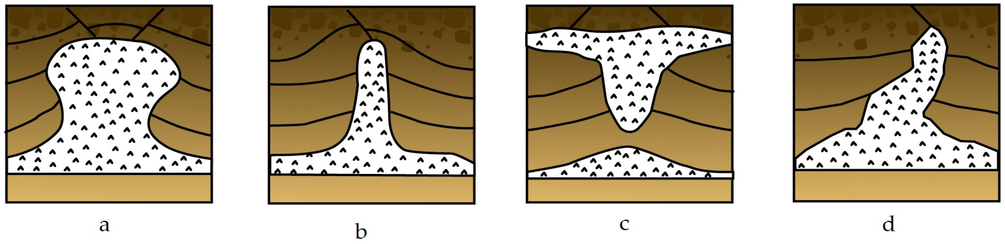
Figure 2.
Salt dome expansion stages.

Figure 3.
The role of overburden rock type in collapse of salt cavern roof.
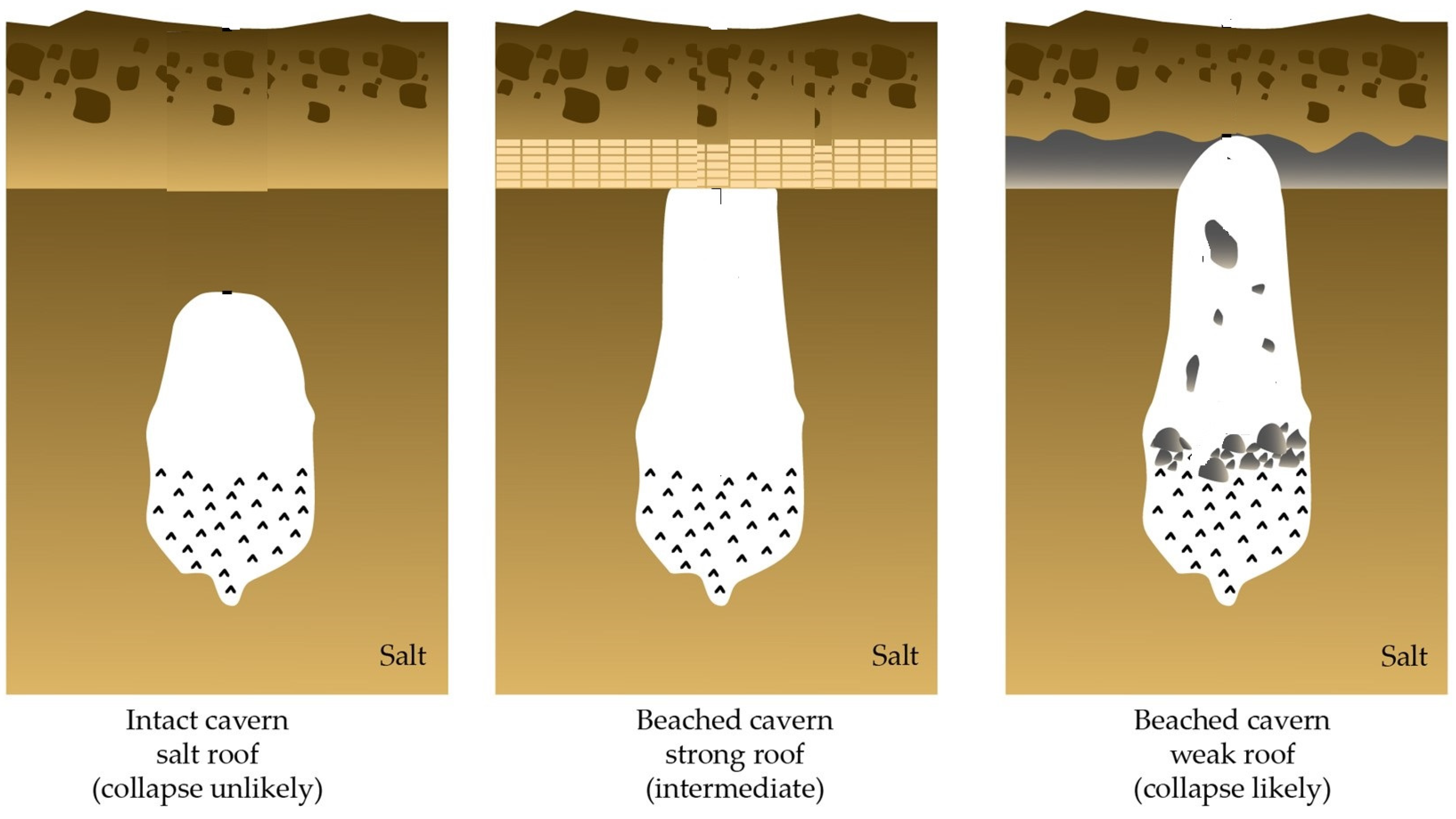
Figure 4.
The methods of salt cavern construction: (a) direct leaching, and (b) reverse leaching.

Figure 5.
Necessary measurement for preservation of well integrity in UHS projects.
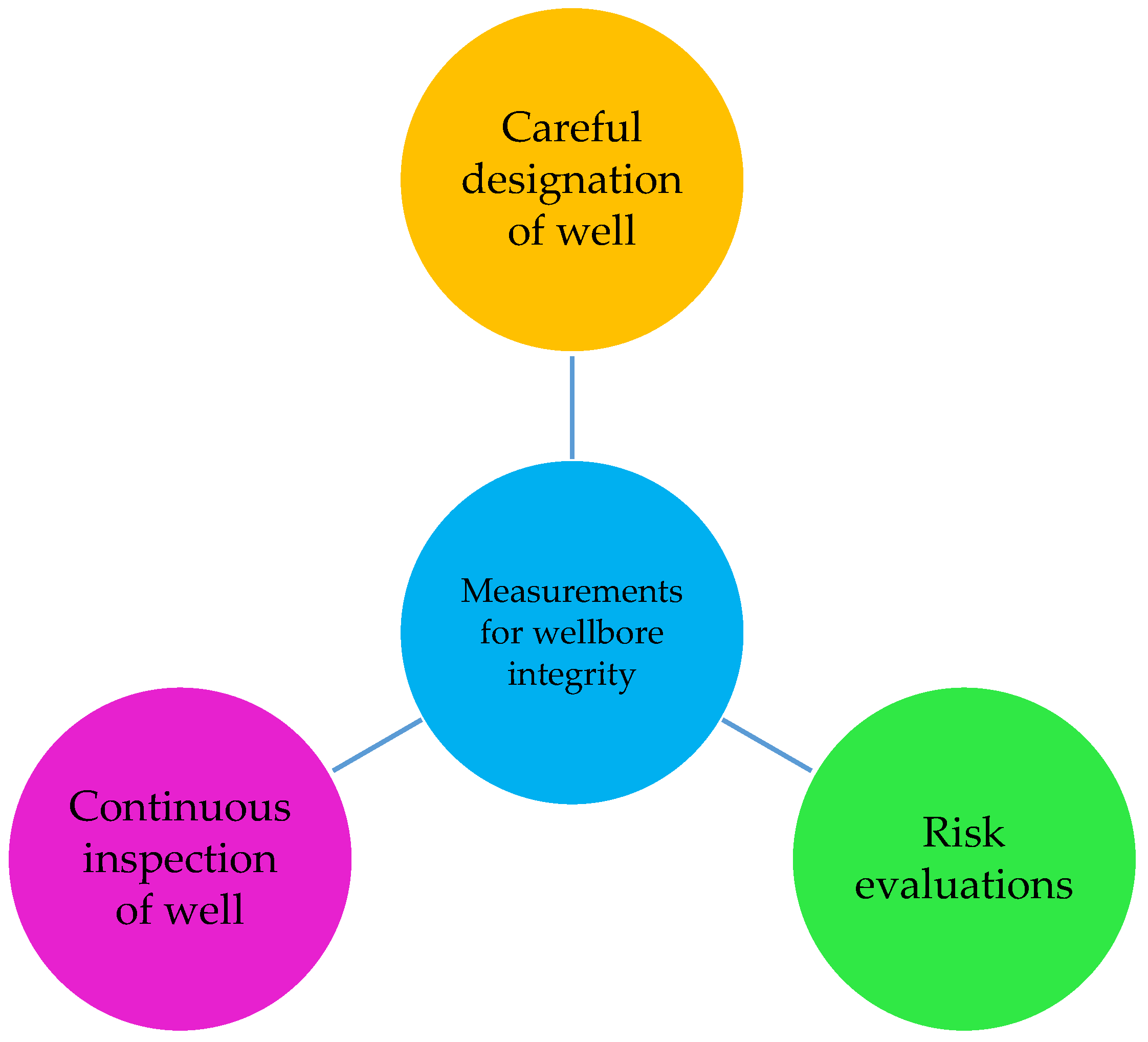

Table 1.
Some well integrity issues reported in underground storage of hydrogen and other hydrocarbons.
Table 1.
Some well integrity issues reported in underground storage of hydrogen and other hydrocarbons.
| Country | Project Location | Year | Stored Gas Type | Reported Problem | Outcomes |
|---|---|---|---|---|---|
| France | Manosque | 2012 | Diesel | Break of central column | Not reported. |
| France | Manosque | 2007 | Fuel oil | Oil leakage around wellhead | Contamination of ground surface by the leaked oil. |
| USA | Texas, Odessa | 2004 | Propane | Wellhead flange break | Air pollution by the released gas. |
| USA | Moss Bluff, Louisiana | 2004 | USA-LPG | Brine circuit leakage | A blast and fire resulted in the release of 170 cubic meters. |
| USA | Magnolia, Texas | 2003 | Natural gas | Gas leakage from casing pipe | An amount of 9.9 million cubic meters of gas were released within a few hours. |
| USA | Brenham, Texas | 1992 | LPG | Blowout of the wellbore | Huge gas release to the atmosphere as well as explosion and fire resulted in 3 deaths and 23 injuries. |
| USA | Clute, Texas | 1988 | Ethylene | Gas leakage from casing pipe | Subsurface contamination by the leaked gas. |
| USA | Mont Belvieu, Texas | 1985 | Propane | Gas leakage from casing pipe | Explosion and fire resulted in 2 deaths. |
| USA | Belvieu, Texas | 1980 | LPG | Gas leakage from casing pipe | explosion and fire. |
| USA | Mississippi | 1980 | Natural gas | Gas influx from the cement around casing | Subsurface contamination by the leaked gas. |
Disclaimer/Publisher’s Note: The statements, opinions and data contained in all publications are solely those of the individual author(s) and contributor(s) and not of MDPI and/or the editor(s). MDPI and/or the editor(s) disclaim responsibility for any injury to people or property resulting from any ideas, methods, instructions or products referred to in the content. |
© 2024 by the authors. Licensee MDPI, Basel, Switzerland. This article is an open access article distributed under the terms and conditions of the Creative Commons Attribution (CC BY) license (https://creativecommons.org/licenses/by/4.0/).
Share and Cite
MDPI and ACS Style
Zamani, O.A.M.; Knez, D. Well Integrity in Salt Cavern Hydrogen Storage. Energies 2024, 17, 3586. https://doi.org/10.3390/en17143586
AMA Style
Zamani OAM, Knez D. Well Integrity in Salt Cavern Hydrogen Storage. Energies. 2024; 17(14):3586. https://doi.org/10.3390/en17143586
Chicago/Turabian StyleZamani, Omid Ahmad Mahmoudi, and Dariusz Knez. 2024. "Well Integrity in Salt Cavern Hydrogen Storage" Energies 17, no. 14: 3586. https://doi.org/10.3390/en17143586
Note that from the first issue of 2016, this journal uses article numbers instead of page numbers. See further details here.