Article

Biogas-to-Power Systems Based on Solid Oxide Fuel Cells: Thermodynamic Analysis of Stack Integration Strategies

by
Arianna Baldinelli
1,
Umberto Desideri
1,
Francesco Fantozzi
2 and
Giovanni Cinti
2,*
1
Department of Energy, Systems, Land and Constructions Engineering (DESTEC), Università di Pisa, Largo Lucio Lazzarino, 56122 Pisa, Italy
2
Dipartimento di Ingegneria, Università degli Studi di Perugia, Via Duranti 93, 06125 Perugia, Italy
*
Author to whom correspondence should be addressed.
Energies 2024, 17(15), 3614; https://doi.org/10.3390/en17153614
Submission received: 28 May 2024 / Revised: 11 July 2024 / Accepted: 20 July 2024 / Published: 23 July 2024

Abstract

:
Biogas presents a renewable fuel source with substantial potential for reducing carbon emissions in the energy sector. Exploring this potential in the farming sector is crucial for fostering the development of small-scale distributed biogas facilities, leveraging indigenous resources while enhancing energy efficiency. The establishment of distributed biogas plants bolsters the proportion of renewable energy in the energy matrix, necessitating efficient power generation technologies. Given their proximity to bio-waste production sites like farms and digesters, optimising combined heat and power generation systems is imperative for energy self-sufficiency. Small-scale biogas facilities demand specific power generation technologies capable of achieving notable efficiencies, ranging from 40% to 55%. This study focuses on employing Solid Oxide Fuel Cells (SOFCs) in biogas-to-power systems and investigates the theoretical operation of SOFCs with fuel mixtures resulting from different biogas lean upgrading pathways. Therefore, starting from ten mixtures including CH4, CO2, H2, H2O, N2, and O2, the study proposes a method to assess their impact on the electrochemical performance, degradation, and energy equilibrium of SOFC units. The model embeds thermodynamic equilibrium, the Nernst potential, and energy balance, enabling a comprehensive comparison across these three analytical domains. The findings underscore the unsuitability of dry biogas and dry biomethane due to the potential risk of carbon deposition. Moreover, mixtures incorporating CO2, with or without H2, present significant thermal balance challenges.

1. Introduction

Binding targets of decarbonisation for the energy sector call for a wider exploitation of renewable energy sources. On the one hand, electrification is a promising driver, yet on the other hand, full electrification is not possible and advanced fuels are needed (i.e., industrial heat and power, heavy-duty mobility). Current EU legislation stresses the importance of advanced biofuels, for their carbon neutrality and their nexus to local economy development (see RED III [1] and Repower EU plan [2]). To this end, anaerobic digestion is a simple and well-known technology implemented worldwide to turn organic biowaste into a gaseous biofuel, referred to as biogas. Biogas consists of methane (50–60%vol), carbon dioxide (35–40%vol) and other minor components, such as hydrogen or nitrogen [3]. Most biogas production today comes from crops and animal manure, followed by food and green fractions from municipal solid waste and wastewater sludge processing [4]. Thanks to policy support and synergies with another challenge of modern society (waste treatment and recovery), nowadays, EU biogas production has exceeded 18 Mtoe/year (about 753 PJ/year)—as reported by International Energy Agency statistics and reports released in year 2022 [5]. The recent rise in biogas production has also been favoured because it is the primary pathway leading to biomethane synthesis [3]. To upgrade biogas to biomethane standards, the five most implemented technologies are water scrubbing, chemical scrubbing, pressure swing adsorption (PSA), membrane separation, and cryogenic separation [6]. Until 2008, water scrubbing and PSA mainly dominated the market, but recently, chemical scrubbers and membrane separation have increased their market share, the latter being the technology primarily installed in biogas upgrading facilities [7,8].
However, at present, about 60% of biogas resources are mainly used for power generation and combined heat and power (CHP) generation, while only a minor share (about 10%) supplies biomethane plants. Biogas offers a sustainable way to meet communities’ energy needs, particularly in areas with limited access to national grid supply or high heat requirements that cannot be covered just with the direct use of renewable electricity [9]. Moreover, in developing countries, biogas reduces reliance on solid biomass for cooking, improving health and economic outcomes [10].
In this framework, small-size power/CHP generators are required to connect the availability of biogas to the need for heat and power (Figure 1) against solutions which are not cost-efficient from environmental and economic points of view (namely, direct combustion and upgrading to biomethane). Electric efficiency for internal combustion engine-based (ICE) gensets typically ranges from 30% to 40%, while thermal efficiency is usually between 35% and 55%. As a rule of thumb, electrical efficiency is inversely related to installed power, unlike thermal efficiency. Electric efficiency drops for installed power below 50 kW [11]—a power range attracting much interest for the exploitation of distributed energy sources in local communities.

1.1. Small-Size High-Efficiency CHP with Fuel Cells

Fuel cells competitivity stands out clearly in the market of small-size CHP, where the electric power output dominates the thermal output. To the end of biogas conversion, high-temperature solid oxide fuel cells (SOFCs) deserve attention for several reasons [12]: (i) from a technological standpoint—whereas gas ICE efficiency drops below 30% for installed power less than 50 kW, SOFC electric performance remains stable around 50%, (ii) in terms of environmental impact—SOFCs emit neither particulate matter nor NOx gases, and SOx emissions are avoided since sulphur must be removed upstream of the SOFC to ensure safe operating conditions [13], (iii) in terms of market analysis—SOFCs have the potential to capture a specific market segment for installed power below 50 kW, distinguishing them from ICE-CHP systems and the most common biogas utilisation in small-scale combustion-based boilers.
While there are numerous benefits to integrating SOFCs into biogas facilities, the primary drawback lies in the costs and reliability due to their emerging nature as a technology [14]. Simplifying the system is anticipated to positively impact the capital costs, enhancing the influence of SOFC technology, particularly for small-scale applications. Feeding biogas as-it-is is not technically feasible in all circumstances due to impurities and high carbon content, which may affect the durable operation of the SOFC. In standard fuel cell CHP systems, methane-containing fuel gases usually undergo a pre-reforming with water steam [15]. Examples of technical analysis regarding the system layout “Biogas + Steam reforming” provide interesting results on mid-power SOFC stacks. For instance, in Ref. [16], a 25 kW system can reach up to 56.5% electrical efficiency. In other papers, the impact of the biogas pre-reformer on the quality of the biogas mixture supplied to the SOFC is investigated and electric efficiency in the range of 51–53% is found [17]. Looking at water-free systems, dry reforming system layouts are also interesting. To this end, biogas dry reforming achieves 50% electrical efficiency, while micro SOFC-CHP with anode off-gases recirculation reaches up to 46% [18]. Such high performances are not yet reached on real environment tests because the effect of degradation after many hours of operation brings the average electric efficiency below the threshold of 40%. For instance, after one year of operation, a 1 kW SOFC stack fed from a small agro-biogas plant achieved only 27% electric efficiency [19], while under clean sewage sludge biogas feeding a 2.8 kW SOFC system scored 34% electric efficiency after 700 h of operation [20]. Similarly, a 1.3 kW SOFC-CHP system using renewable feedstocks as a source of biogas demonstrated the technical feasibility of the process and achieved 38% electrical efficiency [21].
Nonetheless, many researchers have been investigating other ways to enrich biogas with other gas species, pretreating it to obtain an optimal composition for the end-user.

1.2. Advantages and Disadvantages of Biogas SOFC-CHP: A Short Review

When SOFC stacks are fed biogas with no pretreatment, the decomposition of methane into hydrogen starts with an internal dry-reforming reaction promoted by CO2 [22]. As the current density increases, water is produced at the SOFC anode, hence, contributing to hydrogen synthesis via a steam reforming pathway. However, at the cell start-up/low current densities, CO2 is the only reforming agent to convert methane molecules from biogas. CO2 in biogas may be assumed as a source of value because dry methane reforming presents a viable option to steam reforming especially in distributed biogas plants where access to pure water is limited. The use of a water purification unit in such cases results in energy losses and operational risks. However, to facilitate steam-methane reforming as a complement to dry methane reforming, additional water may be required. The additional water can be obtained through the recirculation of anode off-gas, addressing the need for water in the reforming process.
Nevertheless, two important issues need to be addressed regarding internal methane dry-reforming SOFCs [23]. Firstly, the kinetics and the role of CO2 in methane conversion has received limited attention and is not deeply understood. This lack of knowledge hinders the optimisation of the reforming process and mitigation of the thermal stress on the cell surfaces. Secondly, achieving complete chemical equilibrium conditions inside the anode fuel channel is challenging due to the short residence time onto the catalyst. This prevents entirely attaining chemical equilibrium, impacting the reforming efficiency. Additionally, it is vital to achieve a uniform distribution of fuel gas, steam, and CO2 on the anode surface. However, it should be noted that the current density distribution along the fuel channel is non-uniform, with a rapid increase from the inlet, peaking in the middle, and decreasing towards the outlet. This non-uniform current density distribution significantly increases the risk of carbon deposition at the fuel channel inlet.
To prevent carbon deposition and obtain reliable performance, one crucial parameter is the methane-to-carbon dioxide ratio of the fuel (CH4/CO2, in volume)—that is, an alternative to the oxygen–carbon ratio (O/C). Average biogas is featured by CH4/CO2 = 1.5, which is associated with a considerable risk of carbon deposition according to chemical equilibrium prediction. The composition of the SOFC feeding can be modified by system design strategies [24], such as:
  • premix with air: atmospheric air is conditioned (O2 and N2) and admixed to biogas at the SOFC inlet; this choice is aimed at achieving an internal partial oxidation that consumes methane and delivers steam to further favour methane steam reforming.
  • cold anode off-gases recirculation: after water condensation and removal, a bleeding of the anode off-gases (dry CO2 + unreacted H2, CO, and CH4) is recirculated back to the SOFC inlet and mixed with fresh biogas; it further promotes internal dry reforming.
  • hot anode off-gases recirculation: a bleeding of wet anode off-gases (H2O, CO2 + unreacted H2, CO, and CH4) is recirculated back to the SOFC inlet and mixed with fresh biogas; it promotes both internal dry and steam reforming.
All three strategies are meant to decrease the CH4/CO2 ratio. The mass ratio between the fresh biogas feeding and the recirculation bleeding/air feeding is crucial to determine the final composition. Many researchers have been trying to optimise this parameter. The experimental results reported by the literature provide evidence of operation, with CH4/CO2 mixtures ranging from 0.43 [25] (tubular NiYSZ-anode SOFC, 800 °C, 160 mA cm−2) to 3 [26] (planar NiYSZ-anode SOFC, 800 °C, 400–1600 mA cm−2). However, the equimolar mix (CH4/CO2 = 1) is claimed to be the optimal choice, as a trade-off between carbon deposition suppression and qualified performance [27].

1.3. Scope

From the literature survey, many biogas reforming concepts exist and exhibit technical feasibility at the system level. However, a comprehensive comparison of biogas-SOFC system performance with different reforming mechanisms is still lacking, particularly in mitigating the risk of carbon deposition. The experimental evidence collected on commercial cells provides a good outlook on the use of biogas, either without bulk composition modification [28] or after the addition of diluent agents [29]. However, a comprehensive approach to define operational strategies is needed.
Therefore, this paper aims to investigate the theoretical operation of SOFCs fuelled with biogas mixtures after a “lean” upgrade, that is to say, modified with simple recirculation and dilution strategies, as well as biogas derivatives obtained through external fuel processing. The paper’s main aim is to look at stable operation points characterised by a low risk for carbon deposition and good performances. Modified biogas compositions are determined to be technically achievable in small-scale systems and the investigation is carried out with a combination of methodologies, as detailed in the next sections. The methodology here presented is based on a set of simple equations, and can be used as a selection tool in more complex modelling works in order to exclude unfeasible conditions from the investigation domain.

2. Methods

The study evaluates the impact of different gas mixtures on SOFCs with a comprehensive methodology made of a set of simple tools. This section presents the investigation domain defined by the gas mixtures (Section 2.1) and the modelling methodology (Section 2.2).

2.1. Gas Mixtures Definition

Starting from a standard biogas composition, CH4:CO2 = 60:40, several options are considered based on the possibility of adding or removing chemical components to a reference gas mixture—Table 1. The compositions simulated include methane (CH4), carbon dioxide (CO2), hydrogen (H2), water (H2O), nitrogen (N2), and oxygen (O2). Species addition may be as a result of dilution, admixtures (normally gas compounds available in the environment where biogas plants usually stand are considered), and stream recycles, whereas species removal comes from upgrading, selective separation by membranes, and adsorption practice (PSA) [8]. The list of the ten gas mixtures studied is reported in Table 1, starting from dry biogas in a standard composition CH4:CO2 = 60:40 [30] (m1) and followed by so-called “dry biomethane” resulting from the total upgrading of biogas after the complete removal of carbon dioxide (m2) [31]. For both biogas and biomethane, the introduction of water (steam) is considered with a steam-to-carbon (S/C) ratio of 2 (namely, m3–m4). Then, the addition to biogas of air is considered (m5), since this practice was already reported in the experimental literature as a way to suppress fast degradation [29], as well as the separate introduction of hydrogen (m6) or oxygen (m7). The mixture of biogas with both hydrogen and oxygen is also studied (m8). The last three cases may occur where there is availability of hydrogen and oxygen, i.e., produced with an electrolyser not operating in phase with the SOFC (Power-to-X and X-to-Power layouts [32] or specifically SOC reversible operation [33]). Finally, the enrichment of biogas with CO2 is also investigated (m9) with further addition of hydrogen (m10). This circumstance may arise in the event of anode off gas recirculation after water condensation [24]; however, the specific composition depends on the recirculation ratio chosen.
The calibration of the gas compositions here presented is based on the carbon deposition analysis, as described in-depth later.

2.2. Modelling Methodology

The gas mixture compositions are investigated by looking at three main aspects: electrochemical performances, degradation, and thermal balance. When analysing the electrochemical performance of an SOFC, the polarisation curve is considered as the main characterisation. The gas mixture composition mainly impacts the polarisation curve performances in terms of the Nernst voltage and dilution of active species [34]. The Nernst voltage is the theoretical open circuit voltage (OCV). Then, the operative voltage of the cell results from the difference between the OCV and the current-dependent polarisation losses. While activation and ohmic losses are mainly dependent on the operating temperature, mass transport losses are also determined by the gas composition [35].
The study considers two main parameters for the electrochemical performances: the Nernst potential and the low heating value (LHV). The Nernst potential is calculated as follows in Equation (1), where VNernst is the Nernst voltage, R is the universal gas constant, T is the temperature, n is the number of electrons of the electrochemical reaction (4), F is the Faraday constant, and PO2cat and PO2ano are the partial pressure of oxygen at the cathode and anode, respectively [27].
V N e r n s t = R T n F l n P O 2 c a t P O 2 a n o
The oxygen partial pressure at the cathode is fixed to 0.21, since air is usually supplied to the cathode, while the oxygen partial pressure at the anode is calculated considering the thermodynamic equilibrium of the ten compositions selected at the SOFC inlet temperature. The equilibrium is calculated with the FactSage software [36]. The LHV of the gas mixture is calculated as the LHV of the fuels in the composition (CH4, CO, and H2) weighted on the relative concentration.
When running SOFCs with carbonaceous fuels, such as biogas, the main degradation is caused by carbon deposition. The chemical reaction equilibrium, enhanced by local temperatures and the presence of a catalyst, can produce solid carbon that deposits in the anode and brings rapid degradation. The risk of carbon deposition is studied in chemical equilibrium conditions and the results are reported in the ternary diagram C-H-O [37], where the selected composition can be reported as a point in the graph where the area of carbon deposition risk is highlighted, based on the solid carbon synthesis resulting at chemical equilibrium simulated with the software FactSage at a given operation temperature. (Note: A ternary diagram is a triangle-shaped graphical representation used to illustrate the compositional relationships among three components. In the case of CHO, the three components are carbon (C), hydrogen (H), and oxygen (O). These diagrams are particularly useful in the fields of chemical engineering, biomass and biofuels processes to understand the stoichiometry and balance of these elements in different substances. It is a useful visualisation tool to compare several options).
Chemical and electrochemical reactions in the anode have an important impact at the system level and contribute to the thermal equilibrium of the stack. To evaluate the thermal equilibrium, the stack is studied as a zero-dimensional system that exchanges work (electric power) and material streams (inlet/outlet enthalpy flows) with the environment. Starting from the feeding gas compositions (Table 1), the actual gas composition resulting from the operative condition of the cell is calculated considering the chemical and electrochemical reactions occurring in the cell. Namely, steam methane reforming (2) and the shift reaction (3) are considered completed. The anodic (4) and cathodic (5) electrochemical reactions are considered as follows:
C H 4 + H 2 O C O + 3 H 2
C O + H 2 O C O 2 + H 2
H 2 + O 2 H 2 O + 2 e
1 2 O 2 + 2 e O 2
A unitary-area cell is considered when accounting for the current and gas flow rates. For these reasons, the following equations refer to area-specific variables. The gas flow rates are calculated from the indirect parameter called utilisation of fuel (Uf) defined in Equation (6), where J is the operating current density (A cm−2), and n ˙ H 2 e q is the molar hydrogen equivalent flow rate (7)—namely, the amount of hydrogen available in the anode considering the reactions (2) and (3) (mol s−1 cm−2). The hydrogen equivalent flow rate is calculated with the following Equation (7), where n ˙ H 2 , n ˙ C O , n ˙ C H 4 are the molar flow rates of hydrogen, carbon monoxide, and methane, respectively. The cathodic gas flow rates can be calculated with a similar indirect parameter called utilisation of oxygen (Uox) and defined in Equation (8), n ˙ O 2 being the cathodic flow rate of oxygen—related to reaction (5).
U f = J 2 F n ˙ H 2 e q
n ˙ H 2 e q = n ˙ H 2 + n ˙ C O + 4 n ˙ C H 4
U o x = J 4 F n ˙ O 2
When the inlet and outlet gas flow rates are defined, it is possible to calculate the heat balance with the first thermodynamic principle, according to Equation (9), where Δ H ˙   represents the instantaneous heat balance, h i n ˙ is the total enthalpy flow of the inlet streams (both cathodic and anodic), h o u t ˙   is the total enthalpy flow of the outlet streams (both cathodic and anodic), CL is the thermal cell losses calculated as a fraction of the enthalpy balance, and Pe is the electrical power produced by the cell calculated as the product of the cell voltage (Vcell) and the current density—see Equation (10). Lastly, the voltage is calculated with the linear function of the current density reported by Equation (11), where for the OCV, the Nernst voltage was used. ASR is the area-specific resistance and K is a parameter that considers the impact of Uf in the performances based on experimental results—as evidenced in previous experimental work [38].
Δ H ˙ = ( h i n ˙ h o u t ˙ ) · ( 1 C L ) P e
P e = V c e l l · J
V c e l l = O C V A S R · J K · U f
The model is finally based on SOFC parameters retrieved from the literature and summarised in Table 2.

3. Results

The ten compositions were analysed using the methods presented in Section 2.2. Figure 2 reports the ternary diagram and the gas composition representation. The two blue lines in the graph indicate the limit of carbon deposition for temperatures of 700 and 800 °C, while the red dashed line is the limit for the reoxidation of the nickel. The most suitable compositions should lie between the carbon deposition and reoxidation limits. The state-of-the-art SOFC operating temperature is 750 °C [40] and the fuel inlet and outlet temperatures of the cell are usually 700 and 800 °C, respectively. In the case of the carbon deposition study, the inlet temperature of 700 °C is considered for two reasons: the chemical reactions start in the inlet, and along the cell, steam is produced by the electrochemical reactions, reducing the risk of carbon deposition. The selected compositions were tuned to obtain a point below the carbon deposition line at 700 °C, with the only exceptions of dry biomethane (m1), dry biogas (m2), and biogas + H2 (m6). The first two compositions, as expected, cannot be directly used in SOFCs, while the introduction of hydrogen moves the dry biogas composition down to the hydrogen edge (bottom left) along a line that lies entirely in the carbon deposition area. This means that the increase in hydrogen concentration does not solve the problem. Note that two compositions considering the addition of oxygen and air fall at the same zone of the graph since the presence of nitrogen is not considered in this analysis.
The composition analysis was performed also with FACTSage, considering thermodynamic equilibrium at 700 °C. The results are reported in Figure 3, where the graphene concentration is plotted for the studied compositions as the only solid carbonaceous form produced at equilibrium.
The FACTSage results agree with the ternary diagram study with the only exception of the Biogas + Air mixture (m5), where the role of nitrogen emerges as a negative factor for the synthesis of solid carbon.
Figure 4 reports the LHV values and the Nernst voltage of the studied compositions. The LHV values are strongly related to the quality and quantity of the gas mixture species concentrations. As expected, dry biomethane and dry biogas are the most concentrated mixture with the latter lower due to the presence of CO2. The introduction of all other gas streams leads to a decrease in the LHV, and even when a new fuel is added, e.g., hydrogen, the methane concentration is reduced. It is interesting to note how the introduction of H2 and O2 produces close results. This result is related to the concentration of the species: while the oxygen concentration is c.a. 25%, hydrogen reaches up to 50%, with an opposite impact in the methane concentration. Looking to the Nernst voltage, the obtained values range from 1.12 V of Biogas + H2 (m6), down to 1.04 V per Biogas S:C 2. It is highlighted that the Nernst calculation is not possible for dry biomethane (m2), since the oxygen concentration at the anode is zero (no oxygen compounds available).
Figure 5 reports the results of the thermal balance analysis. The thermal balance is the result of chemical and electrochemical equilibrium, and it is strongly dependent on the inlet gas mix.
Both biomethane mixtures, with and without steam addition (namely, m2 and m4), are the only two with a negative balance. This means that the cell requires to be cooled due to the high concentration of inlet methane (see LHV values), which is completely oxidised in the cell. Both Biogas + CO2 mixtures (m9 and m10) have a highly positive balance due to the dominant role of CO2 that in the considered reactions is not involved as a reacting species and becomes inert, needing to be heated in the cell. It is possible to obtain a neutral thermal balance by changing the utilisation of the oxygen and gas inlet temperature parameters, but the variation in these two parameters is very limited and solutions at the system level are necessary.

4. Discussion

The results reported in this study are a preliminary overview of the path for modifying biogas composition to improve performance in SOFCs in terms of power production, durability, and system integration. All the compositions considered can be obtained by adding or removing pure gases from the gas mixtures—what is here referred to as “lean” upgrading. In the case of new gas compounds admixture, the feasibility of this strategy depends on the local availability of the required additional feedstock. In any case, a technological process has to be introduced and integrated in the system and impacts the system balance and gross system efficiency. Moreover, inlet SOFC gases are introduced at high temperatures, 700 °C, and a heat balance is required considering the hot gases available in the system (e.g., SOFC exhausts). In the following, each specific gas process technology is briefly introduced:
(a)
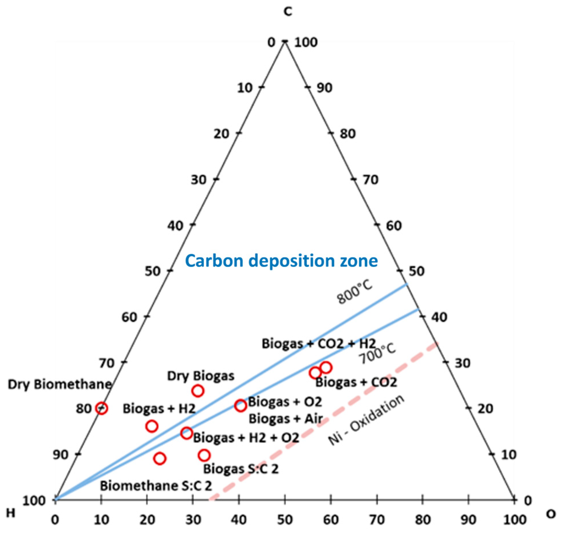
Carbon dioxide is the only pure gas that can be either removed or added to the mixture. The separation of CO2 from biogas is a well-known and state-of-the-art technology. The most diffused technological solutions are membrane and PSA separation. Both technologies require an energy input, thereby impacting the system’s energy performances. Looking at the process quality, the amount of CO2 separated varies from dry biogas to dry methane in a high-risk carbon deposition area, as reported in Figure 2. The introduction of additional CO2 in compositions m9 and m10 can be obtained by recycling the SOFC anode gas exhausts. In this case, depending on the system design, CO2 has to be separated from hydrogen and steam with a cooling and separation process based on the previously listed technologies.
(b)
Air can be easily obtained from the ambient atmosphere with the only requirement in terms of filter and compression with a blower. Note that the SOFC already has an air feeding line for the cathode that can be partially used for the anode also.
(c)
Water can be partially, or completely, recovered from the anode exhausts after the condensation of the outlet gas stream. Then, water steam can be produced with a steam generator recovering heat from the exhausts or with an additional heat duty for the system.
(d)
Looking at hydrogen, two separate strategies can be implemented. On the one hand, hydrogen can be recycled from the gas exhausts. As for CO2, separation from the other species is necessary. In the case of both CO2 and H2, an integrated strategy can be implemented with an optimised tuning for the requested composition. On the other hand, hydrogen can be produced with an additional energy technology. The most interesting option is to consider an electrolyser fed with a renewable energy source, such as solar photovoltaic. In this case, and depending on the electrolyser technology, additional scenarios in terms of energy storage and system integration strategies can be considered—for instance, the water necessary for the electrolysis can be an additional external feedstock requirement or can be recovered from the anode exhausts as in the steam case.
(e)
Oxygen can be produced from the separation of air or the electrolysis of water. The latter option seems more interesting in the case hydrogen is also required.
In general, each process for pure gas production of reparation brings additional energy requirements that may impact the total energy balance depending on the selected technology.

5. Conclusions

The study aims to identify potential strategies for utilising biogas directly in SOFCs for power production. Specifically, the impact of introducing or removing pure gas streams on SOFC performance was investigated. Three distinct impacts were analysed individually with a combined modelling approach. It was found that the composition of dry biogas and dry biomethane poses significant risks in terms of carbon deposition. The introduction of pure air and of pure hydrogen does not guarantee safe operation in terms of solid carbon formation. Looking at carbon dilution, the LHV parameter, dry biogas, and dry biomethane are the best performing. In general, the LHV of the gas mixture is primarily influenced by the concentration of methane. The analysis of the Nernst potential reveals that introducing hydrogen enhances performance, particularly when starting with a composition of Biogas + O2 or Biogas + CO2. Furthermore, the thermal balance study highlights that for CO2-enriched compositions (the last two in the list), a significant amount of external heat needs to be provided. Defining a single parameter for evaluating the different compositions is challenging.
The methodology here presented appears helpful in the pre-assessment of biogas-based fuel mixtures or specific operating conditions arising from outlet gases recirculation in SOFCs. As concluded by the application of the methodology in this work, dry biogas and dry biomethane can be excluded, since their use is strongly limited due to the carbon deposition.

Author Contributions

Conceptualisation, A.B. and G.C.; methodology, G.C.; validation, A.B.; formal analysis, G.C.; investigation, A.B. and G.C.; writing—original draft preparation, A.B. and G.C.; writing—review and editing, F.F. and U.D.; visualisation, A.B.; supervision, F.F. and U.D.; project administration, G.C.; funding acquisition, G.C. and U.D. All authors have read and agreed to the published version of the manuscript.

Funding

This research was funded in the framework of: (1) the National Recovery and Resilience Plan (NRRP), Mission 4, Component 2 Investment 1.3—Call for tender No. 1561 of 11.10.2022 of Ministero dell’Università e della Ricerca (MUR), funded by the European Union—NextGenerationEU. Award Number: Project code PE0000021, Concession Decree No. 1561 of 11.10.2022 adopted by Ministero dell’Università e della Ricerca (MUR), CUP—I53C22001450006, Project title “Network 4 Energy Sustainable Transition—NEST”, (2) the ERASMUS+ project “H2Excellence”, Grant Agreement number 101104447.

Data Availability Statement

All relevant data are provided in the Tables and Figures displayed in the manuscript.

Conflicts of Interest

The authors declare no conflict of interest.

Nomenclature

ASR Area Specific Resistance; CHP Combined Heat and Power; ICE Internal Combustion Engine; LHV Low Heating Voltage; NOx Nitrogen Oxides; OCV Open Circuit Voltage; PSA Pressure Swing Adsorption; SOFC Solid Oxide Fuel Cell; Sox Sulphur Oxides; Uf Fuel Utilisation.

References

  1. European Commission. Directive (Eu) 2023/2413 of the European Parliament and of the Council; European Commission: Brussels, Belgium; Luxembourg, 2023. [Google Scholar]
  2. European Commission. Communication from the Commission to the European Parliament, the European Council, the Council, the European Economic and Social Committee and the Committee of the Regions REPowerEU Plan; European Commission: Brussels, Belgium; Luxembourg, 2022. [Google Scholar]
  3. Kaur, G.; Basak, N.; Kumar, S. State-of-the-art techniques to enhance biomethane/biogas production in thermophilic anaerobic digestion. Process Saf. Environ. Prot. 2024, 186, 104–117. [Google Scholar] [CrossRef]
  4. Tricase, C.; Lombardi, M. State of the art and prospects of Italian biogas production from animal sewage: Technical-economic considerations. Renew. Energy 2009, 34, 477–485. [Google Scholar] [CrossRef]
  5. International Energy Agency IEA. Outlook for Biogas and Biomethane: Prospects for Organic Growth—World Energy Outlook Special Report. 2022. Available online: https://www.iea.org/reports/outlook-for-biogas-and-biomethane-prospects-for-organic-growth (accessed on 15 January 2024).
  6. Sun, Q.; Li, H.; Yan, J.; Liu, L.; Yu, Z.; Yu, X. Selection of appropriate biogas upgrading technology-a review of biogas cleaning, upgrading and utilisation. Renew. Sustain. Energy Rev. 2015, 51, 521–532. [Google Scholar] [CrossRef]
  7. Bauer, F.; Hulteberg, C.; Persson, T.; Tamm, D. Biogas Upgrading—Review of Commercial Technologies (Biogasuppgradering—Granskning av Kommersiella Tekniker); Svenskt Gastekniskt Center (SGC): Malmoe, Sweden, 2013. [Google Scholar]
  8. Gkotsis, P.; Kougias, P.; Mitrakas, M.; Zouboulis, A. Biogas upgrading technologies—Recent advances in membrane-based processes. Int. J. Hydrogen Energy 2023, 48, 3965–3993. [Google Scholar] [CrossRef]
  9. Klavon, K.H.; Lansing, S.A.; Mulbry, W.; Moss, A.R.; Felton, G. Economic analysis of small-scale agricultural digesters in the United States. Biomass Bioenergy 2013, 54, 36–45. [Google Scholar] [CrossRef]
  10. The World Bank. Promoting Biogas as Sustainable Clean Cooking Fuel for Rural Households in Kenya Project; Proj. Rep., No. Report No: 101650-KE; The World Bank: Washington, DC, USA, 2016. [Google Scholar]
  11. Simader, G.R.; Krawinkler, R.; Trnka, G. Micro CHP Systems: State-of-the-Art; Austrian Energy Agency: Vienna, Austria, 2006. [Google Scholar]
  12. Baldinelli, A.; Barelli, L.; Bidini, G.; Cinti, G. Micro-cogeneration based on solid oxide fuel cells: Market opportunities in the agriculture/livestock sector. Int. J. Hydrogen Energy 2021, 46, 10036–10048. [Google Scholar] [CrossRef]
  13. Boldrin, P.; Millan-Agorio, M.; Brandon, N.P. Effect of sulfur- and tar-contaminated syngas on solid oxide fuel cell anode materials. Energy Fuels 2015, 29, 442–446. [Google Scholar] [CrossRef]
  14. Baldinelli, A.; Barelli, L.; Bidini, G. On the feasibility of on-farm biogas-to-electricity conversion: To what extent is solid oxide fuel cells durability a threat to break even the initial investment? Int. J. Hydrogen Energy 2018, 43, 16971–16985. [Google Scholar] [CrossRef]
  15. Bae, J. Fuel Processor Lifetime and Reliability in Solid Oxide Fuel Cells; Elsevier Ltd.: Amsterdam, The Netherlands, 2017. [Google Scholar] [CrossRef]
  16. Tjaden, B.; Gandiglio, M.; Lanzini, A.; Santarelli, M.; Ja, M. Small-Scale Biogas-SOFC Plant: Technical Analysis and Assessment of Different Fuel Reforming Options. Energy Fuels 2014, 28, 4216–4232. [Google Scholar] [CrossRef]
  17. Trendewicz, A.A.; Braun, R.J. Techno-economic analysis of solid oxide fuel cell-based combined heat and power systems for biogas utilization at wastewater treatment facilities. J. Power Sources 2013, 233, 380–393. [Google Scholar] [CrossRef]
  18. Kupecki, J.; Skrzypkiewicz, M.; Wierzbicki, M.; Stepien, M. Analysis of a Micro-CHP Unit with in-series SOFC Stacks Fed by Biogas. Energy Procedia 2015, 75, 2021–2026. [Google Scholar] [CrossRef]
  19. Sulzer Hexis SOFC Systems for Biogas and Heating Oil. Available online: https://www.osti.gov/etdeweb/biblio/20375397 (accessed on 5 April 2024).
  20. BIOCELL—Energy Self-Sustaining and Environmental Footprint Reduction on Wastewater Treatment Plants via Fuel Cells. Available online: https://webgate.ec.europa.eu/life/publicWebsite/index.cfm?fuseaction=search.dspPage&n_proj_id=3279 (accessed on 8 February 2024).
  21. Jahn, M.; Heddrich, M. Brennstoffzellen für Biogas: Aufbau und Betrieb Eines Sofc-Systems. In Biotechnologische Energieumwandlung: Gegenwärtige Situation, Chancen und Künftiger Forschungsbedarf; Bley, T., Ed.; Springer: Berlin, Heidelberg, 2009. [Google Scholar] [CrossRef]
  22. Kushi, T. Performance and durability evaluation of dry reforming in solid oxide fuel cells. Int. J. Hydrogen Energy 2016, 41, 17567–17576. [Google Scholar] [CrossRef]
  23. Lin, Y.; Zhan, Z.; Barnett, S.A. Improving the stability of direct-methane solid oxide fuel cells using anode barrier layers. J. Power Sources 2006, 158, 1313–1316. [Google Scholar] [CrossRef]
  24. Ma, S.; Loreti, G.; Wang, L.; Maréchal, F.; Van Herle, J.; Dong, C. Comparison and optimization of different fuel processing options for biogas-fed solid-oxide fuel cell plants. Int. J. Hydrogen Energy 2022, 47, 551–564. [Google Scholar] [CrossRef]
  25. Santarelli, M.; Quesito, F.; Novaresio, V.; Guerra, C.; Lanzini, A.; Beretta, D. Direct reforming of biogas on Ni-based SOFC anodes: Modelling of heterogeneous reactions and validation with experiments. J. Power Sources 2013, 242, 405–414. [Google Scholar] [CrossRef]
  26. Pillai, M.; Lin, Y.; Zhu, H.; Kee, R.J.; Barnett, S.A. Stability and coking of direct-methane solid oxide fuel cells: Effect of CO2 and air additions. J. Power Sources 2010, 195, 271–279. [Google Scholar] [CrossRef]
  27. Saadabadi, S.A.; Illathukandy, B.; Aravind, P.V. Direct internal methane reforming in biogas fuelled solid oxide fuel cell; the influence of operating parameters. Energy Sci. Eng. 2021, 9, 1232–1248. [Google Scholar] [CrossRef]
  28. Baldinelli, A.; Subotic, V.; Mondi, F.; Di Michele, A.; Barelli, L.; Bidini, G. Quick degradation detection on biogas-fuelled SOFCs. ECS Trans. 2019, 91, 1571. [Google Scholar] [CrossRef]
  29. Baldinelli, A.; Barelli, L.; Bidini, G.; Di Michele, A.; Vivani, R. SOFC direct fuelling with high-methane gases: Optimal strategies for fuel dilution and upgrade to avoid quick degradation. Energy Convers. Manag. 2016, 124, 492–503. [Google Scholar] [CrossRef]
  30. The Biogas. Available online: http://www.biogas-renewable-energy.info/biogas_composition.html (accessed on 5 April 2024).
  31. Makaruk, A.; Miltner, M.; Harasek, M. Membrane biogas upgrading processes for the production of natural gas substitute. Sep. Purif. Technol. 2010, 74, 83–92. [Google Scholar] [CrossRef]
  32. Wang, L.; Zhang, Y.; Pérez-Fortes, M.; Aubin, P.; Lin, T.E.; Yang, Y.; Maréchal, F. Reversible solid-oxide cell stack based power-to-x-to-power systems: Comparison of thermodynamic performance. Appl. Energy 2020, 275, 115330. [Google Scholar] [CrossRef]
  33. Baldinelli, A.; Staffolani, A.; Nobili, F.; Barelli, L. Detailed experimental analysis of solid oxide cells degradation due to frequent fuel cell/electrolyser switch. J. Energy Storage 2023, 73, 109117. [Google Scholar] [CrossRef]
  34. NETL. Fuel Cell Handbook, 7th ed.; NETL: Morgantown, WV, USA, 2004. [Google Scholar]
  35. Hanna, J.; Lee, W.Y.; Shi, Y.; Ghoniem, A.F. Fundamentals of electro- and thermochemistry in the anode of solid-oxide fuel cells with hydrocarbon and syngas fuels. Prog. Energy Combust. Sci. 2014, 40, 74–111. [Google Scholar] [CrossRef]
  36. Thermfact/CRCT and GTT-Technologies. Fact Sage. Available online: https://factsage.com/ (accessed on 8 February 2024).
  37. Sasaki, K.; Teraoka, Y. Equilibria in Fuel Cell Gases. J. Electrochem. Soc. 2003, 150, A885. [Google Scholar] [CrossRef]
  38. Barelli, L.; Bidini, G.; Cinti, G. Operation of a Solid Oxide Fuel Cell Based Power System with Ammonia as a Fuel: Experimental Test and System Design. Energies 2020, 13, 6173. [Google Scholar] [CrossRef]
  39. Cinti, G.; Liso, V.; Araya, S.S. Design improvements for ammonia-fed SOFC systems through power rating, cascade design and fuel recirculation. Int. J. Hydrogen Energy 2023, 48, 15269–15279. [Google Scholar] [CrossRef]
  40. Peters, R.; Deja, R.; Engelbracht, M.; Frank, M.; Blum, L.; Stolten, D. Efficiency analysis of a hydrogen-fueled solid oxide fuel cell system with anode off-gas recirculation. J. Power Sources 2016, 328, 105–113. [Google Scholar] [CrossRef]
Figure 1. Bio CHP: conceptual scheme.
Energies 17 03614 g001
Figure 2. CHO ternary diagram of the analysed compositions (the three axes report molar fractions of each element, and the composition of any point within the triangle sums to 100%). Blue lines mark the carbon deposition zone limits at 700 °C and 800 °C, while the red dashed line highlights the occurrence of Ni oxidation.
Energies 17 03614 g002
Figure 3. Graphene concentration for the compositions resulting from FACTSage simulations.
Energies 17 03614 g003
Figure 4. LHV and Nernst voltage of the analysed compositions.
Energies 17 03614 g004
Figure 5. Thermal balance analysis.
Energies 17 03614 g005
Table 1. Gas mixtures composition studied as SOFC fuels.
#NameCH4CO2H2H2ON2O2
m1Dry Biogas60.0%40.0%0.0%0.0%0.0%0.0%
m2Dry Biomethane100.0%0.0%0.0%0.0%0.0%0.0%
m3Biogas S:C 220.0%13.3%0.0%66.7%0.0%0.0%
m4Biomethane S:C 233.3%0.0%0.0%66.7%0.0%0.0%
m5Biogas + Air23.3%15.6%0.0%0.0%48.3%12.8%
m6Biogas + H230.0%20.0%50.0%0.0%0.0%0.0%
m7Biogas + O245.1%30.1%0.0%0.0%0.0%24.8%
m8Biogas + H2 + O225.7%17.1%42.9%0.0%0.0%14.3%
m9Biogas + CO223.1%76.9%0.0%0.0%0.0%0.0%
m10Biogas + CO2 + H221.5%71.7%6.7%0.0%0.0%0.0%
Table 2. Cell parameters used for the thermal balance calculations.
ParameterValueReference
Uf80%[39]
Uox20%[39]
Gas inlet temperature700 °C[40]
Gas outlet temperature 800 °C[40]
Current density—A cm−20.50 Acm−2[40]
CL 5%[38]
ASR0.28 Ωcm−2[39]
K0.17 V[38]
Disclaimer/Publisher’s Note: The statements, opinions and data contained in all publications are solely those of the individual author(s) and contributor(s) and not of MDPI and/or the editor(s). MDPI and/or the editor(s) disclaim responsibility for any injury to people or property resulting from any ideas, methods, instructions or products referred to in the content.

