Article

Advanced Static Var Generator in the Reactive Power Automatic Compensation System of an Underground Mine with a Thyristor Hoisting Machine

Faculty of Electrical Engineering, Silesian University of Technology, 44-100 Gliwice, Poland
*
Author to whom correspondence should be addressed.
Energies 2024, 17(15), 3628; https://doi.org/10.3390/en17153628
Submission received: 21 June 2024 / Revised: 17 July 2024 / Accepted: 23 July 2024 / Published: 24 July 2024
(This article belongs to the Special Issue Power Quality Monitoring with Energy Saving Goals)

Abstract

:
In industrial plants with dynamically varying load profiles, the problem of increased charges for over-contracted reactive power consumption is very common. To eliminate these charges, reactive power compensation systems are used. This article presents a case study of an automatic reactive power compensation system in an underground mine where a thyristor hoisting machine is used. To reduce the higher current harmonics of the hoisting machine and compensate for the reactive power of the PCC (Point of Common Coupling), the main reactive power automatic compensation system and an ASVG (Advanced Static Var Generator) with a nonstandard control loop were used. The article considers aspects of the operation of the ASVG, locally with the hoisting machine, and also as a master-controlled device that is part of the reactive power automatic compensation system. This part of the article is based on measurements taken in a mine. The reactive power automatic compensation system considered in this article has been successfully implemented, improving PQ (Power Quality) and eliminating additional overcompensation charges.

1. Introduction

The purpose of reactive power compensation is to relieve the grid of reactive current flow, which is achieved by eliminating the phase shift between the fundamental current and voltage and eliminating the higher harmonics of the load currents, regardless of the shape of the voltage. Thanks to this, the current and apparent power of the source are minimized for a specific active power of the load.
In industrial power grids, partial compensation is generally used, which consists of compensating reactive power of the fundamental current and voltage to maintain the value of the power coefficient tg φ (defined as the ratio of reactive power to active power for the fundamental current and voltage) within the permitted limits and, therefore, to reduce active power losses and voltage drops in power lines [1,2,3,4,5]. The permissible range for the power coefficient tg φ is established in order to ensure adequate stability of the power system and the ability to maintain the grid voltage at a standardized level. For this purpose, capacitor banks, passive higher harmonic filters, and synchronous compensators are used, both in the form of unloaded synchronous machines and loaded synchronous motors or generators [1,2,3,4,6,7,8,9].
However, modern power supply systems based on power electronic converters do not allow the impact of higher harmonics on the power grid and the related adverse phenomena to be omitted.
The distorted current by nonlinear load (e.g., the power electronic converter) causes a voltage drop on the impedance of the power grid, which, in turn, also causes distortion of the supply voltage and, consequently, may result in disruptions in the operation of other devices. The distortion of the voltage-supplying power electronic converters may cause synchronization errors of control signals in the vicinity of the voltage wave’s zero crossing, and consequently, the generation of noncharacteristic harmonics by such converters, including even triple harmonics and interharmonics [7]. The possible flow of the third harmonic through the neutral wire may lead to its overheating and, consequently, to the risk of fire. Higher harmonics may cause resonance phenomena in cable lines with large line-to-line capacitances, which may lead to overvoltage at specific points in the power system [9]. They also cause the insulation to age faster [10]. They may also lead to overload of capacitor banks, used to compensate reactive power, that are not protected by detuning reactors, and, consequently, to their failure or protection shut-off [5,9].
Current distortions adversely affect magnetic elements, causing an increase in losses in transformers and reactors (e.g., eddy currents, connections, and structural parts stray losses) [10]. These result in an increase in their operating temperature, excessive wear, and, consequently, a reduced MTBF (Mean Time Between Failures) [11,12]. These additional losses also reduce the efficiency of the power system [2]. In rotating machines, higher harmonics can result in adverse torques, which can act opposite to the torque of the fundamental harmonic component. Parasitic torques can increase drivetrain vibration, which can lead to premature wear of the machine bearings. The higher harmonics (above 50th order) may even cause disruptions in the operation of telecommunications and telemechanical systems, but these harmonics are well dumped by capacitances of cables and other devices.
For the aforementioned reasons, efforts are being made both to compensate the fundamental reactive power and to reduce the content of higher current harmonics, which ultimately lead to a reduction in grid voltage distortion.
PQ is characterized by a number of indicators specified in the standards, such as power frequency, voltage magnitude, voltage fluctuation and flicker, voltage harmonics and interharmonics, voltage imbalance, grid signaling voltage, voltage interruptions, voltage dips and rises, undervoltage, and overvoltage [11,13,14]. The standards also recommend limits for current and voltage distortion [8,13,14]. In addition to the aforementioned ratios, it is important from the customer’s point of view to maintain in the PCC the appropriate power parameters imposed by the DSO (Distribution System Operator). The DSO charges penalty fees for the power factor outside the allowed range, which can significantly affect the total electricity bill [6].
However, it is worth taking any action to reduce the adverse impact of nonlinear loads on the power grid, regardless of the achieved numerical values of the PQ indicators. The aim of the article is not to evaluate the compliance of electricity quality standards (which requires performing a number of measurements with specialized equipment under specific conditions [11,12]), but to discuss the impact of including ASVG in a mine’s automatic reactive power compensation system on PQ in PCC.

2. Materials and Methods

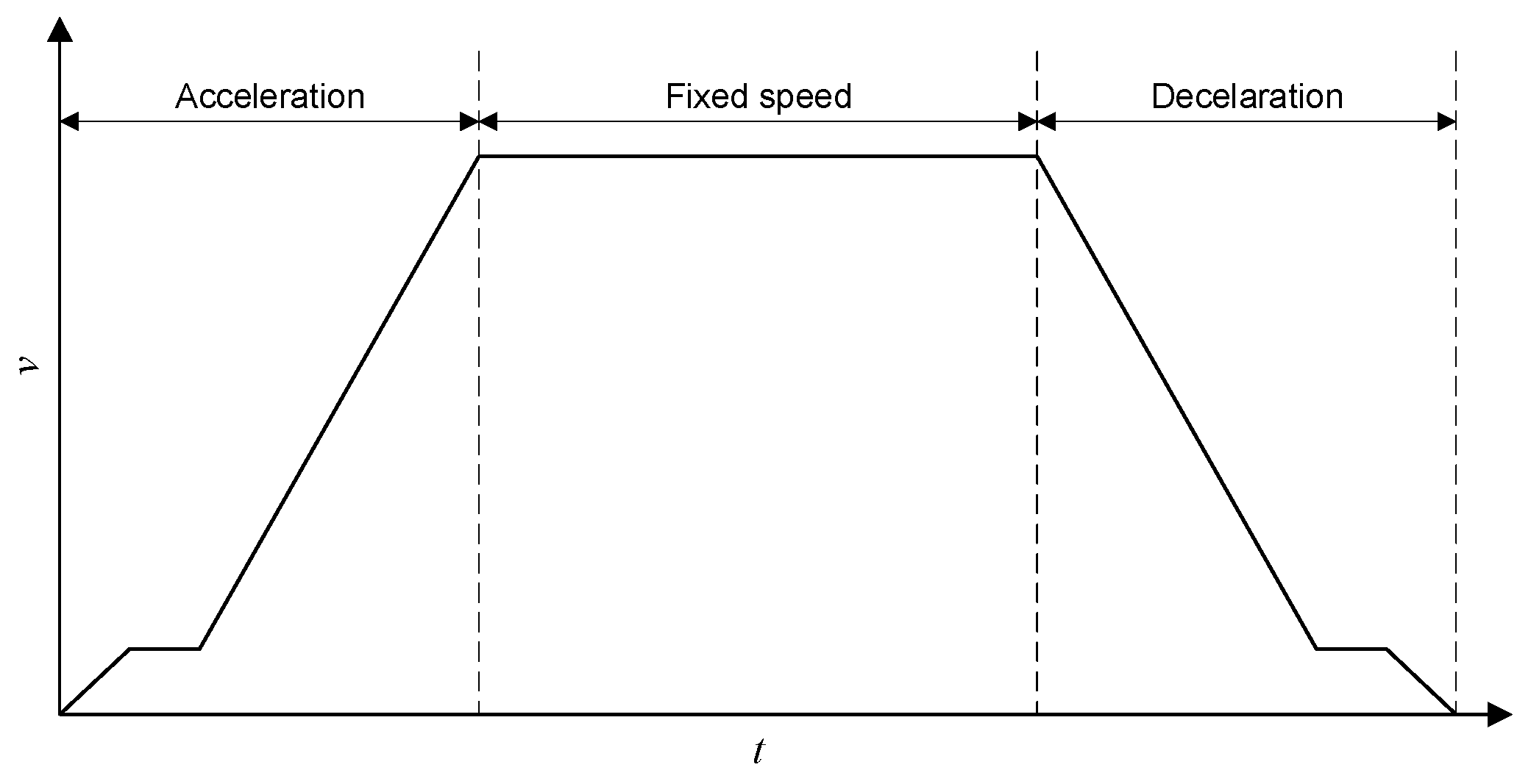
2.1. The Impact of Hoisting Machines on the PQ of the Mine Power Grid

In underground mine power supply systems, due to their relatively large power, hoisting machines are one of the most important consumers of electrical energy [6,7,11,12,15]. In hoisting machine drive systems, AC or DC motors are used. In Polish mines, the most common drives are currently DC drives powered by 12-pulse thyristor rectifiers. Hoisting machines are highly variable loads, characterized by large load changes during a relatively short duty cycle [6,15], which causes them to become a source of numerous disturbances in the plant’s power grid, such as fast voltage fluctuations (flickers). Large active and reactive power surges, especially during acceleration (start-up), significantly affect the PQ and operating conditions of power system components and are difficult to compensate for by follow-up systems without active filters. In machines powered by thyristor rectifiers, they are also significant sources of variable higher current harmonics during the duty cycle of the hoisting machine [7,11,15].
Each duty cycle of the hoisting machine consists of three phases: starting, steady driving, and braking [15,16]. Between the duty cycles, there is a rest state to load and empty the skips. Figure 1 shows a typical speed diagram of a hoisting machine during one duty cycle.
Figure 2 shows a diagram of the power supply system for a hoisting machine with a DC motor powered by a 12-pulse rectifier [10,15,16].
The speed control of the thyristor hoisting machine is achieved by changing the firing angle of the thyristors according to the driving pattern, taking into account permissible accelerations and decelerations and stabilizing the speed during steady driving. The most unfavorable part of the duty cycle, considering the impact on the power grid, is related to the acceleration of the hoisting machine. This is when the highest level of reactive inductive power consumed by the drive system occurs, which is undesirable for the grid [15]. To reduce the reactive power surge when starting the hoisting machine, asymmetrical control of the thyristors of the rectifier powering the machine is used [15,16,17,18,19,20,21]. Figure 3 shows the idea of asymmetrical control of thyristors.
The active and reactive power of a 12-pulse rectifier is the total power required by the two 6-pulse rectifiers and depends on individual firing angles control [20,21]. Asymmetrical control of thyristors involves firing the thyristors of one of the 6-pulse rectifiers with a constant angle, and the firing angle of the thyristors of the other 6-pulse rectifier is changed in such a way as to obtain the desired voltage on the DC side [22]. With this control method, the maximum fundamental reactive power is less than twice the value of the maximum reactive power consumed by each of the 6-pulse rectifiers; that is, less than the maximum reactive power consumed by the symmetrically controlled 12-pulse rectifier.
The active power of a 12-pulse rectifier with asymmetrical control can be expressed as [17,18,19,22,23]
P = P max ( cos ( α Y ) + cos ( α Δ ) ) ,
and reactive power as
Q = P max ( sin ( α Y ) + sin ( α Δ ) ) ,
where
P max = P max Y + P max Δ ,
and PmaxY and PmaxΔ are the maximum active power of rectifiers Y and Δ at firing angles equal to 0 [23]. In practice, due to the limitation of the minimum and maximum firing angle of the thyristors, asymmetrical control allows reducing the reactive power consumption by less than half [15].
Figure 4 shows typical active and reactive power waveforms of a thyristor hoisting machine during the duty cycle with symmetrical (αY = αΔ = var) and asymmetrical (αY = var, αΔ = const = 30°) control, obtained by simulation for a large-power DC motor with the same loading conditions of the hoisting machine and the same driving diagram. A simulation model of the system built in the Matlab–Simulink environment and a discussion of the results obtained from conducted research are presented in [16]. Due to the simulation time, the steady-state driving condition was shortened in relation to the real duty cycle of the hoisting machine.
The results of the simulation studies in Figure 4 confirm the favorable decrease in reactive power of the hoisting machine with asymmetric control of the thyristor rectifier, especially during machine acceleration.

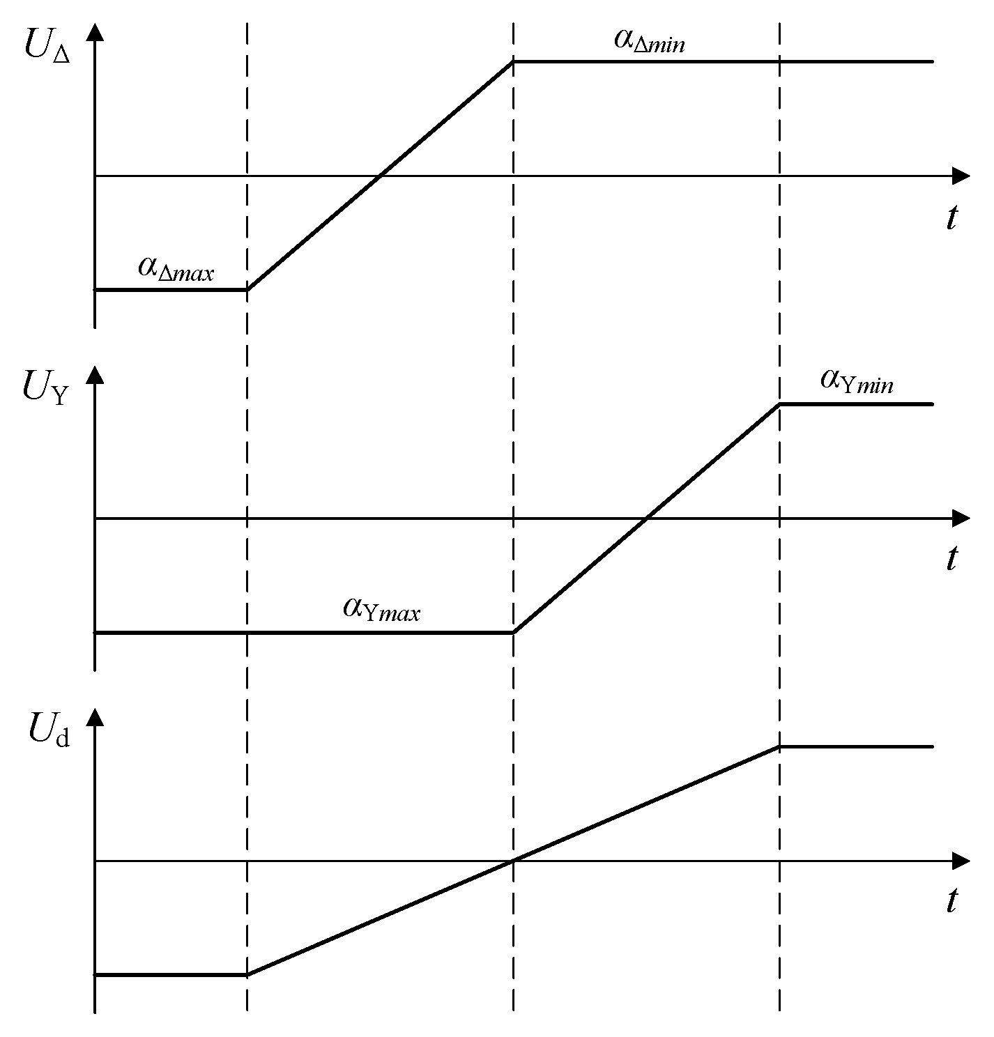
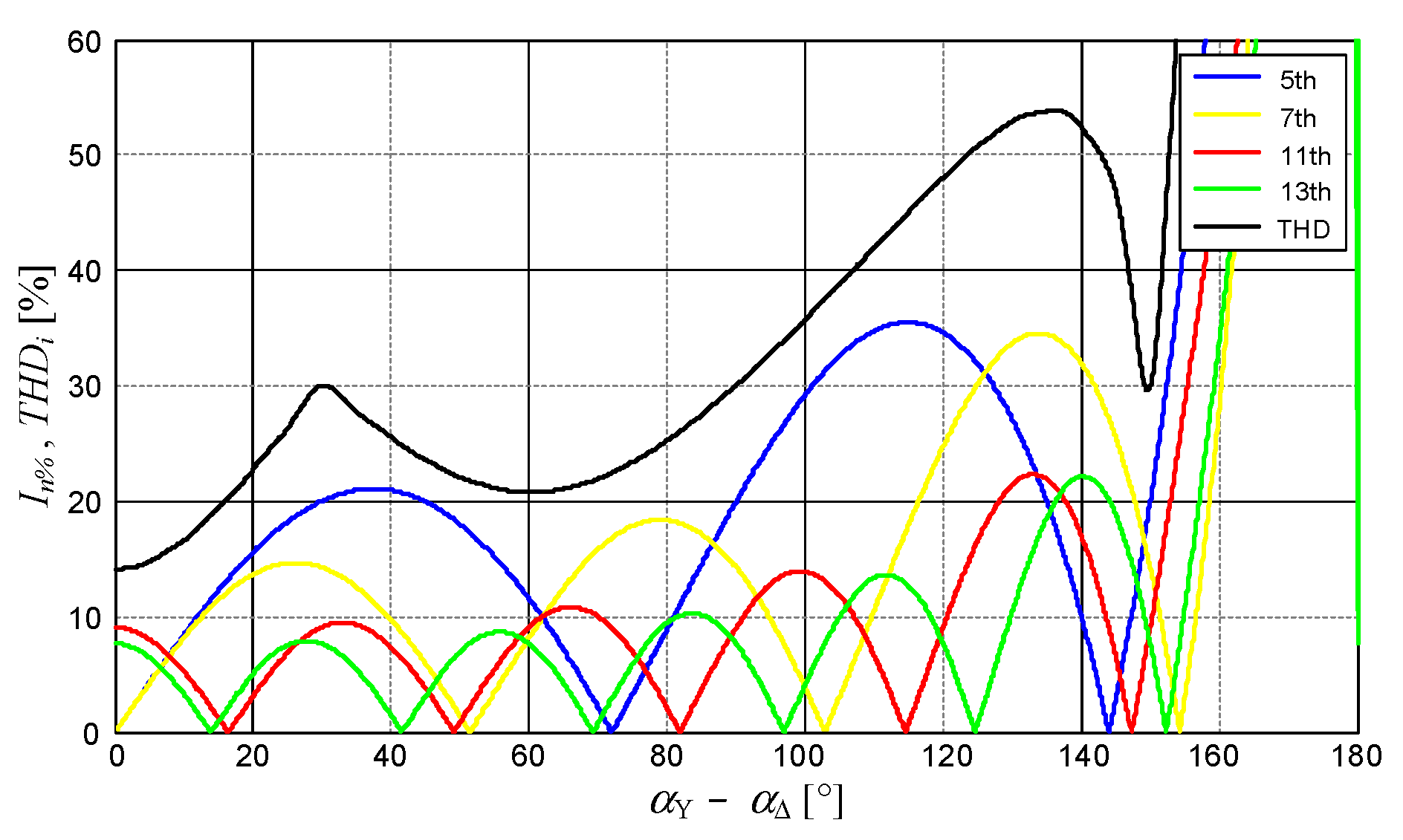
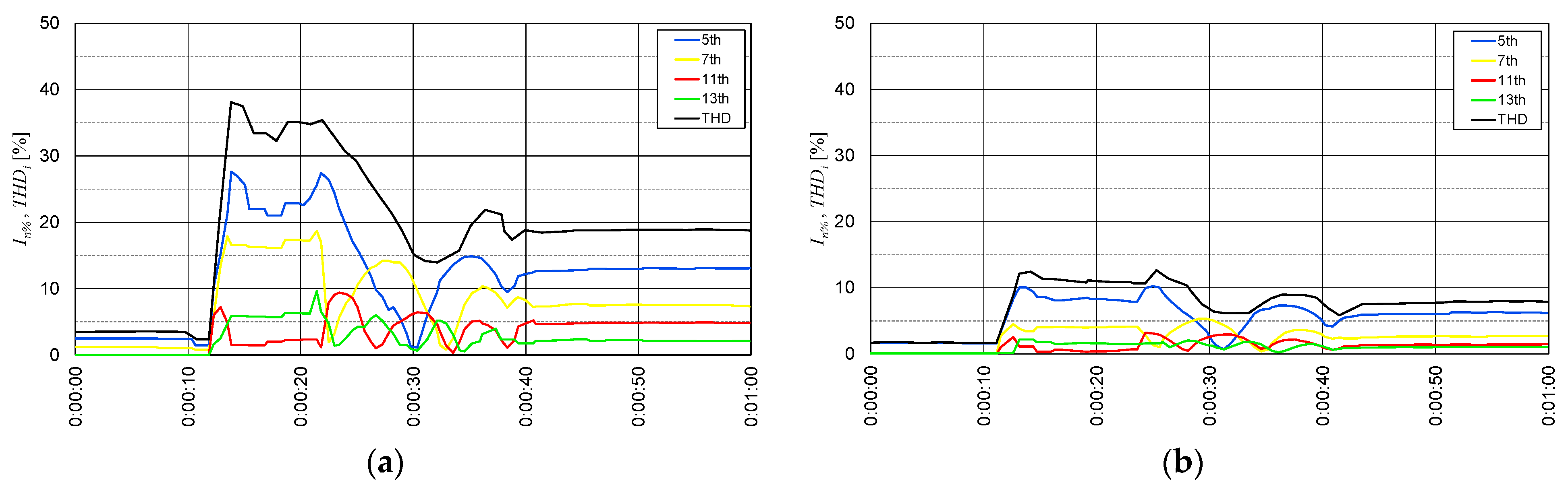
2.2. The Thyristor Hoisting Machine Higher Current Harmonics

The periodic waveform can be expressed as a Fourier series of the form
x ( t ) = a 0 2 + n = 1 ( a n cos ( 2 n π T t ) + b n sin ( 2 n π T t ) ) ,
where
a 0 = 1 T T 2 T 2 x ( t ) d t ,
a n = 2 T T 2 T 2 x ( t ) cos ( 2 n π T t ) d t ,
b n = 2 T T 2 T 2 x ( t ) sin ( 2 n π T t ) d t .
Determining the coefficients an and bn based on the shape of the supply currents iY(t) and iΔ(t) of the rectifiers Y and Δ and taking into account that
i ( t ) = υ i ( 1 2 i Y ( t ) + 3 2 i Δ ( t ) ) ,
assuming an inductive type of load, after transformations, the formula for the primary side current of the supply transformer of a 12-pulse rectifier is then obtained as
i ( t ) = 2 I d π υ i n = 1 ( sin ( n π 2 ) sin ( n π 3 ) ( sin ( n ( α Y t ) ) + 2 3 cos ( n π 6 ) sin ( n ( α Δ t ) ) ) ) ,
where
  • i(t)—current of the primary side of the transformer;
  • Id—current in the DC circuit;
  • υi—transformer current ratio;
  • αY, αΔ—firing angles for Y and Δ rectifiers;
  • n—harmonic order.
The component sin ( n π 2 ) in Expression (9) results in no even harmonics in the current supplying the rectifier, and the component sin ( n π 3 ) results in no harmonics divisible by 3. Due to the product of the above expressions, only the following harmonic orders occur
n = 6 h ± 1 ,   where   h = 0 ,   1 ,   2 ,   3   and   n > 0 .
For the present harmonics, considering the values of the expressions sin ( n π 2 ) , sin ( n π 3 ) , and 2 3 cos ( n π 6 ) , the current of the n-th harmonic can be written as
i n ( t ) = 3 I d n π υ i ( sin ( n ( α Δ t ) ) + ( 1 ) h sin ( n ( α Y t ) ) ) .
From Relation (11), it follows that for symmetrical control (αY = αΔ), there are no harmonics for odd h (n = 5, 7, 17, 19, 29, 31 etc.).
The RMS value of the n-th harmonic of the current that supplies the 12-pulse rectifier can be expressed as
I n = 2 2 I d 3 n π υ i sin 2 ( n π 2 ) sin 2 ( n π 3 ) ( 3 cos ( n π 6 ) cos ( n ( α Δ α Y ) ) + cos 2 ( n π 6 ) + 3 4 ) ,
and taking into account (10) as
I n = 3 I d n π υ i 1 + ( 1 ) h cos ( n ( α Δ α Y ) ) .
Equation (13) shows that in the case of symmetrical control, the RMS values of the harmonics that occur are independent of the firing angles of the thyristors of the two 6-pulse rectifiers. Asymmetrical control results in an increase in the current harmonics of the power grid [15,16,23]. Controlled this way, a 12-pulse rectifier generates current harmonics characteristic of both 12-pulse and 6-pulse rectifiers.
The RMS value of the n-th harmonic in asymmetrical control changes with the change in the difference between the angles αY and αΔ, which occurs when the motor supply voltage is changed; that is, when the driving speed of the hoisting machine is changed.
Current harmonic component In% is defined as
I n % = I n I 1 100 % ,
and current THDi (Total Harmonic Distortion) is defined as
T H D i = n = 2 I n 2 I 1 100 % = I 2 I 1 2 I 1 100 % .
Figure 5 shows the theoretical characteristics of higher current harmonics and the current THDi in the supply line of a 12-pulse rectifier with asymmetrical control as a function of the difference of angles αY and αΔ [17,23]. Since the cos function is even, the characteristics shown in Figure 5 are irrelevant to how the firing angle difference is determined: αYαΔ and αΔαY.
Reduction of higher current harmonics generated by the thyristor rectifier of the hoisting machine during the duty cycle with asymmetrical control requires the use of active filters with appropriate dynamics. Such filters should be located as close as possible to the nonlinear loads that are the source of harmonics.

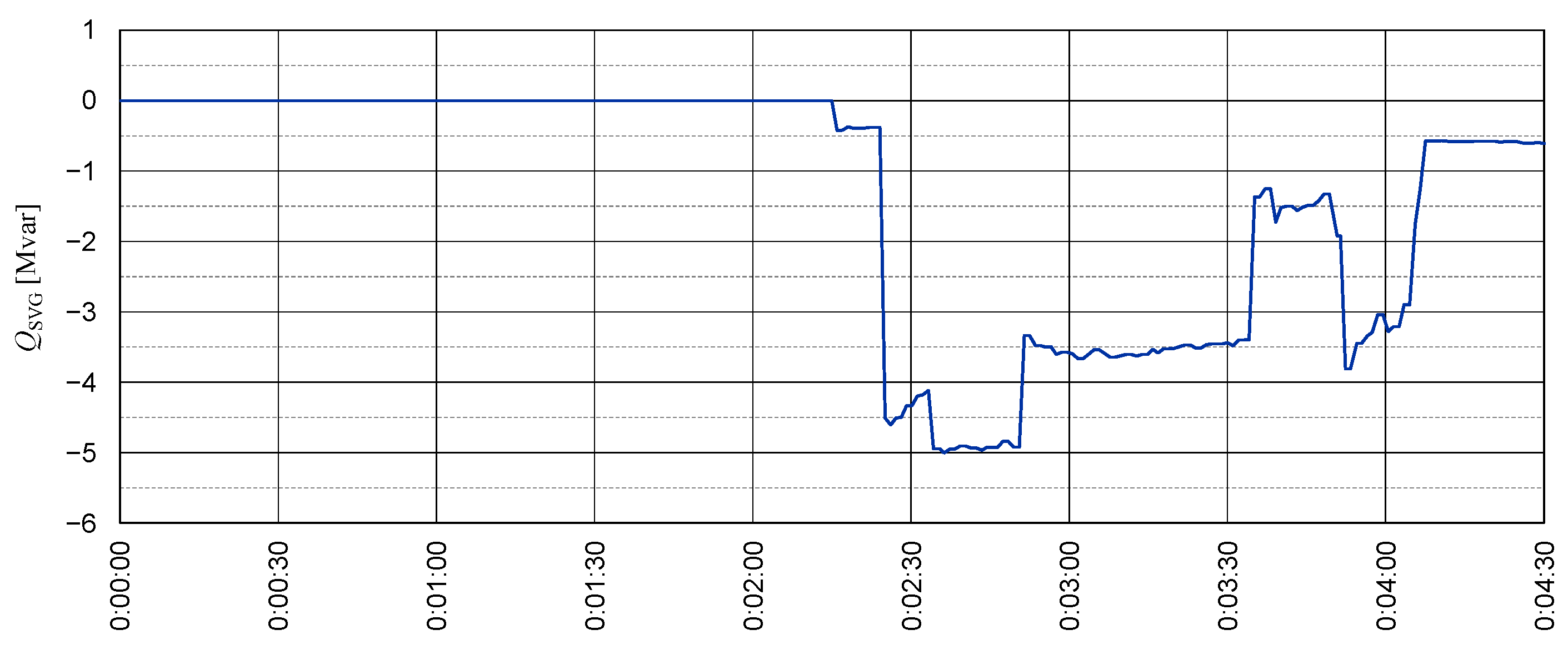
2.3. Static Var Generator

Modern active systems are being used to improve PQ, replacing older solutions based on SVC (Static VAR Compensator) systems, including: typical FC/CSC (Fixed or Contactor Switched Capacitors/Passive filters), advanced TSC (Thyristor Switched Capacitor), TSR (Thyristor Switched Reactor) and TCR (Thyristor Controlled Reactor) [1,2,4,5,19,24,25]. These active systems are, for example, STATCOM (Static Synchronous Compensator), also called SVG (Static Var Generator), which are used for fundamental reactive power compensation, voltage conditioning, and APF (Active Power Filter), designed to eliminate higher current harmonics [4,9,24,26,27,28,29,30].
ASVG (Advanced Static Var Generator) is one of the latest and continuously developing solutions for both reactive power compensation and reduction of higher current harmonics. It combines the functionality of APF and SVG. It is connected to the grid in parallel to nonlinear loads. Electrically, ASVG is a controlled source of injected current (or, in fact, reactive currents for individual harmonics), realized as a voltage source inverter with current feedback. ASVG uses power electronic transistors (usually IGBT) controlled by the PWM method with high switching frequency (depending on the voltage level and the number of levels of the converter topology, the order of several tens of kHz for low voltage, and the order of 500 Hz for medium voltage in a modular multilevel topology) to achieve stepless compensation of reactive currents. This makes it possible to control the amplitude and phase of the output voltage in the AC circuit, thereby generating or drawing the required reactive current.
SVGs are of interest to researchers, both in the direction of modifying topologies and control methods [4,28,31,32,33,34,35,36,37]. They are used in systems requiring voltage stabilization or dynamic reactive power compensation, such as photovoltaic farms, wind farms, arc furnaces, and high-power dynamic drives, such as rolling mills or hoisting machines [29,38,39,40,41,42,43].
ASVGs improve the stability and operating conditions of the power grid by:
  • Reduction (for reduction in a wider range, APF is used) of higher current harmonics in the grid;
  • Reducing (or completely eliminating) the possibility of occurrence of resonance phenomena in the grid for higher harmonics;
  • Stepless regulation of reactive power;
  • Reactive power compensation, both inductive and capacitive loads;
  • Reducing grid voltage fluctuations and light flickering;
  • Reduction of asymmetry (balancing) in multiphase systems;
  • Support for the power grid in FRT (Fault Ride Through), e.g., LVRT (Low Voltage Ride Through) or O(H)VRT (Over Voltage or High Voltage Ride Through).
In typical applications, ASVG compensates for the fundamental reactive power and the higher current harmonics based on the feedback from the point of connection of the device to the grid, usually near the nonlinear load [4]. ASVG manufacturers often offer the ability to customize the control algorithm. Appropriate modification of the ASVG control strategy allows compensation of the higher current harmonics based on feedback from its connection point, and, at the same time, control of the fundamental reactive power based on feedback from another point of the grid, e.g., the plant’s PCC. This solution allows the ASVG to be used in the reactive power automatic compensation system of the entire plant. Currently, thanks to the use of the MMC (Modular Multilevel Converter) topology [28,32,37,44], ASVG systems are built to operate directly connected to the MV grid, without a step-up transformer. Such a system has the ability to generate a smooth output current with very low higher harmonics. This modular topology provides the opportunity to increase reliability by remaining operational even in the event of a single module (cell) failure.

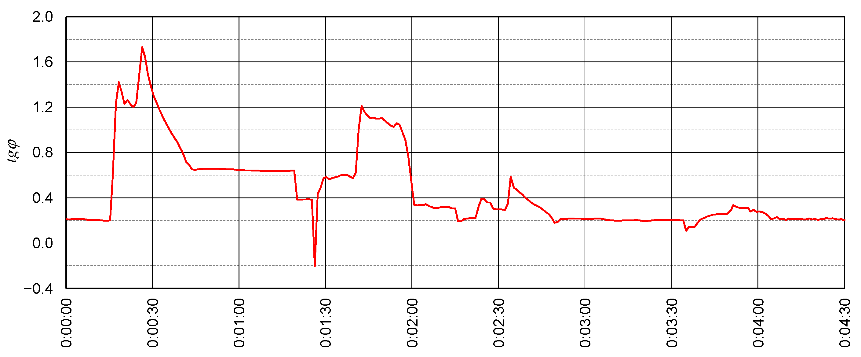
2.4. Reactive Power Automatic Compensation System

In the case of variable active and reactive power loads resulting from the plant’s production cycles, PQ problems can be solved by an automatic real-time tracking reactive power compensation system that allows each PCC to compensate independently and use available reactive power sources in the power grid for this purpose. The idea of a reactive power automatic compensation system implemented in a mine in Poland is presented in Figure 6.
The main controller measures the instantaneous values of active and reactive power at the plant’s PCC, identifies the current configuration of the plant’s internal distribution grid, and decides on the distribution of the currently required reactive power to individual controlled reactive power sources available in the plant’s internal grid. Due to knowledge of the actual configuration of the plant distribution grid, identified by the status of the switches of the distribution switchgears, compensation is performed independently for each PCC without the need to involve technical staff when reconfiguring connections in the distribution grid.
The reactive power automatic compensation system aims to maintain the power coefficient tg φ at the plant’s PCC within the specified range, defined as
t g φ = P Q ,
where
  • tg φ—power coefficient;
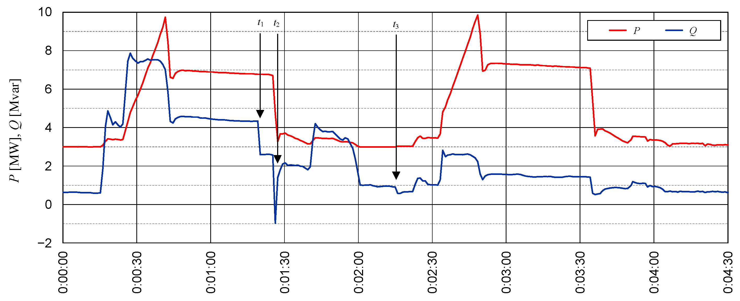
  • P—actual fundamental active power at the plant PCC;
  • Q—actual fundamental reactive power at the plant PCC.
The task of the local controllers is to generate the set value of reactive power in the available compensators, taking into account the operational limitations of the devices used, and to send information about the operating status of the compensators to the main controller.
The control algorithm of the main controller, based on measurements at the plant’s PCC, determines the actual required change in the fundamental reactive power to compensate the PCC, according to the equation
Δ Q z = P t g φ z Q ,
where
  • ΔQz—required change in the fundamental reactive power at the plant PCC;
  • tg φz—set value of power coefficient at the plant PCC.
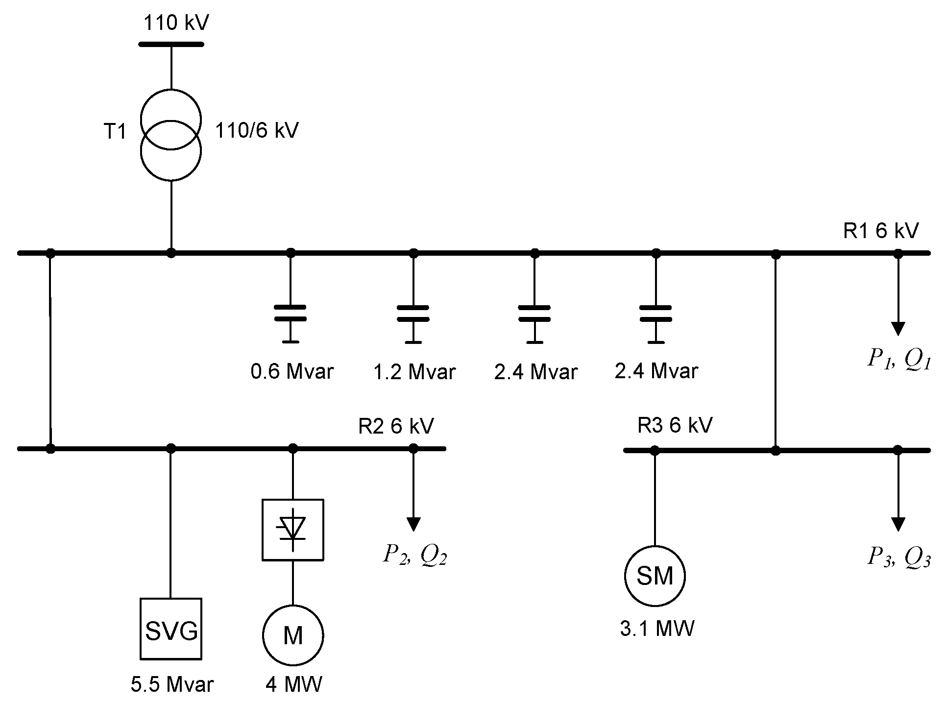
In the next step, the total reactive power Qz, that must be produced by the n available compensators is determined according to the relationship
Q z = Δ Q z + i = 1 n Q i ,
where Qi is the actual fundamental reactive power of the i-th compensator, and the required fundamental reactive power is distributed to individual compensators according to the selected criterion. The simplest criterion for the distribution of reactive power, which does not take into account the parameters of the power cables, is proportional division according to the relationship
Q z i = Q z n
where Qzi is the set value of the fundamental reactive power of the i-th compensator.
If the setpoint value of reactive power cannot be obtained by a given compensating device (e.g., limitation of the reactive power of a synchronous motor related to the active power load), such information is sent to the main controller and the required reactive power is redistributed to the remaining compensators, taking into account the limitations reported by local controllers of the compensators.
The compensation algorithm allows for the reactive power compensation of the fundamental current and voltage at the plant PCC.
The CSC-based system allows for the reactive power compensation in a discrete manner by toggling sections of the power capacitor banks. The ability to turn their particular sections back on after disconnection is limited by the time required to discharge the energy stored in the capacitors [3]. Synchronous motors with controlled excitation currents perform the function of stepless sources of reactive power. However, such control is characterized by poor dynamics, and due to the priority of ensuring safe operation of the drive system, the regulation range is significantly limited and depends on the actual active power load. In order to compensate dynamically changing reactive power in the grid and reduce higher current harmonics, it is possible to include a local ASVG in the reactive power automatic compensation system.

2.5. Case Study

The purpose of the study was to verify the possibility of improving PQ by incorporating ASVG into a reactive power automatic compensation system. The ASVG was already installed, and the authors had no influence on the choice of its parameters and location [45,46,47]. The novelty proposed by the authors was its integration with the reactive power automatic compensation system. Figure 7 shows a simplified diagram of part of the mine distribution power grid under consideration, the valid configuration during the measurements. The ASVG was installed in the R2 substation, from which the thyristor hoisting machine is supplied. The hoisting machine is driven by a 4 MW DC motor powered by a 12-pulse thyristor rectifier.
The main controller of the reactive power automatic compensation system controls the switching of the four capacitor banks in the R1 central distribution substation and the reactive power of the synchronous motor drive of the mine’s underground ventilation fan in the R3 substation with a capacity of 3.1 MW. The fan drive’s synchronous motor excitation current control system is equipped with a microprocessor reactive power controller.
The ASVG is used for local reactive power compensation of the hoisting machine. In addition, the ASVG is used to reduce the higher current harmonics coming from the 12-pulse thyristor hoisting machine supplied from the R2 substation. The basic parameters of the MMC ASVG are presented in Table 1.
The modification of the ASVG control strategy compared to typical applications, apart from reducing the higher current harmonics generated by the thyristor rectifier powering the hoisting machine, allows the fundamental reactive power to be generated independently of the power coefficient tg φ at the point of connection of the ASVG to the grid. Depending on the actual value of the power coefficient tg φ at the plant PCC, the main controller sends the ASVG the appropriate set value of the fundamental reactive power necessary to obtain (together with other compensators) the required tg φ. The ability of the ASVG to generate the current of fundamental and higher harmonics is limited by its rated power. To ensure that there was adequate power reserve to compensate for the higher current harmonics of the hoisting machine thyristor rectifier, the maximum fundamental reactive power setpoint possible to be set by the main controller to the ASVG was limited by the main controller algorithm to a value for which the expected ASVG current would not exceed 450 A.
All measurements presented in this article were recorded by the main controller of the reactive power automatic compensation system. Communication with the different components of the system, and in the case of various parameter readings from some devices, required additional queries to obtain measurement values. For this reason, the measurement points were recorded with a rather limited frequency and were not perfectly synchronized in time. However, characteristic waveforms shapes can be observed, illustrating the operation of the system.

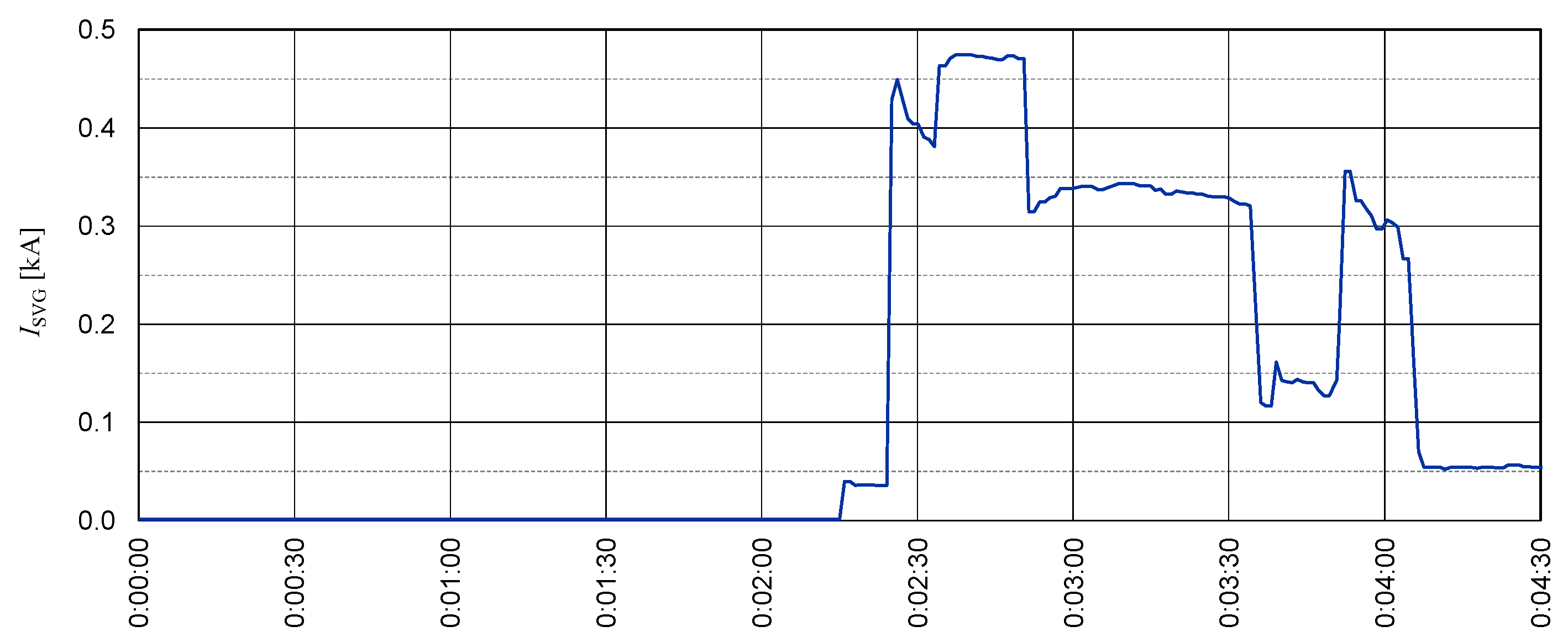
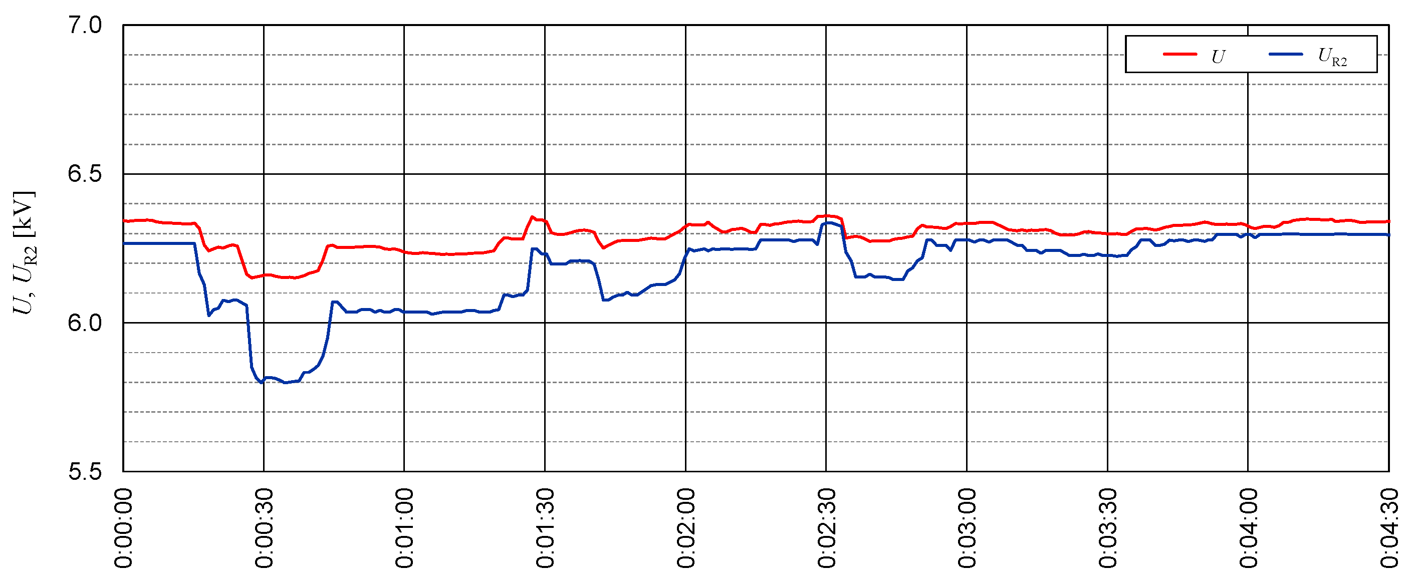
3. Results and Discussion

The timeline in the figures in this chapter is expressed in the format h:mm:ss.
Figure 8 shows the measured current THDi and the selected higher current harmonics on the secondary side of the 110/6 kV power supply transformer in the R1 central distribution substation during the acceleration of the hoisting machine with the inactive and active operation of the ASVG device.
Comparing the waveforms presented in Figure 8a,b, it can be seen that the ASVG does not completely eliminate the higher current harmonics generated by the hoisting machine, but significantly reduces them. It can be seen that for the operation of the hoisting machine without the ASVG, the harmonics in the R1 central distribution substation are lower than the theoretical values generated by the 12-pulse rectifier. It should also be noted that the content of higher current harmonics of the T1 transformer that supplies the R1 central distribution substation is due not only to the operation of the hoisting machine in the R2 substation, but also to the operation of the other loads shown in Figure 7 as equivalent loads in the R1 and R3 substations. The ASVG current feedback is taken from the R2 substation feeder line, so it does not include harmonics generated outside the R2 substation. However, as can be seen in Figure 8, the main source of higher current harmonics in the grid is the hoisting machine.
Figure 9 shows the active and reactive power waveforms and Figure 10 shows the waveforms of the power coefficient tg φ at the plant PCC (secondary side of T1 transformer in the R1 central distribution substation) during two duty cycles of the hoisting machine: without the ASVG and with the ASVG in operation. The first duty cycle was carried out without the ASVG. The activation of the ASVG took place while the hoisting machine was stopped between duty cycles at the time point marked as t3 in Figure 9.
As can be seen in Figure 10, while the hoisting machine is stopped, the reactive power automatic compensation system maintains the power coefficient tg φ at the required value of 0.2. Changes in active and reactive power due to the acceleration of the hoisting machine result in a significant increase in the power coefficient tg φ beyond the allowed range. The dynamics and limited reactive power control range of the synchronous fan drive motor do not allow the plant PCC to be compensated for.
To bring the power coefficient tg φ into the acceptable range, the reactive power automatic compensation system switches on capacitor battery sections of 0.6 Mvar and 1.2 Mvar in the R1 central distribution substation at the time point marked as t1 in Figure 11. However, it should be noted that the ability to switch on individual sections of the capacitor bank, due to time constraints, may not be available for every duty cycle of the hoisting machine.
The deceleration of the hoisting machine causes a decrease in the reactive inductive power. This results in temporary overcompensation; that is, temporary consumption of reactive capacitive power from the DSO grid. The detection of such a state by the reactive power automatic compensation system results in the section of the capacitor bank with a capacity of 2.4 Mvar in the R1 central distribution substation being switched off at the time point marked as t2 in Figure 9. This situation, however, causes the power coefficient tg φ to rise again above the acceptable range of 0 ÷ 0.4.
At the time point marked as t3 in Figure 9, activation of ASVG takes place. The ASVG fundamental reactive power setpoint is determined by the main controller of the reactive power automatic compensation system. While the hoisting machine is stopped, the power coefficient tg φ at the plant PCC is brought to the setpoint value of 0.2.
The second duty cycle of the hoisting machine is characterized by a significant reduction in the variation of the power coefficient tg φ at the plant PCC due to the operation of the ASVG on the basis of the setpoint from the main controller of the reactive power automatic compensation system. In this case, the compensation of the T1 transformer in the R1 central distribution substation is mainly implemented by changing the reactive power of the ASVG, without switching the capacitor bank by the main controller of the reactive power automatic compensation system.
Figure 11 shows the waveforms of active and reactive power in the R2 substation feeder line during the considered duty cycles of the hoisting machine without and with ASVG in operation.
As can be seen in Figure 11, while the hoisting machine is stopped, with the ASVG in operation, the reactive power of the R2 substation is different from 0, as a result of the current reactive power demand in the plant PCC. The change in reactive power of the R2 substation in the second duty cycle of the hoisting machine results from the reactive power generated by the ASVG.
Figure 12 shows the reactive power and Figure 13 shows the current of the ASVG during the duty cycles of the hoisting machine without and with ASVG in operation.
Figure 13 shows that in the presented solution, the ASVG current limitation is not implemented in the device itself, but results from the value of the fundamental reactive power set by the main controller of the reactive power automatic compensation system. Slight overruns of the limit value result from local compensation by the ASVG of higher current harmonics generated by the hoisting machine, which are not taken into account by the main controller of the reactive power automatic compensation system of the T1 transformer in the R1 central distribution substation.
The compensation of the fundamental reactive power by the ASVG also makes it possible to reduce the current in the R2 substation feeder line and the voltage fluctuations in the grid caused by the operation of the hoisting machine. Figure 14 shows the current waveforms on the secondary side of the T1 transformer in the R1 central distribution substation and in the feeder line of the R2 substation, while Figure 15 shows the voltage waveforms on the busbars of the R1 and R2 substations during the duty cycles of the hoisting machine without and with the ASVG in operation.
As can be seen in Figure 15, the reduction in reactive power in the R2 substation feeder line during the hoisting machine duty cycle with activated ASVG contributes to a significant reduction in the voltage fluctuations caused by the machine.

4. Summary and Conclusions

In order to improve PQ in the grid with thyristor hoisting machines, ASVG devices are being increasingly used. As shown in this article, these devices allow, in practice, for reactive power compensation and a significant reduction of higher current harmonics, and at the same time, they can also be used in reactive power automatic compensation systems.
Typically, the ASVG relies on local feedback from either the hoisting machine feeder line or the machine substation feeder line to reduce higher current harmonics or reactive power surges resulting from the operation of the machine. The innovation in the presented solution is the additional control loop from the main controller of the automatic reactive power compensation system of the mine to control the operation of the ASVG.
As proven in this article, our solution enables the ASVG, along with capacitor banks and synchronous motors, to generate the appropriate fundamental reactive power for PCC compensation regardless of the power factor at the ASVG’s point of connection. It also reduces the number of capacitor bank switching. ASVG responds to short-term dynamic changes in reactive power and the capacitors to long-term changes associated with the duty cycle of other facilities in the plant. At the same time, the local feedback allows the ASVG to reduce the higher current harmonics at the supply point.
The ability of ASVG manufacturers to adapt their control algorithms enables the implementation of these devices in non-standard solutions, tailored to customer requirements and specific power grid operating conditions.
The system described in the article was successfully implemented in one of the underground mines in Poland.

Author Contributions

Conceptualization, M.H. and A.L.; methodology, M.H. and A.L.; software, M.H.; validation, M.H. and A.L.; formal analysis, M.H. and A.L.; investigation, M.H. and A.L.; writing—original draft preparation, M.H. and A.L.; writing—review and editing, M.H. and A.L.; visualization, M.H.; supervision, M.H. and A.L. All authors have read and agreed to the published version of the manuscript.

Funding

This research received no external funding.

Data Availability Statement

Data are included in the article; further inquiries may be directed to the corresponding authors.

Conflicts of Interest

The authors declare no conflicts of interest.

References

  1. Motlanthe, N.; Muremi, L. Application of static var compensator with harmonic filters in the heavy industry. In Proceedings of the 2019 Southern African Universities Power Engineering Conference/Robotics and Mechatronics/Pattern Recognition Association of South Africa (SAUPEC/RobMech/PRASA), Bloemfontein, South Africa, 28–30 January 2019; pp. 235–240. [Google Scholar]
  2. Roos, F.; Bansal, R.C. Reactive power and harmonic compensation: A case study for the coal-mining industry. J. Energy S. Afr. 2019, 30, 34–48. [Google Scholar] [CrossRef]
  3. Kgori, P.; Okojie, D.E.; Akuru, U.B. Design and Analysis of a Proposed Multistage Capacitor Bank Compensation Scheme. In Proceedings of the 2022 IEEE PES/IAS PowerAfrica, Kigali, Rwanda, 22–26 August 2022; pp. 1–5. [Google Scholar]
  4. Dixon, J.; Moran, L.; Rodriguez, J.; Domke, R. Reactive Power Compensation Technologies: State-of-the-Art Review. Proc. IEEE 2005, 93, 2144–2164. [Google Scholar] [CrossRef]
  5. Aviña-Corral, V.; Rangel-Magdaleno, J.; Hernandez-Perez, J. 63-Level Asymmetric Capacitor an Inductor Bank without Discharge Resistors and Reduced Transients. In Proceedings of the 2023 IEEE International Autumn Meeting on Power, Electronics and Computing (ROPEC), Ixtapa, Mexico, 18–20 October 2023; pp. 1–6. [Google Scholar]
  6. Varetsky, Y.; Hanzelka, Z. Filter characteristics in a DC drive power supply system. In Proceedings of the 2008 13th International Conference on Harmonics and Quality of Power, Woolongon, NSW, Australia, 28 September–1 October 2008; pp. 1–6. [Google Scholar]
  7. Jiangzi, M.L. Measure and Suppression of Harmonic Currents for Heavy-Duty Hoisting Machines. In Proceedings of the 2005 IEEE/PES Transmission & Distribution Conference & Exposition: Asia and Pacific, Dalian, China, 18 August 2005; pp. 1–4. [Google Scholar]
  8. Pravitasari, D.; Firmansyah, E.; Haryono, T. Harmonic current elimination in industrial power systems. In Proceedings of the 2015 2nd International Conference on Information Technology, Computer, and Electrical Engineering (ICITACEE), Semarang, Indonesia, 16–18 October 2015; pp. 358–362. [Google Scholar]
  9. Li, D.; Wang, T.; Pan, W.; Ding, X.; Gong, J. A comprehensive review of improving power quality using active power filters. Electr. Power Syst. Res. 2021, 199, 107389. [Google Scholar] [CrossRef]
  10. Habrych, M.; Wisniewski, G.; Miedzinski, B.; Wosik, J.; Kozlowski, A. Power loss due to high harmonics in power transformer when use for dc drive of hoisting machines. In Proceedings of the 2014 International Conference on Information Science, Electronics and Electrical Engineering, Sapporo, Japan, 26–28 April 2014; pp. 2065–2070. [Google Scholar]
  11. Semenov, A.S. Analyzing Impacts of Higher Harmonics on Electricity Quality Parameters at Mining Facilities. In Proceedings of the 2024 International Conference on Industrial Engineering, Applications and Manufacturing (ICIEAM), Sochi, Russia, 20–24 May 2024; pp. 321–325. [Google Scholar]
  12. Bebikhov, Y.V.; Egorov, A.N.; Semenov, A.S. How Higher Harmonics Affect the Electrical Facilities in Mining Power Systems. In Proceedings of the 2020 International Conference on Industrial Engineering, Applications and Manufacturing (ICIEAM), Sochi, Russia, 18–22 May 2020; pp. 1–7. [Google Scholar]
  13. IEEE Std 519-2022 (Revision of IEEE Std 519-2014); IEEE Standard for Harmonic Control in Electric Power Systems. IEEE: Piscataway, NJ, USA, 2022.
  14. EN 50160:2023-10; Voltage Characteristics of Electricity Supplied by Public Distribution Networks. CENELEC: Brussels, Belgium, 2023.
  15. Siostrzonek, T.; Chmielowiec, K.; Piątek, K.; Dutka, M.; Firlit, A. The use of multi-pulse systems in the power supply of hoisting machine drives to improve voltage parameters in mining plants. In Proceedings of the 2020 12th International Conference and Exhibition on Electrical Power Quality and Utilisation (EPQU), Cracow, Poland, 14–15 September 2020; pp. 1–6. [Google Scholar]
  16. Hyla, M. Reactive power compensation in a 6 kV power grid supplying a 12-pulse thyristor hoisting machine. Prz. Elektrotech. 2022, 98, 55–63. [Google Scholar] [CrossRef]
  17. Ahsan, F.M.; Chatterjee, J.K.; Das, A. Operation of a 12-pulse converter in closed loop for controlled P-Q operation. In Proceedings of the 2006 International Conference on Power Electronic, Drives and Energy Systems, New Delhi, India, 12–15 December 2006; pp. 1–6. [Google Scholar]
  18. Das, A.; Chatterjee, J.K.; Gaja, A.K. Asymmetrical firing of 12-pulse converter for controlled P-Q operation using PIC microcontroller. In Proceedings of the 2006 IEEE Power India Conference, New Delhi, India, 10–12 April 2006. [Google Scholar]
  19. Hamad, M.S.; Masoud, M.I.; Finney, S.J.; Williams, B.W. Performance analysis of medium voltage series connected 12-pulse current source controlled rectifier using static VAR compensator. In Proceedings of the 2008 IEEE International Symposium on Industrial Electronics, Cambridge, UK, 30 June–2 July 2008; pp. 282–286. [Google Scholar]
  20. Modi, P.S.; Joshi, S.K. New combined Hybrid active filter for twelve pulse converter operating under asymmetrical operation. In Proceedings of the Australasian Universities Power Engineering Conference AUPEC, Brisbane, QLD, Australia, 25–28 September 2011; pp. 1–6. [Google Scholar]
  21. Modi, P.S.; Joshi, S.K. Effect of source inductance on controlled var operation of 12-pulse converter. In Proceedings of the 2009 International Conference on Control, Automation, Communication and Energy Conservation, Perundurai, India, 4–6 June 2009; pp. 1–7. [Google Scholar]
  22. Hamad, M.S.; Masoud, M.I.; Williams, B.W. Medium-Voltage 12-Pulse Converter: Output Voltage Harmonic Compensation Using a Series APF. IEEE Trans. Ind. Electron. 2014, 61, 43–52. [Google Scholar] [CrossRef]
  23. Hamad, M.S.; Masoud, M.I.; Massoud, A.M.; Finney, S.J.; Williams, B.W. A new power locus for the p-q operation of series connected 12-pulse current source controlled converters. In Proceedings of the 2008 IEEE Power Electronics Specialists Conference, Rhodes, Greece, 15–19 June 2008; pp. 2264–2270. [Google Scholar]
  24. Kowalak, R. Modelling of Power Electronic Compensators for the Analysis of Power System Operation. Acta Energ. Power Eng. Q. 2013, 17, 48–55. [Google Scholar] [CrossRef]
  25. Igbinovia, F.O.; Fandi, G.; Švec, J.; Müller, Z.; Tlusty, J. Comparative review of reactive power compensation technologies. In Proceedings of the 16th International Scientific Conference on Electric Power Engineering EPE, Kouty and Desnou, Czech Republic, 20–22 May 2015; pp. 2–7. [Google Scholar]
  26. Buła, D.; Michalak, J.; Zygmanowski, M.; Adrikowski, T.; Jarek, G.; Jeleń, M. Control Strategy of 1 kV Hybrid Active Power Filter for Mining Applications. Energies 2021, 14, 4994. [Google Scholar] [CrossRef]
  27. Buła, D.; Jarek, G.; Michalak, J.; Zygmanowski, M. Control Method of Four Wire Active Power Filter Based on Three-Phase Neutral Point Clamped T-Type Converter. Energies 2021, 14, 8427. [Google Scholar] [CrossRef]
  28. Li, Y.; Wang, C.; Zhao, X.; Zhang, K. Research of Mining STATCOM Based on Hybrid Multilevel H-bridge Inverter. Energy Power Eng. 2013, 5, 636–641. [Google Scholar] [CrossRef]
  29. Sun, R.; Qiu, H.; Chen, B.; Yuan, X.; Luo, S.; Gu, W. Voltage sag improvement using DVR and SVG in power systems. In Proceedings of the 2016 China International Conference on Electricity Distribution (CICED), Xi’an, China, 10–13 August 2016; pp. 1–5. [Google Scholar]
  30. Ma, Y.; Huang, A.; Zhou, X. A review of STATCOM on the electric power system. In Proceedings of the 2015 IEEE International Conference on Mechatronics and Automation (ICMA), Beijing, China, 2–5 August 2015; pp. 162–167. [Google Scholar]
  31. Ren, L.; Wang, F.; Shi, Y.; Gao, L. Coupling Effect Analysis and Design Principle of Repetitive Control Based Hybrid Controller for SVG with Enhanced Harmonic Current Mitigation. IEEE J. Emerg. Sel. Top. Power Electron. 2022, 10, 5659–5669. [Google Scholar] [CrossRef]
  32. Peng, F.Z.; Lai, J.-S. Dynamic performance and control of a static VAr generator using cascade multilevel inverters. IEEE Trans. Ind. Appl. 1997, 33, 748–755. [Google Scholar] [CrossRef]
  33. Cheng, H.; Yin, X.; Wang, Z.; Chen, S. Control Analysis and Stability for Static VAR Generator. IFAC Proc. Vol. 2003, 36, 1025–1030. [Google Scholar] [CrossRef]
  34. Luo, R.; He, Y.; Tu, Y.; Chen, X.; Liu, J. Research on the Unbalanced Compensation Range of Delta-connected Cascaded H-bridge Multilevel SVG. In Proceedings of the 2018 International Power Electronics Conference (IPEC-Niigata 2018-ECCE Asia), Niigata, Japan, 20–24 May 2018; pp. 3439–3444. [Google Scholar]
  35. Fujun, M.; An, L.; Qiaopo, X.; Zhixing, H.; Qianming, X. Derivation of zero-sequence circulating current and the compensation of delta-connected static var generators for unbalanced load. IET Power Electron. 2016, 9, 576–588. [Google Scholar] [CrossRef]
  36. Yu, Y.; Xu, D.; Wu, J.; Xu, R.; Yu, Y.; Yang, R.; Yan, J. Research and design on multi-target current tracking control strategy of cascaded H-bridge static var generator. In Proceedings of the 2014 17th International Conference on Electrical Machines and Systems (ICEMS), Hangzhou, China, 22–25 October 2014; pp. 2471–2477. [Google Scholar]
  37. Peng, F.Z.; Lai, J.-S.; McKeever, J.W.; VanCoevering, J. A multilevel voltage-source inverter with separate DC sources for static VAr generation. IEEE Trans. Ind. Appl. 1996, 32, 1130–1138. [Google Scholar] [CrossRef]
  38. Yu, K.; Shi, Z.; Zang, Y.; Lu, Q.; Xiang, Y.; Lai, H. Reactive Voltage Control in Photovoltaic Power Stations Considering Source-Load Uncertainty. In Proceedings of the 2024 IEEE 6th Advanced Information Management, Communicates, Electronic and Automation Control Conference (IMCEC), Chongqing, China, 24–26 May 2024; pp. 1934–1938. [Google Scholar]
  39. Su, S.; Li, P.; Yan, Y.-t.; Yang-Yang; Gao, F.; Xue, A.-c. Analysis of the impact of SVG on the voltage stability of an actual wind farm. In Proceedings of the International Conference on Renewable Power Generation (RPG 2015), Beijing, China, 17–18 October 2015; pp. 1–4. [Google Scholar]
  40. Zhou, Z.; Mastoi, M.S.; Wang, D.; Haris, M. Control strategy of DFIG and SVG cooperating to regulate grid voltage of wind power integration point. Electr. Power Syst. Res. 2023, 214, 108862. [Google Scholar] [CrossRef]
  41. Wei, Z.; Runqing, B.; Yong, Z.; Chen, L. Research on application of SVG for reactive power control in wind farm. In Proceedings of the 2012 Power Engineering and Automation Conference, Wuhan, China, 18–20 September 2012; pp. 1–3. [Google Scholar]
  42. Kashani, M.G.; Babaei, S.; Bhattacharya, S. SVC and STATCOM application in Electric Arc Furnace efficiency improvement. In Proceedings of the 2013 4th IEEE International Symposium on Power Electronics for Distributed Generation Systems (PEDG), Rogers, AR, USA, 8–11 July 2013; pp. 1–7. [Google Scholar]
  43. Abdelmohsen, A.M.; Hebala, A.M.; Hamad, M.S. Comparative Study of SVC and STATCOM Performance on Reactive Power Compensation in Hot Strip Mill. In Proceedings of the 2023 IEEE Conference on Power Electronics and Renewable Energy (CPERE), Luxor, Egypt, 19–21 February 2023; pp. 1–7. [Google Scholar]
  44. Raju, M.N.; Sreedevi, J.; Mandi, R.P.; Meera, K.S. Modular multilevel converters technology: A comprehensive study on its topologies, modelling, control and applications. IET Power Electron. 2019, 12, 149–169. [Google Scholar] [CrossRef]
  45. Tian, S.; Jia, Q.; Xue, S.; Yu, H.; Qu, Z.; Gu, T. Collaborative optimization allocation of VDAPFs and SVGs for simultaneous mitigation of voltage harmonic and deviation in distribution networks. Int. J. Electr. Power Energy Syst. 2020, 120, 106034. [Google Scholar] [CrossRef]
  46. Tian, S.; Jia, Q.; Cui, Y.; Xue, S.; Yu, H.; Liu, W. Multi-objective Collaborative Optimization of VDAPFs and SVGs Allocation Considering MFGCIs Contribution for Voltage Partitioning Mitigation in Distribution Networks. Electr. Power Syst. Res. 2022, 207, 107830. [Google Scholar] [CrossRef]
  47. Wang, D.; Cui, T.; Hu, Z.; Shen, Y. Impacts of SVG Location and Capacity on Voltage Recovery Characteristics in Hunan Network. In Proceedings of the 2019 4th International Conference on Intelligent Green Building and Smart Grid (IGBSG), Yichang, China, 6–9 September 2019; pp. 418–421. [Google Scholar]
Figure 1. A single-cycle speed diagram of the hoisting machine.
Energies 17 03628 g001
Figure 2. Schematic diagram of the 12-pulse rectifier for powering a hoisting machine.
Energies 17 03628 g002
Figure 3. Idea of asymmetrical control of a 12-pulse rectifier.
Energies 17 03628 g003
Figure 4. Active and reactive power of the hoisting machine during the single duty cycle—simulation results: (a) symmetrical firing angle control; (b) asymmetrical firing angle control.
Energies 17 03628 g004
Figure 5. Theoretical higher current harmonics and THDi of the 12-pulse rectifier with asymmetrical control depending on the firing angle difference αY and αΔ.
Energies 17 03628 g005
Figure 6. Reactive power automatic compensation system.
Energies 17 03628 g006
Figure 7. Simplified diagram of the mine distribution power grid: T1—supply power transformer; M—hoisting machine; SVG—ASVG; SM—synchronous motor of the fan drive; P1, Q1, P2, Q2, P3, Q3—equivalent active and reactive power loads of the other powered devices.
Energies 17 03628 g007
Figure 8. Waveforms of current THDi and 5th, 7th, 11th, and 13th current harmonics in the secondary winding of the 110/6 kV supplying transformer in the R1 central distribution substation during the acceleration of the hoisting machine (a) without the ASVG and (b) with the ASVG in operation.
Energies 17 03628 g008
Figure 9. Active power (P) and reactive power (Q) waveforms in the secondary winding of the T1 transformer in the R1 central distribution substation during two duty cycles of the hoisting machine.
Energies 17 03628 g009
Figure 10. Power coefficient (tg φ) waveform in the secondary winding of the T1 transformer in the R1 central distribution substation during two duty cycles of hoisting.
Energies 17 03628 g010
Figure 11. Active power (PR2) and reactive power (QR2) waveforms at the R2 substation feeder line during two duty cycles of the hoisting machine.
Energies 17 03628 g011
Figure 12. Reactive power waveform of the ASVG (QSVG) during two duty cycles of the hoisting machine.
Energies 17 03628 g012
Figure 13. Current waveform of the ASVG (ISVG) during two hoisting machine duty cycles.
Energies 17 03628 g013
Figure 14. Waveforms of currents in the secondary winding of T1 transformer in the R1 central distribution substation (I) and in the feeder line of the R2 substation (IR2) during two duty cycles of the hoisting machine.
Energies 17 03628 g014
Figure 15. Waveforms of voltages on the R1 central distribution substation busbar (U) and the R2 substation busbar (UR2) during two duty cycles of the hoisting machine.
Energies 17 03628 g015
Table 1. ASVG HTSVG-6/5.5-H rated parameters.
ParametersValue
compensator power5.5 Mvar
current RMS530 A
working voltage6 kV
filtering capacity2–25th harmonic
transient response<0.1 ms
complete response<10 ms
efficiency>97%
frequency50 Hz ± 5%
Disclaimer/Publisher’s Note: The statements, opinions and data contained in all publications are solely those of the individual author(s) and contributor(s) and not of MDPI and/or the editor(s). MDPI and/or the editor(s) disclaim responsibility for any injury to people or property resulting from any ideas, methods, instructions or products referred to in the content.

