Review

Convective Heat Transfer in PWR, BWR, CANDU, SMR, and MSR Nuclear Reactors—A Review

by
Daria Sikorska
1,
Julia Brzozowska
1,
Agata Pawełkiewicz
1,
Mateusz Psykała
1,
Przemysław Błasiak
2 and
Piotr Kolasiński
2,*
1
Faculty of Mechanical and Power Engineering, Wrocław University of Science and Technology, 50-370 Wrocław, Poland
2
Department of Thermodynamics and Renewable Sources of Energy, Faculty of Mechanical and Power Engineering, Wrocław University of Science and Technology, 50-370 Wrocław, Poland
*
Author to whom correspondence should be addressed.
Energies 2024, 17(15), 3652; https://doi.org/10.3390/en17153652
Submission received: 20 June 2024 / Revised: 15 July 2024 / Accepted: 17 July 2024 / Published: 24 July 2024
(This article belongs to the Collection Advances in Heat Transfer Enhancement)

Abstract

:
Nuclear reactors are very complex units in which many physical processes occur simultaneously. Efficient heat removal from the reactor core is the most important of these processes. Heat is removed from the reactor core via heat conduction, radiation, and convection. Thus, convective heat transfer and its conditions play a crucial role in the operation and safety of nuclear reactors. Convective heat transfer in nuclear reactors is a very complex process, which is dependent on many conditions and is usually described by different correlations which combine together the most important criteria numbers, such as the Nusselt, Reynolds, and Prandtl numbers. The applicability of different correlations is limited by the conditions of heat transfer in nuclear reactors. The selection of the proper correlation is very important from the reactor design accuracy and safety points of view. The objective of this novel review is to conduct a comprehensive analysis of the models and correlations which may be applied for convective heat transfer description and modeling in various types of nuclear reactors. The authors review the most important research papers related to convective heat transfer correlations which were obtained by experimental or numerical research and applied calculations and heat transfer modeling in nuclear reactors. Special focus is placed on pressurized water reactors (PWRs), boiling water reactors (BWRs), CANDU reactors, small modular reactors (SMRs), and molten salt reactors (MSRs). For each type of studied reactor, the correlations are grouped and presented in tables with their application ranges and limitations. The review results give insights into the main research directions related to convective heat transfer in nuclear reactors and set a compendium of the correlations that can be applied by engineers and scientists focused on heat transfer in nuclear reactors. Prospective research directions are also identified and suggested to address the ongoing challenges in the heat transfer modeling of present and next-generation nuclear reactors.

1. Introduction

Nuclear power plants are one of the most important power engineering technologies. Thanks to their application, it is possible to generate electricity at a large scale and with high efficiency. Their application contributes to the limiting of flue gas emissions. For this reason, nuclear power plants are considered to be a cleaner power-generation technology when compared, for example, to classically applied coal-fed thermal power stations. One of the most important parts of the nuclear power plant is the nuclear reactor. Nuclear reactors can be classified into main categories, such as pressurized water reactors (PWRs), boiling water reactors (BWRs), liquid metal-cooled fast reactors (LMFRs), gas-cooled reactors (GCRs), molten salt reactors (MSRs), small modular reactors (SMRs), etc. From the design and operation points of view, the nuclear reactor is a very complex thermal unit. It should be designed and operated in a way that enables its safe and long operability. The nuclear reactor’s physical description is complex as many physical processes simultaneously take place in the nuclear reactor core. The most important process is nuclear fission, which takes place in the nuclear fuel and which gives up the energy that is then transferred to the reactor coolant. To ensure the safety of the reactor and the power plant, a high efficiency of released thermal energy transfer is needed; therefore, a special design (featuring a large heat transfer area and specific thermohydraulic shape) of the nuclear reactor core has to be applied. For this reason, a large number of fuel elements are usually used in the nuclear reactor core.
The two main mechanisms of heat transfer in the nuclear reactor are heat conduction and convection. Heat conduction occurs in nuclear fuel elements (i.e., fuel pellets and clad). In many cases, it is assumed that the heat transfer in the gas gap can also be treated as heat conduction due to the lack of gas movement in the gap. From the outer surface of the fuel elements, heat is transferred to the coolant by convection. It is worth noting that convective heat transfer in nuclear reactors is a very complex process, which is dependent on many conditions. In various types of nuclear reactors, the convective heat transfer conditions may differ because they are related to the flow channel geometry, applied coolant, and other conditions. The heat transfer rate, which refers to the heat transferred through convection, is crucial from the reactor operational and safety points of view. The Nusselt number, the value of which is the most important criterion related to convective heat transfer, is usually calculated using correlations specific to selected convective heat transfer phenomena which combine together the most important criteria numbers, such as the Nusselt, Reynolds, and Prandtl numbers. Therefore, different correlations may be applied to the Nusselt number and heat transfer coefficient estimation for different types of nuclear reactors and the selection of the proper correlation is very important from the reactor design accuracy and safety point of view. Intensive development of nuclear reactors has been observed since the early 1950s. The first commercial PWRs and BWRs were implemented in 1957, the first CANDU reactor started operation in 1962, MSRs were developed in the late 1960s, and SMRs were developed in the 2000s. During the reactors’ development, many research works focused on the description of convective heat transfer in these power units. These works proceeded together with reactor design development and gave insights into the flow patterns, heat transfer mechanisms, and thermal–hydraulic phenomena occurring within the reactor core, coolant channels, heat exchangers, and containment systems. Recently developed numerical methods are very important tools which can be applied for the simulation of fluid flow and heat transfer in nuclear reactors.
Recently, there has been increased interest in nuclear power plants observed worldwide. This trend is also visible in the number of articles related to convective heat transfer in nuclear reactors, which have recently been published in different scientific journals. Figure 1 shows this trend based on the results of a search of the Web of Science database for the “convective heat transfer nuclear reactor” keyword. It can be seen that there has been a large increase in the number of articles related to this subject starting from 2008.
In the later part of this article, the authors review the literature related to convective heat transfer correlations, which may be applied for convective heat transfer modeling and calculations in the selected types of nuclear reactors (i.e., PWRs, BWRs, CANDU, SMRs, and MSRs). For each type of reactor studied, the correlations are grouped and presented in tables with their application ranges and limitations.
In Section 2 of the article, a review of convective heat transfer correlations valid for PWRs is presented. In the case of PWRs [1], the high-velocity coolant flow over the external surfaces of fuel rods drives convective heat transfer. In most cases, pressurized water is used as the coolant in these types of reactors, and the classical convective heat transfer correlations can be applied for calculations [2]. However, the literature review results [2,3,4,5,6,7,8,9,10,11,12,13,14,15,16] show that there is increased interest in nanofluid application for heat transfer enhancement in PWRs.
Section 3 reports a review of convective heat transfer correlations valid for BWRs. Due to the evaporation processes in the boiling water reactor core [17], convective heat transfer in BWRs proceeds more intensively compared to other types of nuclear reactors that use water as a coolant. Therefore, in addition to the analyses related to boiling process description using different convective heat transfer correlations [18,19,20,21,22,23,24,25,26,27], many studies related to the safety of BWR reactors under emergency conditions are analyzed in the papers related to convective heat transfer [28,29,30,31,32,33,34,35,36,37].
In Section 4, the review results related to CANDU reactors are presented. In CANDU reactors, a special type of pressure tube is applied [38]. Thus, the convective heat transfer conditions are different from those in other types of nuclear reactors. The literature review shows that the convective heat transfer correlations applied are similar to those used for modeling forced convection during fluid flow inside the tubes [39,40,41,42,43,44,45,46,47,48,49,50,51,52]. For CANDU reactors, additional parameters can be incorporated into the correlations.
Section 5 reviews the correlations used for modeling and calculating convective heat transfer in small modular reactors. SMRs are considered a novel energy technology [53] that could have a significant impact on the nuclear energy market in the future. The correlations used for SMRs are similar to those applied to PWRs but are often modified with additional correction parameters [54,55,56,57,58,59,60,61,62,63,64,65,66,67,68,69,70,71,72,73,74,75,76,77,78].
The final type of nuclear reactor reviewed is MSRs, which are described in Section 6. For these reactors, convective heat transfer occurs in molten salts [79], and the corresponding correlations must include parameters specific to the applied coolant and heat transfer conditions. Therefore, the convective heat transfer correlations for MSRs differ from those used for other types of reactors [80,81,82,83,84,85,86,87,88,89,90,91].
The review provides insight into key research directions related to convective heat transfer in nuclear reactors and serves as a comprehensive resource of correlations for engineers and scientists working on heat transfer in these systems. The applicability and limitations of each correlation were identified based on the reviewed works and their conditions.
The review results highlight the emerging trends and future directions in convective heat transfer research, such as the use of nanofluids as coolants and the simulation of heat transfer during reactor failures and accidents.

2. PWR Reactors

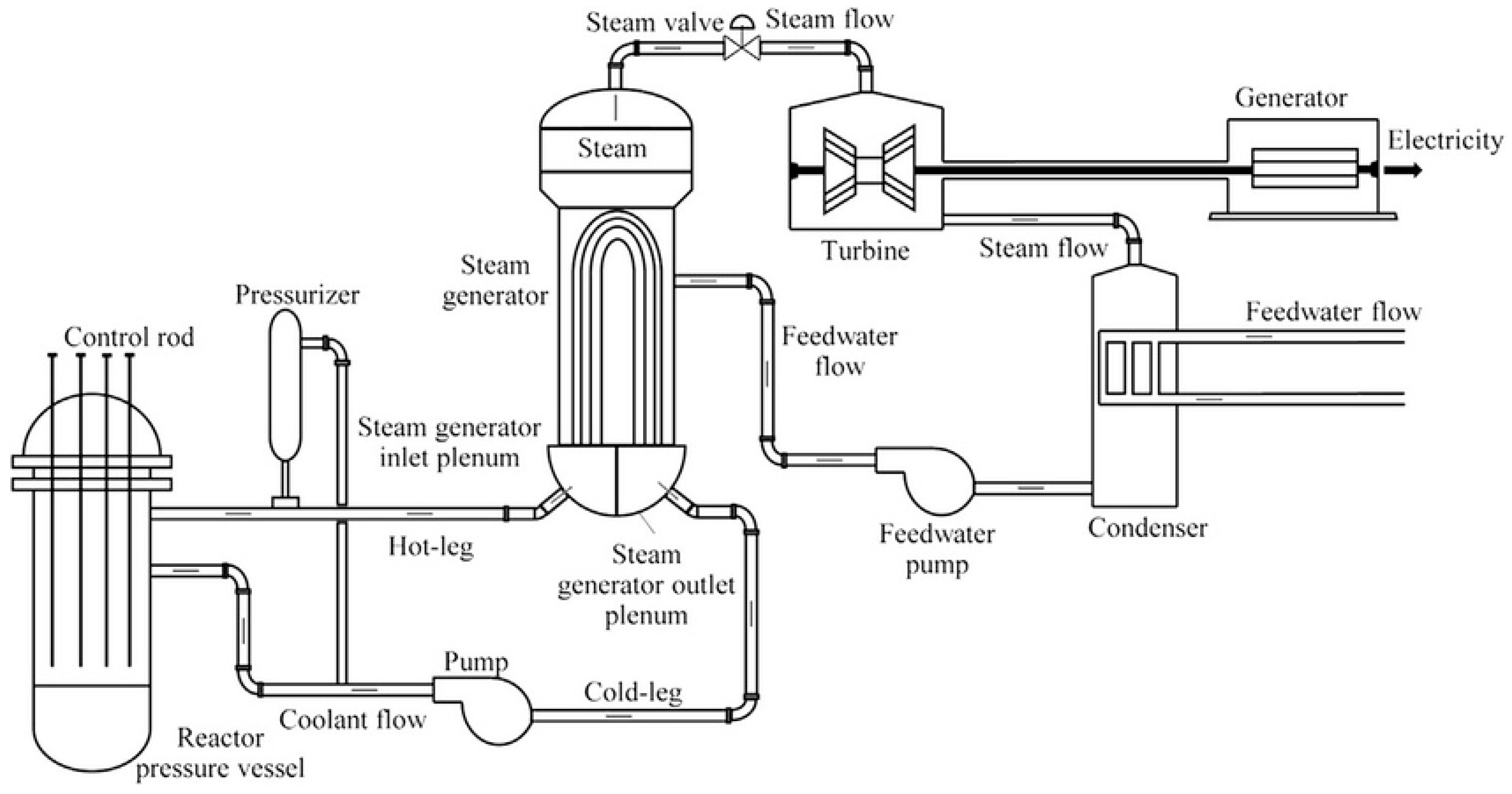
Pressurized water reactors (PWRs) are the most common type of reactor used in power engineering. A PWR has two circuits, as shown in the schematic diagram presented in Figure 2. The circuit on the left is called the primary circuit and is maintained at high pressure (15–16 MPa) to prevent the water from boiling. Therefore, under normal reactor operation, convective heat transfer occurs in the liquid phase of the coolant. Convective heat transfer ensures the efficient removal of heat from the core and its transfer to the steam generators. The heat produced in the core is transferred by conduction from the fuel to the surface of the fuel cladding, and then by convection to the coolant. Typically, in pressurized water reactors, light water is used as the coolant. The reactor pumps force water through the reactor vessel at high velocities, maintaining fully developed turbulent flow conditions within the vessel. The efficiency of convective heat transfer in PWR depends on factors such as the coolant velocity, density, viscosity, thermal conductivity, and the geometry of the fuel rods and flow channels. Heat transfer from the core is a crucial element of PWR safety, as it maintains the temperature distribution in the reactor. Uneven temperature distribution can lead to local issues with fuel integrity. In the case of turbulent flow, the classical Dittus–Boelter correlation can be used to describe convective heat transfer in the coolant of pressurized water reactors [2]. Recent literature shows increased attention to research on the effects of adding nanoparticles to cooling water.
Shamim et al. [2] analyzed the effects of using various concentrations (0.5–3.0%) of water–alumina nanofluid as a coolant on heat transfer and pressure drop under typical PWR operating conditions at different flow rates. Simulations were conducted for a square array subchannel with pitch-to-diameter ratios of 1.25 and 1.35. The results were obtained using pressure loss correlations and conventional single-phase convective heat transfer correlations for fully-developed turbulent flow. The obtained results were then compared with numerical data. The results from standard empirical correlations (i.e., Equation (1) in Table 1) did not match the numerical results, leading to the proposal of a new modified correlation (i.e., Equation (2) in Table 1) for describing convective heat transfer. It was also found that using nanofluid can improve the convective heat transfer coefficient. However, this improvement may come with a larger pressure drop. Both the convective heat transfer coefficient and pressure drop were observed to increase with a higher nanofluid concentration.
Hatami et al. [3] presented an optimized design for the arrangement of fuel rods in a typical PWR, using the turbulent flow of Al2O3–water nanofluid as the coolant. The authors aimed to numerically determine the optimal rod diameter and spacing to maximize heat transfer and achieve the highest possible cooling performance. They used Equation (2) from Table 1 (which is applicable for Reynolds numbers in the range of Re = 104–5·105). The authors indicated that reducing the distance between the rods and the diameter of the rods improves the cooling performance due to a higher Nusselt number. Figure 3 shows the temperature of the nanofluid between the rods in the examined geometries. Using Al2O3 nanofluid increased the Nusselt number by 17%. These results were observed consistently, regardless of whether the Reynolds number was low or high.
Liu et al. [4] investigated how numerical issues affect the results of computational fluid dynamics (CFD) simulations for a PWR 5 × 5 fuel rod bundle model with a spacer assembly. The study found that the shear stress transport (SST) turbulence model provided the most accurate results. All models considered were available in Fluent 12.0 software. The SST model was found to be the most accurate due to its near-wall treatment, which addresses turbulent viscosity in regions with low Reynolds numbers, unlike the standard wall treatment used in other turbulence models. This model accurately predicts the highest Nusselt number near the wall, as confirmed by experimental results.
Ghazanfari et al. [5] analyzed the use of a water–Al2O3 nanofluid mixture at various volume percentages as a coolant for a VVER-1000 (OKB Gidropress, Podolsk, Russia) reactor. Figure 4 compares the axial fuel temperature distribution in the annular fuel for the base fluid (water) and fluids with 10 and 20% of nanoparticles. The results showed that as the concentration of Al2O3 nanoparticles increased, the heat transfer coefficient of the nanofluid improved. This led to a higher coolant temperature and a reduction in the central fuel temperature. It was also noted that the convective heat transfer coefficient is higher for nanofluid compared to water under the same mass flow rate and inlet temperature conditions. Another important conclusion is that the use of nanoparticles allows for a lower coolant flow rate. This means the reactor core can be smaller, potentially reducing the capital cost of the nuclear power plant.
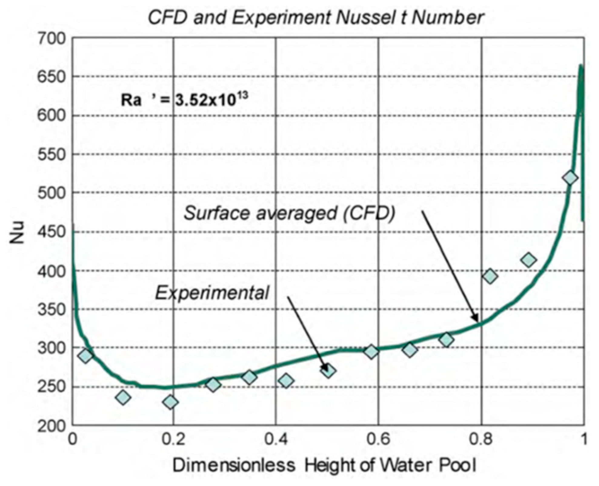
Vieira et al. [6] conducted computational modeling of natural convection at the bottom of a typical PWR pressure vessel following a severe accident. The simulation used a two-dimensional semi-circular slice geometry and the Boussinesq model to account for buoyancy effects in the flow (see Equation (3) in Table 1). The turbulent eddy viscosity is captured using the two-equation k-ω SST model. Theoretical data were calculated using the correlations from Mayinger et al. [7] and Kulacki and Emara [8] (see Equations (4) and (5) in Table 1). Computational calculations were performed for two values of Prandtl numbers (i.e., 6.13 and 7.0) and five values of Rayleigh numbers (i.e., 109, 1010, 1011, 1012, and 1013). A comparison of the obtained calculation results with theoretical data suggests that the average Nusselt numbers on the bottom surfaces, calculated by the simulation, are consistent with the correlation from Mayinger et al. [7]. However, on the upper surfaces, the average Nusselt numbers are consistent with the correlations from Mayinger et al. [7] and Kulacki and Emara [8] only for Ra = 109.
Zhang et al. [9] developed a theoretical model (see Equations (6) and (7) in Table 1) to simulate the 3D transient heating and melting progress of the reactor core following a station blackout accident, based on a 2D heat transfer analysis of each rod. This study examined the Hualong 1 reactor, a 100 MW PWR that utilizes an in-vessel retention (IVR) design. This system features the reactor pressure vessel submerged in a water chamber, which prevents core melt from passing through the lower head of the reactor pressure vessel (RPV) and escaping the containment during a severe incident. The reactor’s initial power is approximately 3150 MW before it is shut down. The convective heat flux on the fuel rod surface initially decreased due to the rapid drop in water level, then increased as the temperature difference between the fuel rod and the vapor grew. As the water evaporated, convection diminished significantly, the convective heat flux on the fuel rod surface decreased, and fuel rods began to melt. In terms of melting, the control rod in the core begins to deteriorate after approximately 500–700 s, while the fuel rods do not start to melt until around 4860 s into the simulation. However, some localized areas begin to melt after 1060 s.
Holloway et al. [10] examined convection for turbulent flow between rod bundles in representative PWR reactors. They used Equations (9) and (10) from Table 1 to study a 5 × 5 square array rod bundle. Air was used as a coolant instead of water to reduce the power required to heat the rods. The study demonstrates that the support grids enhance local heat transfer within the rod bundle. Minimizing the distance between support grids can significantly enhance heat transfer in rod bundles. However, inserting additional support grids also increases pressure loss, so an optimal design must be developed to balance these effects. A correlation (i.e., Equation (10) from Table 1) was developed to enhance the heat transfer downstream of support grid designs.
Liu and Ferng [11] developed a 3D CFD model using the Reynolds stress turbulence model to analyze the thermal–hydraulic characteristics within the fuel rod bundle. They also studied how different types of grids (standard grids with vanes and split-vane pair grids with vanes) affect heat transfer enhancement and turbulent mixing. The authors found that the Nusselt number decreases downstream of the grid, approaching a fully developed value.
This experimental result was confirmed by mathematical calculations using the Yao et al. [12] correlation (i.e., Equation (11) from Table 1) and the CFD model. The obtained results were then compared with the model from Hollaway et al. [13] (see Equation (12) in Table 1). Good agreement was found between the models using a standard grid. However, in models with a split-vane pair grid, a discrepancy in the downstream Nusselt number distribution was observed. This could be improved by using a finer mesh and a low-Reynolds-number turbulence model.
Hollaway et al. [13] examined heat transfer in a rod bundle downstream of the support grids, investigating conditions with and without forced convection for Reynolds numbers ranging from 28,000 to 42,000. Additionally, two flow-enhancing features were explored: support grids with split-vane pairs and support grids with disk blockage. A Nusselt number correlation was developed for the support grids with disk blockage, which was found to provide the greatest heat transfer among all the cases examined.
Hadad et al. [14] examined the effect of adding Al2O3 nanofluid to the VVER-1000 core using a CFD model. Numerical calculations were performed using both single-phase and two-phase water–nanofluid mixture models. In terms of thermo-hydraulic characteristics, the two-phase model was identified as more accurate. This was due to the spacer grids, which enhanced turbulence along the flow.

3. BWR Reactors

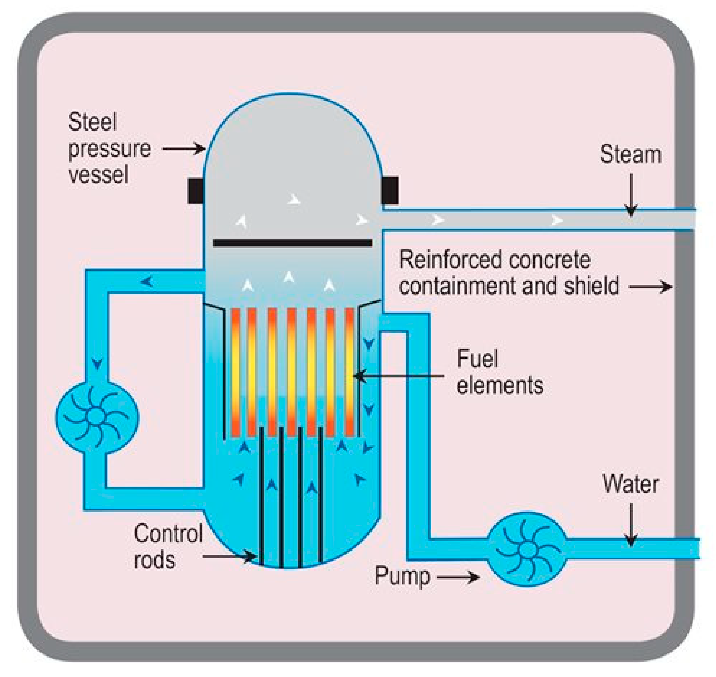
Boiling water reactors (BWRs) are the second most common type of nuclear reactors used in power engineering. They use pure light water as both a coolant and a moderator. A key feature of a BWR is that water is allowed to boil within the reactor core. The water is maintained at high pressure (ca. 75 atm.), which raises its boiling point to around 285 °C. The produced steam is used directly to drive the steam turbine. After expansion, the steam is cooled and condensed in the condenser, and the resulting condensate is pumped back to the core. In a boiling water reactor (BWR) (see Figure 5), convective heat transfer is an essential for transferring thermal energy from the nuclear fuel to the coolant. As the coolant (water) flows upward through the fuel assemblies, nucleate boiling occurs, causing bubbles to form on the surface of the fuel rods. The bubbles then detach, carrying away significant amounts of heat. As the bubbles rise, they coalesce into larger steam pockets, resulting in a steam–water mixture. This mixture carries thermal energy away from the core as it flows towards the top of the reactor vessel. Once the steam is generated, it flows from the top of the reactor vessel to the steam turbine.
Heat transfer in BWR reactors has been extensively studied and reported in the literature over the years. One of the main aspects frequently considered is heat transfer within the core, which significantly impacts reactor performance. A significant portion of this research focuses on analyzing reactor safety during hypothetical accidents. In this section of the paper, the authors review the literature on convective heat transfer in BWRs. The most important correlations related to convective heat transfer in boiling water reactors are summarized in Table 2.
In the model developed by Sun et al. [18], the heat transfer coefficients from the fuel rods to the steam–droplet mixture were calculated, which is typical for BWR reactors during emergency core cooling system operation under hypothetical loss-of-coolant accident conditions. Heat transfer coefficients were determined for various regions of the bundle, and the relationship between these coefficients and the size and concentration of the droplets was established. The Nusselt number, used to calculate droplet–vapor heat transfer, is given by Equation (13) in Table 2 (which is valid for the Reynolds number range of 17 < Re < 70,000). To validate their model, the authors compared its results with experimental data (see Figure 6).
Tran and Dinh [19] analyzed the late in-vessel phase of a severe core-melting accident in a nuclear power plant. Using the computational fluid dynamics (CFD), they simulated proposed methods for mitigating major failures, specifically the use of coolant flow in control rod guide tubes (CRGTs). The key aspect was the effective convectivity model (ECM), which describes the distribution of energy in the core melting pool. The computed heat flux profile for the control rod guide tubes (CRGTs) was compared with the analytical profile derived from the boundary layer model, using the Nusselt number calculated from Equation (14) in Table 2 (valid for Rayleigh number range of 108 < Ra < 1014). The heat flux was compared for different Prandtl and Rayleigh numbers. For a small Prandtl number (Pr = 0.56), a significant difference was observed between the analytical results and those obtained from the CFD model. The dependency of the Prandtl number was thoroughly studied, and its effect on the temperature of the vessel wall was established.
In [20], a severe accident involving core melt is considered. The authors simulated the core melt pool in a BWR reactor using the effective convectivity model. The equations used in the model to calculate the sideward, downward, and upward heat transfer of the pool, valid for a Rayleigh number range of 5·1012 < Ra < 3·1013 and a Prandtl number of Pr ≈ 7, are given by Equations (13), (16), and (17) in Table 2, respectively.
In [21], the authors aimed to reduce the uncertainty of the heat transfer analysis in the core melt pool of BWRs. This resulted in the development of improved correlations for the Nusselt number (see Equations (20)–(25) in Table 2).
Park et al. [22] performed an analysis of the accident management strategies for BWR reactors, specifically the flooding of the dry well. They examined whether the core would remain in the vessel after melting and being transferred to the lower head of the vessel, which was cooled externally. Using a two-dimensional implicit finite difference scheme, the authors conducted a numerical analysis of the thermal behavior of the vessel. Some initial assumptions were that the dry well was flooded prior to the slumping of the core material and that the flooded water had a temperature of 323 K. Equations (26)–(28) in Table 2 provide the general relation describing the average natural convection heat transfer coefficient for a submerged hemisphere. They used the relation for a sphere (Nu0 = 2), which is a good approximation for a hemisphere. The authors also conducted calculations to establish the conditions under which equilibrium can occur between the rate of steam generation and the condensation of steam on the skirt wall. These calculations assume that the sensible heat transferred from the vapor to the interface is negligible.
In the paper by Yoon et al. [23], a numerical analysis of the two-phase flow and heat transfer in BWR fuel assemblies was performed using a Eulerian M-CFD model with zero closure. The purpose of this research was to assess the capabilities of this model for such calculations. The results were compared with the international OECD/NRC BFBT benchmark data and showed a high degree of agreement with the experiments in terms of the local void fraction profile, subchannel void fraction, and exit quality. In their calculations, the Nusselt number was computed for each phase at the interface to model bulk boiling and condensation (see Equations (29) and (30)).
Hojerup et al. [24] investigated the possibility of reaching criticality in a BWR reactor after a severe accident and reflooding of the core with unborated water from the emergency core cooling system. They studied the power augmentation and the subsequent response of the containment and enhanced steam production following such recriticality. The authors used three different thermal hydraulic codes, employing Equations (31) and (32) from Table 2. Their results showed that reflooding the core, partially stripped of the control rods, yields a recritical power peak of considerable amplitude but short duration due to Doppler feedback. Continuous reflooding can again increase the fission power, potentially stabilizing at a level of ten percent of nominal power or more, with higher levels observed at higher reflooding flow rates.
Michel [25] proposed a new set of convective heat transfer coefficients for molten core pools (see Equations (33)–(38)). He considered a severe accident in BWR or PWR reactors, where, after core meltdown and vessel failure, corium would fall on the concrete reactor pit basement in the absence of water. The author modeled the heat transfer between an internally heated corium pool infused with gases from the thermal decomposition of concrete walls. Different lateral and horizontal superficial gas velocities were considered, and the obtained correlations were validated against the CLARA experimental program.
Espinosa-Parades et al. [26] studied the sensitivity of the mass flow rate in a boiling water reactor with natural circulation using the Monte Carlo method. The paper provides a detailed description of the thermal–hydraulic model that portrays the dynamic behavior of the lower and upper plenum and the reactor. The convective heat transfer model applied was based on Equations (39)–(43) from Table 2. The study examined the impact of the mass flow rate on various parameters, including the average void fraction in the core, average fuel temperature, total heat flux in the core, and neutron power. Additionally, the uncertainties of the results were analyzed.
In the work by Jauregui Chavez et al. [27], the TWOPORFLOW code is tested and its thermal–hydraulic computations (see Equation (44) in Table 2) are validated. TWOPORFLOW is a relatively new tool for simulating two-phase flow in structured or unstructured porous medium. In the context of a BWR reactor, the porous medium approach represents solid structures, including rods, as blocking volumes and areas. The code uses heat transfer coefficients to model the heat transfer from the fuel rod surface to the coolant. For convection in a single-phase liquid or vapor, the heat transfer is expressed in terms of the Nusselt number. For forced convection, the heat transfer coefficient is taken as the maximum of the single-phase liquid coefficient and the Chen heat transfer coefficient. The computations with TWOPOWRFLOW were validated using the BWR Full-size Fine-mesh Bundle Test (BFBT) benchmark. The results were promising, demonstrating the code’s ability to simulate BWR thermal–hydraulic behavior with a good accuracy.
Chen [28] introduced a new correlation for describing boiling heat transfer to saturated, nonmetallic liquids in convective flow (see Equations (45)–(51)). The research approach is based on two heat transfer mechanisms: the macroconvective, which operates in flowing fluids; and microconvective, which pertains to the nucleation and growth of bubbles. The correlation, tested for water and organic fluids, showed good results, making it applicable for heat transfer description in BWR reactors.
Sibamoto et al. [29] conducted an experiment to develop a model for predicting the heat transfer coefficient (see Equation (52) in Table 2) during post-boiling behavior in an anticipated operational occurrence (AOO). The experiment, performed on a vertically mounted test section, was conducted under pressures ranging from 2 to 7 MPa and total mass fluxes from 300 to 1000 kg/(m2s). The study simulated the thermal–hydraulic conditions typical of AOOs in BWRs. Measurements were taken of the heat transfer coefficient, liquid droplet deposition rate, and droplet concentration along the coolant flow direction. These measurements provided the boundary conditions necessary for studying post-boiling transitions.
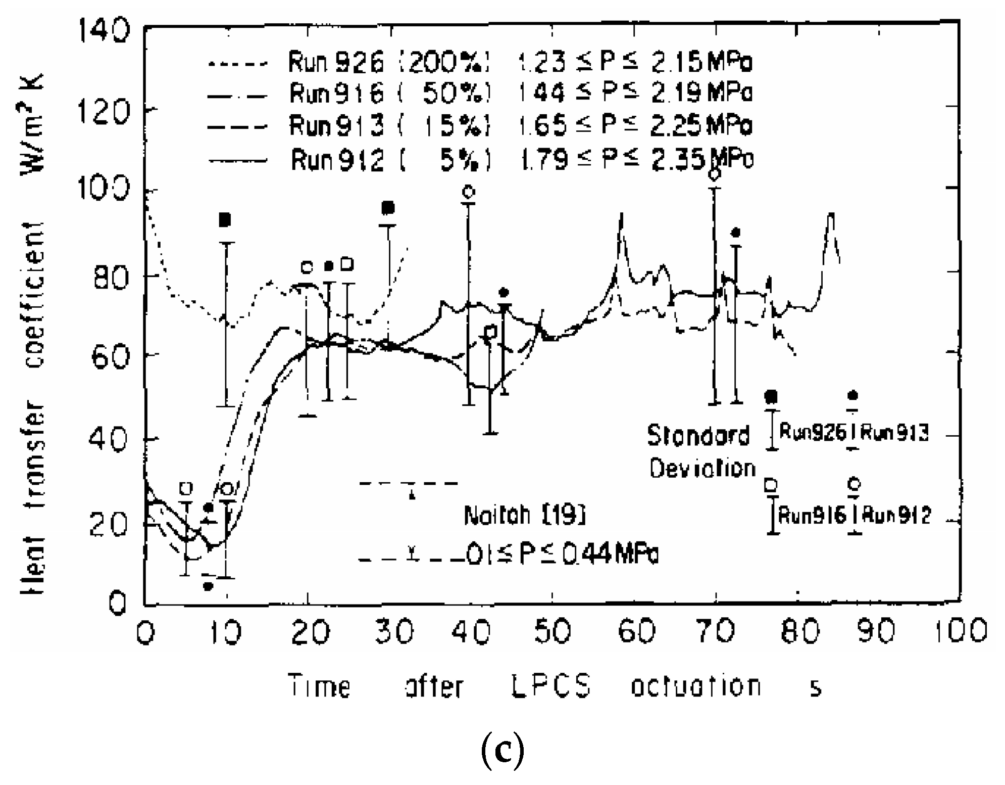
Yonomoto et al. [30] conducted experiments using the ROSA-III test facility, a volumetrically scaled simulator of the BWR/6 reactor, scaled to 1/424 of the original volume. This facility was employed to investigate the thermal–hydraulic behavior during loss-of-coolant accidents in BWRs. The core of the simulator includes a pressure vessel fitted with four electrically heated half-length fuel bundles, each comprising 62 simulated fuel rods and 2 water rods. The primary objective of the experiment was to establish a baseline for post-critical heat flux heat transfer coefficients and quench temperatures. Four different break tests (at 5%, 15%, 50%, and 200% break sizes) were conducted. The results are presented in charts showing the heat transfer coefficient as a function of time and pressure (see Figure 7).
In the experiment conducted by Griebe et al. [31] as a part of the BWR-FLECHT program, the thermal hydraulics of a BWR reactor during the emergency core cooling (ECC) injection portion of a loss-of-coolant accident (LOCA) were investigated. The tests utilized a full-length 7 × 7-rod electrically heated bundle, which simulated the decay power and cladding temperatures of nuclear fuel pins. The study focused on examining the effects of various test parameters on the heat transfer coefficients and bundle thermal characteristics. These parameters included the bundle’s initial power, flooding and spray rates, and the initial temperature of the bundle, under both steady and transient power conditions. In the project, the convective heat transfer coefficient was determined by subtracting the radiative heat transfer coefficient from the total heat transfer coefficient.
The report by Duncan et al. [32] details an experiment conducted as part of the FLECHT project, focusing on simulated transient loss-of-coolant scenarios. The tests were performed using a full-scale BWR fuel bundle mock-up with 49 rods. The authors investigated heat transfer mechanisms and measured fuel rod cladding temperatures as a function of the power level, initial temperature, and coolant spray flow rate. Convective heat transfer coefficients were calculated for various rod positions within the bundle and different times following the initiation of spray cooling. The experimental results demonstrated that spray cooling is an effective cooling method for BWR reactor cores. It was observed that convection significantly impacts the cooling of rods at the bundle edges, whereas radiation plays a more substantial role for rods situated further from the channel.
Eklund and Jevremovic [33] introduced a new thermal hydraulic integrated with the deterministic neutronics code AGENT. Their study explores two models: HEM for PWRs and drift flux model for BWRs (see Equations (53)–(56) in Table 2). The drift flux model is specially designed to address the challenges of two-phase heat transfer and the higher void fractions typical in BWRs. It assumes thermal equilibrium between the liquid and gas phases, along with velocity non-equilibrium. The code calculates coolant properties such as the temperature, pressure, and void fraction and also estimates the average temperature of the fuel within each fuel pin.
Cai et al. [34] investigated a new type of boiling water reactor featuring micro fuel elements referred to as the BWR-PB. In this reactor, the fuel assembly consists of a steel-walled tube containing millions of fuel particles, with coolant water flowing through the particle bed to fluidize it. The study utilized the heat transfer correlations provided by Equations (57)–(59) in Table 2. The water used as a moderator flows out of the tube in the opposite direction. The core, comprising 145 fuel assemblies, was analyzed for equilibrium conditions. The authors computed the pressure drop, void fraction, heat transfer coefficients, and temperature profiles of both the coolant and microfuel elements. They found that the core’s maximum temperature is significantly lower than the design limit and that the flow distribution meets the cooling requirement.
Sharma et al. [35] conducted a numerical analysis of a hypothetical core melt accidents and explored the method of in-vessel melt retention for managing such incidents. The study focused on both PWR and BWR reactors. In their simulations of heat transfer within the melt pool, the authors employed the Algebraic Heat Flux Model (see Equation (60) in Table 2). The study also included a comparison of the Nusselt numbers for the reactors under consideration.
In [36], the authors investigated a postulated core melt accident using the BH/MELCOR 1.8.4 code, considering both PWRs and BWRs. The study focused on scenarios where the core materials relocate to the lower plenum. The authors analyzed the convective heat transfer between the molten corium and the vessel wall and proposed modifications to the existing model (see Equations (61) and (62) in Table 2). The results indicated that the accident management strategy used in BWRs could be successful in mitigating core melt scenarios.
In [37], Valincius et al. investigated a severe loss-of-coolant accident involving the failure of cooling water injection. The study utilized the RELAP/SCDAPSIM MOD 3.4 code to simulate the full sequence of the accident. A key focus of the research was the separation of the molten core pool into oxidic and metallic phases and its impact on heat transfer. The simulations were performed for a 2000 MW thermal power BWR model, with calculations based on Equation (63) from Table 2.

4. CANDU Reactors

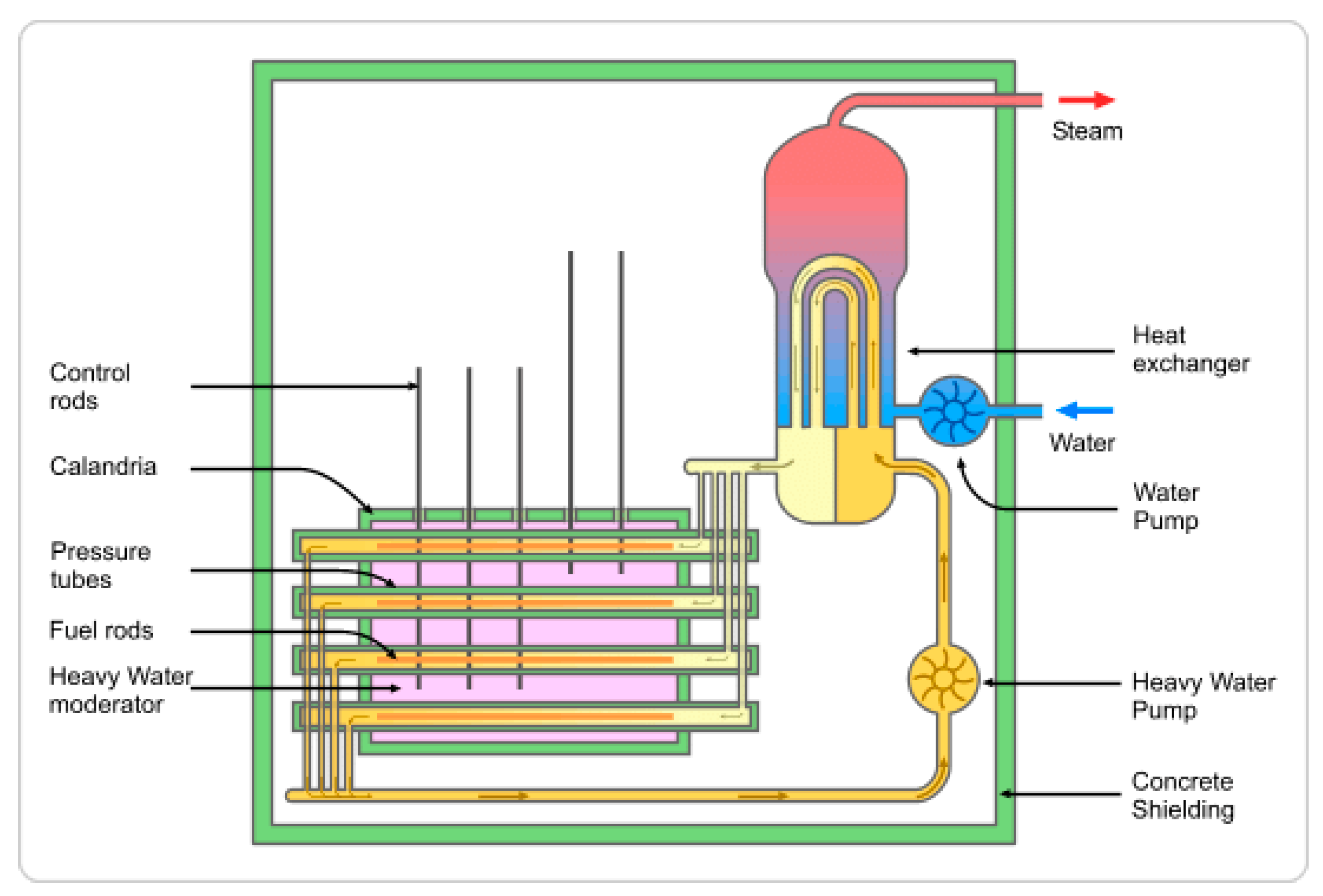
In the 1950s and 1960s, Canada decided to develop its own nuclear reactor named CANDU (CANada Deuterium Uranium). Unlike reactor designs from other countries, the CANDU reactor uses heavy water as a coolant. This choice allows the use of unenriched uranium fuel, as heavy water has a lower neutron absorption cross-section than light water. The CANDU reactor features a unique construction with a pressure tube design housed within a Calandria vessel. Figure 8 shows the schematic of the CANDU reactor. By 2016, there were 19 CANDU reactors operated in Canada and 9 in other countries. Effective heat transfer to the coolant is essential due to the significant amount of heat generated by the reactor.
Moreover, any potential disturbance in this process could lead to critical safety issues for the nuclear reactor. This section provides a review of literature on heat transfer and convection in CANDU reactors. The most important correlations related to convective heat transfer in CANDU reactors are summarized in Table 3.
Dittus and Boelter developed a correlation for heat transfer in fully developed turbulent flow within smooth tubes, specifically for fluids being heated (see Equation (64) in Table 3). This correlation is applicable to the convective process in CANDU reactors. It is suitable for pipes with a length to diameter ratio L/D ≥ 60 and for fluids with Prandtl numbers ranging from 0.7 to 100, Reynolds numbers greater than 10,000, or Prandtl numbers from 0.6 to 160 [39]. The exponent n = 0.4 is used for fluids being heated in the pipe, while n = 0.3 is used for fluid being cooled. This correlation can also be applied to supercritical heat transfer if the pressure is high and the heat flux is low. However, the correlation may yield inaccurate results under certain flow conditions due to its sensitivity to variations in the fluid properties. A comparison of the Dittus–Boelter correlation with other correlations is shown in Figure 9 [39].
The Colburn correlation (see Equation (65) in Table 3) is also used to determine the Nusselt number for turbulent flow, particularly for high-viscosity fluids. While both the Dittus–Boelter and Colburn correlations are commonly applied to typical fluids such as water [40,41,42], the correlation provided by Equation (66) in Table 3 is noted to offer greater accuracy. This correlation was developed following the Dittus–Boelter and Colburn correlations [39,42]. Bringer and Smith extended the Dittus–Boelter equation to account for supercritical water at an absolute pressure of 34.47 MPa, resulting in the correlation given by Equation (67) in Table 3. This equation shows the best performance near the critical point and is illustrated in Figure 10 which compares different temperatures [40].
Another correlation was developed by Miropol’skiy and Shitsman. Initially, Shitsman analyzed data on heat transfer in supercritical water and other fluids flowing in pipes. These data were then generalized, resulting in the correlation given by Equation (68) in Table 3. Notably, the minimum Prandtl number for this correlation is less than the Prandtl number calculated at the bulk fluid temperature and wall temperature. Krasnoshchekov and Protopopov derived additional correlations, given by Equations (69) and (70) in Table 3, which are applicable to forced-convective heat transfer in CANDU reactors. However, these correlations are primarily useful for heat transfer in water under supercritical pressure. The parameter “n” in these equations depends on the temperature ratios [43].
Jackson revised the Krasnoshchekov and Protopopov correlation by modifying the temperature ratios for the parameter “n,” as presented in the new equations. The applicability conditions for this correlation remained the same, but the updated Jackson correlation was found to yield the best results [44]. Kirillov developed new correlations (see Equations (71) and (72) in Table 3) for the Nusselt number that account for the role of free convection. These correlations are valid for supercritical fluids flowing inside a tube with constant heat flux and are particularly relevant near the critical point. The equations depend on the k* ratio [45]. When the k* ratio is smaller than 0.4 or Gr/Re2 is less than 0.6, the heat transfer decreases. Conversely, for higher values, heat transfer improves. For k* < 0.01, Equation (71) from Table 3 is used [46], while for k* > 0.01 Equation (72) is applied [45]. The parameter m is 0.4 for flow in a vertical tube and 0.3 for flow in a horizontal tube. Since CANDU reactors utilize horizontal tubes, the parameter n can be calculated for horizontal tubes using the method described in [47]. The function Φ(k*) can be found based on [48].
Domin, following experiments with supercritical water flowing inside horizontal tubes, developed two equations (see Equations (73) and (74) from Table 3), with the choice of equation depending on the fluid temperature [45]. Bishop et al. conducted experiments with supercritical water flowing upward inside bare tubes and created the correlation given by Equation (75) based on their results. The fit of these correlations is approximately +/- 15% [47,50]. Swenson et al. analyzed existing correlations and noted inaccuracies due to the use of the bulk fluid temperature as a basis for calculations, which led to deviations in the thermophysical properties of supercritical water. Consequently, they developed a new correlation where most properties are influenced by wall temperature (see Equation (77) in Table 3). Their results demonstrated that thermal conductivity varies with temperature near the critical and pseudocritical points, and the heat transfer coefficient is significantly influenced by the heat flux [51].
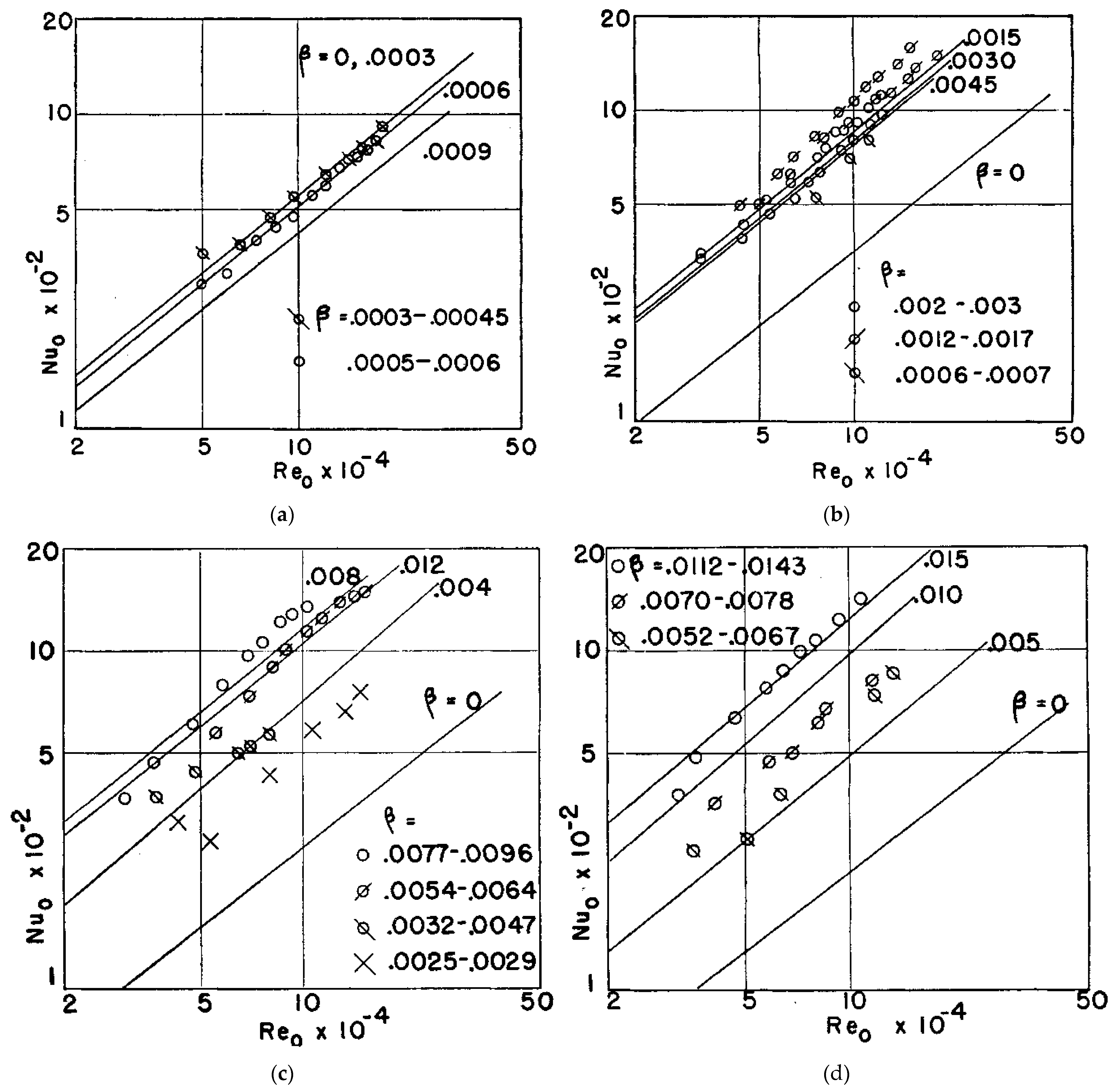
Yamagata et al. [49] conducted an experiment on forced convective heat transfer in supercritical water flowing through tubes. The experimental data were compared with the results from the obtained equation, as shown in Figure 11.
As a result, it was found that heat transfer deteriorates in the pseudocritical region at high heat fluxes relative to the flow rate. Additionally, the heat transfer coefficients for horizontal flow were found to be similar to those for vertical flow, but this similarity is observed only at sufficiently low heat fluxes. Based on these findings, Equation (76) from Table 3 was defined.
Griem [50] modified the Dittus–Boelter correlation through experimental methods, targeting forced convection heat transfer for supercritical and near-supercritical pressures. Two approaches were employed in this modification: the reference temperature method, which considers a characteristic temperature for estimating properties, and the property ratio method, which introduces a new dimensionless function based on the temperature values at the bulk and wall. The results led to the development of Equation (77) from Table 3. This new correlation proves effective for various heat transfer problems, particularly where the properties exhibit significant temperature dependence [50].
Kitoh et al. [51] developed the correlation given by Equation (78) in Table 3, applicable for describing forced convection at supercritical pressures, specifically during the safety analysis of a high-temperature reactor. This correlation is valid for fluid bulk temperatures ranging from 20 °C to 250 °C, fluid bulk enthalpies between 100 and 3300 kJ/kg, mass fluxes of 100 to 1750 kg/m2s, and thermal loads on waterwalls from 0.0 to 1.8 MW/m2. Both simulation and experimental results using this correlation were reported to be accurate [51].
Chen [52] developed new formulas (see Equations (80) and (81) in Table 3) for supercritical heat transfer. These formulas are based on experiments conducted in vertical and inclined smooth tubes. Chen examined two scenarios: one with uniform radial heating and one without, specifically for ribbed tubes. The resulting equations were derived for a smooth tube with a diameter of 26 mm and a length of 2 m, inclined at 20 degrees to the horizontal.

5. Small Modular Reactors (SMRs)

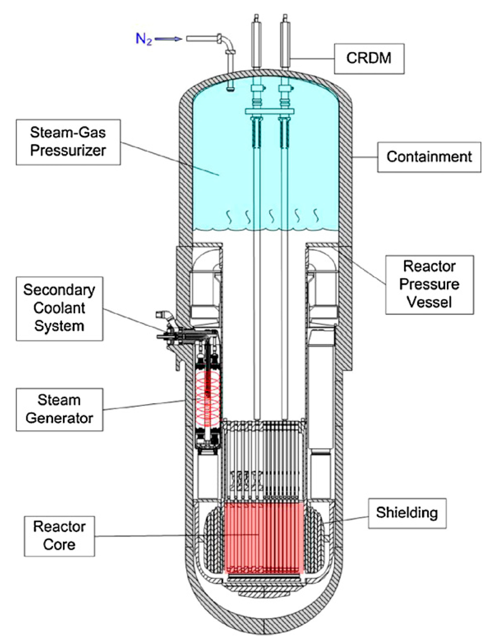
Small modular reactors (SMRs) have gained global attention as a viable solution to meet the growing energy demand [53]. Several countries with advanced nuclear technologies are developing their own SMR projects, including NuScale, BWRX-300, NUWARD, System-integrated Modular Advanced Reactor (SMART), AP300 SMR, International Reactor Innovative and Secure (IRIS), Autonomous transportable on-demand reactor module (ATOM), and Central Argentina de Elementos Modulares (CAREM) [54]. SMRs typically have a power capacity of up to 300 MW(e) per unit and generate substantial amounts of low-carbon electricity. The detailed design of an SMR is quite complex, presenting significant challenges in modeling. Consequently, in many cases, heat transfer analysis models have been simplified or focused on selected components [55]. Heat transfer in SMRs involves the movement of heat from the nuclear fuel to the coolant, typically facilitated by both natural and forced convection mechanisms. The compact design of SMRs enhances the efficiency of heat transfer by reducing the distance between the fuel and the coolant. Coolant flows around the fuel rods, absorbing the generated heat and then circulating it through the reactor system. Forced convection uses pumps to maintain a steady flow, while natural convection relies on the coolant’s buoyancy changes due to temperature gradients. Depending on the SMR type, the heat transfer process can vary. Factors that influence this include fuel composition, fuel enrichment, and the type of moderator and coolant (gas, liquid). The scheme of the REX-10 SMR is presented in Figure 12.
In the research presented by Lee et al. [56], a thermal–hydraulic system code named TAPIS was developed to analyze the transient behavior of 10 MW regional reactor REX-10. Mathematical models in TAPIS include models for the reactor coolant system, the core, the once-through helical-coil steam generator, and the built-in steam-gas pressure. The heat conduction equation can also be solved in the system code, providing radial temperature distribution in the fuel rods. The model used for convective heat transfer (see Equation (82) in Table 4) is suitable for free convection flows. However, for Re > 10,000 the given model is replaced with the Dittus–Boelter equation (see Equation (83) in Table 4) [57].
Xiang Chai and Wei Li [58] presented a numerical simulation of turbulent natural convection in a simplified enclosure with a curved surface heated from below. The relationship between the heat transfer characteristic and the curved surface, as well as the natural circulation used in SMR, is particularly important during unpredictable accidents. The average Nusselt number based on the simulation experiment with the RANS model is given by Equation (84) in Table 4. In addition to simulation research, the authors corrected Ulucakli’s experimental results [59] of heat transfer caused by turbulent natural convection in a rectangular enclosure (see Equation (85) in Table 4).
In [60], the authors presented a numerical study of the effect of geometry size on natural convection in a melt pool using ANSYS FLUENT 20.2. The Nusselt and Rayleigh numbers presented in experimental research by Zhou et al. [61] were calculated. The modified Rayleigh number in the experiment was the same for natural and forced convection and ranged from Ra = 1.270·1013 to Ra = 5.860·1015, but the Nusselt number was higher for the geometry of larger radius. The authors acknowledged that the Nusselt number (see Equation (86) in Table 4) obtained in the experiment conducted by Zhou et al. [61] exhibited results comparable to those they had calculated.
Songzhi Yang and Ulrich Bieder [62] performed a simulation of the turbulent natural convection boundary layer along a heated 15 m high vertical wall, on the SMR scale, in a water tank. Calculations were made by employing the Large Eddy Simulation strategy with the CEA in-house code Triocfd. The authors used Vliet’s heat transfer correlations for turbulent and laminar flow for Ra < 2 × 10¹⁶ [63], which matched the measured results. For a higher Ra number—up to 1019, which is the maximum Ra number that can be reached on the scale of SMR—they proposed a new heat transfer correlation (see Equation (87) in Table 4).
In [64], the authors proposed an innovative approach to integrate a dry air-cooling tower indirectly into the Passive Residual Heat Removal System (PRHRS) using an intermediate loop. This design facilitates the extraction of residual heat from the core once the stored water has been depleted. The indefinite PRHRS is expected to dissipate residual heat without exhausting the stored water. Heat transfer simulations were performed using the MARS code, with the Dittus–Boelter correlation as the default model. Before reaching the saturation temperature of the stored water, convective heat transfer was simulated using Equation (88) from Table 4, which accounts for the bundle effect. The study confirms the thermal–hydraulic feasibility of the indefinite PRHRS. However, addressing the economic and physical aspects remains necessary. While a larger emergency cooling tank volume may be cost-effective, it would necessitate resizing the containment.
In [65], the authors presented a simple model for a stratified corium pool, utilizing the Final Bounding State (FIBS) concept to assess the in-vessel melt retention (IVR) thermal load of the IP200 reactor, a small modular reactor (SMR) with a thermal power of 200 MW. They considered three configurations: a two-layer configuration with a light metal layer and an oxide layer, a three-layer configuration with a heavy metal layer at the bottom, and a water-layer configuration with cooling water on top. For FIBS modeling, it was assumed that all the corium material collapses into the lower head, and the pool contains the entire decay heat from the fuel. Additionally, under the assumption of a successful IVS condition, the mass composition, geometric structure, internal power, and temperature distribution remain constant. For the metal layer, two correlations were presented: one for top and bottom natural convection (see Equation (89) in Table 4) [66] and one for side natural convection. For the oxide layer, downward natural convection (see Equation (90) in Table 4) from the same author [66] and upward natural convection was modeled using an equation (see Equation (91) in Table 4) from Theofanous et al. [67]. The water layer significantly improves the cooling of the top surface.
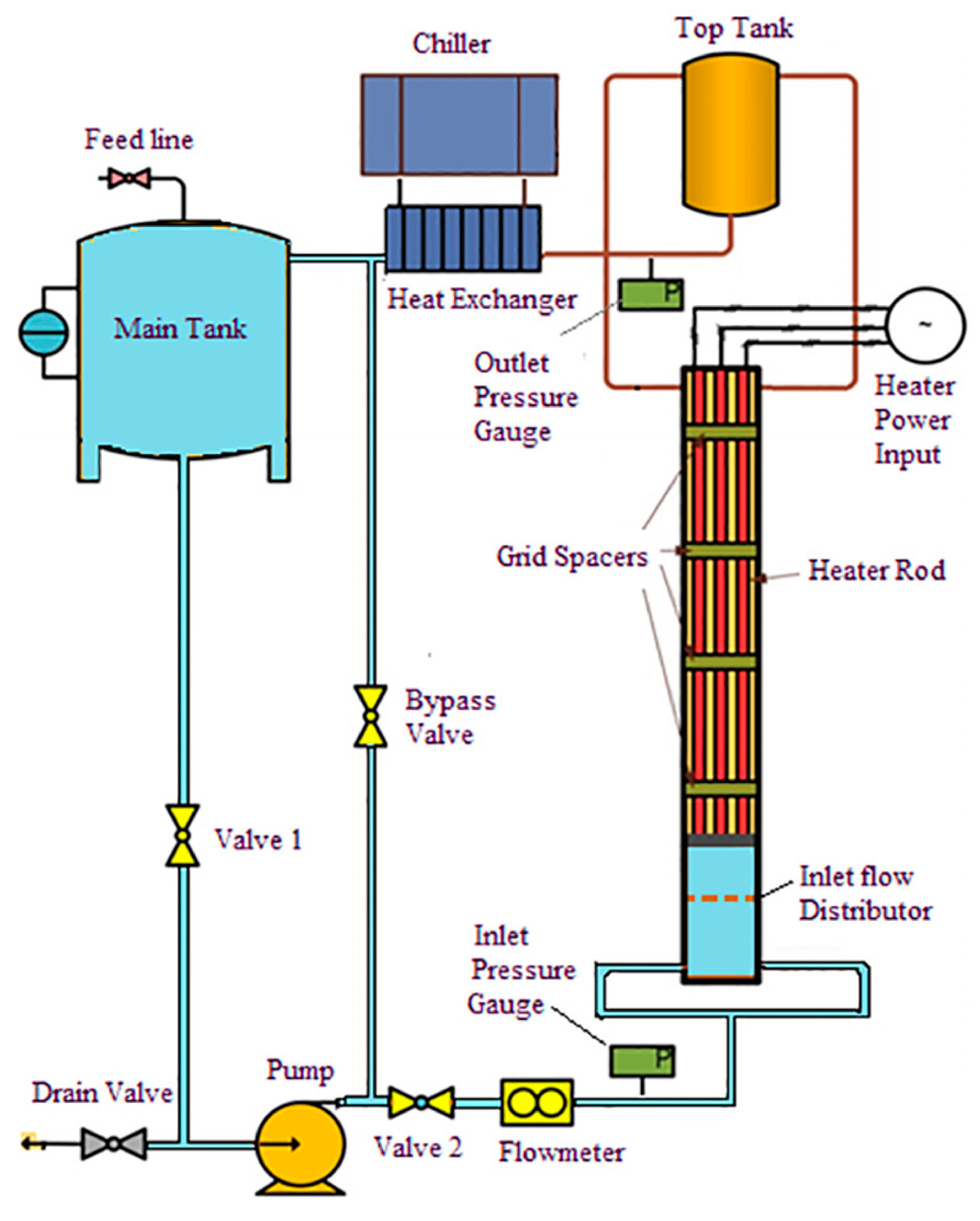
The authors of [68] designed a special rod bundle with grid spacers and flow distributors, called the NANO test facility, to simulate a unit block of the SMR core, as shown in Figure 13. They analyzed thermal–hydraulic characteristics under fully developed single-phase turbulent up flow using pure water and water mixed with alumina nanosize particles Al2O3. For heat transfer calculations, six correlations were presented; however, these models were developed using regular tube geometry, which differs from the rod bundle in the reactor. After experimentally determining the Nusselt number, the authors compared the different correlations with the applied one.
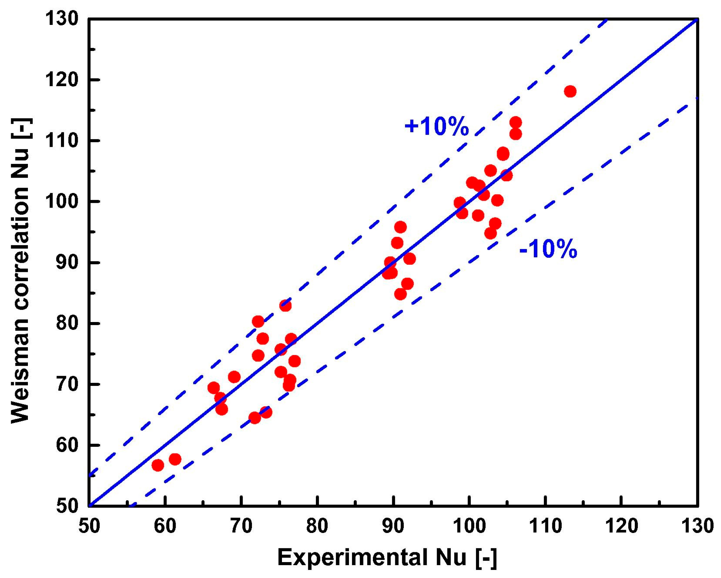
The correlation used for pure water (see Equation (92) in Table 4) was defined by Weisman [69]. The study, consistent with numerous previous research efforts, also found that the use of nanofluids improves the heat transfer efficiency.
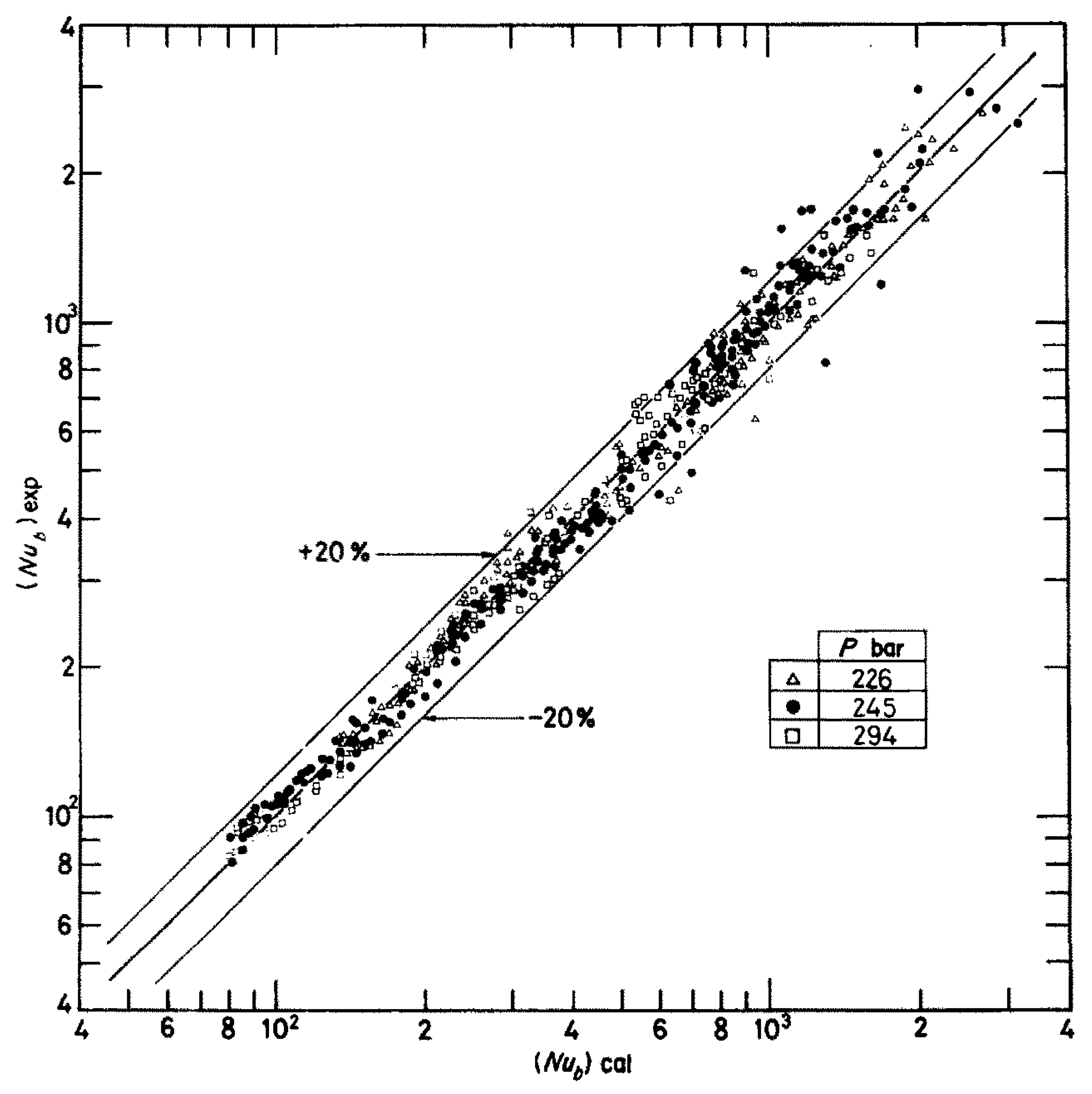
Da Liu et al. [70] conducted an experiment to investigate heat transfer at low flow rates in square 5 × 5 rod bundles with Reynolds numbers ranging from 1·103 to 3·104. The rod diameter was 10 mm with a pitch of 13.3 mm, and the test section length was approximately 3 m. The rods were uniformly heated using DC power and cooled with pressurized water. This study was aimed at examining mixed convection, a phenomenon increasingly relevant in SMRs. The experimental data indicated that Weisman’s [69] correlation accurately predicts forced turbulent convection with a deviation of less than 10%, but it tends to overestimate the Nusselt number under mixed convection conditions, as shown in Figure 14. Consequently, the authors proposed a new empirical correlation for forced turbulent convective heat transfer (see Equation (93) in Table 4) and mixed convective heat transfer in rod bundles (see Equation (94) in Table 4).
In [71], the results of thermophysical investigations of the KLT-40S reactor, a pressurized water SMR with a thermal power of 150 MW, were presented. The research demonstrated that changing the fuel composition from (U238 + U235)O2 to (Th232 + U233)O2 did not significantly affect the maximum fuel temperatures. However, increasing the diameter of the fuel rod was found to lower the maximum fuel temperature. The correlation used for the calculations was the Dittus–Boelter equation (see Equation (95) in Table 4).
Carlson et al. [72] investigated the implications of using HALEU (High-Assay Low-Enriched Uranium) fuel on the design of SMRs and micro-reactors, specifically using NuScale’s 160 MWt reactor as a model. The study aimed to assess how increased fuel enrichment affects reactor and to identify changes in various parameters. Neutronic analysis was performed using the Studsvik Scandpower reactor physics code suite, while thermal–hydraulic and economic analyses were conducted using conventional methods based on the neutronic analysis results. For Nusselt number estimation, the authors employed the Dittus–Boelter correlation, supplemented by a correction factor adapted to the lattice geometry of the fuel pins, as derived from Todereas and Kazimi research (see Equation (96) in Table 4) [73]. The study found that increasing fuel enrichment to HALEU levels can enhance the economic efficiency of SMRs, although extending the plant’s fuel cycle to 48 months is essential to realize this benefit.
In [73], the thermal–hydraulic development of a small, simplified, and proliferation-resistant 300 MWt reactor with liquid-metal cooling was presented. Equation (97) from Table 4 was used for calculating heat transfer both inside the core and in the steam generator. When applying this equation to the core, the power peaking factors and the local heat transfer coefficient factor were assumed to be unity. The peak cladding temperatures obtained with this approach were found to be comparable to those calculated using more detailed equations. The study demonstrated that reliable natural convection heat transport can be maintained throughout the 15-year cartridge lifetime.
El-Genk and Schriener [74] conducted a comprehensive review and correlation of convective heat transfer data from liquid metals and lead-bismuth eutectic, which are used in SMRs, specifically focusing on hexagonal bundles with helical spacers. The authors compared 103 Nusselt number correlations and identified two that most closely matched the existing database. Liquid metal-cooled nuclear reactors typically feature cores composed of hexagonal bundles of fuel rods or pins arranged in a triangular lattice. These bundles often include helical spacers such as wire wrap, metal fins, or ribs along the outer surface to enhance heat transfer. Equation (98) from Table 4 which is applicable for lead-bismuth eutectic and liquid sodium in hexagonal bundles of uniformly heated tubes with helical spacers was utilized. The resulting calculations were found to agree with most of the data within a ±15% margin.
Hao Yu et al. [75] developed a distributed parameter model for calculating the transient heat transfer of a molten-pool reactor. For these calculations, five empirical correlations for free convection from Zhang’s research [76] were evaluated. Among these, the Asfia–Dhir formula (see Equation (99) in Table 4) [77] was found to be the most accurate for calculating the averaged Nusselt number. The model’s accuracy was initially validated by comparing it with the LIVE-L5L experiment. Subsequently, an in-vessel melt retention scenario for an SMR with a core power of 220 MW was chosen for a trial calculation. The results demonstrated that the model effectively captured the primary phenomena associated with in-vessel melt retention, and the calculated parameters were consistent and reasonable.

6. Molten Salt Reactors (MSR)

Molten salt reactors (MSRs) are known for their positive thermal hydraulic performance due to good cooling characteristics of salts used as coolants. These reactors can operate at high temperatures, which significantly enhances thermal efficiency compared to other reactor types. Extensive research has been conducted on heat transfer in MSRs, yet many correlations found in the literature often overlook internal heat generation. Consequently, it is crucial to further investigate this topic to accurately predict the heat transfer coefficient in molten salts. This is essential for determining the graphite temperature, a critical parameter in MSR technology [79].
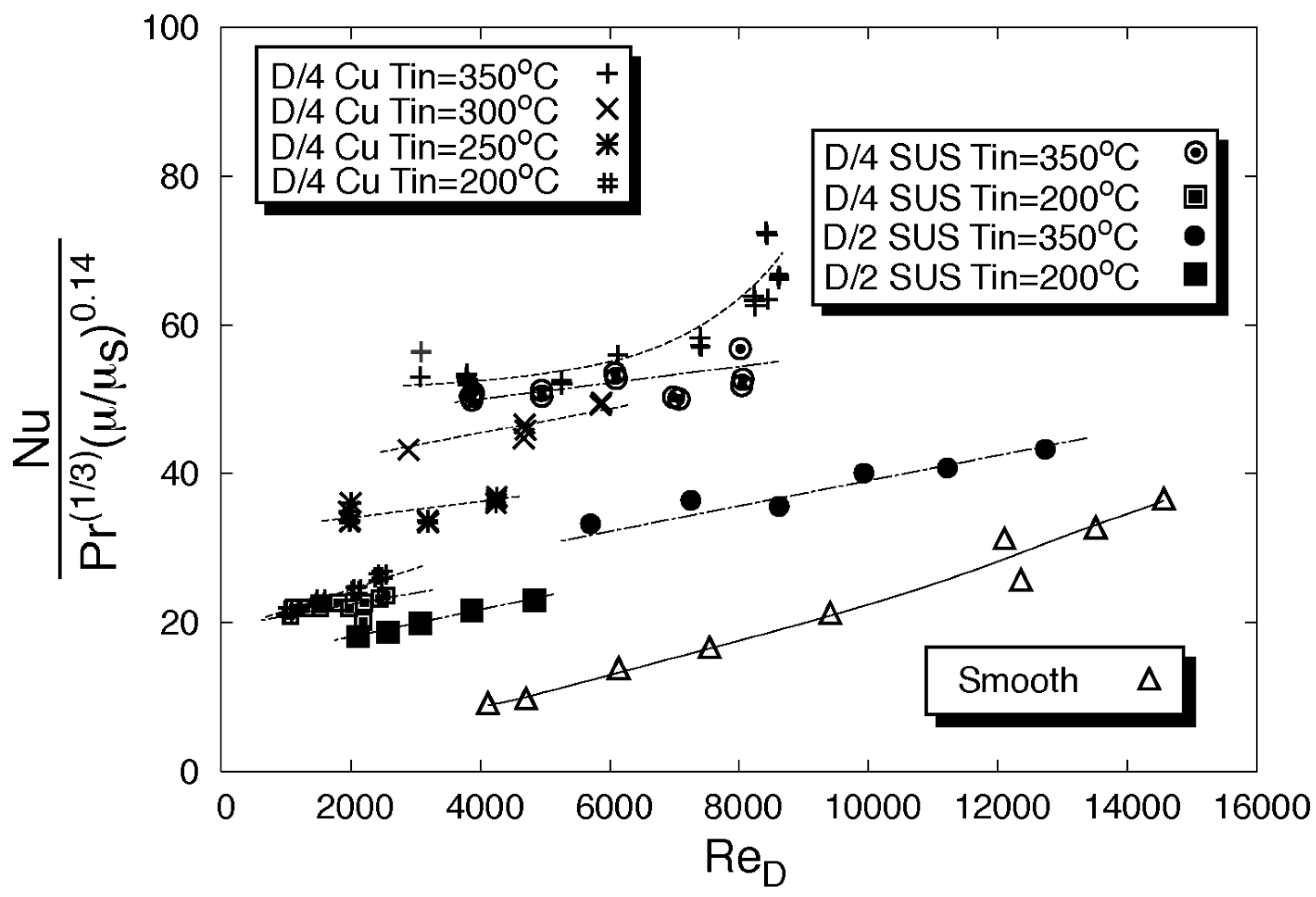
Chiba et al. [80] conducted experimental research on molten salt loop to enhance heat transfer through a packed bed tube. The packed bed was created using tightly packed metallic spheres. The results, presented as graphs showing the Nusselt number versus the Reynolds number, are illustrated in Figure 15. The correlation (see Equation (100) in Table 5) also accounts for the Prandtl number and the influence of the fluid’s dynamic viscosity. The study found that using a packed-bed tube can increase the Nusselt number more than threefold compared to smooth tubes. However, this method significantly increases the pumping power required.
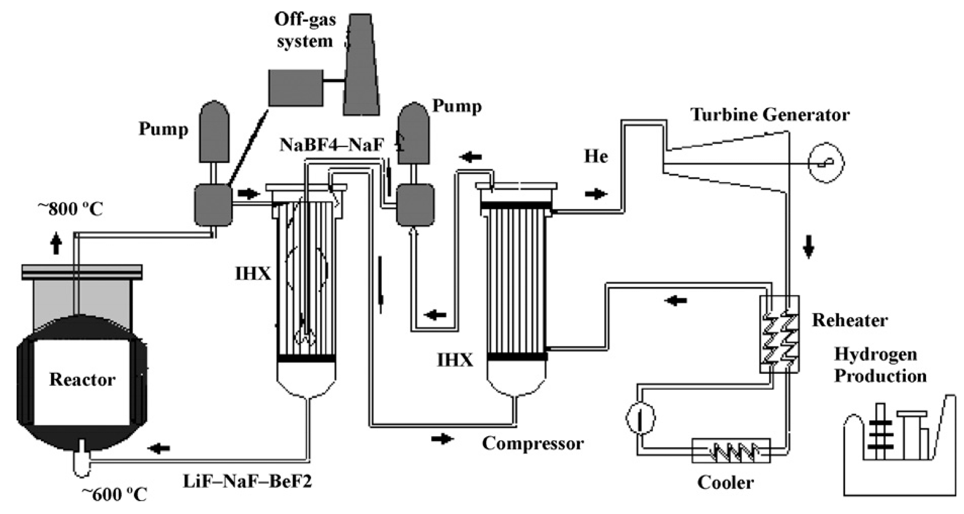
Some experimental studies have been conducted to estimate the Nusselt number correlations (see Equations (101)–(103) in Table 5) for molten salts flow in circular pipes [81,82]. The scheme of an MSR reactor system is depicted in Figure 16.
These studies cover a wide range of Reynolds numbers; however, they do not account for the internal heating of a molten salt, as occurs in MSRs.
Marcello et al. [83] conducted a numerical analysis over a wide range of Reynolds and Prandtl numbers for flow through a straight, smooth pipe in the context of MSR. They developed an axial-symmetric steady-state model suitable for turbulent flows (see Equations (104) and (105) in Table 5). The model was validated against data available in the literature. Moreover, the model was extended to include the effects of internal heat generation, and the results were formulated into a correlation for the Nusselt number.
Qian et al. [84] numerically investigated natural convection heat transfer for an MSR under zero-power or post-accident conditions using a two-dimensional cavity model (see Equation (106) in Table 5). The Rayleigh number ranged from 103 to 107. The model incorporated the Navier-Stokes equations for fluid motion and the transport equation for neutrons, and it was thoroughly validated against benchmark solutions from [85,86,87,88]. The authors examined temperature and velocity distributions and analyzed the impact of natural convection on the Nusselt number. Their findings, expressed using Equation (106) and illustrated in graphs, showed that natural convection increased the average Nusselt number at the top wall while having a reverse effect at the bottom wall.
Another numerical work has been performed by Luzzi et al. [79], who utilized COMSOL and Fluent software to analyze the thermal–hydraulic behavior of an MSR core channel. The model was validated against analytical solutions, showing very good agreement. The authors compared the numerical values of the Nusselt number for flow in a circular pipe with constant heat flux on the wall with existing correlations in the literature. They concluded that neglecting the source term could lead to a significant overestimation of the Nusselt number in MSRs. Figure 17 presents a comparison of various correlations for MSR with numerical results obtained by the authors.
Kudariyawar et al. [89] conducted an analysis of a molten salt natural circulation loop using CFD methods in both steady-state and transient modes. The study employed the Phoenics CFD code and utilized the k-ε turbulence model to represent turbulence. The model’s accuracy was validated against existing literature correlations. In transient mode, various power levels and configurations were investigated. The results were presented in graphs depicting the relationship between the Reynolds number and the modified Grashof number. The computed results showed good agreement with both the correlations and experimental data.
Shin et al. [90] investigated a scaled-down single-phase molten salt natural circulation loop experimentally and through simulations. In their study, Dowtherm oil was used as a simulant for molten salt. The experimental results were formulated into a Nusselt correlation (see Equation (107) from Table 5). Subsequently, the experimental loop was analyzed numerically using the MARS code and the commercial CFD code Ansys CFX. The numerical results showed an agreement within 30% of the experimental data. It was found that existing correlations tend to overestimate the Nusselt number compared to the experimental results obtained by the authors.
Liu et al. [91,92] conducted experimental studies on the passive heat removal system of molten salt reactors using heat pipes. Their research focused on the natural convection heat transfer of FLiNaK with inclined heat pipes. The study found that both the height of the heat pipe and the bulk temperature have only a minor impact on the temperature distribution. However, increasing the height of the heat pipe resulted in a more uniform temperature distribution of the molten salt and an increase in the heat transfer coefficient. The results were summarized with Nusselt number correlations (see Equations (108)–(111) from Table 5) that showed a 5% deviation from the experimental data.
Seo et al. [93] conducted thermal–hydraulic studies of MSRs using a similarity technique to simplify numerical experiments and avoid complexities associated with full-scale devices. Their research included numerical simulations across various MSR systems (i.e., MSFR, MOSART, MSBR). The calculated Nusselt numbers for these MSR systems showed a deviation of within 7% from theoretical values (see Equation (112) from Table 5). The study concluded that the similarity technique effectively reproduces the global thermal performance of MSRs.
Wang et al. [94] recently conducted a numerical investigation into passive residual heat removal for an MSR. The study focused on natural convection heat transfer involving fluoride salt and heat pipes within a drain tank. The numerical results were compared with experimental data, showing satisfactory accuracy. It was found that the intensity of natural convection increased with the height of the heat pipes. The findings were illustrated in a graph depicting the Nusselt number as a function of the Rayleigh number.

7. Summary and Conclusions

One of the most important aspects of ensuring the safe and efficient operation of a nuclear reactor is maintaining optimal heat transfer conditions. While the primary heat transfer mechanism within fuel pellets and clad is conduction, the heat is subsequently transferred from fuel elements to the coolant through convection. Selecting appropriate convection correlations is a key step in the design and modeling of nuclear reactors. This article reviews the convective heat transfer correlations applicable for practical calculations and modeling in the most common types of applied nuclear reactors, including PWR, BWR, CANDU, SMR, and MSR. For each reactor type, the correlations are categorized and presented in tables detailing their application ranges and limitations. The review provides into current research trends in the thermal hydraulics of nuclear reactors.
The most important findings related to convective heat transfer in nuclear reactors and the reviewed correlations can summarized as follows:
  • Convective heat transfer is crucial physical process that occurs in nuclear reactors, maintaining their thermal stability and efficiency. Effective heat removal from the reactor core via convection is essential to prevent overheating, which could lead to core damage or meltdown. The review shows that convective heat transfer correlations which applied for simulation of emergency states of nuclear reactors are intensively studied in case of BWRs (see Table 2) due to the specific heat transfer conditions that occur in these reactors, such as working fluid evaporation inside the core. These correlations can be practically applied in simulation and design calculations.
  • For each type of reviewed case, convective heat transfer can be characterized by specific correlations. The practical applicability of these correlations to other specific simulation or design cases can be assessed using similarity rules based on the heat transfer conditions and the limitations associated with each correlation (as detailed in Table 1, Table 2, Table 3, Table 4 and Table 5). The course of convective heat transfer in nuclear reactors is affected by various factors, such as thermo-physical properties of the coolant (i.e., viscosity, thermal conductivity, and specific heat), reactor geometry, surface characteristics of fuel rods, and the presence of turbulence. This finding is true for all types of studied reactors. Currently, there is a significant effort observed in research aimed at improving reactor design and applying innovative coolants (such as nanofluids) and simulating reactor failures (such as core meltdown). However, review results show that, especially in the case of PWRs, there is a large interest in the application of nanofluids to enhance heat transfer efficiency. The application of nanoparticles in coolant changes the thermophysical parameters of coolant; thus, a specific set of convective heat transfer correlations should be practically applied in simulation and design calculations (see Table 1).
    The review shows that in the case of CANDU-type nuclear reactors, the convective heat transfer correlations are similar to those practically applied for forced fluid flow inside the tubes (see Table 3).
    In the case of MSR reactors special set of correlations have to be applied in practical calculations and simulation due to the specific working fluid (see Table 4).
  • The convective heat transfer mechanism in nuclear reactors can include both natural and forced convection. These processes are particularly important in case of SMRs, where the heat transfer process can vary depending on SMR type. Factors that affect this process include fuel composition, fuel enrichment, and the type of moderator and coolant (gas or liquid). As a result, different correlations are practically applied for reactor calculations and modeling, depending on these variables (see Table 4).
  • Nowadays, advanced nuclear reactor models can be implemented and solved using computational fluid dynamics (CFD). CFD acts as a “virtual laboratory”, providing important insights into heat transfer and fluid flow processes.
It can be concluded that future research in this field should focus on experiments with innovative coolants, materials, and design improvements which may enhance convective heat transfer in the reactor core. Another important research direction is the improvement of convective heat transfer models and correlations, as well as simulation tools. This aim can be achieved through the application of computational fluid dynamics (CFD) and other multiphysics models of the nuclear reactors, which may provide deeper insights into the complex behaviors of convective heat transfer in nuclear reactors.
The following specific unresolved problems related to convective heat transfer in different types of nuclear reactors are identifiable from literature review:
  • In case of PWRs, most of the reviewed research consists of computational studies. The modeling of convective heat transfer processes often relies on classical correlations such as those by Dittus–Boelter, Mayinger et al., or Kulacki and Emara. However, there are a limited amount of experimental data available for validating these correlations. Consequently, more experimental research is needed on PWRs to better understand the influence of different conditions on convective heat transfer.
  • In case of BWRs, the two-phase flow during convective heat transfer adds significant complexity to the process. To perform simulations, researchers often need to make assumptions and simplifications, which can compromise the accuracy of the models. The limited number of experiments, particularly on full-scale BWR prototypes, further restricts the ability to validate and refine existing models. Additionally, further simulations of reactor behavior under abnormal and accident conditions remain crucial for comprehensive safety analysis.
  • Development of the CANDU reactor technology remains a key focus for the future, as improving heat transfer is crucial for enhancing the efficiency of these units. The geometry of fuel channels in CANDU reactors is complex, leading to potential variations in temperature within the core. This can result in hot spots and temperature fluctuations. Most existing correlations are developed for one-dimensional, stationary and turbulent flow conditions. To address the complexity of CANDU reactor cores and better understand the heat transfer dynamics, it would be valuable to conduct numerical simulations for correlations described.
  • SMR technology is among the most advanced in the nuclear power industry. As commercial SMRs and microreactors are some of the first of their kind, there are relatively little empirical data available to evaluate design concepts before implementation. Due to the wide variety of technologies used, detailed analyses must be conducted for each SMR design variation. Reactor heat transfer modeling is essential even before licensing. Design approval and licensing of reactor systems requires results that account for specific physical and test conditions. The biggest challenge for SMR technology is ensuring efficient heat transfer in the compact and densely packed reactor core to prevent hot spots and ensure uniform cooling. For instance, factors such as type of nuclear fuel and its enrichment, the shape and size of the reactor vessel, the type of coolant used, and the moderator can affect the maximum average fuel temperature, which is directly related to the heat transfer process in the SMR core. This makes experiments both complex and time-consuming. The unresolved issues in heat transfer and SMR technology include the ability to passively cool the reactor containment, increasing the life of nuclear fuel, improving safety and controlling the heat transfer process within the core.
  • Despite the existence numerical models for MSR, further development is necessary to enhance their reliability for predicting heat transfer in these reactors. Specifically, improvements are needed in modeling thermal–hydraulic phenomena where recirculation occurs. In such cases, accurately addressing turbulence is crucial for obtaining reliable results. Current models are predominantly axially-symmetrical or two-dimensional. The development of more complex 3D models, which include the entire core of an MSR, is highly desirable. However, this advancement would require significant computational resources.
In conclusion, continuous improvement in convective heat transfer in nuclear reactors is crucial for enhancing reactor efficiency, safety, and reliability. This progress is essential for the successful development of next-generation nuclear power systems. The review provides a comprehensive summary of correlations applicable to engineers and scientists working on heat transfer in nuclear reactors offering valuable insights for advancing reactor design and operation.

Author Contributions

Conceptualization, methodology, investigation, writing—original draft preparation, writing—review and editing, supervision, formal analysis, P.K.; investigation, writing—original draft preparation, writing—review and editing, D.S.; investigation, writing—original draft preparation, writing—review and editing, J.B.; investigation, writing—original draft preparation, writing—review and editing, A.P.; investigation, writing—original draft preparation, writing—review and editing, M.P.; methodology, investigation, writing—original draft preparation, writing—review and editing, supervision, formal analysis, P.B. All authors have read and agreed to the published version of the manuscript.

Funding

This research received no external funding.

Conflicts of Interest

The authors declare no conflicts of interest.

References

  1. El-Sefy, M.; Ezzeldin, M.; El-Dakhakhni, W.; Wiebe, L.; Nagasaki, S. System dynamics simulation of the thermal dynamic processes in nuclear power plants. Nucl. Eng. Technol. 2019, 51, 1540–1553. [Google Scholar] [CrossRef]
  2. Shamim, J.A.; Bhowmik, P.K.; Chen, X.; Suh, K.Y. A new correlation for convective heat transfer coefficient of water–alumina nanofluid in a square array subchannel under PWR condition. Nucl. Eng. Des. 2016, 308, 194–204. [Google Scholar] [CrossRef]
  3. Hatami, M.; Ganji, M.; Sohrabiasl, I.; Jing, D. Optimization of the fuel rod’s arrangement cooled by turbulent nanofluids flow in pressurized water reactor (PWR). Chin. J. Chem. Eng. 2017, 25, 722–731. [Google Scholar] [CrossRef]
  4. Liu, C.; Ferng, Y.; Shih, C. CFD evaluation of turbulence models for flow simulation of the fuel rod bundle with a spacer assembly. Appl. Therm. Eng. 2012, 40, 389–396. [Google Scholar] [CrossRef]
  5. Ghazanfari, V.; Talebi, M.; Khorsandi, J.; Abdolahi, R. Thermal–hydraulic modeling of water/Al2O3 nanofluid as the coolant in annular fuels for a typical VVER-1000 core. Prog. Nucl. Energy 2016, 87, 67–73. [Google Scholar] [CrossRef]
  6. Vieira, C.B.; Romero, G.A.; Su, J. Computational Simulation of Natural Convection of a Molten Core in Lower Head of a PWR Pressure Vessel. In Proceedings of the 18th International Conference on Nuclear Engineering, Xi’an, China, 17–21 May 2010. [Google Scholar]
  7. Mayinger, F. Examination of Thermalhydraulic Processes and Heat Transfer in a Core Melt; Institut fur Verfahrenstechnik der T. U.: Halle, Germany, 1976. [Google Scholar]
  8. Kulacki, F.A.; Emara, A.A. High Rayleigh Numbers Convection in Enclosed Fluid Layers with Internal Heat Sources; US Nuclear Regulatory Commission, Division of Reactor Safety Research: Rockville, MD, USA, 1975.
  9. Zhang, X.; Chen, H.; Liu, F.; Zhan, D. Transient 3D simulation for heating and melting process of PWR core after SBO. Ann. Nucl. Energy 2018, 115, 256–267. [Google Scholar] [CrossRef]
  10. Holloway, M.V.; Beasley, D.E.; Conner, M.E. Single-phase convective heat transfer in rod bundles. Nucl. Eng. Des. 2008, 238, 848–858. [Google Scholar] [CrossRef]
  11. Liu, C.C.; Ferng, Y.M. Numerically simulating the thermal–hydraulic characteristics within the fuel rod bundle using CFD methodology. Nucl. Eng. Des. 2010, 240, 3078–3086. [Google Scholar] [CrossRef]
  12. Yao, S.C.; Hochreiter, L.E.; Leech, W.J. Heat-Transfer Augmentation in Rod Bundles Near Grid Spacers. J. Heat Transf. 1982, 104, 76–81. [Google Scholar] [CrossRef]
  13. Holloway, M.V.; McClusky, H.L.; Beasley, D.E.; Conner, M.E. The Effect of Support Grid Features on Local, Single-Phase Heat Transfer Measurements in Rod Bundles. J. Heat Transf. 2004, 126, 43–53. [Google Scholar] [CrossRef]
  14. Hadad, K.; Rahimian, A.; Nematollahi, M. Numerical study of single and two-phase models of water/Al2O3 nanofluid turbulent forced convection flow in VVER-1000 nuclear reactor. Ann. Nucl. Energy 2013, 60, 287–294. [Google Scholar] [CrossRef]
  15. Pak, B.C.; Cho, Y.I. Hydrodynamic and Heat Transfer Study of Dispersed Fluids with submicron Metallic Oxide Particles. Exp. Heat Transf. 1998, 11, 151–170. [Google Scholar] [CrossRef]
  16. Maïga, S.E.B.; Nguyen, C.T.; Galanis, N.; Roy, G.; Maré, T.; Coqueux, M. Heat transfer enhancement in turbulent tube flow using Al2O3 nanoparticle suspension. Int. J. Numer. Methods Heat Fluid Flow 2006, 16, 275–292. [Google Scholar] [CrossRef]
  17. Fazio, S.; Recchioni, M.; Mathieux, F. (Eds.) Background Analysis of the Quality of the Energy Data to be Considered for the European Reference Life Cycle Database (ELCD); Publications Office of the European Union: Luxembourg, 2013. [Google Scholar]
  18. Sun, K.H.; Gonzalez-Santalo, J.M.; Tien, C.L. Calculations of Combined Radiation and Convection Heat Transfer in Rod Bundles under Emergency Cooling Conditions. J. Heat Transf. 1976, 98, 414–420. [Google Scholar] [CrossRef]
  19. Tran, C.T.; Kudinov, P.; Dinh, T.N. An approach to numerical simulation and analysis of molten corium coolability in a boiling water reactor lower head. Nucl. Eng. Des. 2010, 240, 2148–2159. [Google Scholar] [CrossRef]
  20. Tran, C.-T.; Dinh, T.-N. The effective convectivity model for simulation of melt pool heat transfer in a light water reactor pressure vessel lower head. Part I: Physical processes, modeling and model implementation. Prog. Nucl. Energy 2009, 51, 849–859. [Google Scholar] [CrossRef]
  21. Tran, C.-T.; Kudinov, P.; Toronto, H.; Tran, C.T. Local Heat Transfer from the Corium Melt Pool to the Boiling Water Reactor Pressure Vessel Wall. In Proceedings of the 14th International Topical Meeting on Nuclear Reactor Thermal Hydraulics (Nureth-14) Nureth14-182, Toronto, ON, Canada, 25–30 September 2011. [Google Scholar] [CrossRef]
  22. Park, H.; Dhir, V.K.; Kastenberg, W.E. Effect of External Cooling on the Thermal Behavior of a Boiling Water Reactor Vessel Lower Head. Nucl. Technol. 1994, 108, 266–282. [Google Scholar] [CrossRef]
  23. Yoon, S.-J.; Agostinelli, G.; Baglietto, E. Assessment of Multiphase CFD with Zero Closure Model for Boiling Water Reactor Fuel Assemblies. United States, 2017. Available online: https://www.osti.gov/biblio/1409683 (accessed on 16 July 2024).
  24. Højerup, F.; Miettinen, J.; Puska, E.K.; Anttila, M.; Lindholm, I.; Nilsson, L.; Sjoevall, H. On Recriticality during Reflooding of a Degraded Boiling Water Reactor Core. Denmark, 1997. Available online: https://inis.iaea.org/collection/NCLCollectionStore/_Public/28/059/28059598.pdf (accessed on 16 July 2024).
  25. Michel, B. New set of convective heat transfer coefficients established for pools and validated against CLARA experiments for application to corium pools. Nucl. Eng. Des. 2015, 286, 278–285. [Google Scholar] [CrossRef]
  26. Espinosa-Paredes, G.; Verma, S.P.; Vázquez-Rodríguez, A.; Nuñez-Carrera, A. Mass flow rate sensitivity and uncertainty analysis in natural circulation boiling water reactor core from Monte Carlo simulations. Nucl. Eng. Des. 2010, 240, 1050–1062. [Google Scholar] [CrossRef]
  27. Chavez, V.J.; Imke, U.; Sanchez-Espinoza, V. TWOPORFLOW: A two-phase flow porous media code, main features and validation with BWR-relevant bundle experiments. Nucl. Eng. Des. 2018, 338, 181–188. [Google Scholar] [CrossRef]
  28. Chen, J.C. Correlation for Boiling Heat Transfer to Saturated Fluids in Convective Flow. Ind. Eng. Chem. Process. Des. Dev. 1966, 5, 322–329. [Google Scholar] [CrossRef]
  29. Sibamoto, Y.; Maruyama, Y.; Yonomoto, T.; Nakamura, H. Core Heat Transfer Coefficients Immediately Downstream of the Rewetting Front during Anticipated Operational Occurrences for BWRs. J. Nucl. Sci. Technol. 2011, 48, 440–453. [Google Scholar] [CrossRef]
  30. Yonomoto, T.; Koizumi, Y.; Tasaka, K. Core heat transfer analysis during a BWR LOCA simulation experiment at ROSA-III. Nucl. Eng. Des. 1987, 103, 239–250. [Google Scholar] [CrossRef]
  31. Griebe, R.W.; McConnell, J.W. Boiling Water Reactor-Full Length Emergency Core Cooling Heat Transfer (BWR-FLECHT) Tests Project; Final Report on Atmospheric Pressure Stainless Steel Experiments; Aerojet Nuclear Co.: Idaho Falls, ID, USA, 1973. [CrossRef]
  32. Duncan, J.; Leonard, J. Heat Transfer in a Simulated BWR Fuel Bundle Cooled by Spray under Loss-of-Coolant Conditions; U.S. Atomic Energy Commission: Washington, DC, USA, 1970. [CrossRef]
  33. Eklund, M.D.; Jevremovic, T. AGENT-TH scheme: New thermal hydraulics (TH) code coupled with the AGENT neutronics code for light water reactors modeling and analysis. Prog. Nucl. Energy 2016, 92, 175–196. [Google Scholar] [CrossRef]
  34. Cai, X.; Qiu, S.; Su, G.; Zhao, C. Steady-State Thermal-Hydraulic Analysis of a Particle-Bedded Boiling Water Reactor. In Proceedings of the 17th International Conference on Nuclear Engineering, Brussels, Belgium, 12–16 July 2009; pp. 275–281. [Google Scholar] [CrossRef]
  35. Sharma, A.K.; Pellegrini, M.; Okamoto, K.; Furuya, M.; Mizokami, S. Validation and application of numerical modeling for in-vessel melt retention in corium pools. Int. J. Heat Mass Transf. 2022, 196, 123313. [Google Scholar] [CrossRef]
  36. Martín-Fuertes, F.; Martín-Valdepeñas, J.M.; Mira, J.; Sánchez, M.J. A MELCOR Application to Two Light Water Reactor Nuclear Power Plant Core Melt Scenarios with Assumed Cavity Flooding Action. Nucl. Technol. 2003, 144, 34–48. [Google Scholar] [CrossRef]
  37. Valinčius, M.; Kaliatka, T.; Kaliatka, A.; Ušpuras, E. Modelling of Severe Accident and In-Vessel Melt Retention Possibilities in BWR Type Reactor. Sci. Technol. Nucl. Install. 2018, 2018, 1–14. [Google Scholar] [CrossRef]
  38. Oettingen, M.; Skolik, K.; Malicki, M. Neutronic analysis of mixed thorium-uranium fuel bundle for CANDU reactors. IOP Conf. Ser. Earth Environ. Sci. 2019, 214, 012024. [Google Scholar] [CrossRef]
  39. Taler, D.; Taler, J. Simple heat transfer correlations for turbulent tube flow. E3S Web Conf. 2017, 13, 02008. [Google Scholar] [CrossRef]
  40. Yu, J.; Liu, H.; Jia, B. Sub-channel analysis of CANDU–SCWR and review of heat-transfer correlations. Prog. Nucl. Energy 2009, 51, 246–252. [Google Scholar] [CrossRef]
  41. Todreas, N.E.; Kazimi, M.S. Nuclear Systems Volume I, 3rd ed.; CRC Press: Boca Raton, FL, USA, 2021. [Google Scholar] [CrossRef]
  42. Alameri, S.A.; Alkaabi, A.K. Fundamentals of nuclear reactors. In Nuclear Reactor Technology Development and Utilization; Elsevier: Amsterdam, The Netherlands, 2020; pp. 27–60. [Google Scholar] [CrossRef]
  43. Han, S.H.; Choi, Y.D.; Shin, J.K.; Kim, Y.C.; Kim, M.S. Turbulent heat transfer of supercritical carbon dioxide in square cross-sectional duct flow. J. Mech. Sci. Technol. 2008, 22, 2563–2577. [Google Scholar] [CrossRef]
  44. Pioro, I.L.; Duffey, R.B. Literature Survey of Heat Transfer and Hydraulic Resistance of Water, Carbon Dioxide, Helium and Other Fluids at Supercritical and Near-Critical Pressures. 2003. Available online: https://inis.iaea.org/search/search.aspx?orig_q=RN:35087435 (accessed on 18 December 2023).
  45. Pioro, I.L.; Khartabil, H.F.; Duffey, R.B. Heat transfer to supercritical fluids flowing in channels—Empirical correlations (survey). Nucl. Eng. Des. 2004, 230, 69–91. [Google Scholar] [CrossRef]
  46. Zahlan, H.; Leung, L.; Huang, Y.; Liu, G. General Assessment of Convection Heat Transfer Correlations for Multiple Geometries and Fluids at Supercritical Pressure. CNL Nucl. Rev. 2017, 7, 1–20. [Google Scholar] [CrossRef]
  47. Mokry, S.; Pioro, I.; Farah, A.; King, K.; Gupta, S.; Peiman, W.; Kirillov, P. Development of supercritical water heat-transfer correlation for vertical bare tubes. Nucl. Eng. Des. 2011, 241, 1126–1136. [Google Scholar] [CrossRef]
  48. Debrah, S.K.; Shitsi, E.; Chabi, S.; Sahebi, N. Assessment of heat transfer correlations in the sub-channels of proposed rod bundle geometry for supercritical water reactor. Heliyon 2019, 5, e02927. [Google Scholar] [CrossRef]
  49. Yamagata, K.; Nishikawa, K.; Hasegawa, S.; Fujii, T.; Yoshida, S. Forced convective heat transfer to supercritical water flowing in tubes. Int. J. Heat Mass Transf. 1972, 15, 2575–2593. [Google Scholar] [CrossRef]
  50. Griem, H. A new procedure for the prediction of forced convection heat transfer at near- and supercritical pressure. Heat Mass Transf. 1996, 31, 301–305. [Google Scholar] [CrossRef]
  51. Kitoh, K.; Koshizuka, S.; Oka, Y. Refinement of Transient Criteria and Safety Analysis for a High-Temperature Reactor Cooled by Supercritical Water. Nucl. Technol. 2001, 135, 252–264. [Google Scholar] [CrossRef]
  52. Chen, W.; Fang, X.; Xu, Y.; Su, X. An assessment of correlations of forced convection heat transfer to water at supercritical pressure. Ann. Nucl. Energy 2015, 76, 451–460. [Google Scholar] [CrossRef]
  53. Lokhov, A.; Cameron, R.; Sozoniuk, V. OECD/NEA Study on the Economics and Market of Small Reactors. Nucl. Eng. Technol. 2013, 45, 701–706. [Google Scholar] [CrossRef]
  54. Carelli, M.D.; Ingersoll, D.T. (Eds.) Handbook of Small Modular Nuclear Reactors; Elsevier: Amsterdam, The Netherlands, 2015. [Google Scholar] [CrossRef]
  55. Kim, M.S.; Jeong, Y.H. Conceptual design of small modular reactor driven by natural circulation and study of design characteristics using CFD & RELAP5 code. Nucl. Eng. Technol. 2020, 52, 2743–2759. [Google Scholar] [CrossRef]
  56. Lee, Y.-G.; Kim, J.-W.; Park, G.-C. Development of a thermal–hydraulic system code, TAPINS, for 10 MW regional energy reactor. Nucl. Eng. Des. 2012, 249, 364–378. [Google Scholar] [CrossRef]
  57. Sundén, B. Advanced Heat Transfer Topics in Complex Duct Flows. In Advances in Heat Transfer; Elsevier: Amsterdam, The Netherlands, 2017; pp. 37–89. [Google Scholar] [CrossRef]
  58. Chai, X.; Li, W.; Chen, B.; Liu, X.; Xiong, J.; Cheng, X. Numerical simulation of turbulent natural convection in an enclosure with a curved surface heated from below. Prog. Nucl. Energy 2020, 126, 103392. [Google Scholar] [CrossRef]
  59. Ulucakli, M.E. Turbulent Natural Convection in an Enclosure with Localized Heating from Below. Exp. Heat Transf. 1996, 9, 305–321. [Google Scholar] [CrossRef]
  60. Venkateshwaran, A.; Kumar, M.; Kumar, S.; Sivakumar, R.; Joshi, A.; Pain, C. Numerical study of the effect of geometry on the behaviour of internally heated melt pools for in-vessel melt retention. Prog. Nucl. Energy 2023, 156, 104555. [Google Scholar] [CrossRef]
  61. Zhou, Y.; Zhang, Y.; Luo, S.; Tian, W.; Qiu, S.; Su, G. Results of simulant effect on large corium pool behavior based on COPRA facility. Prog. Nucl. Energy 2018, 108, 398–408. [Google Scholar] [CrossRef]
  62. Yang, S.; Bieder, U. LES of Natural Convection Along the Vertical Wall Applied for the Scale of Small Modular Reactor (Ra* ≈ 1019). In Proceedings of the Advances in Thermal Hydraulics (ATH 2022), Anaheim, CA, USA, 12–16 June 2022; pp. 311–314. [Google Scholar] [CrossRef]
  63. Vliet, G.C.; Liu, C.K. An Experimental Study of Turbulent Natural Convection Boundary Layers. J. Heat Transf. 1969, 91, 517–531. [Google Scholar] [CrossRef]
  64. Na, M.W.; Shin, D.; Park, J.H.; Lee, J.I.; Kim, S.J. Indefinite sustainability of passive residual heat removal system of small modular reactor using dry air cooling tower. Nucl. Eng. Technol. 2020, 52, 964–974. [Google Scholar] [CrossRef]
  65. Jiang, N.; Peng, M.; Cong, T. Thermal margin evaluation for the stratified molten pool in SMR-IP200. Nucl. Eng. Des. 2019, 355, 110354. [Google Scholar] [CrossRef]
  66. Globe, S.; Dropkin, D. Natural-Convection Heat Transfer in Liquids Confined by Two Horizontal Plates and Heated From Below. J. Heat Transf. 1959, 81, 24–28. [Google Scholar] [CrossRef]
  67. Theofanous, T.; Liu, C.; Additon, S.; Angelini, S.; Kymäläinen, O.; Salmassi, T. In-vessel coolability and retention of a core melt. Nucl. Eng. Des. 1997, 169, 1–48. [Google Scholar] [CrossRef]
  68. Bhowmik, P.K.; Shamim, J.A.; Chen, X.; Suh, K.Y. Rod bundle thermal-hydraulics experiment with water and water-nanofluid for small modular reactor. Ann. Nucl. Energy 2021, 150, 107870. [Google Scholar] [CrossRef]
  69. Weisman, J. Heat Transfer to Water Flowing Parallel to Tube Bundles. Nucl. Sci. Eng. 1959, 6, 78–79. [Google Scholar] [CrossRef]
  70. Liu, D.; Gu, H. Mixed convection heat transfer in a 5 × 5 rod bundles. Int. J. Heat Mass Transf. 2017, 113, 914–921. [Google Scholar] [CrossRef]
  71. Beliavskii, S.; Alhassan, S.; Danilenko, V.; Karvan, R.; Nesterov, V. Effect of changing the outer fuel element diameter on thermophysical parameters of KLT-40S reactor unit. Ann. Nucl. Energy 2023, 190, 109877. [Google Scholar] [CrossRef]
  72. Carlson, L.; Miller, J.; Wu, Z. Implications of HALEU fuel on the design of SMRs and micro-reactors. Nucl. Eng. Des. 2022, 389, 111648. [Google Scholar] [CrossRef]
  73. Farmer, M.T.; Hill, D.J.; Sienicki, J.J.; Spencer, B.W.; Wade, D.C. Thermal-Hydraulic Development a Small, Simplified, Proliferation-Resistant Reactor; No. ANL/RE/CP—98725; Argonne National Lab.: Lemont, IL, USA, 1999.
  74. El-Genk, M.S.; Schriener, T.M. Convection heat transfer of alkali liquid metals and LBE in hexagonal bundles of uniformly heated tubes with helical spacers. Therm. Sci. Eng. Prog. 2018, 5, 339–350. [Google Scholar] [CrossRef]
  75. Yu, H.; Peng, M.; Jiang, N.; Wang, H. Model development for the transient heat transfer in a corium pool. Nucl. Eng. Des. 2021, 371, 110946. [Google Scholar] [CrossRef]
  76. Zhang, L.; Zhou, Y.; Zhang, Y.; Tian, W.; Qiu, S.; Su, G. Natural convection heat transfer in corium pools: A review work of experimental studies. Prog. Nucl. Energy 2015, 79, 167–181. [Google Scholar] [CrossRef]
  77. Asfia, F.J.; Dhir, V.K. An experimental study of natural convection in a volumetrically heated spherical pool bounded on top with a rigid wall. Nucl. Eng. Des. 1996, 163, 333–348. [Google Scholar] [CrossRef]
  78. Churchill, S.W.; Chu, H.H. Correlating equations for laminar and turbulent free convection from a horizontal cylinder. Int. J. Heat Mass Transf. 1975, 18, 1049–1053. [Google Scholar] [CrossRef]
  79. Luzzi, L.; Cammi, A.; Di Marcello, V.; Fiorina, C. An approach for the modelling and the analysis of the MSR thermo-hydrodynamic behaviour. Chem. Eng. Sci. 2010, 65, 4873–4883. [Google Scholar] [CrossRef]
  80. Chiba, S.-Y.; Omae, M.; Yuki, K.; Hashizume, H.; Toda, S.; Sagara, A. Experimental Research on Heat Transfer Enhancement for High Prandtl-Number Fluid. Fusion Sci. Technol. 2005, 47, 569–573. [Google Scholar] [CrossRef]
  81. Liu, B.; Wu, Y.-T.; Ma, C.-F.; Ye, M.; Guo, H. Turbulent convective heat transfer with molten salt in a circular pipe. Int. Commun. Heat Mass Transf. 2009, 36, 912–916. [Google Scholar] [CrossRef]
  82. Wu, Y.-T.; Liu, B.; Ma, C.-F.; Guo, H. Convective heat transfer in the laminar–turbulent transition region with molten salt in a circular tube. Exp. Therm. Fluid Sci. 2009, 33, 1128–1132. [Google Scholar] [CrossRef]
  83. Di Marcello, V.; Cammi, A.; Luzzi, L. A generalized approach to heat transfer in pipe flow with internal heat generation. Chem. Eng. Sci. 2010, 65, 1301–1310. [Google Scholar] [CrossRef]
  84. Qian, L.; Qiu, S.; Zhang, D.; Su, G.; Tian, W. Numerical research on natural convection in molten salt reactor with non-uniformly distributed volumetric heat generation. Nucl. Eng. Des. 2010, 240, 796–806. [Google Scholar] [CrossRef]
  85. Boroushaki, M. Numerical solution of the neutron transport equation using cellular neural networks. Ann. Nucl. Energy 2009, 36, 15–27. [Google Scholar] [CrossRef]
  86. De, G.; Davis, V. Natural Convection of Air in A Square Cavity a Bench Mark Numerical Solution. Int. J. Numer. Methods Fluids 1983, 3, 249–264. [Google Scholar]
  87. Lee, J.-H.; Goldstein, R.J. An Experimental Study on Natural Convection Heat Transfer in an Inclined Square Enclosure Containing Internal Energy Sources. J. Heat Transf. 1988, 110, 345–349. [Google Scholar] [CrossRef]
  88. May, H.-O. A numerical study on natural convection in an inclined square enclosure containing internal heat sources. Int. J. Heat Mass Transf. 1991, 34, 919–928. [Google Scholar] [CrossRef]
  89. Kudariyawar, J.Y.; Aidya, A.M.V.; Maheshwari, N.K.; Satyamurthy, P.; Srivastava, A.K. Estimating Steady State and Transient Characteristics of Molten Salt Natural Circulation Loop Using CFD. Available online: www.hanser-elibrary.com (accessed on 16 July 2024).
  90. Shin, Y.; Bin Seo, S.; Kim, I.G.; Bang, I.C. Natural circulation with DOWTHERM RP and its MARS code implementation for molten salt-cooled reactors. Int. J. Energy Res. 2016, 40, 1122–1133. [Google Scholar] [CrossRef]
  91. Liu, M.; Zhang, D.; Wang, C.; Qiu, S.; Su, G.; Tian, W. Experimental study on the heat transfer characteristics of fluoride salt in the new conceptual passive heat removal system of molten salt reactor. Int. J. Energy Res. 2018, 42, 1635–1648. [Google Scholar] [CrossRef]
  92. Liu, M.; Zhang, D.; Wang, C.; Qiu, S.; Su, G.; Tian, W. Experimental study on heat transfer performance between fluoride salt and heat pipes in the new conceptual passive residual heat removal system of molten salt reactor. Nucl. Eng. Des. 2018, 339, 215–224. [Google Scholar] [CrossRef]
  93. Bin Seo, S.; Shin, Y.; Bang, I.C. Numerical analysis on spatial universality of similarity technique inside molten salt reactor system. Int. J. Heat Mass Transf. 2018, 116, 569–580. [Google Scholar] [CrossRef]
  94. Wang, C.-L.; Qin, H.; Zhang, D.-L.; Tian, W.-X.; Su, G.-H.; Qiu, S.-Z. Numerical investigation of natural convection characteristics of a heat pipe-cooled passive residual heat removal system for molten salt reactors. Nucl. Sci. Tech. 2020, 31, 1–9. [Google Scholar] [CrossRef]
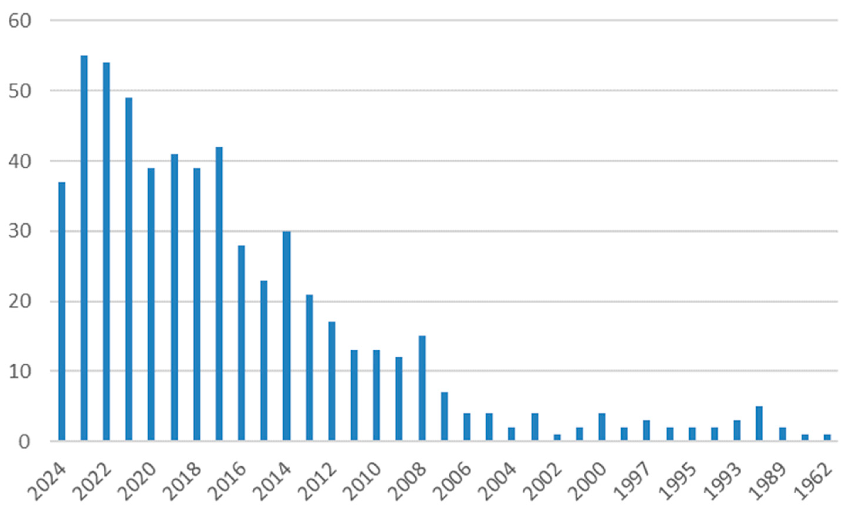
Figure 1. The number of yearly published articles related to convective heat transfer in nuclear reactors.
Energies 17 03652 g001
Figure 2. Diagram of a nuclear power plant with a PWR [1].
Energies 17 03652 g002
Figure 3. Difference in temperature profiles of the nanofluid between rods in examined geometries [3].
Energies 17 03652 g003
Figure 4. Comparison of axial fuel temperature distribution in annular fuel between the base fluid (water) and fluids with 10 and 20% of nanoparticles [5].
Energies 17 03652 g004
Figure 5. Simplified scheme of the boiling water reactor (BWR) [17].
Energies 17 03652 g005
Figure 6. Comparison of experimental Nusselt numbers with CFD predictions [18].
Energies 17 03652 g006
Figure 7. Convective heat transfer as a function of (a) time for steam cooling period; (b) system pressure in the steam cooling period; (c) time in the spray cooling period [30].
Energies 17 03652 g007aEnergies 17 03652 g007b
Figure 8. Simplified scheme of a CANDU reactor [38].
Energies 17 03652 g008
Figure 9. Comparison of the Dittus–Boelter correlation with other correlations [39].
Energies 17 03652 g009
Figure 10. Nu0 = f(Re0, β): (a) t = 37.8 °C; (b) t = 43.5 °C; (c) t = 54.5 °C; (d) t = 65.5 °C [40].
Energies 17 03652 g010
Figure 11. Experimental data compared with the results from the obtained equation [49].
Energies 17 03652 g011
Figure 12. Scheme of REX-10 [56].
Energies 17 03652 g012
Figure 13. Schematic diagram of a NANO test facility [68].
Energies 17 03652 g013
Figure 14. Comparison of experimental forced turbulent convection Nu with Weisman correlation predicted Nu [69].
Energies 17 03652 g014
Figure 15. Results of heat transfer enhancement for MSR using a packed bed [80].
Energies 17 03652 g015
Figure 16. Scheme of molten salt reactor system [84].
Energies 17 03652 g016
Figure 17. Comparison of Nusselt number in terms of Reynolds number between numerical results and correlations for MSR from the literature [79] (black dots—COMSOL; grey dots—FLUENT; navy solid line—Dittus and Boelter, 1930; orange solid line—Colburn, 1933; black solid line—Sieder and Tate, 1936; brown solid line—Petukhov, 1970; blue solid line—Gnielinski, 1976; green solid line—Hausen, 1959; red dashed line—Yu et al., 2001; grey solid line—Bin et al., 2009; pink solid line—Yu-ting et al., 2009; red solid line—Di Marcello et al., 2010).
Energies 17 03652 g017
Table 1. The convective heat transfer correlations valid for PWR nuclear reactors.
Ref.Field of the Research and ConditionsCorrelationRemarks/Applicability and LimitationsEquation No.
[2,3,15,16]Hydro and thermo-dynamics 3D simulation of water–alumina nanofluid in a square array subchannel under typical PWR conditions (single-phase, turbulent flow, normal operation mode). The studies included both theoretical and numerical modeling. N u = 0.021 R e 0.8 P r 0.5 N u n f = β ( N u Pr e s s e r ) w a t e r
β = 1 + 0.0247 φ 1.39
φ is the volume concentration of nanoparticles, %
3·105Re ≤ 6·106
0.847 ≤ Pr ≤ 1.011
1.25 ≤ P/D ≤ 1.35
0.5% ≤ φ ≤ 3.0%
(1)
N u = 0.085 R e 0.71 P r 0.35 Re = 104–5·105(2)
[6,7,8]Computational 2D simulation of turbulent natural convection of a molten core (emergency mode). N u t o p = 0.36 R a 0.23 Pr = 7.0
107Ra ≤ 5·1010
(3)
N u t o p = 0.54 R a 0.18 (4)
N u t o p = 0.403 R a 0.226 2.75 ≤ Pr ≤ 6.85
Ra ≤ 2·1012
(5)
[9]Numerical 3D simulation of transient heat transfer and melting process after a station blackout (emergency mode). N u = 0.15 ( G r   P r ) 1 / 3 ( P r f / P r w ) 0.1 < RaL1/4
d/L < 32
For water
(6)
N u L R a L 1 / 4 = 0.59 + 0.52 ( R a L 1 / 4 d L ) 1 (7)
N u L R a L 1 / 4 = 0.95 ( R a L 1 / 4 d L ) 0.79 0.0006 < RaL1/4
d/L < 0.1
For steam
(8)
[10]Experimental study of single-phase, turbulent convective heat transfer within the rod bundle area during normal operation. N u f d = 0.018 R e 0.79 (9)
N u a v g N u f d = 1 + ( 0.8 K g 0.4 ) e 0.25 z / D Nuavg/Nufd—heat transfer enhancement;
Kg—support grid pressure loss coefficient
z—axial coordinate direction
Dhydraulic diameter of typical subchannel
(10)
[11,12]3D computational simulation of thermal–hydraulic characteristics within the fuel rod bundle during normal operation mode (turbulent flow, single-phase). ( N u N u 0 ) = 1 + 5.55 e 2 e 0.13 ( x / D ) Nu0—fully developed Nusselt number
x—the axial distance from the downstream end of spacer
D—hydraulic diameter of flow channel
(11)
[13]Experimental study on the impact of support grids on local, single-phase, turbulent heat transfer. N u N u 0 1 + 6.5 ε S 2 e 0.8 z / D h 2800 ≤ Ra ≤ 42,000
1.4 ≤ z/Dh ≤ 33.6
εs—blockage ratio of base grid strap with no flow-enhancing features
z—axial coordinate direction
Dh—hydraulic diameter of typical subchannel
(12)
Table 2. The convective heat transfer correlations valid for BWR nuclear reactors.
Ref.Field of the Research and ConditionsCorrelationRemarks/Applicability and LimitationsEquation No.
[18]Combined radiation and convection heat transfer in rod bundles under emergency cooling conditions, (numerical, emergency conditions, two-phase, laminar, stationary, 3D). N u = h d d k = 0.37 R e 0.60 17 < Re < 70,000(13)
[19]Simulation and analysis of molten corium coolability in a boiling water reactor lower head (numerical, accidental conditions, two-phase, turbulent, non-stationary, 3D). N u s i d e l o c a l = 0.508 P r 1 / 4 ( 20 21 + P r ) 1 / 4 R a 1 / 4 108 < Ra < 1014(14)
[20]Simulation of melt pool heat transfer in a light water reactor pressure vessel lower head. Part I: Physical processes, modeling and model implementation (numerical, accidental conditions, two-phase, turbulent, non-stationary, 3D). N u u p = 0.345 R a 0.233 5·1012 < Ra < 3·1013
Pr ≈ 7
(15)
N u s i d e = 0.85 R a 0.19 (16)
N u d o w n = 1.389 R a 0.095 (17)
[21]Local heat transfer from the corium melt pool to the boiling water reactor pressure vessel wall (numerical, accidental conditions, two-phase, turbulent, non-stationary, 3D). N u u p = 0.366 R a 0.233 P r 0.11 Ra = 5.86·1012
0.03 < Pr < 1.02
(18)
N u s i d e = 0.92 R a 0.19 P r 0.125 (19)
N u d o w n ( r ) = 10 N u S R NuSR—Steinberner–Reineke correlation
Pr = 0.56
0 ≤ r ≤ 0.01 m
(20)
N u d o w n ( r ) = N u S R + 9 N u S R ( 0.035 r 0.025 ) Pr = 0.56
0 ≤ r ≤ 0.01 m
(21)
N u d o w n ( r ) = N u S R Pr = 0.56
0.035 m < r
(22)
N u d o w n ( r ) = 6.5 N u S R Pr = 0.03
0 ≤ r ≤ 0.02 m
(23)
N u d o w n ( r ) = N u S R + 5.5 N u S R ( 0.07 r 0.05 ) Pr = 0.03
0.02 m ≤ r ≤ 0.07 m
(24)
N u d o w n ( r ) = N u S R Pr = 0.03
0.07 m < r
(25)
[22]Effect of external cooling on the thermal behavior of a boiling water reactor vessel lower head (numerical, accidental conditions, laminar, single-phase, stationary, 2D). N u 1 / 2 = N u 0 1 / 2 + { R a / 300 [ 1 + ( 0.5 P r ) 9 / 16 ] 16 / 9 } 1 / 6 Nu0 = 2 for spheres Nu0 = 0.36 for horizontal cylinders
Nu0 = 0.68 for vertical plates
Ra = 1.24·1017
(26)
N u x = 0.707 [ h f g ρ l ( ρ l ρ v ) g x 3 κ l μ l ( T i T w ) ] 1 / 4 Local Nusselt number for laminar film condensation on the vertical wall(27)
N u x = 0.508 G r x 1 / 4 Pr 1 / 2 ( 0.952 + Pr ) 1 / 4 Local Nusselt number for natural convection on vertical plate(28)
[23]Assessment of multiphase CDF with zero closure model for boiling water reactor fuel assemblies (numerical, normal operation, turbulent, two-phase, 3D). q ˙ c o n v = ρ l c p l u l * t l + ( T w T l ) Convective heat flux for liquid contact with the wall(29)
q ˙ c o n v = ρ g c p g u g * t g + ( T w T g ) Convective heat flux for vapor contact with the wall(30)
N u l = 0.185 R e g 0.7 P r l 0.5 (31)
[24]Reflooding of a degraded boiling water reactor core (numerical, accident conditions. two-phase, turbulent, non-stationary, 3D). N u l = 0.0023 R e l 0.8 P r l 0.4 Re > 2000;
Nu = 4.36 for Re < 2000
(32)
[25]New set of convective heat transfer coefficients established for pools and validated against CLARA experiments for application to corium pools (numerical, accidental conditions, two-phase, turbulent, 2D). h h = 0.6 h D e c k w e r ( j g h ) + 0.4 h S h a y k u ( j g p o o l ) For pools of molten core,
BWR and PWR
v—vertical;
h—horizontal;
jg—superficial gas velocity
(33)
h v = 0.6 h S h a y k u ( j g h + j g v ) + 0.4 h S h a y k u ( j g p o o l ) (34)
S t S h a y k u = 0.148 ( R e F r P r 2.5 ) 0.223 ReFrPr2.5 < 101.95(35)
S t S h a y k u = 0.2 ( R e F r P r 2.5 ) 0.29 ReFrPr2.5 ≥ 101.95(36)
S t D e c k w e r = 0.075 ( R e F r P r 2 ) 0.25 ReFrPr2.5 < 103(37)
S t D e c k w e r = 0.1 ( R e F r P r 2 ) 0.29 ReFrPr2.5 ≥ 103(38)
[26]Mass flow rate sensitivity and uncertainty analysis in natural circulation boiling water reactor core from Monte Carlo simulations, (numerical, normal operation, single-phase, stationary, 1D). H 1 ϕ = 0.023 R e 1 ϕ 0.8 P r 1 ϕ 0.4 k l D h (39)
H 2 ϕ = H N B + H c (40)
H c = 0.023 R e 2 ϕ 0.8 P r 2 ϕ 0.4 k l D h (41)
H N B = 0.00122 f ( p ) ( T c l T s a t ) 0.99 S (42)
f ( p ) = ( k f 0.79 C p f 0.45 ρ f 0.49 σ 0.5 μ f 0.29 h f g 0.24 ρ g 0.24 ) ( h f g T s a t v f g ) 0.75 (43)
[27]TWOPORFLOW: A two-phase flow porous media code, main features and validation with BWR-relevant bundle experiments (numerical, accidental condition and normal operation, two-phase, stationary and transient, 3D). h l = 2.35 h f c ( X t t 1 + 0.213 ) 0.736 Xtt is the Martinelli parameter(44)
[28]Correlation for boiling heat transfer to saturated fluids in convective flow (numerical, normal operation, two-phase, turbulent, non-stationary, 3D). h m a c = 0.023 R e L 0.8 P r L 0.4 k L D F (45)
F = ( R e R e L ) 0.8 = ( R e μ L D G z ) 0.8 (46)
N u b = 0.0015 R e b 0.62 P r L 0.33 = h b r b k L b—boiling
(47)
r b = Δ T λ ρ v ( 2 π k L ρ L C p L σ Δ P ) 0.5 ( ρ L g c Δ P ) 0.25 (48)
R e b = π k L C p L μ L ( ρ L Δ T ρ v λ ) 2 (49)
h m i c = 0.00122 k L 0.79 C p L 0.45 ρ L 0.49 g c 0.25 σ 0.5 μ L 0.29 λ 0.24 ρ v 0.24 ( Δ T ) 0.24 ( Δ P ) 0.75 S S approaches unity at a zero flow rate and zero at an infinite flow rate.(50)
h = h m i c + h m a c mac—macroconvective
mic—microconvective
(51)
[29]Core heat transfer coefficients immediately downstream of the rewetting front during anticipated operational occurrences for BWRs (experimental, abnormal conditions, turbulent, two-phase, non-stationary, 3D). N u N u = [ 1 + n A n exp ( 4 γ n 2 R e z d ) ] 1 Fluid is assumed to have a fully developed turbulent velocity profile throughout the length of a pipe
Pr = 0.7, 10, 100
50,000 < Re < 500,000
γ2n and An are dimensionless eigenvalues and constants, respectively
(52)
[33]AGENT-TH scheme: New thermal hydraulics (TH) code coupled with the AGENT neutronics code for light water reactors modeling and analysis (numerical, normal operation, two-phase, 1-, 2-, and 3D, non-stationary). L e 0.05 R e P r D h Le—entry length, distance of travel, before it fully develops (laminar flow)(53)
N u = 1.86 ( D h R e P r L ) 1 / 3 Before the flow reaches the entry length, L < Le 0.48 < Pr < 16 700(54)
N u = 4.36 For the fully developed region, LLe(55)
N u = 0.023 R e 0.8 P r 0.4 For turbulent flow (Re > 10,000),
0.7 < Pr < 160
(56)
[34]Steady-state thermal–hydraulic analysis of a particle-bedded boiling water reactor (analytical, normal operation, turbulent, stationary, two-phase, 3D). N u = 2 + 1.8 R e 0.5 P r 1 / 3 Single-phase flow(57)
Δ T = 25 q 0.25 e P / 6.2 Subcooled boiling(58)
N u = 1.27 P r 1 / 3 ε 1 / 18 R e 0.36 + 0.033 P r 1 / 2 ε 1.07 R e 0.86 Single vapor flow(59)
[35]Validation and application of numerical modeling for in-vessel melt retention in corium pools, (numerical, accidental conditions, turbulent, single-phase, stationary, 3D). N u ¯ = 0.014 R a i n t 0.3581 1015 < Raint < 1017(60)
[36]A MELCOR application to two light water reactor nuclear power plant core melt scenarios with assumed cavity flooding action (numerical, accidental conditions, turbulent, non-stationary, single-phase, 2D). N u d n = h L c k = 0.54 R a 0.2 ( H R ) 0.25 1011 < Ra < 1014(61)
N u u p = 0.223 R a 0.223 P r 0.239 (62)
[37]Modeling of severe accident and in-vessel melt retention possibilities in BWR type reactor (numerical, accidental conditions, single-phase, stationary, 2D). N u u p = 0.345 R a 0.233
N u d n = 0.0038 R a 0.35
N u = 0.069 R a 1 / 3 Pr 0.074
R a = G r P r D a
First two are for the oxidic layer, third for the metallic(63)
Table 3. The convective heat transfer correlations valid for CANDU nuclear reactors.
Ref.Field of the Research and ConditionsCorrelationRemarks/Applicability and LimitationsEquation No.
[39,40]Simple heat transfer correlations for turbulent tube flow (turbulent, 3D, single-phase, experimental, stationary). N u = 0.023 R e 0.8 P r n L/D ≥ 60
0.7 < Pr < 10
0.6 < Pr < 160
Re > 10,000
n = 0.4 heated
n = 0.3 cooled
(64)
[41,42]Heat transfer correlations for turbulent flow with high viscosity (turbulent, 1D, single-phase, experimental, stationary). N u = 0.023 R e 0.8 P r 1 / 3 (65)
[39,42]Gnielinski correlation (turbulent, 1D, single-phase, experimental, stationary). N u = ( f 2 ) ( R e 1000 ) P r 1 + 12.7 ( P r 2 / 3 1 ) f 2 (66)
[40]Heat transfer in the critical region (transitional, 1D, single-phase, experimental, stationary). N u x = 0.0266 ( R e x ) 0.77 ( P r 0 ) 0.55 Nux and Rex are evaluated at temperature tx:
tx = tb for E < 0
tx = tpe for 0 ≤ E ≤ 1
tx = tw for E > 1
E = ( t p e t b ) ( t w t b )
(67)
[7,9,10,11]Heat transfer to water and steam at variable specific heat at near-critical region (turbulent, 1D, single-phase, experimental, stationary). N u b = 0.023 R e b 0.8 P r min 0.8 (68)
[44]Heat transfer at supercritical region in flow of carbon dioxide and water in tubes, (turbulent, 1D, single-phase, experimental, stationary). N u b = 0.0183 R e b 0.82 P r b 0.5 ( ρ w ρ b ) 0.3 ( c ¯ p c p b ) n n = ( 0.4 T w T p c 1     o r     T b T p c 1.2 n 1 = 0.22 + 0.18 T w T p c 1 T w T p c 2.5 n 1 + ( 5 n 1 2 ) ( 1 T b T p c ) 1 T b T p c 1.2 (69)
Consideration of the heat transfer properties of supercritical pressure water in connection with the cooling of advanced nuclear reactors, (turbulent, 1D, single-phase, experimental, stationary). N u b = 0.0183 R e b 0.82 P r b 0.5 ( ρ w ρ b ) 0.3 ( c ¯ p c p b ) n n = ( 0.4 T w T p c 1     o r     T b T p c 1.2 0.4 + 0.2 ( T w T p c 1 ) 1 < T w T p c     a n d     T b T p c < 1 0.4 + 0.2 ( T w T p c 1 ) ( 1 5 ( T b T p c 1 ) ) 1 < T w T b     a n d     1 < T b T p c < 1.2 (70)
[43,44,45,46,47,48,49]Heat transfer to supercritical fluids flowing in channels (1D, stationary and nonstationary). k * > 0.01 N u N u 0 = ( c ¯ p c p b ) n ( ρ w ρ b ) m Role of free convection in heat transfer
k * = ( 1 ρ w ρ b ) G r Re 2 n = ( 0.4 T w T p c 1     o r     T b T p c 1.2 0.22 + 0.18 T w T p c 1 < T w T p c     a n d     T b T p c < 1 0.9 T b T p c ( 1 T w T p c ) + 1.08 T w T p c 0.68 1 < T w T b     a n d     1 < T b T p c < 1.2
(71)
k * > 0.01 N u N u 0 = ( c ¯ p c p b ) n ( ρ w ρ b ) m φ ( k * ) Nu0 is the local value under turbulent flow in the circular tube [46](72)
[45]Supercritical water flowing inside horizontal tubes. N u b = 0.1 R e b 0.66 P r b 1.2 tw ≥ 350 °C
p = 233–263 MPa
q = 0.58–4.65 MW/m2
(73)
N u b = 0.036 R e b 0.8 P r b 0.4 ( μ w μ b ) 250 °C < tw < 350 °C(74)
[47,50]Forced convection heat transfer to water at near-critical temperature and supercritical pressures (turbulent, 1D, single-phase, experimental, stationary). N u b = 0.0069 R e b 0.9 P r ¯ b 0.66 ( ρ w ρ b ) 0.43 ( 1 + 2.4 D x ) p = 22.7–27.6 MPa
tb = 282–527 °C (bulk temperature)
G = 651–3662 kg/m2s (mass flux)
q = 0.31–3.46 MW/m2
(75)
[49]Forced convective heat transfer to supercritical water flowing in tubes (turbulent, 1D, single-phase, experimental, stationary). N u b = 0.0135 R e b 0.85 P r b 0.8 F c F c = ( 1.0 t p c t b t w t b > 1.0 0.67 Pr p c 0.05 ( c ¯ p c p b ) n 1 0 t p c t b t w t b 1.0 ( c ¯ p c p b ) n 2 t p c t b t w t b < 0 n 1 = 0.77 ( 1 + 1 / Pr p c ) + 1.49 n 2 = 1.44 ( 1 + 1 / Pr p c ) 0.53 (76)
[50]A new procedure for the prediction of forced convection heat transfer at near- and supercritical pressure (1D, laminar or turbulent, single-phase, experimental with some numerical modifications, stationary). N u b = 0.0169 R e b 0.8356 P r b 0.432 Modified Dittus–Boelter where constant is lowered to 70%(77)
[51]Heat transfer to supercritical water in smooth-bore tubes (1D, turbulent, stationary, experimental based empirical equation, single-phase). N u w = 0.00459 R e w 0.923 P r ¯ w 0.613 ( ρ w ρ b ) 0.231
where,
N u w = h D k w Pr ¯ w = H w H b T w T b μ w k w Re w = G D μ w
p = 22.9–41.4 MPa
tb = 75–576 °C (bulk temperature)
tw = 93–649 °C (bulk temperature)
G = 542–2150 kg/m2s (mass flux)
(78)
[51]Refinement of transient criteria and safety analysis for a high temperature reactor cooled by supercritical water (1D, turbulent, stationary, experimental based empirical equation, single-phase). N u = 0.015 R e 0.85 P r m m = 0.69 81000 q d h t + f c q
Low enthalpy (0–1.5 MJ/kg)
fc = 2.9·10−8 + 0.11/qdet
Intermediate enthalpy (1.5–3.3 MJ/kg)
fc = −8.7·10−8–0.65/qdet
High enthalpy (3.3–4.0 MJ/kg)
fc = −9.7·10−7 + 1.30/qdet
(79)
[52]Two-Phase Flow and Heat Transfer Study (turbulent, 1D, two-phase, experimental, stationary). N u b = 0.00271 R e b 0.93 P r ¯ 0.88 ( ρ w ρ b ) 0.52 ( k w k b ) 0.21 Hb > Hpc(80)
N u b = 0.0784 R e b 0.72 P r ¯ 0.79 ( ρ w ρ b ) 0.75 ( k w k b ) 0.1 Hb < Hpc(81)
Table 4. The convective heat transfer correlations valid for SMR nuclear reactors.
Ref.Field of the Research and ConditionsCorrelationRemarks/Applicability and LimitationsEquation No.
[56]Development of a thermal–hydraulic system code, TAPINS, for a 10 MW regional energy reactor (numerical, turbulent, 1D, stationary, single-phase, stable). N u = ( 0.825 + 0.387 R a 1 6 [ 1 + ( 0.492 P r ) 9 16 ] 8 27 ) 2 Re < 10,000(82)
[57] N u D B = 0.023 R e 0.8 P r 0.4 Re > 10,000(83)
[58]Numerical simulation of turbulent natural convection in an enclosure with a curved surface heated from below (numerical, turbulent, 2D, stable). N u = R a 0.2 109Ra ≤ 5·1011
Ra = 5·1011
(84)
[59] N u = R a 0.3 (85)
[60]Numerical study of the effect of geometry on the behavior of internally heated melt pools for in-vessel melt retention (numerical, turbulent, 2D, non-stationary, emergency). N u = 0.0449 R a 0.2556 1.270·1013Ra ≤ 5.860·1015(86)
[61]LES of natural convection along the vertical wall applied for the scale of small modular reactor (numerical, turbulent, non-stationary problem, stable). N u y = 0.19 ( G r y * P r ) 0.25 2·106 < Ra < 1019(87)
[64]Indefinite sustainability of passive residual heat removal system of small modular reactor using dry air-cooling tower (numerical, 1D, stationary, two-phase, stable). N u = C R e 0.8 P r 0.4 C = 0.023·(P/D)
P/D is pitch-to-diameter ratio
(88)
[66]Experimental natural-convection heat transfer in liquids confined by two horizontal plates and heated from below. N u l , t b = 0.069 R a 1 3 P r 0.074 3·105 < Ra < 7·109
0.02 < Pr < 8750
(89)
[67]Experience from the first two integrated approaches to in-vessel retention through external cooling (experimental, 3D, stationary, emergency). N u o , d n = 0.0038 R a 0.35 1012 < Ra < 7·1014
2.6 < Pr < 10.8
(90)
[67]In-vessel coolability and retention of a core melt (experimental, emergency, 3D). N u o , u p = 0.345 R a 0.233 1012 < Ra < 7·1014
2.6 < Pr < 10.8
(91)
[68]Rod bundle thermal–hydraulics experiment with water and water–Al2O3 nanofluid for small modular reactor (experimental, turbulent, 3D, single- phase, stationary, stable). N u = ψ ( 0.023 R e 0.8 P r 0.333 ) ψ = 1.826·(P/D)−1.0430
1.1 ≤ P/D ≤ 1.3
for water
(92)
[70]Mixed convection heat transfer in a 5×5 rod bundles (experimental, turbulent, 3D, stationary, stable). N u F T = 0.0483 R e 0.767 P r 0.33 1000 < Re < 30,000
0.9 < Pr < 1
1·10−6 < Bo < 5·10−12
(93)
N u N u F T = [ ( 1 1.2 10 4 B o ( N u N u F T ) 0.39 ) ] 0.16 (94)
[71]Effect of changing the outer fuel element diameter on thermophysical parameters of the KLT-40S reactor unit (turbulent, 3D, stationary, stable). N u i = 0.023 R e i 0.8 P r i 0.4 Re > 104
0.7 < Pr < 102
(95)
[72]Implications of HALEU fuel on the design of SMRs and micro-reactors (numerical, 3D, non- stationary, stable). N u = ψ ( N u ) C . L .
N u = 0.023 R e d 0.8 P r 0.4 ψ = 0.9217 + 0.1478 ( P D ) 0.1130 e 7 [ ( P D ) 1 ]
1.05 ≤ P/D ≤ 1.9(96)
[73]Thermal–hydraulic development a small, simplified, proliferation-resistant reactor (turbulent, 3D, stationary, stable). N u L = 5.0 + 0.025 ( R e P r ) 0.8 30 ≤ Re·Pr ≤ 2000(97)
[74]Convection heat transfer of alkali liquid metals and LBE in hexagonal bundles of uniformly heated tubes with helical spacers (experimental, turbulent, 3D, stationary, stable). N u b , w w = [ 4.387 + 0.00878 ( P D ) 20.6 ] + + [ 0.0306 1.647 10 4 ( P D ) 14.03 ] P e 0.85 Bundles of 7–217
30 < Pe < 1070
1.194 < P/D < 1.31
(98)
[75]Model development for the transient heat transfer in a corium pool (numerical, 3D stationary, emergency). N u = 0.54 ( R a ) 0.2 ( H R ) 0.25 2·1011 < Ra for water
Ra < 1014 for ethanol
H is characteristic length [m]
(99)
Table 5. The convective heat transfer correlations valid for MSR nuclear reactors.
Ref.Field of the Research and ConditionsCorrelationRemarks/Applicability and LimitationsEquation No.
[80]Heat transfer enhancement in molten salt loop with a packed-bed tube (experimental, laminar and turbulent, single-phase). Δ P L = 150 ( 1 ε ) 2 ε 3 μ u d 2 + 1.75 1 ε ε 3 ρ u 2 d Large Prandtl number
Nusselt number and pressure drop increases for a packed-bed tubes
(100)
[81]Transition convective heat
transfer with molten salt in a circular pipe (experimental, turbulent, single-phase).
N u = 0.007 ( R e 0.92 280 ) P r 0.4 [ 1 + ( d l ) 2 / 3 ] ( P r f P r w ) 0.11 No internal heat generation
Re = 4100–9850
Pr = 13.7–18.4
(101)
N u = 0.024 R e 0.807 P r 0.331 No internal heat generation
Re = 17,000–45,000
Pr = 12.7–14.7
(102)
N u = 0.024 R e 0.81 P r 1 / 3 ( μ b μ w ) 0.14 (103)
[83]Heat transfer in straight, smooth pipes with internal heat generation (steady state axial-symmetric numerical analysis, turbulent, single-phase). N u N u 0 = [ 1 + ( A 1 P r A 2 + α 1 P r α 2 R e a 1 Pr a 2 ) Q r 0 j w ] 1 Validated against experimental data
0.7 ≤ Pr ≤ 5
(104)
N u N u 0 = [ 1 + ( B 1 P r B 2 + β 1 P r β 2 R e b 1 Pr b 2 ) Q r 0 j w ] 1 5 ≤ Pr ≤ 100(105)
[84]Natural convection with non-uniform heat generation in case of zero-power condition (steady state 2D numerical analysis, laminar, single-phase flow). N u + = q c o n v q 2 D , c o n d = N u 16 / π 2 n = 0 ( 1 / ( 2 n + 1 ) 2 ) sin ( 2 n + 1 ) π x tanh ( 2 n + 1 ) ( π / 2 ) Pr = 11.6(106)
[90]Single-phase molten salt natural circulation loop (experimental and steady state numerical analysis, laminar, single-phase flow). N u = 0.012 + 0.17 G r 0.4 P r 0.01 Pr = 41–98
Gr = 63·103–451·103
(107)
[91]MSR equipped with heat pipes as heat removal system (experimental, laminar, single-phase).Single heat pipe at the top
N u L c = 7.6551 R a L C 0.0902
4.86·106Ra ≤ 1.16·107(108)
Single heat pipe in the middle
N u L c = 18.0855 R a L C 0.0308
3.97·106Ra ≤ 1.14·107(109)
Single heat pipe at the bottom
N u L c = 11.5888 R a L C 0.0532
3.98·106Ra ≤ 1.08·107(110)
[92]MSR equipped with heat pipes as heat removal system (experimental, laminar, single-phase). N u = 3.6703 R a 0.1171 5.7·106Ra ≤ 1.31·107(111)
[93]Scaled MSR systems (transient numerical simulation using MARS-LMR code, turbulent, single-phase). N u D = 0.0243 R e D 0.8 P r 0.4 0.6 ≤ Pr ≤ 160
ReD ≥ 10,000
L/D ≥ 10
(112)
Disclaimer/Publisher’s Note: The statements, opinions and data contained in all publications are solely those of the individual author(s) and contributor(s) and not of MDPI and/or the editor(s). MDPI and/or the editor(s) disclaim responsibility for any injury to people or property resulting from any ideas, methods, instructions or products referred to in the content.