Article

Selected Reliability Aspects Related to the Power Supply of Security Systems

by
Jarosław Mateusz Łukasiak
*,
Jacek Paś
* and
Adam Rosiński
Division of Electronic Systems Exploitations, Institute of Electronic Systems, Faculty of Electronics, Military University of Technology, 2 Gen. S. Kaliski St, 00-908 Warsaw, Poland
*
Authors to whom correspondence should be addressed.
Energies 2024, 17(15), 3665; https://doi.org/10.3390/en17153665
Submission received: 18 June 2024 / Revised: 10 July 2024 / Accepted: 17 July 2024 / Published: 25 July 2024
(This article belongs to the Topic Power System Protection)

Abstract

:
The paper analyses the state of the issue related to the reliability of power supply for selected electronic security systems employed in buildings and over vast areas constituting so-called state critical infrastructure. The authors conducted operational tests covering power supply systems, developed power supply system models, executed a functional safety reliability analysis for such technical facilities, and worked out graphs, as well as drew conclusions arising from the conducted computer simulation. The article also contains element (fuse) redundancy tests, which are the fundamental components of each security system power supply device. In addition, the operation process analysis covering power supply devices functioning within a given environment was conducted for selected representative electronic security systems operated in buildings. Analysis results enabled determining basic operation process indices for selected power supply systems, i.e., failure rate λ and recovery rate μ. Then, reliability models for devices powering electronic security systems were developed, and a computer simulation to work out reliability parameters was conducted for the determined operation process indices (λ, μ). Basic reliability indices for electronic security systems responsible for the life, health and property accumulated within the buildings and vast areas in question were determined for power supply models developed this way. Data for reliability computer simulations were developed on the basis of proprietary system tests. The authors also tested selected activation times of redundant components protecting power supplies.

1. Introduction

Security Systems (SS) employed in various buildings and over vast areas (e.g., airfields, railway stations, sea ports or logistic hubs, etc.) are tasked with providing a sufficient level of support (protection) in the so-called dangerous situations—e.g., terrorist attack, racketeering, sabotage, assault or theft or accumulated property [1,2]. In addition, SSs used in such buildings or over a vast area protect the nearest environment through early fire alarming in the case of fuel, chemical or lubricant storages within electronically monitored confined or open areas. In such a case, monitoring commonly involves a fire alarm system (FAS) that reacts to various fire characteristic values [3,4]. All electronic security systems (ESS) provide protection through embedded sensors (detectors) within detection loops or circuits hooked-up to an alarm control unit (ACU). The role of these detectors is to identify a hazard at its initial development stage (e.g., a fire) and notify an ACU together with an assumed false alarm signal level (probability). An occurring hazard identified by the primary elements of an electronic security system—most usually detectors—such as movement within a monitored room, intrusion, unauthorized opening of a window or door (reed switch), breaching a microwave barrier or the occurrence of smoke, increased temperature or electromagnetic radiation (flame) within a given room always result in an ESS ACU generating an alarm signal [2]. An ESS alarm signal is always transmitted via two independent telecommunications channels. This is associated with the reliability of providing information to persons responsible for quick intervention who are located within the protected facility or an alarm receiving center (ACR). In addition, the alarm signal is transmitted to law enforcement services—the Police, Railroad Guard (SOK), Border Guard (SG) or the State Fire Brigade (PSP) if FASs are employed in the facilities [1,5,6].
For reasons associated with the protected volume or monitored area in construction facilities (buildings—rooms) expressed in [m2 or m3], as well as area extensiveness, security systems are usually of varying technical structure. Such a technical structure is a function of, e.g., the number of monitored rooms or traffic routes, the location of a given facility within an urbanized area (e.g., a city) and the occurring hazards in the form of pedestrian traffic within the street where a given building is located, as well as nearby educational facilities, banks, hospitals, museums courts, and transportation facilities—ports, airfields or railway stations. In such cases, the risk of so-called dangerous events—unfavorable to security within monitored facilities is significantly higher [7,8]. Then, the engineering stage of a given security system within a building or a vast area should involve a so-called hazard risk analysis, and the technical and reliability structure for a given building(s) should be selected only based on such considerations. In essence, currently employed ESSs involve three different technical and reliability structures. These are [1,2]:
  • Focused, where all transmission lines, detection loops or broadcast lines for loudspeakers constituting part of audio warning systems (AWS) have their beginning and end always within a single ACU, located within the monitored facility—Figure 1. In such a case, the ACU is the primary component of a security system, responsible for switching between the technical states of this facility [3,5]. The transition from, e.g., the state of monitoring to alarming, or inversely or to ACU signaling of a failure technical state by an embedded diagnostic model. Such an SS type is most usually employed within low-volume facilities;
  • Distributed, which involves a higher number of ACUs, most usually located within protected buildings [2,3]. ACUs are usually interconnected in a given manner. The applied topologies involve, e.g., ring, annular, star or main [1,3,7]. Such an ESS design (topology) enables mutual communication, control, diagnostics and exchange of information, as well as alarm signal transmission via a single alarm and failure signal transmission device (AFSTD) hooked up to a master ACU—Figure 1;
  • Mixed, most common for complex, monitored facilities due to the security of different buildings. Most often, this is a combination of two technical structures referred to above, where a focused ESS monitors a single technical facility separated from an entire building complex. In a majority of cases, this is the most important facility among all the buildings within a given area—it contains, e.g., a main office, communication and monitoring rooms, cash desk, etc. Two different, separate and independent AFSTDs responsible for the outside transmission of alarm and failure signals can be employed in such a case [2,4,8]. Such technical structures involving ESS are employed in buildings or to monitor vast areas constituting the so-called state critical infrastructure (SCI) [1,3,9].
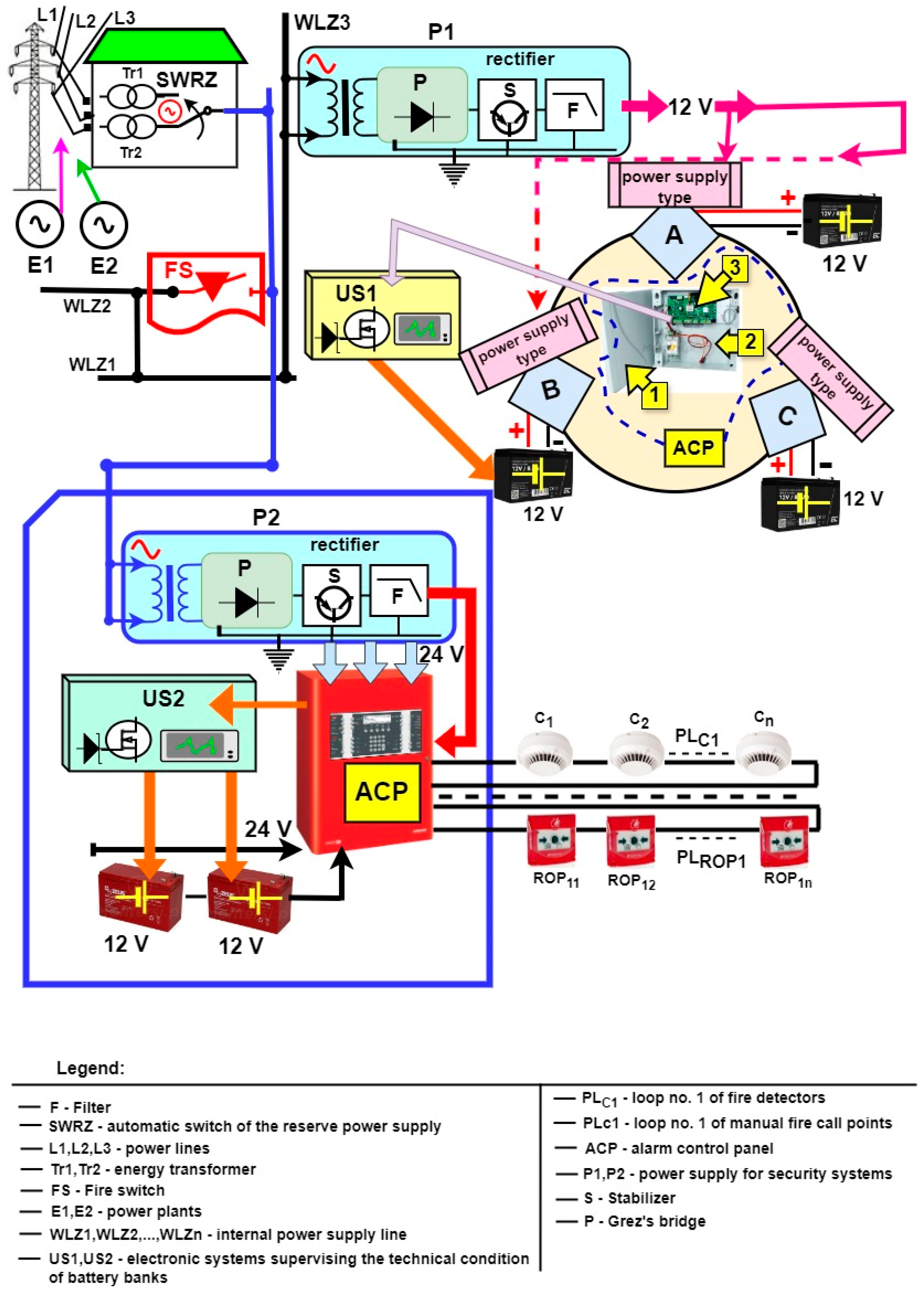
The correct functioning of all ESS elements (detectors) and devices (modules) requires a power supply with the use of an industrial grid. Figure 2 shows a simplified ESS power supply diagram and the use of two different power plants (E1, E2) supplying electricity via a three-phase power line—L1, L2 and L3 phase cables. In the event of a failure within these power circuits, an autonomous backup power switch (ABPS) automatically switches the power supply from E1 to E2 or E2 to E1 [2,6,9]. All ESS elements and devices are powered with a voltage equal to 12 V. An exemption is the FAS, which, upon start-up, consumes significant power equal to 24 V (voltage drop on detection circuits) due to the equipment employed (e.g., smoke dampers). Internal power lines (IPL) found in buildings contain a so-called fire switch (FS)—Figure 2, which isolates power supply voltage from the entire building, except for FAS. This system also functions during a fire, and the power supply voltage is safe for people participating in the fire-fighting process. In the course of a fire, PSP officers are able to preview all events (controls) at the ACR level and can also individually implement—force-specific switching, participating in the fire-fighting operation [1,7,10]. Power supply, alternating voltage from an industrial grid within an ESS is then subjected to rectification in P1 and P2 rectifiers assigned and monitored by (diagnostic modules—US1, US2) via the appropriate ACU of a given SS. A battery bank (BB) is connected to each power supply device that is an integral part of an ACU, usually encased in a metal cabinet. The BB constitutes a backup power source in the event of an E1 or E2 power supply malfunction [2,4,11]. BB capacities are determined based on the energy balance that takes into account current consumption for two ESS operating states (monitoring and alarming) and a specific time to ensure the functionality of these SS within these distinguished use scenarios—Figure 2.
Intrusion detection systems (IDS) employ different types of power supply devices (A,B,C) and systems supporting the battery bank charging process—Figure 2 [1,4,5]. In a C-type power supply device, the primary electricity source to power ESS is always a battery bank. Such a power supply type is most usually employed in the case of mobile means of transport—e.g., cars [3,8,12]. Whereas, in the case of other security systems and an ACU itself (designation No. 3 in Figure 2), there are two different technical solutions applied, namely, A- and B-type power supplies. Batteries for an entire ESS are hooked-up via two power cables (designation 2 in Figure 2), and the entire ACU, together with a backup power source, is encased in a metal cabinet (designation 1 in Figure 2). Contacts are monitored by the alarm control unit. An ESS power supply device is equipped with a rectifier, most usually a Graetz bridge, an output voltage stabilizer and a filter to attenuate undesired variable components of direct voltage [2,4,13,14]. A-type power supply devices (primary and backup power supply) are controlled and periodically charged by an IDS. In such a system, a primary power supply device employs a common industrial grid and 230 V alternating current to generate direct current. In turn, a BB backup power supply is powered via the IDS. A B-type power supply device also contains a primary system and a backup power supply—BB. However, in such a case, the BB is powered by an IDS power source [1,2,6].

2. Literature Review

An issue crucial in terms of the ESS operation process is the provision of power from an industrial grid, as well as ensuring the functionality of these systems during a malfunction (failure) of power supply from a power plant [2,15,16]. Issues related to the quality of electricity and the reliability of continuous electricity provisions from a consumer are yet another important problem associated with power supply—an ESS power supply device in this case. ESS power supply devices have expanded anti-interference filters and stabilizers monitored by microprocessor systems [1,3,17]. ESS operation can be thermally controlled via a thermistor. In such a case, the information on dangerous temperature fluctuations sent from a thermistor, resulting from, e.g., an overload, is sent to a microprocessor system monitoring the operation of the entire device. After appropriate analysis of the load signal, the microprocessor system adjusts the functioning of the entire power supply device by controlling appropriate system parameters—e.g., a stabilizer [4,18]. Due to the possible occurrence of harmonics, overvoltage, decays, as well as conducted and radiated interference in a power grid, modern power supply devices are additionally equipped with filtration systems (low-pass filters), both on the input and output sides of the system [1,19,20]. To limit the action of power supply systems on digital ACU systems, the power supplies least resistant to radiated interference are usually shielded by a metal guard made of a material exhibiting high magnetic permeability, which is characterized by high attenuation for the low-frequency range—up to 100 kHz [2,21,22]. Individual power supply device elements that operate under pulsed electricity processing are the sources of such interference. The article does not discuss issues related to electromagnetic interference and its impact on the operation of ESS components [14,23]. The authors focused on the second key issue, namely, power supply operational reliability, including BB [1,24,25]. The authors conducted operational tests of power supply employed in reality within ESSs that enable determining operation process indices—i.e., failure rate λ and recovery μ (repair) rate [2,26,27].
Particular attention within the ESS operation process—power supplies and backup power sources, namely, battery banks—should be paid to the parameters of the environment such devices are operated within [2,28,29]. All environmental parameters impact the operation of electronic elements and battery banks; however, the operating temperature is the value that determines durability, construed as operating reliability [1,30,31]. The BB operating durability parameters are also defined by the IEC 60050-482:2004 standard [32] and are understood as a period of correct BB functioning within the scope set out by the standard [2,33,34]. However, most manufacturers stipulate the battery bank’s theoretical service life, which is the outcome of a simulation, albeit without setting out experiment conditions [1,35]. Another important BB-related parameter is the service life defined in discharge cycles. BBs in an ESS usually operate in a buffer mode. Gel batteries often employed within ESSs are, owing to excess of electrolyte, resistant to deep discharge and can regenerate even after four weekly short-circuits (UL test) [2,36,37]. The self-discharge process is a considerable BB operational issue [1,38,39]. SLA battery banks employed in ESS are characterized by a low discharge coefficient owing to eliminating antimony (calcium alloy) from the plates and binding the electrolyte [4,40,41]. However, the BB (for SLA) self-discharge degree is a function of its operating temperature, and the limit operating temperature is +55 °C [3,42,43]. The authors of the paper studied power supply devices located in building rooms, where the temperature has always been stabilized by heating systems and did not exceed the maximum value in the range of (+10–24) °C [1,44,45]. Therefore, in the course of establishing the operational reliability of power supply systems, this environmental parameter was not taken into account when determining λ failure rate and μ recovery rate [3,46,47]. However, at a further stage of their research, the authors are planning to determine the aforementioned operating parameters for other operating temperatures of power supply devices employed at other, even extreme temperatures—for C-type power supply devices [1,3,24,48].
Throughout the entire complex operation process, power supply systems require continuous, real-time diagnostic processes of their technical states [2,29,49,50]. An alarm control unit in an ESS is always responsible for diagnosing power supply systems [51,52]. Because an ACU also diagnoses detection loops and circuits, signal transmission devices, and all devices hooked-up to input ports, most modern solutions applicable to such equipment involve an additional microprocessor for monitoring this process only [1,53,54]. In older ESS solutions, the maintenance staff was able to read BB voltage source parameters on the encoder LCD panel. [55,56]. All ESS diagnostic processes are always implemented concurrently with sensor working signals [57,58,59]. At the same time, the diagnostic process implementation time and period depend on the operators [3,60]. All diagnostic information on power supply systems is available on the ACU panel while being additionally sent to an ARC [4,61,62]. However, in the case of contemporary ESS diagnostic processes, the maintenance team does not have information on the technical states of redundant components [2,25,63,64]. In the development of an operation process model for power supply systems and in conducting the FAS operation process computer simulation, the authors suggest employing real-time information to assess the impact of power supply device unfitness on the R(t) reliability of the entire system [2,10,65,66].
The element that determines the detection of a security hazard is always a detector with a built-in sensor responding to various physical values of the environment it is located [67,68,69]. This includes, e.g., smoke, temperature, electromagnetic radiation, motion, broken glass, etc. [70,71,72]. The correct operation of all ESS elements and devices within a given environment involves, in addition to permissible, e.g., temperature changes also the rated supply voltages set out by manufacturers [4,73,74]. Supply voltage changes, fluctuations or oscillations significantly impact the correct operation of these elements [25,27,75]. Supply voltage fluctuations or oscillations lead to a change in the operating points of active elements, making up all detectors and the ACU [2,28,29,76]. Therefore, the stabilization of supply voltage occurring within detection and transmission circuits that the detectors are hooked-up to is such an important issue [30,63,70]. The authors of the paper did not research the impact of a supply voltage change on ESS functioning (its individual elements) [77,78,79]. However, ESS supply system reliability is also a crucial operational issue, e.g., the determination of permissible supply voltage changes [1,80,81,82].

3. Selected Operation Process Graphs for Electronic Security Systems Operated in Buildings and State Critical Infrastructure Facilities

Because of their varying internal functional structure, including the functions implemented in relation to ensuring the security of the monitored facilities and vast areas of state critical infrastructure (SCI), ESS can be divided into three groups in terms of ensuring power supply [1,2,79]. Essentially, this division in relation to ESS power supply takes into account the volume (area expressed in m2), and the area extensiveness of facilities constituting parts of SCI. Three different technical structures of ESS power supply can be distinguished:
  • Focused power supply type. It is the simplest technical structure; in this case, an ACU or FACU acts as a power source for all elements and devices within transmission mains, as well as detection loops and circuits for the FAS. The start and end of such detection loops, circuits or mains are always located at an alarm control unit, which also houses a power supply with a specific current efficiency and a BB monitored by an ACU or FACU diagnostic module [3,16,73];
  • Distributed power supply type. This is a technically complex infrastructure. The ACU or FACU, together with their built-in internal power supply devices, act as a vast power supply system for all ESS elements and devices. In such a case, each ACU or FACU has its own power supply, BB and diagnostic module monitoring backup power parameters. A supply power balance is determined for each ESS subsystem of the distributed structure separately, while their total value specifies the total electricity demand. In the event of a power supply or BB malfunction within a single ESS subsystem, the next nearest security system cannot supply (be a power source) the damaged facility. All ACUs and FACUs are connected in a single or double loop, a star or a double main via a transmission circuit (fiber-optic line). Diagnostic information on the power supply of individual ESS subsystems within a given facility can be sent to an alarm receiving center (ARC) or be locally monitored at every ACU or FACU LCD panel. However, the start and end of detection loops, circuits or mains must always be located at a given ACU or FACU. The aforementioned detection loops or circuits, because of their power supply and the implementation of the security function, cannot be shared by individual ESS subsystems [2,7,33,83];
  • Mixed-type ESS power supply. It is always a technical combination and power supply solution for two previously presented structures. The focused power supply system is implemented for the most important of the protected facilities, implementing and ensuring security [1,84,85].
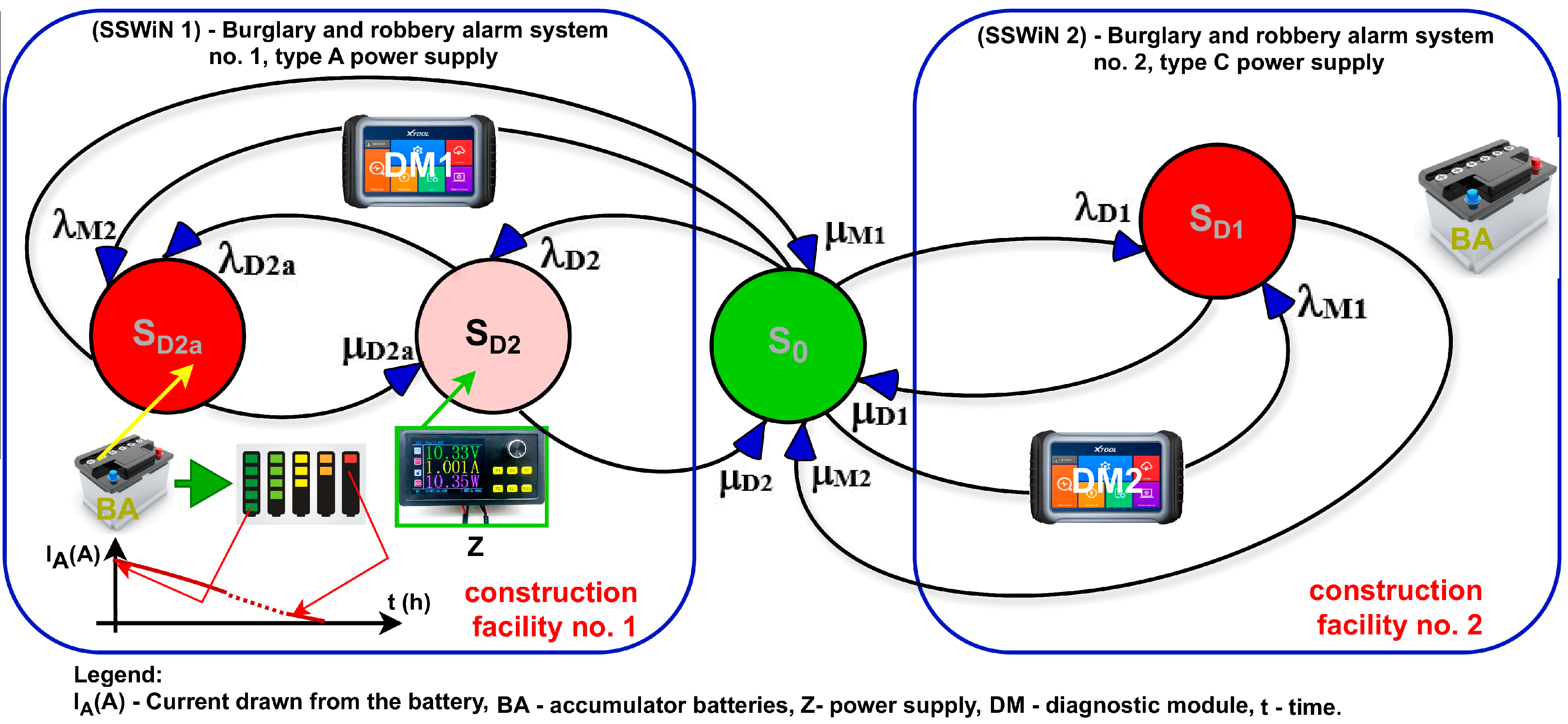
Figure 3 and Figure 5 illustrate power supply system operation process graphs for two different technical structures of security systems monitoring these facilities. Figure 3 shows a power supply process graph for an integrated security system operated in two buildings, No. 1 and 2. These buildings employ two different security subsystems—i.e., intrusion detection systems (IDS). Building No. 1 operates an A-type power supply device. An overhead industrial power supply line is routed to this building. Whereas, the remote building No. 2, which houses fuel and lubricant storage, also employs IDS No. 2, albeit with a C-type power supply device. Such a technical organization of security systems is determined by the high distance of building No. 2 from the ARC and the power supply line. Building No. 2 employs a C-type power supply device, also for legal reasons. Due to local land development conditions, it is impossible to provide power for both the overhead and underground industrial power supply lines. IDS No. 1 and 2, owing to the technical structure, involves DM1 and DM2 diagnostic models intended for monitoring output voltages and currents—in power supply devices drawn from the battery bank. Information on BB state is automatically and wirelessly sent by diagnostic module No. 2 to the ARC, where a 24/7 maintenance team that monitors the IDS No. 1 and 2 operation process is located. Information on power consumption from the BB and the BB output voltage level is automatically sent to the ARC—maintenance team [1,50,75]. The capacity of the BB located in building No. 1 is determined using the energy balance. Whereas the BB located in building No. 2 ensures the functionality of the IDS, DM2 diagnostic module and the alarm and failure signal wireless transmission device for at least a week. Building No. 2 also houses a backup battery bank, automatically activated in the event of a malfunctioning primary power supply unit. Figure 3 does not show this technical solution for legibility’s sake. In the case of IDS No. 1, the system has its own local switching station for power supply from an industrial grid, while the power supply devices are always in the ACU and are always monitored for protection against sabotage by a relay contact [2,54,86,87]. Also, the BB within this system is located in a metal cabinet, together with an ACU. The capacity of the BB in IDS No. 1 is based on the energy balance and takes into account monitoring and alarming times specified in the standards for such security system types.
The systems illustrated in Figure 3 were described by the following system of Kolmogorov–Chapman Equation (1):
R 0 ( t ) = λ D 1 · R 0 ( t ) + μ D 1 · Q D 1 ( t ) λ M 1 · R 0 ( t ) + μ M 2 · Q D 1 ( t ) λ D 2 · R 0 ( t ) + μ D 2 · Q D 2 ( t ) λ M 2 · R 0 ( t ) + μ M 1 · Q D 2 a ( t ) , Q D 1 t = λ D 1 · R 0 t μ D 1 · Q D 1 t + λ M 1 · R 0 t μ M 2 · Q D 1 t , Q D 2 t = λ D 2 · R 0 t μ D 2 · Q D 2 t λ D 2 a · Q D 2 ( t ) + μ D 2 a · Q D 2 a ( t ) , Q D 2 a t = λ M 2 · R 0 t μ M 1 · Q D 2 a t + λ D 2 a · Q D 2 t μ D 2 a · Q D 2 a ( t ) .
The following initial conditions (2) were adopted for further analysis:
R 0 ( 0 ) = 1 , Q D 1 0 = Q D 2 0 = Q D 2 a 0 = 0 .
Next, applying the Laplace transform enabled obtaining the following system of linear Equation (3):
s · R 0 * s 1 = λ D 1 · R 0 * s + μ D 1 · Q D 1 * s λ M 1 · R 0 * s + μ M 2 · Q D 1 * s λ D 2 · R 0 * s + μ D 2 · Q D 2 * s λ M 2 · R 0 * s + μ M 1 · Q D 2 a * s , s · Q D 1 * s = λ D 1 · R 0 * s μ D 1 · Q D 1 * s + λ M 1 · R 0 * s μ M 2 · Q D 1 * s , s · Q D 2 * s = λ D 2 · R 0 * s μ D 2 · Q D 2 * s λ D 2 a · Q D 2 * s + μ D 2 a · Q D 2 a * s , s · Q D 2 a * s = λ M 2 · R 0 * s μ M 1 · Q D 2 a * s + λ D 2 a · Q D 2 * s μ D 2 a · Q D 2 a * s .
Further transformations led to obtaining probabilities for the system presented in Figure 3 to remain in a distinguished state in symbolic terms (Laplace) (4):
R 0 * s = μ D 2 a · μ D 1 μ M 2 s · λ D 2 a · μ D 2 a λ D 2 a + μ D 2 + s μ D 2 a + μ M 1 + s λ M 2 · μ D 2 a + λ D 2 · μ D 2 a + μ M 1 + s · μ D 2 · μ D 2 a · μ D 1 + μ M 2 + s + μ M 1 · λ D 2 a + μ D 2 + s · μ D 1 + μ M 2 + s + λ D 2 a · μ D 2 a λ D 2 a + μ D 2 + s · μ D 2 a + μ M 1 + s · λ D 2 · μ M 1 · μ D 1 + μ M 2 + s μ D 2 a · λ D 1 λ M 1 μ D 1 μ M 2 + λ D 1 + λ D 2 + λ M 1 + λ M 2 + s μ D 1 + μ M 2 + s ,
The determined relationship (4) enables calculating the probabilities of the system in question staying within a distinguished state.
With the use of computer assistance, it is possible to conduct calculations enabling the determination of the probability value for the system in question to be in a state of full fitness S0. Such a sequence of actions is shown in Example 1.
Example 1.
Let us assume the following values describing the analyzed system [1,7,11,25,60]:
  • Research duration—1 year (the value of this time is given in the units as hours [h]):
    t = 8760   h
  • Intensity of transition λD1:
    λ D 1 = 0.8 · 10 7   1 h ,
  • Intensity of transition λM1:
    λ M 1 = 0.8 · 10 6   1 h ,
  • Intensity of transition µD1:
    μ D 1 = 0.25   1 h ,
  • Intensity of transition µM2:
    μ M 2 = 0.5   1 h ,
  • Intensity of transition λD2:
    λ D 2 = 0.8 · 10 7   1 h ,
  • Intensity of transition λM2:
    λ M 2 = 0.8 · 10 6   1 h ,
  • Intensity of transition µD2:
    μ D 2 = 0.25   1 h ,
  • Intensity of transition µM1:
    μ M 1 = 0.5   1 h ,
  • Intensity of transition λD2a:
    λ D 2 a = 0.8 · 10 7   1 h ,
  • Intensity of transition µD2a:
    μ D 2 a = 0.25   1 h .
The following is obtained for the above input values using Equation (4):
R 0 * s = 0.140625 + 0.9375 · s + 1.75 · s 2 + s 3 0.140626 · s + 0.937502 · s 2 + 1.75 · s 3 + s 4 ,
The following is obtained through subsequent transformations:
R 0 t = 0.999996 + 1.70668 · 10 6 · e 0.750001 · t + 1.91999 · 10 6 · e 0.250001 · t .
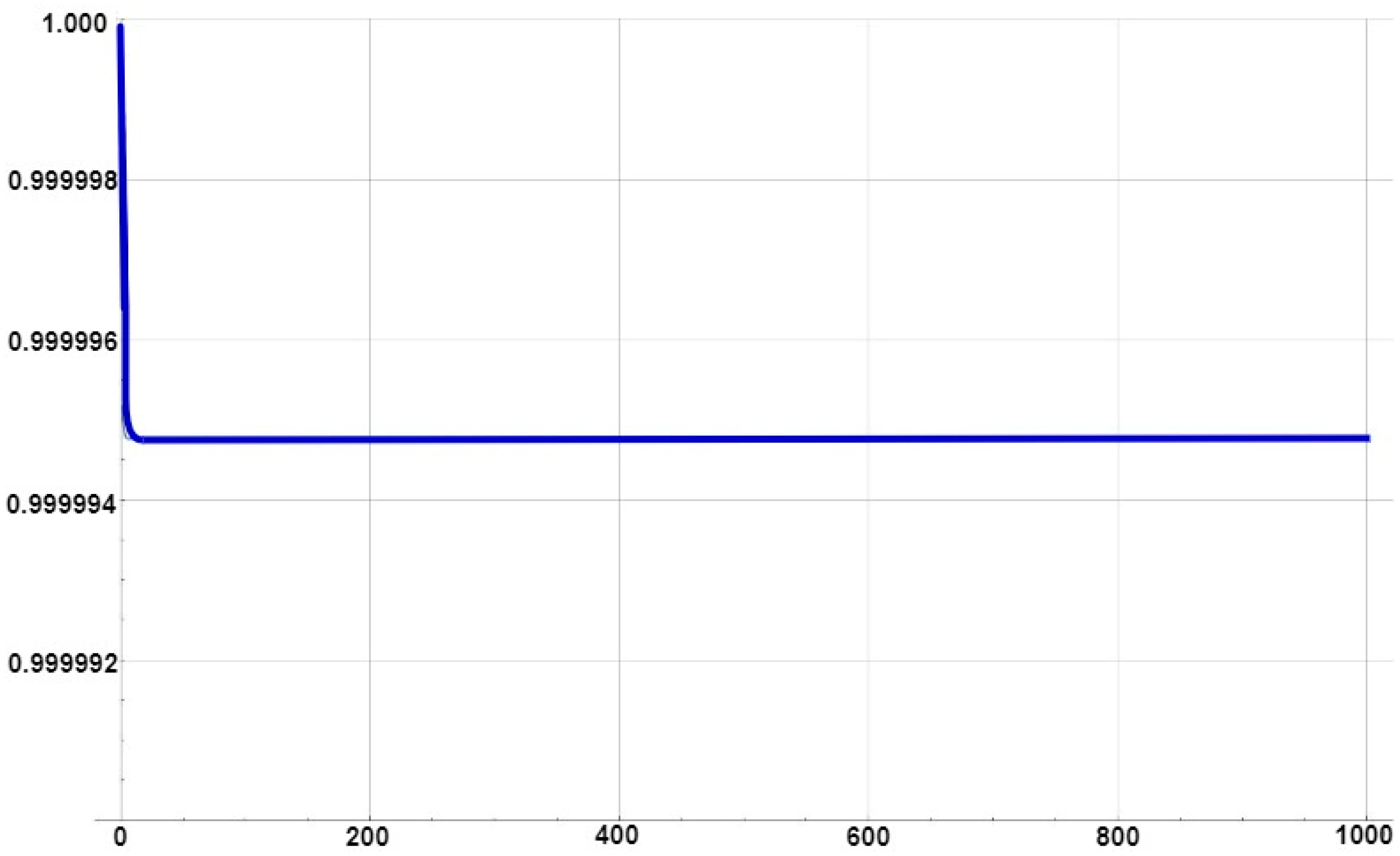
Figure 4 shows a depiction of a probability function waveform related to an ESS staying in a state of full fitness.
The presented reliability and operational system analysis enables comparing different types of maintenance activities aimed at their rationalization.
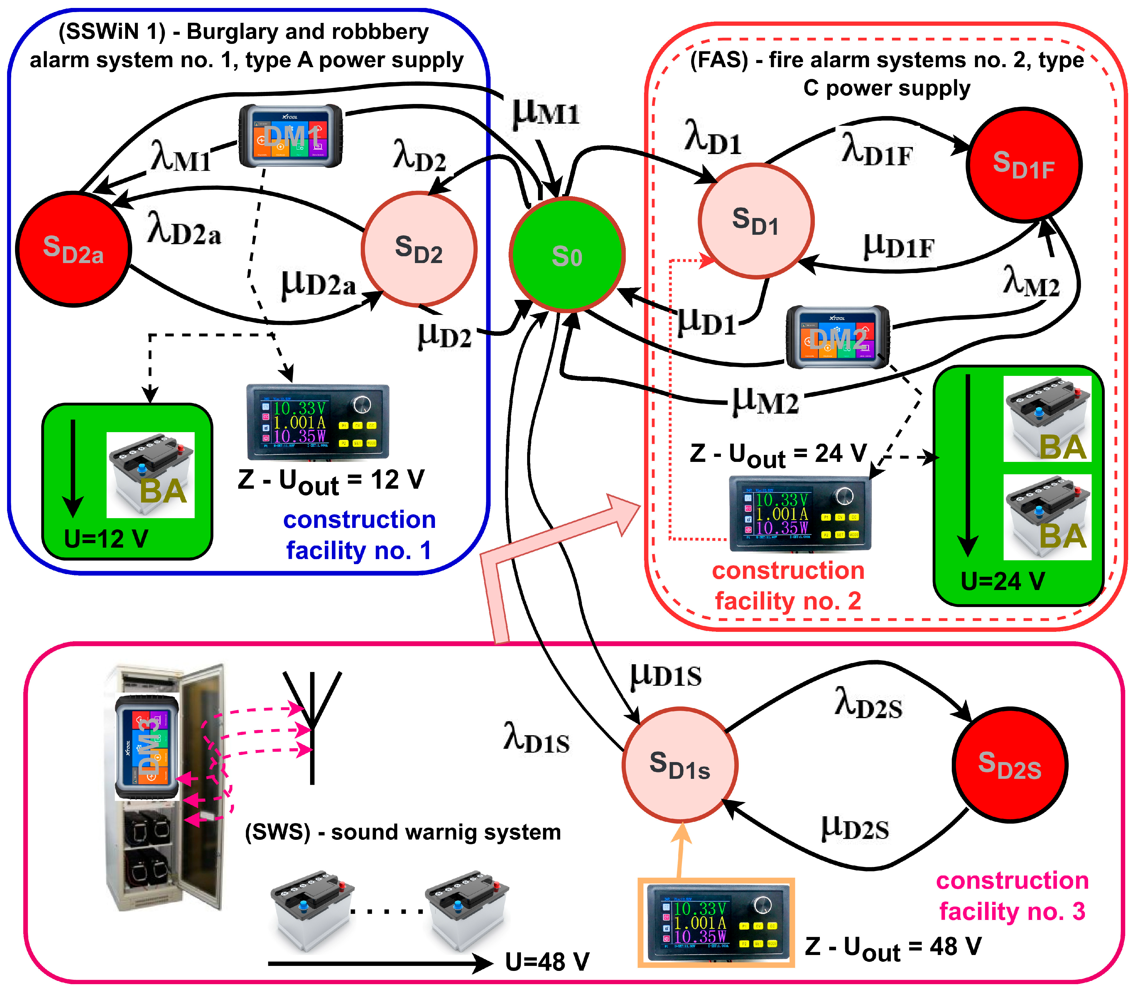
Figure 5 illustrates a power supply operation process graph for security systems located over a vast state critical infrastructure area. There are three different ESSs employed in this case, due to requirements of protecting the entire area. All security systems, including power supply, required for the operation of these technical facilities are constantly diagnosed. Diagnostic information on the technical state of rated voltages and currents flowing in the internal and external circuits of security systems is processed in alarm control units by a microprocessor intended solely for such tasks (diagnostic process) [5,36,88,89]. Diagnostic information from the alarm control unit is transmitted via two independent ICT routes (for reliability-related reasons) to an Alarm Receiving Centre (all working signals occurring within the ESS, corresponding to the monitoring, alarming and failure technical states). Whereas the employed fire alarm signal additionally sends an alarm (fire) signal to the State Fire Brigade (PSP) and monitoring law enforcement services—responsible for enforcing the law within protected facilities and affiliated areas—e.g., transportation [1,71,90,91]. All ESSs are monitored and operated by a 24/7 maintenance team located at the ARC. The FAS employed together with an Audio Warning System (AWS) employed within the operation process at this SCI facility, pursuant to legislation applicable in Poland, cannot be integrated with other ESS—e.g., IDS. In the use of FAS and WS within these buildings and over a vast area, it is only possible to exchange information between individual security systems; however, it is impossible to control them locally and remotely [2,29,92]. All ESSs are powered from an industrial power grid and have their own backup power source; in this case these are battery banks shown in Figure 5.
Figure 5. Power supply operation process graph for three different ESSs employed in buildings and over a vast appurtenant area. The designations found in the Fig. are explained in the key. The AWS is triggered by the FAS, as presented in the Fig. in a simplified way. Security systems employ different supply voltage values—IDS—12 V, FAS—24 V, and AWS—48 V.
Energies 17 03665 g005
Each system separately has its own power supply module with a specific current efficiency and a diagnostic module located in the alarm control unit, which monitors working voltage and currents found within individual ESS transmission mains, loops and circuits—Figure 5. Different voltages supplying individual security systems (12, 24 and 48 V) arise from working—rated currents drawn by individual ESS elements—e.g., smoke damper control modules and partition door electromechanical locks—fire zones found in individual buildings (FAS) or power amplifiers with processing employed as part of an AWS, e.g., D-class amplifiers with digital sound processing (DSP) and output voltage equal to 100 V (output signal with a power of, e.g., 1000 W RMS) [1,14,37,93]. An AWS is employed only in buildings No. 2, together with a FAS. Under the monitoring technical state, the elements, modules and devices for all ESSs shown in Figure 5 are powered by their own power sources, constituting the equipment of each individual system—Figure 5. System-integrated power supply devices are monitored by diagnostic modules (DM 1,2,3) that are most often additional equipment for all ACUs. Diagnostic information on the power supply technical state is forwarded to an ARC. At the same time, all battery banks found within an ESS are also diagnosed in real time under all operating states of these security systems. A change in the output voltage below a preset level is reported to the ACU and ARC. The AWS (Figure 5) employs the DM3 diagnostic module encased in a metal cabinet, which also houses BBs. In this case, a BB technical state diagnostic signal is wirelessly sent to the ACU AWS (Figure 5). If all ESSs demonstrated in Figure 5 are fit, they remain in the S0 operational state, which in most cases is the security system monitoring state [2,70,74,94]. Industrial power supply unfitness causes a transition from the S0 technical state to the respective technical state of individual subsystems SD1, SD2 and SD1S at a respective failure rate—λD1, λD2 and λD1S. After the occurrence of this technical state, it is possible to implement service activities (repair) of individual power supply modules at a recovery rate of—μD1, μD2 and μD1S, respectively (Figure 5). Failure to undertake repair results in an automatic transition of all ESS to the backup power supply at a failure rate of λD1F, λD2a and λD2S. If a maintenance team does not take any recovery actions, individual ESS switches to the state of security unreliability (unfitness)—reaching the states marked in red, SD2a (IDS), SD1F (FAS) and SD2S (AWS). For technical reasons, it is impossible in the case of ESS for a power supply failure at time t0 in all systems simultaneously [1,3,33,95]. The occurrence of an atmospheric discharge within a protected area or a power line overvoltage does not cause the transition of all ESS to the state of security unreliability due to the overvoltage protections in the industrial power supply line main external and internal circuits. ESSs employ multi-stage power supply system protections against an atmospheric discharge pulse and surges, as well as overvoltages in overhead and underground lines [2,4,65,96].
The systems illustrated in Figure 5 were described by the following system of Kolmogorov–Chapman Equation (5):
R 0 t = λ D 1 · R 0 t + μ D 1 · Q D 1 t λ M 2 · R 0 t + μ M 2 · Q D 1 F t λ D 2 · R 0 t + μ D 2 · Q D 2 t λ M 2 · R 0 t + μ M 1 · Q D 2 a t λ D 1 S · R 0 ( t ) + μ D 1 S · Q D 1 S ( t ) , Q D 1 t = λ D 1 · R 0 t μ D 1 · Q D 1 t λ D 1 F · Q D 1 t + μ D 1 F · Q D 1 F t , Q D 1 F t = λ M 2 · R 0 t μ M 2 · Q D 1 F t + λ D 1 F · Q D 1 t μ D 1 F · Q D 1 F t , Q D 2 t = λ D 2 · R 0 t μ D 2 · Q D 2 t λ D 2 a · Q D 2 ( t ) + μ D 2 a · Q D 2 a ( t ) , Q D 2 a t = λ M 2 · R 0 t μ M 1 · Q D 2 a t + λ D 2 a · Q D 2 t μ D 2 a · Q D 2 a t , Q D 1 S t = λ D 1 S · R 0 t μ D 1 S · Q D 1 S t λ D 2 S · Q D 1 S t + μ D 2 S · Q D 2 S ( t ) , Q D 2 S t = λ D 2 S · Q D 1 S t μ D 2 S · Q D 2 S ( t ) .
The following initial conditions (6) were adopted for further analysis:
R 0 ( 0 ) = 1 , Q D 1 0 = Q D 1 F 0 = Q D 2 0 = Q D 2 a 0 = Q D 1 S 0 = Q D 2 S 0 = 0 .
Next, applying the Laplace transform enabled obtaining the following system of linear Equation (7):
s · R 0 * s 1 = λ D 1 · R 0 * s + μ D 1 · Q D 1 * s λ M 2 · R 0 * s + μ M 2 · Q D 1 F * s λ D 2 · R 0 * s + μ D 2 · Q D 2 * s λ M 2 · R 0 * s + μ M 1 · Q D 2 a * s λ D 1 S · R 0 * s + μ D 1 S · Q D 1 S * s , s · Q D 1 * s = λ D 1 · R 0 * s μ D 1 · Q D 1 * s λ D 1 F · Q D 1 * s + μ D 1 F · Q D 1 F * s , s · Q D 1 F * s = λ M 2 · R 0 * s μ M 2 · Q D 1 F * s + λ D 1 F · Q D 1 * s μ D 1 F · Q D 1 F * s , s · Q D 2 * s = λ D 2 · R 0 * s μ D 2 · Q D 2 * s λ D 2 a · Q D 2 * s + μ D 2 a · Q D 2 a * s , s · Q D 2 a * s = λ M 2 · R 0 * s μ M 1 · Q D 2 a * s + λ D 2 a · Q D 2 * s μ D 2 a · Q D 2 a * s . s · Q D 1 S * s = λ D 1 S · R 0 * s μ D 1 S · Q D 1 S * s λ D 2 S · Q D 1 S * s + μ D 2 S · Q D 2 S * s , s · Q D 2 S * s = λ D 2 S · Q D 1 S * s μ D 2 S · Q D 2 S * s .
Further transformations led to obtaining probabilities for the systems presented in Figure 3 to remain in distinguished states in symbolic terms (Laplace) (8):
R 0 * s = μ D 1 F · μ D 2 a · λ D 2 s · μ D 2 s λ D 2 s + μ D 1 s + s · μ D 2 s + s · λ D 2 a · μ D 2 a λ D 2 a + μ D 2 + s · μ D 2 a + μ M 1 + s · λ D 1 F · μ D 1 F λ D 1 F + μ D 1 + s · μ D 1 F + μ M 2 + s λ M 2 · μ D 1 F + λ D 1 · μ D 1 F + μ M 2 + s · μ D 1 · μ D 1 F · μ D 2 a · λ D 2 s · μ D 2 s λ D 2 s + μ D 1 s + s · μ D 2 s + s · λ D 2 a · μ D 2 a λ D 2 a + μ D 2 + s · μ D 2 a + μ M 1 + s + μ D 2 a · μ M 2 · λ D 1 F + μ D 1 + s · λ D 2 s · μ D 2 s λ D 2 s + μ D 1 s + s · μ D 2 s + s · λ D 2 a · μ D 2 a λ D 2 a + μ D 2 + s · μ D 2 a + μ M 1 + s + λ D 1 F · μ D 1 F λ D 1 F + μ D 1 + s · μ D 1 F + μ M 2 + s · λ D 1 · μ D 2 a · μ M 2 · λ D 2 s · μ D 2 s λ D 2 s + μ D 1 s + s · μ D 2 s + s · λ D 2 a · μ D 2 a λ D 2 a + μ D 2 + s · μ D 2 a + μ M 1 + s μ D 1 F · λ M 2 · μ D 2 a + λ D 2 · μ D 2 a + μ M 1 + s · μ D 2 · μ D 2 a · λ D 2 s · μ D 2 s λ D 2 s + μ D 1 s + s · μ D 2 s + s μ M 1 · λ D 2 a + μ D 2 + s · λ D 2 s · μ D 2 s λ D 2 s + μ D 1 s + s · μ D 2 s + s + λ D 2 a · μ D 2 a λ D 2 a + μ D 2 + s · μ D 2 a + μ M 1 + s · λ D 2 · μ M 1 · λ D 2 s · μ D 2 s λ D 2 s + μ D 1 s + s · μ D 2 s + s μ D 2 a · λ D 1 s · μ D 1 s · μ D 2 s + s λ D 1 + λ D 1 s + λ D 2 + 2 · λ M 2 + s · λ D 2 s · μ D 2 s λ D 2 s + μ D 1 s + s · μ D 2 s + s ,
The determined relationship (8) enables calculating the probabilities of the system in question staying within a distinguished state.
With the use of computer assistance, it is possible to conduct calculations enabling the determination of the probability value for the system in question to be in a state of full fitness S0. Such a sequence of actions is shown in Example 2.
Example 2.
Let us assume the following values describing the analyzed system [1,7,11,25,60]:
  • Research duration—1 year (the value of this time is given in the units as hours [h]):
    t = 8760   h
  • Intensity of transition λD1:
    λ D 1 = 0.8 · 10 7   1 h ,
  • Intensity of transition λM1:
    λ M 2 = 0.8 · 10 6   1 h ,
  • Intensity of transition µD1:
    μ D 1 = 0.25   1 h ,
  • Intensity of transition µM2:
    μ M 2 = 0.5   1 h ,
  • Intensity of transition λD1F:
    λ D 1 F = 0.8 · 10 7   1 h ,
  • Intensity of transition µD1F:
    μ D 1 F = 0.25   1 h ,
  • Intensity of transition λD2:
    λ D 2 = 0.8 · 10 7   1 h ,
  • Intensity of transition λM2:
    λ M 2 = 0.8 · 10 6   1 h ,
  • Intensity of transition µD2:
    μ D 2 = 0.25   1 h ,
  • Intensity of transition µM1:
    μ M 1 = 0.5 1 h ,
  • Intensity of transition λD2a:
    λ D 2 a = 0.8 · 10 7   1 h ,
  • Intensity of transition µD2a:
    μ D 2 a = 0.25   1 h ,
  • Intensity of transition λD1s:
    λ D 1 s = 0.8 · 10 7   1 h ,
  • Intensity of transition µD1s:
    μ D 1 s = 0.25   1 h ,
  • Intensity of transition λD2s:
    λ D 2 s = 0.8 · 10 7   1 h ,
  • Intensity of transition µD2s:
    μ D 2 s = 0.25   1 h .
The following is obtained for the above input values using Equation (8):
R 0 * s = 0.00219727 + 0.0410156 · s + 0.308594 · s 2 + 1.1875 · s 3 + 2.4375 · s 4 + 2.5 · s 5 + s 6 0.00219728 · s + 0.0410158 · s 2 + 0.308595 · s 3 + 1.1875 · s 4 + 2.4375 · s 5 + 2.5 · s 6 + s 7 ,
The following is obtained through subsequent transformations:
R 0 t = 0.999995 + 1.06633 · 10 6 · e 0.750001 · t + 7.42062 · 10 10 · e 0.75 · t 0.0000204268 · e 0.250141 · t + 0.0000878001 · e 0.250017 · t 0.000087666 · e 0.249984 · t + 0.0000201588 · e 0.24986 · t .
Figure 6 shows a depiction of a probability function waveform related to an ESS staying in a state of full fitness.
Similarly to Example 1, the reliability and operational system analysis enables comparing different types of maintenance activities aimed at their rationalization.

4. Miniature Fuse-Links as a Practical Embodiment of Element Redundancy Employed in Security System Power Supply Devices

Redundancy [97] that can adopt the following forms is employed as a measure to improve the reliability of a technical object or its overall operating conditions in power and electronic systems and circuits:
  • Structural— the implementation of appropriate technical object reliability structures (e.g., parallel with loaded reserve, so-called online or parallel with unloaded reserve, so-called off-line, k with n, etc.)—it also involves, e.g., employing a multi-detector sensor—optical for smoke, temperature and flame in a FAS, which detects various fire characteristic values;
  • Parametric—employing selected structural elements of a technical object with the technical properties that ensure parametric reserve other than would arise from, e.g., climatic operating conditions. For example, the use of electrolytic capacitors intended for operation under more demanding climate conditions—instead of an upper operating temperature limit of 85 °C, employing ones exhibiting the upper limit of the said parameter at a level of 105 °C, despite the fact that the analyses conducted at the system device or module engineering stage do not require this at all;
  • Functional—a technical object is composed of elements, with selected units that may implement (in addition to their intended ones) functions of other elements should they become unfit (using a CCTV camera able to count people entering and exiting the facility—it partially implements the access control function, providing information to the security system on, e.g., the number of users and customers remaining at a given time within the building).
  • Resistance-related—specified as the resistance of a technical object (its subassembly or a collection thereof) to loads adopted at the engineering stage while ensuring appropriate reserve (an example may be an electrolytic capacitor intended for continuous operation at a voltage of 25 [V], the short-term operation of which at a higher voltage, e.g., 30 [V] without detriment to this subassembly was enabled at the engineering and manufacturing stages);
  • Temporal—providing a technical object with a more favorable time interval (from the perspective of its operation) than, e.g., adopted by normative requirements (e.g., ensuring a longer operation time for the intrusion detection system using battery power in the event of a grid voltage decay, while simultaneously maintaining the requirements of appropriate battery charging time—ration between battery capacity and power supply current efficiency) provided for in the standard. Yet another example found in security systems is adopting a longer time for entering entrance/exit codes at the encoders, taking into account conditions associated, e.g., with age—wearing glasses, additional keyboard illumination, etc. [98];
  • Information-based—a technical object employing technical solutions that enable repeated (automatic or manual) measurement of the quantity of interest that should be subject to monitoring to ensure the credibility of thus obtained information (most electronic security systems continuously monitor the state of detection circuits to identify the operational states of alarming, failure, sabotage, etc.);
  • Element-based—a technical object is fitted with additional subassemblies or devices, the presence of which is not required for such an object to implement its intended task but favorably impacts its reliability.
Miniature fuse-links constitute measures to actively increase technical object reliability through element redundancy. Their presence (similar to spark gaps, varistors, TVSs, etc.) in electronic security systems is not required for them to implement their basic task of physical protection of human life/health and property; however, it significantly increases the reliability of these systems, given their large scope of responsibility compared to consumer-class electronic systems.
Employing miniature fuse-links in the backup power supplies of electronic security systems, besides satisfying the assumption of element redundancy due to the nature and functions distinguishing the electronic subassemblies in question, is also tantamount to using a so-called emergency subsystem. It is a specific case of anti-failure systems that form the ultimate layer of technical solutions, the sole objective of which is to completely or partially prevent a technical object failure or, in an extreme case, minimize losses when a destructive factor occurs.
The fuse-link operation comes down to protecting a circuit they are embedded in against the consequences of overload current flow (possibly being the result of short circuits, while practically it is almost always associated with a failure and a continuing transient state—resulting from, e.g., commutation phenomena or excessive circuit load that was not taken into account in the design of a given system or that exceeds its permissible technical parameters) [99]. If, due to one of the above-mentioned phenomena, an electric circuit experiences the flow of current with a value within the limits of overload current, this triggers the process of fiber melting inside a fuse-link, which consequently leads to circuit opening and breaking (de-energization). This leads to a decaying flow of current with uncontrolled intensity. Fuse-link fiber, which is the most important element of a miniature fuse, is nothing else than a metal wire made of an alloy that is a combination of steel, nickel and/or copper with a strictly specified cross-section shape.
The tcb circuit breaking time should be considered the most important parameter of the analyzed components. Its significance is more evident when we learn the response of the elements in question to an action of overload character, where two stages can be distinguished. As overcurrent appears in the circuit (or its fragment) protected by a given fuse-link, leading to the occurrence of electricity losses in the fuse-link fiber, which manifests its presence in the form of radiated Joule heat until it is discontinued due to the aforementioned phenomena, the first stage called the tp pre-arcing time remains. It is crucial to remember that the highlighted process is not equivalent to the decay of current flow through fuse-links and, hence, within the protected circuit. It is still supported by the present electric arc, attempting to “bind” the most important fuse element anew, which was disintegrated due to melting. The interval between the moment of discontinuing fuse-link fiber and the arcing decay (equivalent to total cessation of the electrical current flowing in the branch of the circuit subject to fuse-link protection) forms the definition of the tł arcing time.
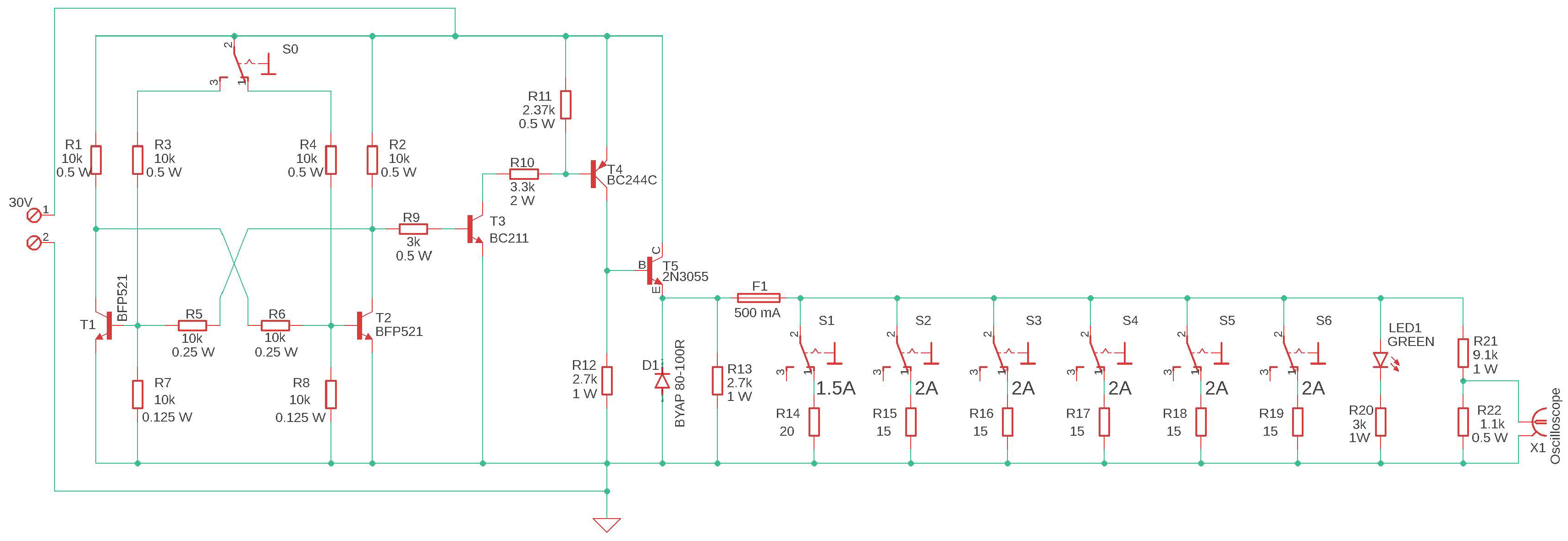
It is hard not to notice the potential impact of the said miniature fuse-link parameter on the reliability of the element or module making up an electronic system of technical protections wherein they will be employed. Therefore, it can be concluded that, from the perspective of playing the role of an emergency reliability system, fuse-links are distinguished by a certain protection potential. Given the fact that the electronic subassemblies in question, with theoretically the same most important technical parameters, are made by different manufacturers through individual processes and using materials that the specific composition of which fully constitutes company secret, it may be assumed that applying a repeated research methodology and an overcurrent of repeated nature to measure the tcb circuit breaking time would provide different results for products offered by different manufacturers. Such measurements are made possible by the measuring add-on developed at the Faculty of Electronics of the Military University of Technology in Warsaw, supported by a two-channel digital oscilloscope and a laboratory power supply. Figure 7 displays a schematic diagram of the measuring add-on referred to above.
The resistance values of the resistors making up the load system were selected so that overload current with a specified intensity flows through the tested fuse after individual subassemblies are added to the circuit. As a result, the developed add-on offers selected discrete values of fuse-link overload current (activated through specially designed switches), falling in the range from approx. 1.5 to approx. [A] (both extremes inclusive). For the operating principle applicable to these devices to be better understood, the activity will be explained on the example of a 5.5 [A] overload current. In the case in question, it is necessary to hook-up output circuit with the T5 transistor operating as a key for a single resistor triggering the flow of 1.5 [A] current (activated by the S1 switch), as well as two resistors forcing a 2.0 [A] current each (switching two random levers from S2 to S6). A destructive test is triggered by changing the transistor state in the R-S bistable flip-flop. This function is globally initiated by the S0 switch. Employing the analyzed component ensures the correct addition of the tested resistive load fuse to the circuit, leading to the flow of current exhibiting the expected intensity. Commissioning the said task to an operator would have to lead to an expectation that the actual value of the current flowing through the tested fuse-link could not be determined. It is highly unlikely for the experimenter to be able to add all elements making up the load using switches (the test add-on is equipped with more than one) in a perfectly synchronous manner and using the same force in each case. The employed solution also provides full control over the test start time and minimizes the risk of accidental measurement initiation. Good engineering practice at test benches of this type is taking into account any visual form of signaling destructive test triggering (activation of the fuse-link in the case in question). The discussed add-on also provides for such a system. It was implemented based on an LED 1 (Light Emitting Diode) and resistor R20. In addition, the load voltage is drawn via a resistant voltage divider—elements R21 and R22. The second one is fitted with a signal socket for connecting the first oscilloscope channel via a co-axial cable of the laboratory pin type (inf. banana plug)—BNC to record the time waveform of the voltage that determines the tcb circuit breaking time of the tested fuse-link.
The tests involved fuse-links distinguished by the following technical parameters:
Operating characteristics: quick-acting—F (Ger. flink);
Type: miniature;
Rated current: 500 [mA].
Dimensions (diameter x length): 5 × 20 [mm];
Body material: glass;
Filler type: none—no quenching agent (lower breaking capacity);
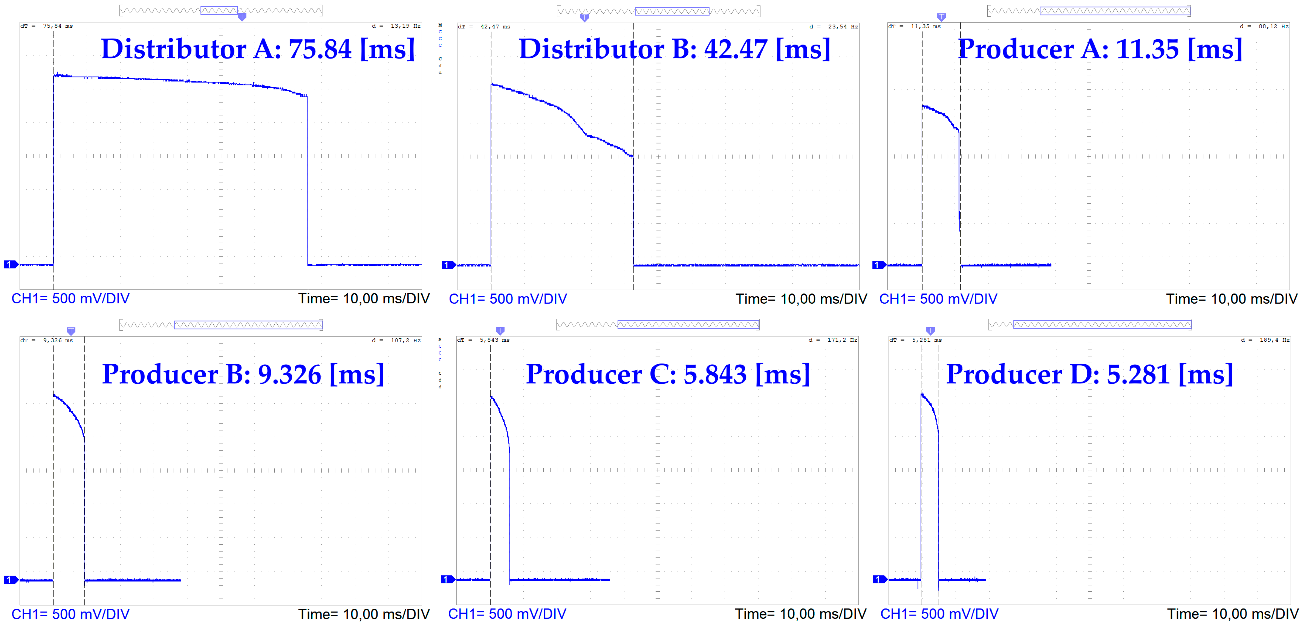
Examples of individual results (randomly selected among measurement series consisting of thirty destructive tests) are shown in Figure 8.
When analyzing the obtained results, it should be concluded that, due to the particular significance and nature of fire alarm systems, it is most desired to employ various solutions combining element redundancy while ensuring that the additional electronic subassembly or a system made up of such elements satisfies the assumptions of an anti-failure subsystem (shielding, intervention or emergency), hence, one that actively increases system reliability [1,4,100,101].
It should be noted that technological advancement entails a need to review previously applied classification criteria for individual electronic subassemblies and consider the introduction of additional, more detailed ones [2,102]. Based on sample results, it can be concluded that fuse-links characterized by the same, currently applied, most important technical parameters can trip a circuit at noticeably different time intervals [3,5,80]. This proves the need to introduce additional parameters classifying these subassemblies. It is worthwhile to discuss a proposed introduction of a unified parameter of protective potential that would be associated with the impact of the employed fuse-link from a given manufacturer on the reliability of an electronic security system wherein such an element would operate [2,103,104].
It should be emphasized that the observed discrepancies in the Tcb circuit breaking time (often significant) of individual products have not been the subject of other scientific research so far. The problem is described in more detail in [54]. The authors would like to emphasize that due to the significant responsibility of the ESS (property, but in extreme cases also the health and life of people), there is an urgent need to conduct further research to verify whether extending the process of circuit break through fuse links affects the reliability of the systems in question. Which, in consequence, will also have a direct and degenerating impact on the level of security provided by ESS.

5. Conclusions

Operation-related issues, particularly the reliability of power supply for electronic security systems (ESS) located in buildings, facilities and over vast areas of state critical infrastructure, are extremely important, not only because of ensuring an appropriate security level. All ESSs are designed, installed and later operated and maintained (serviced) in line with applicable regulations and standards, as well as legal acts assigned to FAS monitoring fire threats—including life, health and property accumulated within a protected area. Power supply, particularly the reliability and quality of rated industrial power grid voltage parameters, impacts the fitness and proper operation of elements, devices and modules that constitute components of individual security systems.
These systems may function as stand-alone (e.g., FAS) or integrated into a single, large technical object, mutually complementary for the purposes of developing an appropriate security level—e.g., access control system (ACS)—area entrance using magnetic cards, supplemented by closed-circuit television (CCTV)—face recognition targeting people entering/exiting the monitored area.
The authors of the paper developed two different models (graphs) if the operation process for different security system employment configurations. The first of the proposed models utilizes two different intrusion detection systems (IDS) located in buildings No. 1 and 2. IDSs employ two types of power supply devices. Building No. 1—is an A-type power supply device, while building No. 2 contains a C-type source due to the large distances between these technical facilities. To ensure reliability and the implementation of the diagnosing process, additional diagnostic modules were employed in power supply systems. They are only responsible for implementing diagnostic testing and inference processes related to the power supply. In the event of using an IDS with a C-type power supply, the authors employed an additional diagnostic module shown in Figure 3.
The λ failure and μ recovery (repair) rates for individual security system operation process models were determined by the authors by studying 20 different power supply systems. Most of the tested power supply systems, operated in reality in buildings, can be illustrated via two operation process graphs—Figure 3 and Figure 4, respectively. The conducted functional computer simulation of two power supply types for the same operation time t = 200 [h] provided the following probabilities of a system staying in a state of full fitness R01(t) = 0.999995 (system with C-type power supply) and R02(t) = 0.9999943 (operation of three different security systems, including two responsible for human life and health—e.g., FAS). The values of the system’s probability of staying in a state of full fitness are practically equal to one, which means that power supply systems are fully fit within this time interval. As can be seen based on the presented graphs illustrating the probability of the systems staying in the state of full fitness—Figure 4 and Figure 6, there is a slight decline in the value of both R01(t) and R01(t)—within the operation time of t = 20 [h] (Figure 4) and t = 10 [h] (Figure 6), respectively.
This is followed by the stabilization of the R01(t) and R02(t) function values at a constant level shown accordingly in the discussed Figs., e.g., Figure 6 is R02(t) = 0.9999943. This short operation time of security systems [0–10 or 20 h], wherein the full fitness probability changes results from the occurrence of the so-called infant age, where all electronic elements, devices and modules operate for the first time and implement their functions under rated load. This is the so-called fine-tuning process, which most usually involves partial or total—critical damage. However, in the case of the discussed solutions in the field of operational ESS power supply systems—these objects exhibit significant values of the probability of staying in a state of full fitness—it is determined by the application of hot reserve in the form of a battery bank, regardless of the ESS type.
The authors of the article tested miniature fuse-links constituting the so-called redundant element in power supply devices and are responsible for interrupting a catastrophic failure process in the case of—e.g., a short-circuit in input/output circuits or the presence of overvoltage pulses in an industrial power grid. To this end, the authors developed an electronic device—Figure 7, which enables rather accurate implementation of the fuse testing process with preset input current forced action. The oscillograms in Figure 8 show a response current pulse generated within the output circuit of the tested fuse at varying current forced action applied to the studied element.
Individual tcb circuit breaking times for selected marketed fuse-links with the same primary technical parameters, under direct overcurrent with an average value of 5.70 [A], are different, from a max. of 75.84 to a min. of 5.281 [ms]. This is the so-called manufacturing spread of components employed in power supplies, and it is significant over time.

Author Contributions

Conceptualization, J.P., J.M.Ł. and A.R.; methodology, J.P. and A.R.; validation, J.M.Ł., J.P. and A.R.; formal analysis, A.R., J.P. and J.M.Ł.; investigation, J.P. and A.R.; resources, J.M.Ł. and J.P.; data curation, A.R. and J.P.; writing—original draft preparation, J.M.Ł., J.P. and A.R.; writing—review and editing, J.P. and A.R.; visualization, J.P. and A.R.; supervision J.P., J.M.Ł. and A.R.; project administration, J.P. and J.M.Ł.; funding acquisition, J.M.Ł., J.P. and A.R. All authors have read and agreed to the published version of the manuscript.

Funding

This work was financed/co-financed by Military University of Technology under research project UGB 751.

Data Availability Statement

The data presented in this study are available on request from the corresponding author due to legal reasons.

Conflicts of Interest

The authors declare no conflicts of interest.

Abbreviations

ACUAlarm Control Unit
FASFire Alarm System
ARCAlarm Receiving Centre
SWS Sound Warning System
FACUFire Alarm Control Unit
FFEDFixed Fire Extinguishing Devices
ESSElectronic Security System
AWSAudio Warning System
MCPManual Call Point
AFSTDAlarm and Failure Signal Transmitting Device
SCIState Critical Infrastructure
TF1–TF9test fire designations
kg(t)availability coefficient
µrecovery rate coefficient
λfailure rate coefficient,
RO(t)probability function of a FAS staying in the SPZ state (full fitness)
QZB(t)probability function of a FAS staying in the SZB state (safety hazard)
QB(t)probability function of a FAS staying in the SPZ state (safety unreliability)
λZB1failure rate, transition of a selected FAS from the SPZ state to the SZB state
μPZ1recovery rate, transition from the SZB state to the SPZ state
PD1detection loop No. 1
λCSPintensity of transition from the SPZ state of full fitness to the SB state of safety unreliability
kg(t)availability coefficient

References

  1. Klimczak, T.; Paś, J. Basics of Exploitation of Fire Alarm Systems in Transport Facilities; Military University of Technology: Warsaw, Poland, 2020. [Google Scholar]
  2. Mondal, M.S.; Prasad, V.; Kumar, R.; Saha, N.; Guha, S.; Ghosh, R.; Mukhopadhyay, A.; Sarkar, S. Automating Fire Detection and Suppression with Computer Vision: A Multi-Layered Filtering Approach to Enhanced Fire Safety and Rapid Response. Fire Technol. 2023, 59, 1555–1583. [Google Scholar] [CrossRef]
  3. Krzykowski, M.; Paś, J.; Rosiński, A. Assessment of the level of reliability of power supplies of the objects of critical infrastructure. IOP Conf. Ser. Earth Environ. Sci. 2019, 214, 012018. [Google Scholar] [CrossRef]
  4. Jakubowski, K.; Paś, J.; Duer, S.; Bugaj, J. Operational Analysis of Fire Alarm Systems with a Focused, Dispersed and Mixed Structure in Critical Infrastructure Buildings. Energies 2021, 14, 7893. [Google Scholar] [CrossRef]
  5. Hulida, E.; Pasnak, I.; Koval, O.; Tryhuba, A. Determination of the Critical Time of Fire in the Building and Ensure Successful Evacuation of People. Period. Polytech. Civ. Eng. 2019, 63, 308–316. [Google Scholar] [CrossRef]
  6. Festag, S. False alarm ratio of fire detection and fire alarm systems in Germany—A meta-analysis. Fire Saf. J. 2016, 79, 119–126. [Google Scholar] [CrossRef]
  7. Stawowy, M.; Rosiński, A.; Siergiejczyk, M.; Perlicki, K. Quality and Reliability-Exploitation Modeling of Power Supply Systems. Energies 2021, 14, 2727. [Google Scholar] [CrossRef]
  8. Smolenski, R.; Lezynski, P.; Bojarski, J.; Drozdz, W.; Long, L.C. Electromagnetic compatibility assessment in multiconverter power systems—Conducted interference issues. Measurement 2020, 165, 108119. [Google Scholar] [CrossRef]
  9. Duer, S.; Rokosz, K.; Zajkowski, K.; Bernatowicz, D.; Ostrowski, A.; Woźniak, M.; Iqbal, A. Intelligent Systems Supporting the Use of Energy Devices and Other Complex Technical Objects: Modeling, Testing, and Analysis of Their Reliability in the Operating Process. Energies 2022, 15, 6414. [Google Scholar] [CrossRef]
  10. Li, F.; Chen, S.; Wang, X.; Feng, F. Pedestrian evacuation modeling and simulation on metro platforms considering panic impacts. Procedia Soc. Behav. Sci. 2014, 138, 314–322. [Google Scholar] [CrossRef]
  11. Klimczak, T.; Paś, J.; Duer, S.; Rosiński, A.; Wetoszka, P.; Białek, K.; Mazur, M. Selected Issues Associated with the Operational and Power Supply Reliability of Fire Alarm Systems. Energies 2022, 15, 8409. [Google Scholar] [CrossRef]
  12. Dziula, P.; Kołowrocki, K.; Soszyńska-Budny, J. Maritime Transportation System Safety-Modeling and Identification. TransNav. Int. J. Mar. Navig. Saf. Transp. 2013, 7, 169–175. [Google Scholar] [CrossRef]
  13. Suproniuk, M.; Skibko, Z.; Stachno, A. Diagnostics of some parameters of electricity generated in wind farms. Przegląd Elektrotechniczny 2019, 95, 105–108. [Google Scholar]
  14. Lewczuk, K.; Kłodawski, M.; Gepner, P. Energy Consumption in a Distributional Warehouse: A Practical Case Study for Different Warehouse Technologies. Energies 2021, 14, 2709. [Google Scholar] [CrossRef]
  15. Duer, S. Assessment of the Operation Process of Wind Power Plant’s Equipment with the Use of an Artificial Neural Network. Energies 2020, 13, 2437. [Google Scholar] [CrossRef]
  16. Wisnios, M.; Pas, J. The assessment of exploitation process of power for access control system. Int. Conf. Energy Environ. Mater. Syst. 2017, 19, 01034. [Google Scholar] [CrossRef]
  17. Festag, S. False Alarm Study, 2nd ed.; Erich Schmidt Verlag: Berlin, Germany, 2022. [Google Scholar]
  18. Sousa, E.; Tomé, R.; Ribeiro, P.; Dutra, I.; Rodrigues, A. An Online Anomaly Detection Approach for Fault Detection on Fire Alarm Systems. Sensors 2023, 23, 4902. [Google Scholar] [CrossRef] [PubMed]
  19. Zhang, W.; Xu, D.; Enjeti, P.N.; Li, H.; Hawke, J.T.; Krishnamoorthy, H.S. Survey on fault-tolerant techniques for power electronic converters. IEEE Trans. Power Electron. 2014, 29, 6319–6331. [Google Scholar] [CrossRef]
  20. Zieja, M.; Szelmanowski, A.; Pazur, A.; Kowalczyk, G. Computer Life-Cycle Management System for Avionics Software as a Tool for Supporting the Sustainable Development of Air Transport. Sustainability 2021, 13, 1547. [Google Scholar] [CrossRef]
  21. Chao, C.; Zheng, X.; Weng, Y.; Liu, Y.; Gao, P.; Nengling, T. Adaptive distance protection based on the analytical model of additional impedance for inverter-interfaced renewable power plants during asymmetrical faults. IEEE Trans. Power Deliv. 2022, 37, 3823–3834. [Google Scholar] [CrossRef]
  22. Shamsi, P.; Fahimi, B. Dynamic Behavior of Multiport Power Electronic Interface under Source/Load Disturbances. IEEE Trans. Ind. Electron. 2013, 60, 4500–4511. [Google Scholar] [CrossRef]
  23. Jiang, W.; Fahimi, B. Multiport Power Electronic Interface—Concept, Modelling, and Design. IEEE Trans. Power Electron. 2011, 26, 1890–1900. [Google Scholar] [CrossRef]
  24. Zajkowski, K. Two-stage reactive compensation in a three-phase four-wire systems at nonsinusoidal periodic waveforms. Electr. Power Syst. Res. 2020, 184, 106296. [Google Scholar] [CrossRef]
  25. Ying, X.; Zhang, X.P.; Yang, C. Commutation failure elimination of LCC HVDC systems using thyristor-based controllable capacitors. IEEE Trans. Power Deliv. 2017, 33, 1448–1458. [Google Scholar]
  26. Nitta, N.; Wu, F.; Lee, J.T.; Yushin, G. Li-ion battery materials: Present and future. Mater. Today 2015, 18, 252–264. [Google Scholar] [CrossRef]
  27. Schmuch, R.; Wagner, R.; Hörpel, G.; Placke, T.; Winter, M. Performance and cost of materials for lithium-based rechargeable automotive batteries. Nat. Energy 2018, 3, 267–278. [Google Scholar] [CrossRef]
  28. Cavers, H.; Molaiyan, P.; Abdollahifar, M.; Lassi, U.; Kwade, A. Perspectives on Improving the Safety and Sustainability of High Voltage Lithium-Ion Batteries Through the Electrolyte and Separator Region. Adv. Energy Mater. 2022, 12, 2200147. [Google Scholar] [CrossRef]
  29. Młynarski, S.; Pilch, R.; Smolnik, M.; Szybka, J.; Wiązania, G. A model of an adaptive strategy of preventive maintenance of complex technical objects. Eksploat. Niezawodn. Maint. Reliab. 2020, 22, 35–41. [Google Scholar] [CrossRef]
  30. Zhou, Q.; Xu, Y.; Qi, X.; Zhang, Z. Design and Simulation of a Highly Reliable Modular High-Power Current Source. Energies 2022, 15, 8593. [Google Scholar] [CrossRef]
  31. Chen, G.; Chen, L.; Deng, Y.; Wang, K.; Qing, X. Topology-reconfigurable fault-tolerant LLC converter with high reliability and low cost for more electric aircraft. IEEE Trans. Power Electron. 2018, 34, 2479–2493. [Google Scholar] [CrossRef]
  32. International Standard IEC 60050-482:2004; International Electrotechnical Vocabulary (IEV)—Part 482: Primary and Secondary Cells and Batteries. International Electrotechnical Commission: Geneva, Switzerland, 7 April 2004; ISBN 283187274X.
  33. Duer, S. Expert knowledge base to support the maintenance of a radar system. Def. Sci. J. 2010, 60, 531–540. [Google Scholar] [CrossRef]
  34. He, Y.; Zhang, X.; Wang, R.; Cheng, M.; Gao, Z.; Zhang, Z.; Yu, W. Faulty section location method based on dynamic time warping distance in a resonant grounding system. Energies 2022, 15, 4923. [Google Scholar] [CrossRef]
  35. Vasile, D.-C.; Svasta, P.; Pantazica, M. Preventing the Temperature Side Channel Attacks on Security Circuits. In Proceedings of the 2019 IEEE 25th International Symposium for Design and Technology in Electronic Packaging (SIITME), Cluj-Napoca, Romania, 23–26 October 2019; IEEE: Piscataway Township, NJ, USA, 2019; pp. 244–247. [Google Scholar]
  36. Weese, M.; Martinez, W.; Megahed, F.M.; Jones-Farmer, L.A. Statistical Learning Methods Applied to Process Monitoring: An Overview and Perspective. J. Qual. Technol. 2016, 48, 4–24. [Google Scholar] [CrossRef]
  37. Ragab, A.; El-Koujok, M.; Poulin, B.; Amazouz, M.; Yacout, S. Fault diagnosis in industrial chemical processes using inter-pretable patterns based on Logical Analysis of Data. Expert Syst. Appl. 2018, 95, 368–383. [Google Scholar] [CrossRef]
  38. Oszczypała, M.; Ziółkowski, J.; Małachowski, J. Analysis of Light Utility Vehicle Readiness in Military Transportation Systems Using Markov and Semi-Markov Processes. Energies 2022, 15, 5062. [Google Scholar] [CrossRef]
  39. Buye, R. Critical Examination of the PESTEL Analysis Model; Project: Action Research for Development; Research Gate: Berlin, Germany, 2021. [Google Scholar]
  40. Chen, Y.-J.; Lai, Y.-S.; Lin, Y.-H. BIM-based augmented reality inspection and maintenance of fire safety equipment. Autom. Constr. 2020, 110, 103041. [Google Scholar] [CrossRef]
  41. Abdelghany, M.; Ahmad, W.; Tahar, S.T. Event Tree Reliability Analysis of Electrical Power Generation Network using Formal Techniques. In Proceedings of the 2020 IEEE Electric Power and Energy Conference (EPEC), Edmonton, Canada, 9–10 November 2020. [Google Scholar]
  42. Badrzadeh, B.; Gupta, M.; Singh, N.; Petersson, A.; Max, L.; Høgdahl, M. Power system harmonic analysis in wind power plants-Part I: Study methodology and techniques. In Proceedings of the IEEE Industry Applications Society Annual Meeting, Las Vegas, NV, USA, 7–11 October 2012; pp. 1–11. [Google Scholar]
  43. Kwasiborska, A.; Skorupski, J. Assessment of the Method of Merging Landing Aircraft Streams in the Context of Fuel Consumption in the Airspace. Sustainability 2021, 13, 12859. [Google Scholar] [CrossRef]
  44. Celiński, I.; Burdzik, R.; Młyńczak, J.; Kłaczyński, M. Research on the Applicability of Vibration Signals for Real-Time Train and Track Condition Monitoring. Sensors 2022, 22, 2368. [Google Scholar] [CrossRef]
  45. Kozyra, J.; Łukasik, Z.; Kuśmińska-Fijałkowska, A.; Kaszuba, P. The impact of selected variants of remote control on power supply reliability indexes of distribution networks. Electr. Eng. 2021, 104, 1255–1264. [Google Scholar] [CrossRef]
  46. Xu, X.; Hu, W.; Liu, W.; Du, Y.; Huang, R.; Huang, Q.; Chen, Z. Risk management strategy for a renewable power supply system in commercial buildings considering thermal comfort and stochastic electric vehicle behaviors. Energy Convers. Manag. 2021, 230, 113831. [Google Scholar] [CrossRef]
  47. Kołowrocki, K.; Soszyńska-Budny, J. Reliability and Safety of Complex Technical Systems and Processes; Springer: London, UK, 2011. [Google Scholar]
  48. Duer, S.; Scaticailov, S.; Paś, J.; Duer, R.; Bernatowicz, D. Taking decisions in the diagnostic intelligent systems on the basis information from an artificial neural network. MATEC Web Conf. 2018, 178, 07003. [Google Scholar] [CrossRef]
  49. Slowak, P.; Kaniewski, P. Stratified Particle Filter Monocular SLAM. Remote Sens. 2021, 13, 3233. [Google Scholar] [CrossRef]
  50. Nor, N.M.; Hassan, C.R.C.; Hussain, M.A. A review of data-driven fault detection and diagnosis methods: Applications in chemical process systems. Rev. Chem. Eng. 2019, 36, 513–553. [Google Scholar] [CrossRef]
  51. Variny, M.; Jediná, D.; Kizek, J.; Illés, P.; Lukáč, L.; Janošovský, J.; Lesný, M. An Investigation of the Techno-Economic and Environmental Aspects of Process Heat Source Change in a Refinery. Processes 2019, 7, 776. [Google Scholar] [CrossRef]
  52. Kim, H.; Lee, M.; Jung, W.-S.; Oh, S.-H. Temperature Monitoring Techniques of Power Cable Joints in Underground Utility Tunnels Using a Fiber Bragg Grating. ICT Express 2022, 1252, 626–632. [Google Scholar] [CrossRef]
  53. Aminossadati, S.M.; Mohammed, N.M.; Shemshad, J. Distributed Temperature Measurements Using Optical Fibre Technology in an Underground Mine Environment. Tunn. Undergr. Space Technol. 2010, 25, 220–229. [Google Scholar] [CrossRef]
  54. Paś, J.; Rosiński, A.; Wetoszka, P.; Białek, K.; Klimczak, T.; Siergiejczyk, M. Assessment of the Impact of Emitted Radiated Interference Generated by a Selected Rail Traction Unit on the Operating Process of Trackside Video Monitoring Systems. Electronics 2022, 11, 2554. [Google Scholar] [CrossRef]
  55. Madan, M.; Gupta, M.; Liang, J.; Homma, N. Static and Dynamic Neural Networks, From Fundamentals to Advanced Theory; John Wiley & Sons, Inc.: Hoboken, NJ, USA, 2003. [Google Scholar] [CrossRef]
  56. Soszyńska-Budny, J. General approach to critical infrastructure safety modelling. In Safety Analysis of Critical Infrastructure; Lecture Notes in Intelligent Transportation and Infrastructure; Springer: Cham, Switzerland, 2021. [Google Scholar]
  57. Zajkowski, K. The method of solution of equations with coefficients that contain measurement errors, using artificial neural network. Neural Comput. Appl. 2014, 24, 431–439. [Google Scholar] [CrossRef]
  58. Duer, S.; Zajkowski, K.; Harničárová, M.; Charun, H.; Bernatowicz, D. Examination of Multivalent Diagnoses Developed by a Diagnostic Program with an Artificial Neural Network for Devices in the Electric Hybrid Power Supply System “House on Water”. Energies 2021, 14, 2153. [Google Scholar] [CrossRef]
  59. Duer, S.; Valicek, J.; Paś, J.; Stawowy, M.; Bernatowicz, D.; Duer, R.; Walczak, M. Neural Networks in the Diagnostics Process of Low-Power Solar Plant Devices. Energies 2021, 14, 2719. [Google Scholar] [CrossRef]
  60. Talaat, F.M.; ZainEldin, H. An improved fire detection approach based on YOLO-v8 for smart cities. Neural Comput. Appl. 2023, 35, 20939–20954. [Google Scholar] [CrossRef]
  61. Sobral, J.; Ferreira, L. Maintenance of fire sprinkler systems based on the dynamic assessment of its condition. Process Saf. Prog. 2016, 35, 84–91. [Google Scholar] [CrossRef]
  62. Kumar Saxena, M.; Sharma, R.K.; Kumar, S.; Kishore, J.; Nathwani, R.K.; Gupta, A.M.; Kumar, A.; Kumar, A.; Bhatnagar, V.K.; Prakash, O.; et al. Studies on Thermal Profile Measurement and Fire Detection in a Power Supply Cable of a Synchrotron Radiation Source by Raman Optical Fiber Distributed Temperature Sensor System. Opt. Fiber Technol. 2022, 73, 103020. [Google Scholar] [CrossRef]
  63. Mutlu, N.G.; Altuntas, S. Risk analysis for occupational safety and health in the textile industry: Integration of FMEA, FTA, and BIFPET methods. Int. J. Ind. Ergon. 2019, 72, 222–240. [Google Scholar] [CrossRef]
  64. Łukasiak, J.; Wiśnios, M.; Rosiński, A. Method for Evaluating the Effectiveness of Electrical Circuit Protection with Miniature Fuse-Links. Energies 2023, 16, 960. [Google Scholar] [CrossRef]
  65. Gupta, S.; Kanwar, S.; Kashyap, M. Performance characteristics and assessment of fire alarm system. Mater. Today Proc. 2022, 57, 2036–2040. [Google Scholar] [CrossRef]
  66. Valouch, J. Integrated alarm systems. In Computer Applications for Software Engineering, Disaster Recovery, and Business Continuity; Series: Communications in Computer and Information Science XVIII; Springer: Berlin/Heidelberg, Germany, 2012; Volume 340, pp. 369–379. ISSN 1865-0929. [Google Scholar]
  67. Zhang, W.; Zhang, X.; Luo, X.; Zhao, T. Reliability model and critical factors identification of construction safety management based on system thinking. J. Civ. Eng. Manag. 2019, 25, 362–379. [Google Scholar] [CrossRef]
  68. e Almeida, R.V.; Crivellaro, F.; Narciso, M.; Sousa, A.I.; Vieira, P. Bee2Fire: A deep learning powered forest fire detection system. In Proceedings of the ICAART 2020—12th International Conference on Agents and Artificial Intelligence, Valletta, Malta, 22–24 February 2020; SciTePress: Setúbal, Portugal, 2020; Volume 2, pp. 603–609. [Google Scholar]
  69. Shaw, E.; Roper, T.; Nilsson, T.; Lawson, G.; Cobb, S.V.; Miller, D. The heat is on: Exploring user behaviour in a multisensory virtual environment for fire evacuation. In Proceedings of the 2019 CHI Conference on Human Factors in Computing Systems, Glasgow, UK, 4–9 May 2019; pp. 1–13. [Google Scholar]
  70. Keding, L. An optimization of intelligent fire alarm system for high-rise building based on ANASYS. In Intelligence Computation and Evolutionary Computation; Du, Z., Ed.; Springer: Berlin/Heidelberg, Germany, 2013; pp. 415–421. [Google Scholar]
  71. Huang, X.; Du, L. Fire Detection and Recognition Optimization Based on Virtual Reality Video Image. IEEE Access 2020, 8, 77951–77961. [Google Scholar] [CrossRef]
  72. Li, Y.; Guldenmund, F.W. Safety management systems: A broad overview of the literature. Saf. Sci. 2018, 103, 94–123. [Google Scholar] [CrossRef]
  73. Zhao, H.; Schwabe, A.; Schläfli, F.; Thrash, T.; Aguilar, L.; Dubey, R.K.; Karjalainen, J.; Hölscher, C.; Helbing, D.; Schinazi, V.R. Fire evacuation supported by centralized and decentralized visual guidance systems. Saf. Sci. 2022, 145, 105451. [Google Scholar] [CrossRef]
  74. Frangopol, D.M.; Liu, M. Maintenance and management of civil infrastructure based on condition, safety, optimization, and lifecycle cost. Struct. Infrastruct. Eng. 2007, 3, 29–41. [Google Scholar] [CrossRef]
  75. Andrzejczak, K.; Bukowski, L. A method for estimating the probability distribution of the lifetime for new technical equipment based on expert judgement. Eksploat. Niezawodn. Maint. Reliab. 2021, 23, 757–769. [Google Scholar] [CrossRef]
  76. Luo, Y.; Chen, R.; Zhu, Y.; Cheng, J.; Wei, M. The Analysis of Magnetic Field Intensity and Induced Current under Live Working Based on the Finite Element Method. In Proceedings of the 2015 Fifth International Conference on Instrumentation and Measurement, Computer, Communication and Control (IMCCC), Qinhuangdao, China, 18–20 September 2015; pp. 192–195. [Google Scholar]
  77. Soliman, H.; Sudan, K.; Mishra, A. A smart forest-fire early detection sensory system: Another approach of utilizing wireless sensor and neural networks. In Proceedings of the 2010 IEEE Sensors, Waikoloa, HI, USA, 1–4 November 2010; Institute of Electrical and Electronics Engineers (IEEE): New York, NY, USA, 2010; pp. 1900–1904. [Google Scholar]
  78. Buemi, A.; Giacalone, D.; Naccari, F.; Spampinato, G. Efficient fire detection using fuzzy logic. In Proceedings of the 2016 IEEE 6th International Conference on Consumer Electronics Berlin (ICCE-Berlin), Berlin, Germany, 5–7 September 2016; Volume 2016, pp. 237–240. [Google Scholar] [CrossRef]
  79. Dziula, P.; Paś, J. Low Frequency Electromagnetic Interferences Impact on Transport Security Systems Used in Wide Transport Areas. TransNav Int. J. Mar. Navig. Saf. Sea Transp. 2018, 12, 251–258. [Google Scholar] [CrossRef]
  80. Siergiejczyk, M.; Paś, J.; Rosiński, A. Evaluation of Safety of Highway CCTV System’s Maintenance Process. In Telematics—Support for Transport. TST 2014. Communications in Computer and Information Science; Mikulski, J., Ed.; Springer: Berlin/Heidelberg, Germany, 2014; Volume 471. [Google Scholar] [CrossRef]
  81. Fridolf, K.; Nilsson, D.; Frantzich, H. Fire Evacuation in Underground Transportation Systems: A Review of Accidents and Empirical Research. Fire Technol. 2013, 49, 451–475. [Google Scholar] [CrossRef]
  82. Chung, I.-H.; Lin, Y.-H. Exploring the Impact of Parallel Architecture on Improving Adaptable Neuro-Fuzzy Inference Systems for Gas-Insulated Switch Defect Recognition. Energies 2022, 15, 3940. [Google Scholar] [CrossRef]
  83. Chrzan, M.; Kornaszewski, M.; Ciszewski, T. Renovation of marine telematics objects in the process of exploitation. In Management Perspective for Transport Telematics; Springer: Cham, Switzerland, 2018; pp. 337–351. [Google Scholar]
  84. Żyluk, A.; Kuźma, K.; Grzesik, N.; Zieja, M.; Tomaszewska, J. Fuzzy Logic in Aircraft Onboard Systems Reliability Evaluation—A New Approach. Sensors 2021, 21, 7913. [Google Scholar] [CrossRef] [PubMed]
  85. Świderski, A.; Jóźwiak, A.; Jachimowski, R. Operational quality measures of vehicles applied for the transport services evaluation using artificial neural networks. Eksploat. Niezawodn. Maint. Reliab. 2018, 20, 292–299. [Google Scholar] [CrossRef]
  86. Zajkowski, K.; Rusica, I.; Palkova, Z. The use of CPC theory for energy description of two nonlinear receivers. MATEC Web Conf. 2018, 178, 09008. [Google Scholar] [CrossRef]
  87. Polak, R.; Laskowski, D.; Matyszkiel, R.; Łubkowski, P.; Konieczny, Ł.; Burdzik, R. Optimizing the data flow in a network communication between railway nodes. In Research Methods and Solutions to Current Transport Problems, Proceedings of the International Scientific Conference Transport of the 21st Century, Ryn, Poland, 9–12 June 2019; Advances in Intelligent Systems and Computing; Siergiejczyk, M., Krzykowska, K., Eds.; Springer: Cham, Switzerland, 2020; Volume 1032, pp. 351–362. [Google Scholar] [CrossRef]
  88. Østrem, L.; Sommer, M. Inherent fire safety engineering in complex road tunnels—Learning between industries in safety management. Saf. Sci. 2021, 134, 105062. [Google Scholar] [CrossRef]
  89. Rosiński, A.; Paś, J.; Białek, K.; Wetoszka, P. Method for Assessing Reliability of the Power Supply System for Electronic Security Systems of Intelligent Buildings Taking into Account External Natural Interference. Eksploat. Niezawodn. Maint. Reliab. 2024, 26, 176375. [Google Scholar] [CrossRef]
  90. Willquista, P.; Törner, M. Identifying and analysing hazards in manufacturing industry—A review of selected methods and development of a framework for method applicability. Int. J. Ind. Ergon. 2003, 32, 165–180. [Google Scholar] [CrossRef]
  91. Wang, H.; Pham, H. Some maintenance models and availability with imperfect maintenance in production systems. Ann. Oper. Res. 1999, 91, 305–318. [Google Scholar] [CrossRef]
  92. Clavijo, N.; Melo, A.; Câmara, M.M.; Feital, T.; Anzai, T.K.; Diehl, F.C.; Thompson, P.H.; Pinto, J.C. Development and Application of a Data-Driven System for Sensor Fault Diagnosis in an Oil Processing Plant. Processes 2019, 7, 436. [Google Scholar] [CrossRef]
  93. Azmil, M.S.A.; Ya’Acob, N.; Tahar, K.N.; Sarnin, S.S. Wireless fire detection monitoring system for fire and rescue application. In Proceedings of the 2015 IEEE 11th International Colloquium on Signal Processing & Its Applications (CSPA), Kuala Lumpur, Malaysia, 6–8 March 2015; Volume 10, pp. 84–89. [Google Scholar]
  94. Popov, I. Quality Management Essentials; World Scientific: Hackensack, NJ, USA, 2022. [Google Scholar]
  95. Będkowski, L.; Dąbrowski, T. Podstawy Eksploatacji: Część 2: Podstawy Niezawodności Eksploatacyjnej; Wojskowa Akademia Techniczna: Warszawa, Poland, 2006; ISBN 978-83-89399-31-1. [Google Scholar]
  96. PN-EN 50131-1:2009; Systemy Alarmowe—Systemy Sygnalizacji Włamania i Napadu. The Polish Committee for Standardization (Polski Komitet Normalizacyjny—PKN): Warsaw, Poland, 2009.
  97. SIBA Polska, sp. z o.o. Poradnik: Bezpieczniki Topikowe: Poradnik dla Użytkowników Bezpieczników Topikowych Miniaturowych; SIBA Polska sp. z o.o.: Stare Babice, Poland, 2017. [Google Scholar]
  98. Veit, S.; Steiner, F. Systemic Approach for Risk-Based Third-Party Inspections of Fire Alarm Systems. In Proceedings of the 14th International Conference on Industrial Engineering and Operations Management, Dubai, United Arab Emirates, 12–14 February 2024. [Google Scholar] [CrossRef]
  99. van Coile, R.; Hopkin, D.; Lange, D.; Jomaas, G.; Bisby, L. The Need for Hierarchies of Acceptance Criteria for Probabilistic Risk Assessments in Fire Engineering. Fire Technol. 2019, 55, 1111–1146. [Google Scholar] [CrossRef]
  100. Jafari, M.J.; Pouyakian, M.; Khanteymoori, A.; Hanifi, S.M. Reliability evaluation of fire alarm systems using dynamic Bayesian networks and fuzzy fault tree analysis. J. Loss Prev. Process Ind. 2020, 67, 104229. [Google Scholar] [CrossRef]
  101. Jones, W.W. Implementing High Reliability Fire Detection in the Residential Setting. Fire Technol. 2012, 48, 233–254. [Google Scholar] [CrossRef]
  102. Kong, D.P.; Lu, S.X.; Ping, P. A Risk-Based Method of Deriving Design Fires for Evacuation Safety in Buildings. Fire Technol. 2017, 53, 771–791. [Google Scholar] [CrossRef]
  103. Veit, S.S.; Steiner, F. Proposed Changes to the Inspection Strategy for Fire Alarm Systems: Empirical Analysis of Weak Points and Technical Influencing Factors. Safety 2024, 10, 51. [Google Scholar] [CrossRef]
  104. Fu, Y. An analysis of the environmental impact of electromagnetic radiation in substations—Taking Qingnan Substation as an example. Environ. Sci. Manag. 2012, 37, 79–83. [Google Scholar]
Figure 1. Sample technical structures of AWS operated in buildings and vast areas, (a) focused, (b) distributed (designations and key in the Figure), (SWS)—Sound Warning System.
Energies 17 03665 g001
Figure 2. Ensuring power for ESS functioning in buildings and over a vast area (all designations and keys shown in Figure description).
Energies 17 03665 g002
Figure 3. Operation process graph for two intrusion detection systems located in buildings No. 1 and 2 and employing different power supply devices: building No. 1 (A-type power supply) and building No. 2 (C-type power supply). The designations in the graph are explained in the Figure. Owing to its reliability, building No. 2 employs an additional diagnostic module, acting as part of the so-called hot reserve, which monitors the BB powering IDS No. 2.
Energies 17 03665 g003
Figure 4. Waveform for the R0(t) probability function of a system in a state of full fitness.
Energies 17 03665 g004
Figure 6. Probability function R0(t) waveform for a system in a state of full fitness.
Energies 17 03665 g006
Figure 7. Schematic diagram of a miniature fuse-link tcb circuit breaking time measuring module.
Energies 17 03665 g007
Figure 8. Tcb circuit breaking time oscillograms for selected marketed fuse-links with the same primary technical parameters under direct overcurrent with an average value of 5.70 [A].
Energies 17 03665 g008
Disclaimer/Publisher’s Note: The statements, opinions and data contained in all publications are solely those of the individual author(s) and contributor(s) and not of MDPI and/or the editor(s). MDPI and/or the editor(s) disclaim responsibility for any injury to people or property resulting from any ideas, methods, instructions or products referred to in the content.